A Numerical Study on Influence of Temperature on Lubricant Film Characteristics of the Piston/Cylinder Interface in Axial Piston Pumps


1
School of Reliability and System Engineering, Beihang University, Beijing 100191, China
2
Sino-French Engineering School, Beihang University, Beijing 100191, China
3
Science and Technology on Reliability and Environmental Engineering Laboratory, Beihang University, Beijing 100191, China
*
Author to whom correspondence should be addressed.
Energies 2018, 11(7), 1842; https://doi.org/10.3390/en11071842
Submission received: 13 June 2018
/
Revised: 6 July 2018
/
Accepted: 12 July 2018
/
Published: 13 July 2018
(This article belongs to the Special Issue Fluid Flow and Heat Transfer)
Abstract
:The loss of kinetic energy of moving parts due to viscous friction of lubricant causes the reduction of piston pump efficiency. The viscosity of lubricant film is mainly affected by the thermal effect. In order to improve energy efficiency of piston pump, this research presents a numerical method to analyze the lubricant film characteristics in axial piston pumps, considering the thermal effect by the coupled multi-disciplinary model, which includes the fluid flow field expressed by Reynolds equation, temperature field expressed by energy equation and heat transfer equation, kinematics expressed by the motion equation. The velocity and temperature distributions of the gap flow of piston/cylinder interface in steady state are firstly numerically computed. Then the distributions are validated by the experiment. Finally, by changing the thermal boundary condition, the influence of thermal effect on the lubricant film, the eccentricity and the contact time between the piston and cylinder are analyzed. Results show that with the increase of temperature, the contact time increases in the form of a hyperbolic tangent function, which will reduce the efficiency of the axial piston pump. There is a critical temperature beyond which the contact time will increase rapidly, thus this temperature is the considered as a key point for the temperature design.
1. Introduction
As sliding pairs of axial piston pump move, both the metal parts and lubricants heat up, which causes temperature to increase significantly, decreases oil viscosity, reduces the bearing capacity of the oil, and intensifies the radial movement of the parts simultaneously [1]. The shape of the oil film changes, as does the lubrication mode, and the trajectory of piston could vary with the changing of oil film. The temperature impacts on oil film characteristics are important for analysis of the efficiency of the sliding pair.
Practical experience also indicates that the medium temperature significantly affects life. Cai et al. [2] tested the life of steel materials with a lubricating medium in the range of 23–175 °C and verified that the wear degree was directly related to the temperature. Specifically, the life of steel materials was closely related to the oil temperature distribution in the gap, and the distribution condition had a distinct influence on the oil characteristics. Unfortunately, the general test method could take temperature as the only variables; thus the results obtained by this way could only indicate the existence of a fuzzy relationship between temperature and life.
To indicate the relationship between the temperature and life more precisely, the behavior of lubricant film between the moving pair needs to be studied. Because the moving process is affected by fluid, solid, and thermal conditions together, it is a typical multiple-domain coupled problem. Many researchers have studied this problem around the bearing. McCallion et al. [3] solved the Reynolds and energy equations separately and neglected the effects of pressures during the calculation of temperature distribution. Ferron et al. [4] thoroughly studied the thermohydrodynamic (THD) performance of a plain journal bearing and determined its thermal characteristics. Rohde et al. [5] studied the elastic and thermal deformations in a slider bearing, noted that the variations in fluid viscosity with temperature were much more influential than solid deformation due to thermal and elastic effects. Researchers are still interested in the journal bearing where oil or gas is used as lubricants [6,7]. Lu et al. [8] conducted a thermal-fluid coupling study on characteristics of air–oil two phase flow and heat transfer in a micro unmanned aerial vehicle (UAV) bearing chamber. Some researchers took the cavitation into account [9] and others developed an efficient numerical method [10].
Axial piston pumps with constant pressure are the main type of engine-driven pumps (EDP), whose lifetime is affected by three sliding pairs, specifically the swash plate/slipper pair, cylinder/valve plate pair, and piston/cylinder pair, as shown in Figure 1.
Several Elasto Hydrodynamic Lubrication (EHL) researches have focused on the piston pump. Gels et al. developed a simulation tool based on the Reynolds equation, which allowed to vary the geometry of the sliding parts. With the help of this tool, Gels have found an optimal compromise of piston/cylinder interface which reduces the losses of energy [11]. Ma et al. presented a method on the basis of the EHL model to analyze the behavior of the swash plate/slipper pair [12]. Olems presented an analytical model that integrates the multiphysics characteristic equations including Reynolds Equation and energy equation [13]. Given inlet medium temperature and operating conditions, the temperature distribution in the clearance of piston/cylinder interface was determined using the model. A series of studies of MAHA research center were carried out based on Olem’s results. Ivantysynova et al. established a complete model of main sliding pairs for thermal analysis of oil film gap [14]. Kazama established a non-isothermal model of slipper/swash plate pair based on thermos-hydraulic dynamic theory [15]. Pelosi, Ivantysynova [16], and Zecchi [17] built an EHL model for the piston/cylinder pair and the swash plate/slipper pair. However, as shown in all these studies, few studies have modelled the interaction relationship among elastic, thermal and hydraulic behaviors only use numerical method without establishing the computer-aided design (CAD) model or using commercial software.
This study was designed to investigate the temperature distribution for the further accurate analysis on the thermal effect on the piston/cylinder interface. The flow velocity distribution in the piston/cylinder interface at a steady operating state of the piston pump (the output pressure of pump is steady) was calculated using the Reynolds equation. Then, the velocity distribution was imported into the model, considering the comprehensive effects of flow and temperature distributions in the gap, and the movement of moving components.
Only the numerical method is used during the whole simulation process. So, a parametric simulation model without the construction of a three-dimensional (3D) digital model was established, which is convenient for further application to the simulation of sliding pairs with different structures.
2. Description of Model
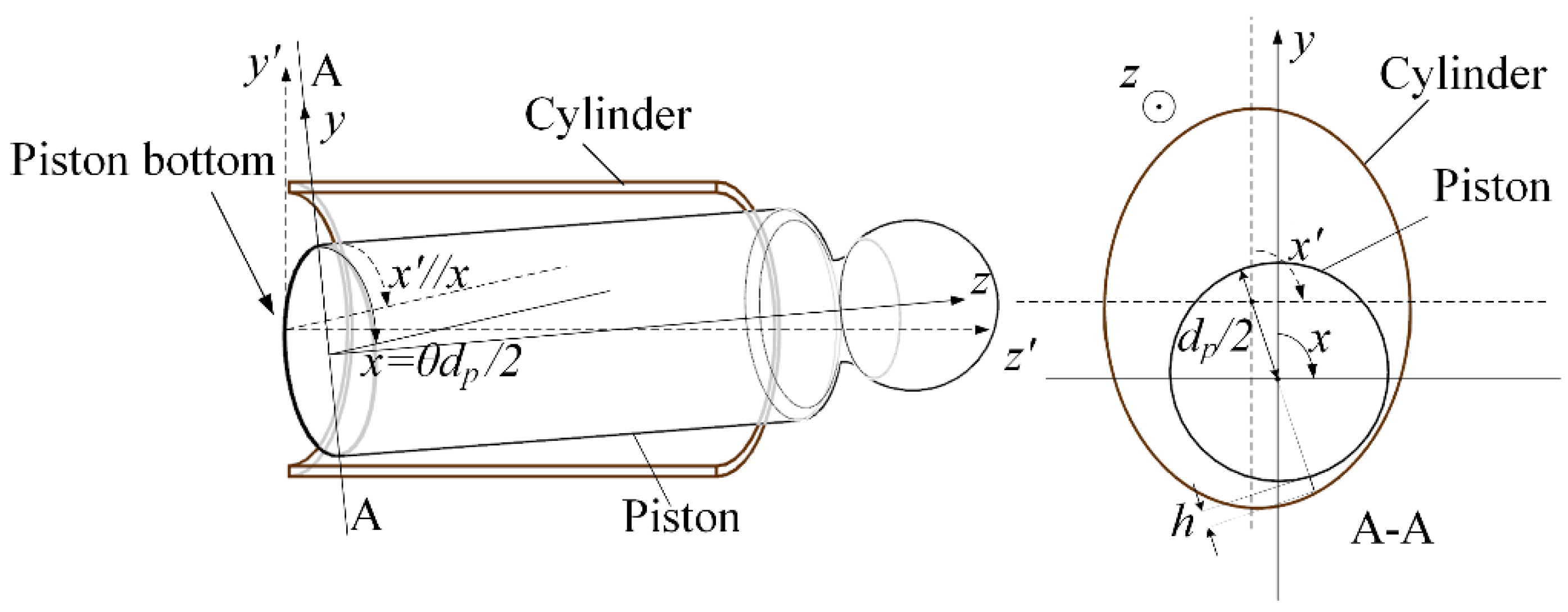
Under the assumption that the gap clearance (radial direction) was much smaller than the other two dimensions (circumferential and axial directions), an unwrapped Cartesian reference system was used for the description of the computation domain. The coordinates in this reference system are defined as Equation (1) and presented in Figure 2.
2.1. Mathematical Model
The axial piston pump has an odd number of pistons arranged in a circular array within a housing that is commonly referred to as a cylinder block. This cylinder block is driven to rotate about its axis of symmetry by an integral shaft that is aligned with the pumping pistons. A piston/cylinder interface is an assembly with one piston, one cylinder, and a film of lubricant oil. When the piston pump is operating, the piston moves in a linear reciprocating pattern within the cylinder block, suctioning or discharging oil.
Analysis of thermodynamic behavior of piston/cylinder interface in piston pumps is a fluid-structure interaction problem. The motion for fluid flow, heat transfer, and the motion of the piston are expected to be determined simultaneously. Because it is a time-dependent problem, one shaft revolution is divided into a number of discrete time steps. For each time step, the problem was considered time-independent.
The momentum transport for the fluid flow in the gap is described by the Reynolds equation [18]:
where h is the film thickness, μ is the oil viscosity, Uh is fluid velocity component along the circumferential direction on the boundary y = h, U0 is fluid velocity component along the circumferential direction on the boundary y = 0, Vh is fluid velocity component along the axial direction on the boundary y = h, V0 is fluid velocity component along the axial direction on boundary y = 0. y = h indicates the interface between the cylinder and oil, and y = 0 indicates the interface between the piston and oil. We assumed that the velocity of oil at oil/solid interface was the same as the solid. So Uh, U0, Vh, and V0 were constant.
The temperature field of the fluid is governed by the convection-conduction equation [18]:
where, To is oil temperature, co is the specific heat capacity at constant pressure of oil, ρo is the density of oil, ko is the thermal conductivity of oil, and φo is the viscous dissipation term.
The vector V in Equation (3) is the velocity of fluid composed by u and v which are determined by followed equations:
The temperature depends on the fluid velocity, so the last term in Equation (3) describes the energy dissipation:
Then the local viscosity of grid point in the gap can be calculated using the temperature distribution with the Reynolds viscosity temperature equation [18]:
where Tref is the reference temperature, μref is the viscosity of oil at reference temperature, and σ is the viscosity-temperature index.
The local viscosity is then used as new value in the following iteration cycle of algorithm.
For the temperature distribution inside the piston, the temperature distribution was determined using the heat conduction equation, which is written as Equation (7) [18]:
where Tp is the piston temperature, cp is the specific heat capacity at constant pressure of piston, ρp is the density of piston, kp is the thermal conductivity of piston, and φp is the viscous dissipation term.
Because the cylinder is geometrically much larger than the gap and the piston, the temperature is here considered a constant, Tc (case temperature).
2.2. Boundary Conditions
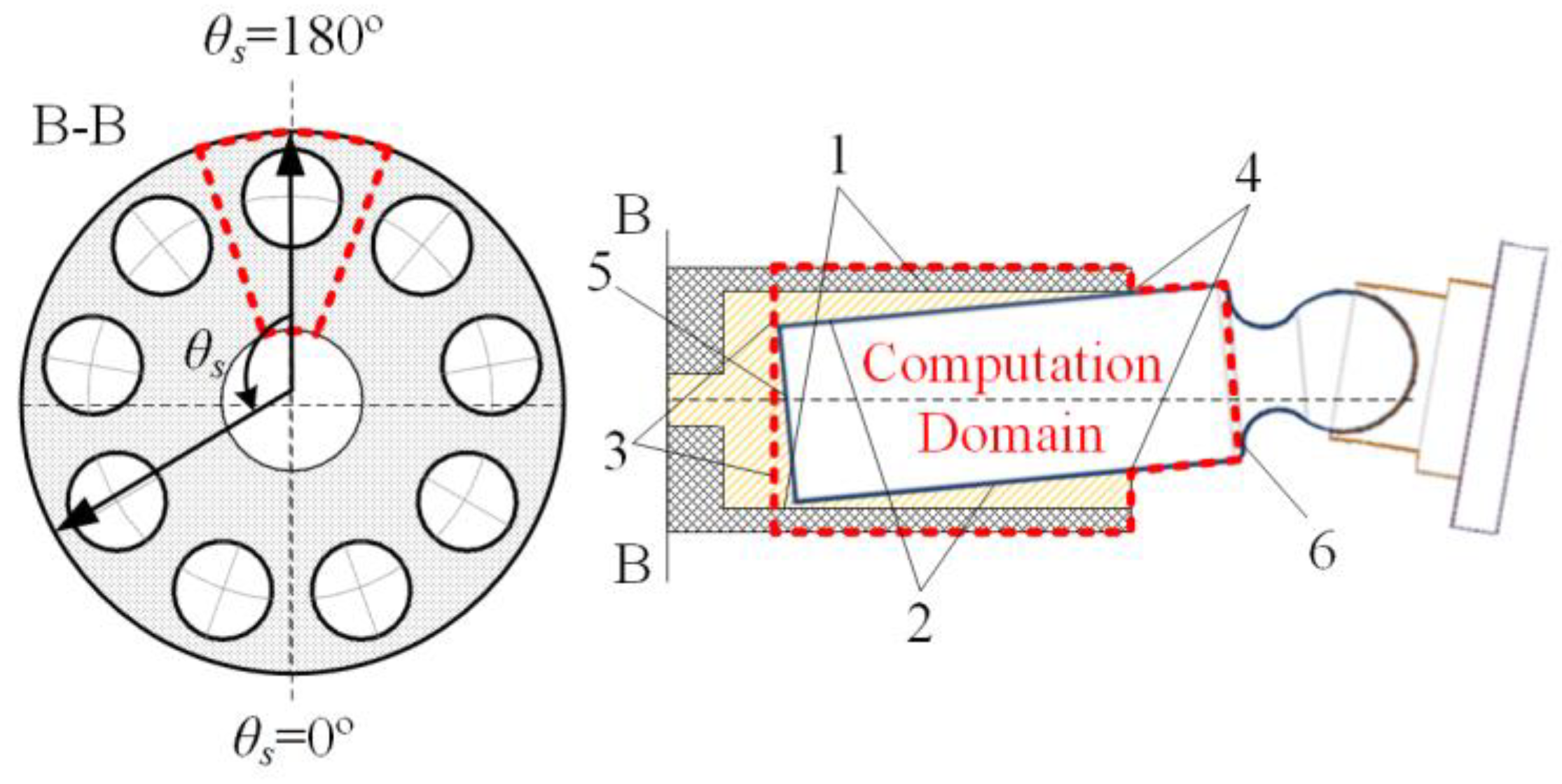
To simplify the model, only one piston/cylinder interface was considered. This piston/cylinder formed the system boundary of the thermal calculation, as shown in Figure 3. Because the nine piston/cylinder interfaces were symmetrical around the distribution circle, the behavior of these interfaces could be expected to be almost the same. For this reason, it was here considered reasonable to choose one interface as a representative. The numbers here represent the corresponding boundaries as labeled in Figure 3.
The boundary conditions of fluid mechanics equations (Reynolds equation) are shown in Equation (8):
where Psuc is the output pressure of the pump when the piston is in the oil suction area (θs = 0°–180°), Pdis is the output pressure of the pump when the piston is in the oil discharge area (θs = 180°–360°), and Pcase is the case pressure of the pump.
The boundary conditions of thermal analysis are the environmental temperature and temperatures of the medium at the inlet and outlet temperatures. For one piston/cylinder interface, solving the energy equation of fluid and heat conduction equation of solid covers the changes in heat in one phase and between two phases. For each specific boundary, the following boundary conditions are defined. The numbers here represent the corresponding boundaries as labeled in Figure 3.
- (1)
- On the film-cylinder interface:
- (2)
- On the film-piston interface:
- (3)
- Oil on the bottom edge of the film:where Tmix is the mixing temperature, which is determined based on the energy balance [19].
- (4)
- Oil on the top edge of the film:where Tin is inlet temperature of oil.
- (5)
- On the bottom surfaces of the piston:where η is piston convection heat transfer coefficient.
- (6)
- On the top of the piston:
Once the oil film temperature distribution was determined, mechanical analysis could progress.
2.3. Deformation Equation
For an accurate description of thermodynamic behavior of piston/cylinder interface, it is not sufficient to just solve the energy and Reynolds equation, but one also needs to consider deformation due to temperature and pressure. In this paper, the deformation matrix method was used to calculate the elastic deformation and thermal deformation of metal parts. The deformation equations are shown in Equation (15) [20]:
where hE is the elastic deformation, pf,g is the oil pressure at node (f, g), pc|f,g is the contact pressure, which is zero in this case, because the piston bears no force in the initial free case, is the elastic deformation matrix, which represents the displacement of node (i, j) caused by the unit load acting on the node (f, g).
Similarly, hT is the thermal deformation, is the thermal deformation matrix, TP|f,g is the temperature at node (f, g), and Tref is the reference temperature and set to 25 °C.
2.4. Force Analysis
The force must be analyzed to solve motion equations. To clarify the description of force analysis, some definitions are presented in Figure 4.
When the pump is operating, the cylinder block slides over the valve plate. With the change in position within the distribution circle (θs), the displacement chambers of each piston are connected to the low-pressure port (θs = 0°–180°) or the high-pressure port (θs = 180°–360°). The pistons were joined to the slippers that glided over the swash plate. By changing the swash plate angle β, the piston stroke s could be adjusted. θs, lt, and s were subject to Equation (16).
The loads acted on the piston in the cavity of piston/cylinder interface in the specific coordinates system is shown in Figure 5.
Because of the overturning angle α, the velocity of piston ṡ had a component normal to the ω, so the Coriolis force Fc took place. With the movement of cylinder block around the shaft, the centrifugal force Fu acted on the center of gravity of the piston. Because the piston movement took place within six degrees of freedom, there was also the inertia force in z-direction Fi and the inertia moment Mi. All these forces acted on the center of gravity and were defined using Equation (17):
The swash plate was removed for the calculation of acting force of slipper Fs. Fs was resolved through the force equilibrium equation in the x-direction. Fs was decomposed into the y-direction and z-direction as presented in Equation (18):
The pressure force Fp was calculated using the pressure of displacement chamber Pc, which differed between the low-pressure port (θs = 0°–180°) and the high-pressure port (θs = 180°–360°):
The acting force of oil was normal to the piston surface and is defined as follows:
Due to the movement of piston, the friction of oil Ff acted on the piston. Ff was calculated using Equation (21):
Because the forces defined by Equations (17) and (19) acted through the center of gravity of the piston, their resultant moments were all zero. This left the moments produced by Fs, Fo, and Ff, which can overturn the piston. These moments were calculated using Equations (22)–(24):
where p(x,z) in Equations (20), (21), (23) and (24) is the pressure distribution obtained by Section 2.1. h(x,z) will be determined in Section 2.6.
Assuming the vector sum of forces and moments are Fsum and Msum.
2.5. Movement Analysis
The movement of the piston was analyzed during force analysis. According to Newton’s second law, several types of force were identified. They are shown in Equation (26).
2.6. Calculation of the Thickness of the Oil Film
The thickness of the oil film h(x,z) was determined as described below.
As shown in Figure 6, supposing that the space between the piston and cavity was filled with an oil film, the thickness of that oil film distribution could be determined according to the geometry characteristics of piston and cavity. In section C-C, O1 was the center of the cavity, O1′ was the projection of O1 on the y axis and O2 was the center of piston, assuming that the piston overturning angle was α and projection of eccentric distance at bottom of piston e on y axis was e0. Piston shaft and cavity shaft intersected in the position (0, 0, l1)|(x,y,z). The following geometric relationships were established:
For an arbitrary cross section C-C of piston, O1 and O2 were used to define a straight line that crossed the surface of the piston at P1 and crossed the cavity surface at P2. Any position on surface of piston P1 could correspond to the circumferential angle θ. |P1P2| was the thickness of the oil film, whose value is here written as . In order to simplify the calculation, there was a transformation of system of coordinates. As shown in Figure 6b, O2 was located at (0, 0, z) and O1 at (-e2, -e1, z). e1 and e2 were subject to Equation (28):
In this way, the algebraic expression of straight line determined by O1O2 was as follows:
On the cross section C-C, cavity was an ellipse, and the piston was a circle. Their algebraic expression was as shown in Equation (30):
The coordinates of P1 and P2 were determined by solving Equations (29) and (30) simultaneously. The results are presented in Equations (31) and (32):
Oil film thickness under specific overturning angle α was determined using the coordinates of P1 and P2:
Along with the elastic and thermal deformations, oil film thickness should be written as:
3. Simulation Algorithm and Conditions
Simulation of the thermodynamic behavior of the piston requires knowledge of the eccentric position, velocity of the piston, and all forces acting on it. Among these, eccentric position and forces are profoundly influenced by temperature distribution within the gap. An iterative method for the simultaneous calculation of all the requirements was here developed. Figure 7 shows a diagram of these calculations.
With constant inlet and outlet pressure, the velocity distribution is considered constant and a basic condition of the Reynolds equation. When the velocity results were considered as the input of energy equation, the temperature distribution indicated by resolving of energy equation was the temperature distribution of oil film in steady state. The mechanical analysis was completed considering hydrodynamic forces and temperature distribution as inputs of motion equations. Using the overrelaxation iterative formula of the finite difference method, the Reynolds equation and the energy equation are solved by programming in MATLAB. If the absolute error of the results on all interior points obtained by two adjacent iterations is not greater than that of the prescribed error, then the iterative solution is considered to be convergent.
An axial piston pump with nine pistons was here selected for study. To start the simulation, some fundamental conditions were defined, which were the structure and working parameters of the pump, the material properties and thermal coefficients of the piston/cylinder interface, and the pressure of displacement chamber.
The structure and working parameters of a specific type of pump are presented in Table 1.
4. Results and Discussion
A simulation of the chosen piston pump was conducted with the model and numerical algorithm introduced in this paper.
In order to validate the developed model in this article, the simulated velocity and temperature distribution were compared with the experiment performed by Pelosi [22]. Constant inlet and outlet pressures on both sides of the piston when the pump was in normal operation were 16 bar (θs = 0°–180°) and 225 bar (θs = 180°–360°) (boundary z = 0 in Figure 8) and 5 bar (boundary z = 1 in Figure 8) respectively. For the temperature simulation, the input parameters were same as Pelosi [22], which are 57.5 °C for the case temperature, 48 °C for temperature at high pressure port, and 43 °C for temperature at low pressure port.
We selected the state where lt = l0, where the piston was in the position of θs = 0° on the distribution circle, and the whole piston was in the cylinder, The corresponding α = 0.0067°. Figure 8 shows the velocity distribution of oil film at the interface of the oil and the piston. Figure 9a shows the result of thermal simulation, and Figure 9b shows the measurement result of the oil film at the interface of the oil and the piston carried by Pelosi [22]. Thus, we can conclude that the model could describe the oil temperature distribution, with reference to previous research.
Results indicated that the velocity distribution of oil film in piston/cylinder interface was affected not only by the relative velocity between piston and cylinder in the form of sinusoidal wave (z direction) but also the rotation of piston (x direction). The motion of the piston would lead the oil to follow its motion, and the change of the velocity direction of the oil would have hysteresis because of the viscous effect, so the vortex would be produced.
Analysis of the Figure 8 also showed that the velocity of flow near the boundaries (z = 0 and z = 1) was faster than in the middle.
Comprehensive analysis of the contents of Figure 8 and Figure 9 indicated that heat transfer was faster where the velocity was faster. Temperature diffused along the velocity, whether the temperature was high or low. This indicated that the accurate calculation of the velocity distribution was very important to the calculation of temperature distribution, considering the velocity has a highly significant effect on temperature diffusion.
The higher temperature region corresponded to a region where the fluid film was thinner, where more heat was generated. In these areas, the oil film tended to become thinner in next time step because high temperature reduced the carrying capacity of oil under the condition of lower viscosity. The eccentricity may be increased, but it still depended on the structure and the pressure in the chamber.
5. Analysis of Thermal Effect
With the thermal results, it was possible to calculate the fluid pressure and piston motion in the piston/cylinder interface. In order to investigate the effect of inlet oil temperature on the lubricating characteristics of oil film, we used the model proposed in this paper to simulate the movement of the bottom of piston in the chamber at different inlet temperatures. To facilitate the simulation, we assumed that the temperatures at high pressure port and low pressure port were the same as the inlet temperature Tin, and the Tin of the six simulations was 20 °C, 40 °C, 60 °C, 80 °C, 100 °C, and 140 °C respectively, and the case, temperature Tc was always 50 °C.
Figure 10 presents simulated trajectory of the piston bottom in the cavity over one shaft revolution with different inlet temperatures. The following conclusions can be summarized:
(1). When the piston rotates within the suction zone (θs = 0°–180°), the oil pressure of the cylinder cavity is smaller, therefore the oil film supporting force is smaller, and the radial movement of the piston intensifies under the same inertial force compared with the condition when the pistons rotates into the outlet zone (θs = 180°–360°). The reduction of the eccentricity during the discharge area is caused by the very high pressure difference between the cylinder and the ambient pressure.
(2). With the increase of oil inlet temperature, the contact time between piston and cavity becomes longer and longer.
These results show that when the pump is operating, the eccentricity appears to be up and down with the changes of piston position in the distribution circle. The bottom of piston makes physical contact with the cylinder during a large part of the operating time, there will be more energy consumption.
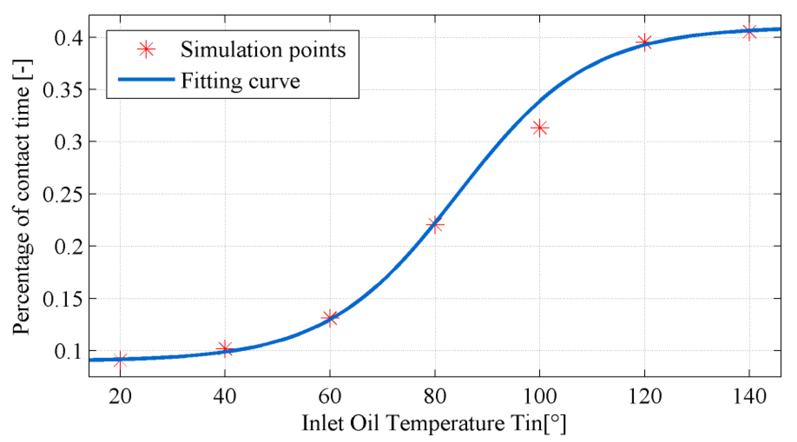
According to the six simulation results, the curve of contact time with the inlet oil temperature is fitted out (see Figure 11). In general, there should be a positive correlation between contact time and solid friction. Therefore, the contact time is regarded as a simple measurement of solid friction, the longer the contact time, and the more the energy consumption. From our analysis, it is concluded that this relationship between contact time and inlet oil temperature should be expressed by Equation (35). The values A, B, C and D are constants, which are determined by the material properties, physics and operating conditions of the sliding pair and lubricating oil and can be obtained by the simulation method presented in this paper. In this case, A = 0.15, B = 0.04, C = −84.37, and D = 0.25. The R-square for the fitting, analyzed by MATLAB, is 0.97.
Figure 11 shows that the contact time increased with the increase of inlet oil temperature, and the growth rate increased first and then decreased, but would not increase all the time. From 20°C to 60°C, the contact time increased slowly and the temperature did not have much effect on the movement of the piston. From 60 °C to 100 °C, the contact time increased by a large margin, which may be due to the decrease in viscosity as the temperature continues to increase, resulting in a significant decrease in the bearing capacity of the lubricant film. The piston is in continuous contact with the cylinder under the action of centrifugal force. After 100 °C, the contact time between the piston and the cylinder will finally reach a balance due to the constraints of the structure of piston/cylinder interface and the working conditions (pressure).
6. Conclusions
A numerical multi-discipline modeling method suitable for describing the lubricant oil film characteristics in piston pump has been developed. The results of velocity field and temperature field are accurate compared with the experiment. Considering the thermal effect, the quantitative relationship between oil inlet temperature and contact time between piston and cylinder is obtained in this paper, and it is shown that the relationship is a hyperbolic tangent. Thus, it can be predicted when and where the contact will appear under different temperature conditions. This method can be helpful when it refers to the design and analysis of a piston pump.
In this paper, we consider the thermal effect on the oil film characteristics. In the future, we would include the oil pressure, axis rotate speed and the cavitation in the model and analyze all these factors’ effects on the pump operation performance, such as oil leakage and pressure fluctuation. We will also establish a test rig to verify the simulation results.
Author Contributions
Conceptualization, Yueheng Song and Jiming Ma; Methodology, Formal Analysis, Investigation and Writing-Original Draft Preparation, Yueheng Song; Writing-Review & Editing, Supervision and Project Administration, Shengkui Zeng.
Funding
This research received no external funding.
Conflicts of Interest
The authors declare no conflict of interest.
References
- Yang, H.Y.; Ding, F.; Yang, X.P.; Lu, Q. Hydraulic power systems for trunk line aircrafts. China Mech. Eng. 2009, 18, 2152–2159. [Google Scholar]
- Cai, Z.B.; Zhou, Y.; Qu, J. Effect of oil temperature on tribological behavior of a lubricated steel–steel contact. Wear 2015, 332–333, 1158–1163. [Google Scholar] [CrossRef]
- McCallon, H.; Yousif, F.; Lloyd, T. The analysis of thermal effects in a full journal bearing. J. Lubr. Technol. 1970, 92, 578–587. [Google Scholar] [CrossRef]
- Ferron, J.; Frene, J.; Boncompain, R.A. Study of the thermohydrodynamic performance of a plain journal bearing comparison between theory and experiments. J. Lubr. Technol. 1983, 105, 422–428. [Google Scholar] [CrossRef]
- Rohde, S.M.; Oh, K.P. A thermoelastohydrodynamic analysis of a finite slider bearing. J. Lubr. Technol. 1975, 97, 450–460. [Google Scholar] [CrossRef]
- Mi, J.T.; Meng, Y.G. THD analysis of rolling piston and journal bearings in rotary compressors. Tribol. Trans. 2016, 59, 195–207. [Google Scholar] [CrossRef]
- Cheng, F.; Ji, W. A velocity-slip model for analysis of the fluid film in the cavitation region of a journal bearing. Tribol. Trans. 2016, 97, 163–172. [Google Scholar] [CrossRef] [Green Version]
- Lu, P.; Zheng, X.; Li, W.; Yang, P.; Huang, H.; Yu, Y. A thermal-fluid coupling numerical study on the characteristics of air-oil two phase flow and heat transfer in a micro UAV bearing chamber. RSC Adv. 2017, 7, 44598–44604. [Google Scholar] [CrossRef]
- Braun, M.J.; Hannon, W.M. Cavitation formation and modelling for fluid film bearings: A review. J. Eng. Tribol. 2016, 224, 839–863. [Google Scholar] [CrossRef]
- Chan, C.W.; Han, Y.F.; Wang, Z.; Wang, J.; Shi, F.; Wang, N.; Wang, Q.J. Exploration on a fast ehl computing technology for analyzing journal bearings with engineered surface textures. Tribol. Trans. 2014, 57, 206–215. [Google Scholar] [CrossRef]
- Gels, S.; Murrenhoff, H. Simulation of the lubricating film between contoured piston and cylinder. Int. J. Fluid Power 2010, 11, 15–24. [Google Scholar] [CrossRef]
- Ma, J.M.; Chen, J.; Li, J.; Li, Q.L.; Ren, C.Y. Wear analysis of swash plate/slipper pair of axis piston hydraulic pump. Tribolo. Int. 2015, 90, 467–472. [Google Scholar] [CrossRef]
- Olems, L. Investigations of the temperature behaviour of the piston cylinder assembly in axial piston pumps. Int. J. Fluid Power 2000, 1, 27–39. [Google Scholar] [CrossRef]
- Ivantysynova, M.; Huang, C.C.; Andreas, J.J. Determination of Gap Surface Temperature Distribution in Axial Piston Machines. In Proceedings of the ASME International Mechanical Engineering Congress and Exposition, Chicago, IL, USA, 5–10 November 2006. [Google Scholar]
- Kazama, T. Thermohydrodynamic lubrication model applicable to a slipper of swashplate type axial piston pumps and motors (Effects of operating conditions). Tribol. Online 2010, 5, 250–254. [Google Scholar] [CrossRef]
- Pelosi, M.; Ivantysynova, M. The impact of axial piston machines mechanical parts constraint conditions on the thermo-elastohydrodynamic lubrication analysis of the fluid film interfaces. Int. J. Fluid Power 2013, 14, 35–51. [Google Scholar] [CrossRef]
- Zecchi, M. A Novel Fluid Structure Interaction and Thermal Model to Predict the Cylinder block—Valve Plate Interface Performance in Swash Plate Type Axial Piston Machines. Ph.D. Thesis, Purdue University, West Lafayette, IN, USA, December 2013. [Google Scholar]
- Wen, S.Z.; Huang, P. Principle of Tribology, 4th ed.; Tsinghua University Press: Beijing, China, 2012. [Google Scholar]
- Khonsari, M.M.; Wang, S.H. On the fluid-solid interaction in reference to thermoelastohydrodynamic analysis of journal bearings. J. Tribol. 1991, 113, 398–404. [Google Scholar] [CrossRef]
- Zhang, Z. Analysis of the Thermohydrodynamic Performance of Dynamically Loaded Bearings in Consideration of Non-Netonian, Derformation and Surface Topography. Ph.D Thesis, Shanghai Jiao Tong University, Shanghai, China, 2014. [Google Scholar]
- Yang, S.M.; Tao, W.S. Heat Transfer, 4th ed.; Higher Education Press: Beijing, China, 2006. [Google Scholar]
- Pelosi, M.; Ivantysynova, M. A Novel Thermal Model for the Piston/Cylinder Interface of Piston Machines. In Proceedings of the ASME Dynamic Systems and Control Conference, Hollywood, CA, USA, 12–14 October 2009. [Google Scholar]
Figure 1.
Sliding pairs in axial piston pump.

Figure 2.
Definitions of coordinates and gap height.

Figure 3.
Computation domain and boundary.

Figure 4.
Definitions used for mechanical analysis.

Figure 5.
Graph of mechanical analysis.

Figure 6.
Graph of calculation of oil film thickness: (a) Axial section view; (b) Bottom view.

Figure 7.
Flow chart of calculation.

Figure 8.
Velocity distribution.

Figure 9.
(a) Simulated temperature distribution; (b) Measured temperature distribution by experiment [22].
Figure 9.
(a) Simulated temperature distribution; (b) Measured temperature distribution by experiment [22].

Figure 10.
Simulated trajectory of the piston bottom in the cavity over one shaft revolution with different inlet temperatures.
Figure 10.
Simulated trajectory of the piston bottom in the cavity over one shaft revolution with different inlet temperatures.

Figure 11.
Curve of contact time with oil inlet temperature.


Table 1.
Structure and working parameters.
| Parameter | Value |
|---|---|
| Number of pistons | 9 |
| Rated working pressure | 225 bar |
| Rated rotation speed | 1000 rpm |
| Distribution circle diameter | 80 mm |
| Piston diameter | 30.14 mm |
| Cylinder cavity diameter | 31.2 mm |
Table 2.
Material properties.
| Density (kg/m3) | Young Modulus (Gpa) | Specific Heat Capacity (J/(kg⋅K)) | Heat Conductivity (W/(m⋅K)) | Viscosity (20°C) (Pa⋅s) | Heat Convection Coefficient (W/(m2⋅K)) | |
|---|---|---|---|---|---|---|
| Cylinder | 8100 | 130 | 390 | 41.9 | / | / |
| Piston | 7850 | 210 | 490 | 50.28 | / | 50 |
| Oil | 862.1 | / | 1880 | 0.143 | 0.15 | / |
© 2018 by the authors. Licensee MDPI, Basel, Switzerland. This article is an open access article distributed under the terms and conditions of the Creative Commons Attribution (CC BY) license (http://creativecommons.org/licenses/by/4.0/).
Share and Cite
MDPI and ACS Style
Song, Y.; Ma, J.; Zeng, S. A Numerical Study on Influence of Temperature on Lubricant Film Characteristics of the Piston/Cylinder Interface in Axial Piston Pumps. Energies 2018, 11, 1842. https://doi.org/10.3390/en11071842
AMA Style
Song Y, Ma J, Zeng S. A Numerical Study on Influence of Temperature on Lubricant Film Characteristics of the Piston/Cylinder Interface in Axial Piston Pumps. Energies. 2018; 11(7):1842. https://doi.org/10.3390/en11071842
Chicago/Turabian StyleSong, Yueheng, Jiming Ma, and Shengkui Zeng. 2018. "A Numerical Study on Influence of Temperature on Lubricant Film Characteristics of the Piston/Cylinder Interface in Axial Piston Pumps" Energies 11, no. 7: 1842. https://doi.org/10.3390/en11071842
Note that from the first issue of 2016, this journal uses article numbers instead of page numbers. See further details here.