Article

A Novel Two-Stage Photovoltaic Grid-Connected Inverter Voltage-Type Control Method with Failure Zone Characteristics

1
Key Laboratory of Distributed Energy Storage and Micro-grid of Hebei Province, North China Electric Power University, Baoding 071003, China
2
State Grid Liaoning Electric Power Research Institute, Shenyang 110006, China
3
China Electric Power Research Institute (CEPRI), Beijing 100192, China
4
State Grid Beijing Electric Power Company, Beijing 100031, China
*
Author to whom correspondence should be addressed.
Energies 2018, 11(7), 1865; https://doi.org/10.3390/en11071865
Submission received: 16 May 2018 / Revised: 22 June 2018 / Accepted: 13 July 2018 / Published: 17 July 2018
(This article belongs to the Special Issue Power Electronics in Renewable Energy Systems)

Abstract

:
This paper investigates how to develop a two-stage voltage-type grid-connected control method for renewable energy inverters that can make them simulate the characteristics of a synchronous generator governor. Firstly, the causes and necessities of the failure zone are analyzed, and thus the traditional static frequency characteristics are corrected. Then, a novel inverter control scheme with the governor’s failure zone characteristics is proposed. An enabling link and a power loop are designed for the inverter to compensate fluctuations and regulate frequency automatically. Outside the failure zone, the inverter participates in the primary frequency regulation by disabling the power loop. In the failure zone, the droop curve is dynamically moved to track the corrected static frequency characteristic by enabling the power loop, resisting the fluctuation of grid frequency. The direct current (DC) bus voltage loop is introduced into the droop control to stabilize the DC bus voltage. Moreover, the designed dispatch instruction interface ensures the schedulability of the renewable energy inverter. Finally, the feasibility and effectiveness of the proposed control method are verified by simulation results from MATLAB (R2016a).

Graphical Abstract

1. Introduction

Energy consumption rises as the development of global industrialization, resulting in more usage of fossil fuels [1]. Carbon dioxide emissions caused by fossil fuels accelerate global warming, leading to serious environmental problems [2]. In order to replace the energy generated by fossil fuels, photovoltaic (PV) power generation systems can be used [3]. For such PV power generation systems, it is important to design a grid-connected inverter that provides reliable AC (alternating current) power to the grid from the PV source’s DC (direct current) power [4]. Grid integration of inverters has become increasingly important in distributed generation (DG) systems [5,6]. Many different types of PV inverters have been researched and proposed [7,8]. Generally, when it comes to the topology of photovoltaic grid-connected circuits, there are two types: single-stage inverters and two-stage inverters. The single-stage inverter is simple in structure, but it requires a high input voltage. Many PV modules are used to boost the required high voltage, which have several defects such as the imbalance of hot spots during partial shading, low safety features, and the poor maximum power point tracking (MPPT) performance [9]. Thus, a DC-DC power-conversion structure which can increase the low PV-source voltage to a high DC-bus voltage was introduced to the single-stage inverter. Inverters with above configuration are named two-stage inverters, which can use the MPPT algorithm more efficiently [10,11,12,13,14]. Therefore, two-stage inverters have the advantage of fewer series-connected PV modules and better MPPT performances in comparison with single-stage inverters.
In the grid-connected mode, the inverters are controlled as current sources [15,16]. In the island mode, there is no grid connection to regulate voltage and frequency profiles, and the inverter is required to determine the voltage and frequency of system, so the inverter generally adopts voltage-type control [17]. Transitions between operation modes can cause deviations in voltage and current, because of the mismatch in frequency, phase of the inverter output voltage and those of the grid voltage [18]. If a voltage-type control structure can still be used in the grid-connected mode, the mode switching process can be avoided and the above problem will be effectively mitigated and eliminated.
Droop control is a voltage control method, which is usually applied to the parallel connection of inverters in distributed uninterruptible power supply systems to provide voltage support for the micro-grid on island mode. Considerable research efforts have been devoted to inverter’s voltage-type grid-connected control. De Paiva, et al. [19] added an extra phase loop to traditional droop control, which improved the system’s dynamic response and maintained suitable damping performance. Avelar, et al. [20] proposed an improved design of the polynomial model mentioned in [19] and presented a state equation model of an inverter connected to the grid with droop control. However, these methods are suitable for simple single-phase inverters instead of the widely used three-phase inverters. Verma, et al. [21] presented a model of a grid connected inverter operating in grid supporting mode incorporating dynamics of droop control. However, this method does not consider the two-stage application topology combined with PV energy sources. Additionally, none of those control strategies proposed consider fluctuations of the power grid such as fluctuations of grid voltage and frequency.
Recently, the penetration rate of renewable energy generation in the power system has gradually increased. Renewable energy generation is replacing the traditional generation, and it should gradually be equipped with the regulation ability of traditional generators. Therefore, it is a trend for renewable energy sources to share frequency regulation duties on the grid. Zhong [22] proposed the concept of a power electronics-enabled autonomous power system design. This scheme provides a uniform interface mechanism so that renewable energy sources can participate in grid frequency regulation like conventional power supplies. To this end, Yan, et al. [23] combines the droop characteristics and the Virtual Synchronous Generator (VSG) to make the PV storage two-stage inverter have primary frequency regulation characteristics. However, they do not take into account the governor’s failure zone. Moreover, their study is based on energy storage, which is uneconomical. In summary, the establishment of a voltage-type two-stage grid-connected photovoltaic system that simulates the characteristics of the failure zone of the synchronous generator governor is of great significance for increasing penetration rate of photovoltaic power generation.
In this paper, the power control scheme of the inverter under the low-voltage line parameters is firstly obtained. Then, starting from the physical structure of the governor, the causes and the necessities of the failure zone and its effect on the frequency regulation are analyzed, and the static frequency characteristics are corrected. Finally, a novel two-stage photovoltaic grid-connected inverter voltage-type control method with the failure zone characteristics is proposed. By enabling the power loop inside the failure zone and disabling the power loop outside the failure zone, the inverter dynamically compensates grid fluctuations and participates in grid frequency regulation. The design of the dispatch interface ensures the schedulability of the inverter. DC voltage loop stabilizes the DC bus voltage, allowing the system to operate without energy storage.

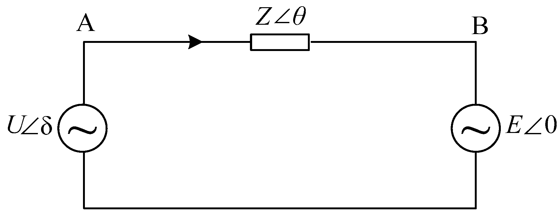
2. Power Transmission Characteristics of Grid-Connected Inverter

The grid-connected equivalent circuit of the voltage-type inverter is shown in Figure 1. As shown in the figure, both the inverter and the grid are simplified to a voltage source. U δ is the output voltage of the inverter after the filter. E 0 is the grid voltage (since the grid capacity is much larger than the inverter capacity, E can be considered as a constant). Z θ is the impedance between the inverter and power grid.
According to the theory of power system analysis, the current flowing through the terminal is:
I ˙ = U δ E 0 Z θ = U cos δ E + j U sin δ Z θ
The output active power and reactive power of the inverter is expressed as:
P = ( E U Z cos δ E 2 Z ) cos θ + E U Z sin δ sin θ Q = ( E U Z cos δ E 2 Z ) sin θ E U Z sin δ cos θ ,
where, δ is the power angle.
The studied subject in this paper is a small and medium-sized photovoltaic power generation system, which is usually connected to a low-voltage distribution network. The low-voltage power transmission line is mostly resistive [24]. Therefore, in this scenario, θ 0 , so sin θ 0 and cos θ 1 . For a resistive impedance, θ = 90°. Bring it into Equation (2), Equation (3) can be obtained as:
P = E U Z cos δ E 2 Z Q = E U Z sin δ
In addition, δ is generally very small, so we have sin δ 0 and cos δ 1 . Bring the above approximate values into Equation (3), it can be obtained that:
P U Z E E 2 Z Q E U Z δ
Roughly, Equation (4) can be written as:
P ~ U Q ~ δ ,
where ~ means in proportion to. Therefore, the conventional droop control strategy can be obtained as:
U = U r k p ( P P r ) ω = ω r + k q ( Q Q r )
Due to f = ω 2 π , Equation (6) can be rewritten as:
U = U r k p ( P P r )   f = f r + k q ( Q Q r ) ,
where U is the reference amplitude of the inverter’s output voltage, f is the frequency reference value of the inverter, U r is the amplitude of the inverter’s rated output voltage, f r is the rated frequency of the inverter, k p is the droop coefficient of the inverter’s active power, k q is the droop coefficient of the inverter’s reactive power, P is the active power output by the inverter, Q is the reactive power output by the inverter, P r is the rated active power of the inverter, Q r is the rated reactive power of the inverter.
Equation (7) indicates that P is approximately linear with U and Q is approximately linear with f . Therefore, by controlling the amplitude and phase of the output voltage of the inverter, decoupled control of the active and reactive power of the inverter can be realized.

3. Failure Zone of Synchronous Generator Governor

3.1. The Cause of Failure Zone

Most steam turbogenerators and hydroturbines in the power system now are equipped with speed governors. The governor’s function is to monitor the generator speed and to control the throttle valves that adjust steam flow into the turbine in response to changes in “system speed” or frequency [25]. During the period of actual operation, due to mechanical friction and overlap, the static characteristics of the generator unit differ from the theoretical static characteristics (see Figure 2). In a frequency range around the rated frequency, the governor does not respond to changes in frequency. This frequency range is defined as the failure zone of the governor.
In Figure 2, the thick solid line is the theoretical static frequency characteristic of the unit, The shaded area is the failure zone, f 0 is the initial frequency of the system, f H is the upper frequency limit of the failure zone, f L is the lower frequency limit of the failure zone, Δ f w is the maximum frequency hysteresis of the governor, Δ P w is the maximum power error of the governor. It should be noted that the failure zone does not exist for a specific frequency or power. On the contrary, the failure zone is ubiquitous, which is determined by the physical characteristics of the synchronous generator governor. From Figure 2, we can see that the failure zone satisfies Equations (8) and (9).
Δ f w = ( f H f L ) / 2 ,
Δ f w Δ P w = k p ,
where k p is the droop coefficient of the inverter’s active power.

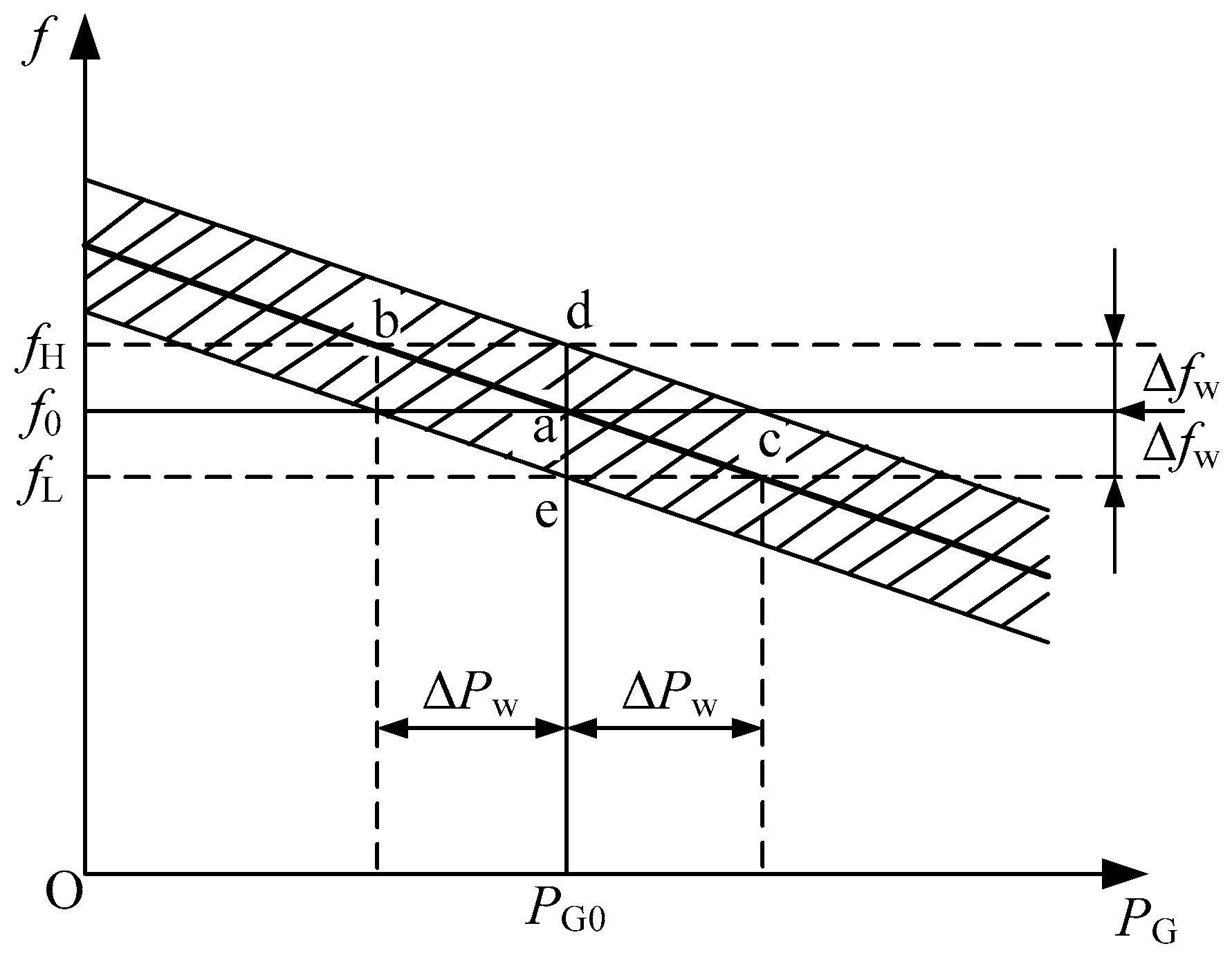
3.2. Static Frequency Characteristics Considering the Failure Zone

This section is a case study of Figure 2, which analyzes the similarities and differences between theoretical static frequency characteristics and actual static frequency characteristics. At the initial state, the system operates at point a, the system frequency is f 0 , and the output active power is P G 0 . For the theoretical static frequency characteristics, the active power generated by the generator will gradually decrease as the grid frequency gradually increases. When the frequency rises to f H , the active power decreases to P G 0 Δ P w and the operating point moves to point b. However, there is a failure zone in the actual static frequency characteristics. When the frequency is slightly increased, the power generated by the generator does not change immediately, but remains at P G 0 . When the frequency rises to f H , the operating point comes to point d, where the governor completely overcomes friction and passes through overlaps. When the frequency continues to increase, the power output from the inverter gradually decreases from P G 0 according to the droop coefficient. The reduced process of the grid frequency is similar to the above process, which is not repeated here.
From Equation (7), it can be seen that under low-voltage line conditions, the frequency is no longer approximately linearly related to the active power, but is approximately linearly related to the reactive power. It should be noted that this type of frequency regulation feature does not exist in conventional generators, but it is widely present in renewable energy inverters connected to low-voltage lines. In general, the system operates stably at rated conditions with f 0 = f N . With reference to the failure zone characteristics of the conventional synchronous generator, the static frequency characteristics of the inverter in the low-voltage lines considering the failure zone are obtained (see Figure 3).
where Q I is the reactive power of the inverter and Δ Q w is the maximum error reactive power of the inverter. The meanings of other variables are consistent with those of Figure 2.

3.3. The Effect of Failure Zone on Frequency Regulation

From the above analysis, it can be seen that the failure zone will shift the theoretical static frequency characteristics, resulting in a “dull” frequency regulation process, which is caused by the physical characteristics of the mechanical hydraulic governor. However, with the advancement of technology, in sensitive governors (such as electro-hydraulic governors), it is necessary to set the failure zone manually. If there is no failure zone or the failure zone is too small, when the frequency of the power system fluctuates, the governor will act unnecessarily, which is not conducive to the healthy operation of synchronous generators/inverters and the frequency stability of the power system. In addition, the failure zone should not be too large. Otherwise, synchronous generators/inverters will lose the capability of frequency regulation, and thus they will fail to provide frequency support for the system actively.

4. Novel Two-Stage Voltage-Type Grid-Connected Photovoltaic Inverter Control Method with Failure Zone Characteristics

4.1. Design Logic of Failure Zone

Synchronous generators in the system must set the failure zone according to the guidelines of the grid company, whose prescribed failure zone range is |±0.033| Hz. That is to say, Δfw = 0.033 Hz. According to the relevant rules and droop relationship, the inverter control logic with the failure zone characteristics is designed as shown in Equations (10) and (11):
{ Q = Q N | f g f N | < Δ f w + ξ Q = Q N + ( f g f H ) / k q | f g f N | > Δ f w + ξ ,   f g > f H Q = Q N + ( f g f L ) / k q | f g f N | > Δ f w + ξ ,   f g < f L ,
ξ = f ( λ ) λ [ 0 , 100 % ] ,   ξ 0 ,
where Δ f w is the maximum frequency hysteresis of the governor, λ is the penetration rate of renewable energy in power system, ξ is the frequency regulation delay of the inverter, indicating the degree to which the renewable energy based inverter lags behind the conventional synchronous generators when participating in the frequency regulation. ξ is a function of λ and there is a negative correlation between them qualitatively. In the initial stage of renewable energy development, λ is very small, and there is no need to consider this issue due to the small capacity of renewable energy. As renewable energy sources gradually increase, the power capacity of the power system connected to the inverter increases. Thus, the inverter should have frequency regulation capability. Otherwise, the frequency regulation capability of the entire power grid will gradually decline. When λ is low, the capacity of the inverter power supply and the frequency regulation capability are small, and the frequency regulation technology is undeveloped. Considering the safety and stability of the power grid, inverters should be less involved in frequency regulation than synchronous generators with large capacity and developed technology. Therefore, the concept of frequency regulation delay of the inverter ξ was introduced so that the inverter involved in frequency regulation behind the synchronous generator. With the increase of λ , the control technology will be more advanced, renewable energy sources will be able to gradually share the frequency regulation tasks of the synchronous generators, so ξ will gradually decrease. It should be noted that the λ and ξ that we introduced in the article are both macroscopic and long-time, because the change of λ is very slow (especially for a huge power grid). For theoretical limit case, when λ reaches 100%, ξ = 0 , which means that renewable energy inverters have completely replaced the conventional synchronous generators and are qualified for the frequency regulation. Based on the above analysis, the failure zone threshold of the renewable energy inverter Δ f w is set to Δ f w + ξ . When the frequency deviation is less than Δ f w , the inverter outputs constant power. When the frequency deviation increases beyond Δ f w , the inverter performs frequency regulation through droop control to limit the fluctuation of the frequency in a wider range. Considering that the inverter should still be able to respond to the dispatch instruction, the operation flowchart shown in Figure 4 is designed.

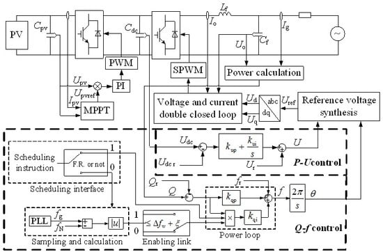
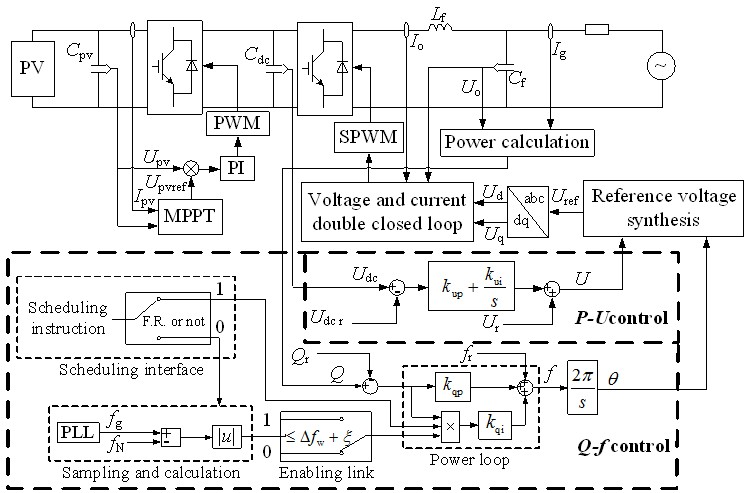
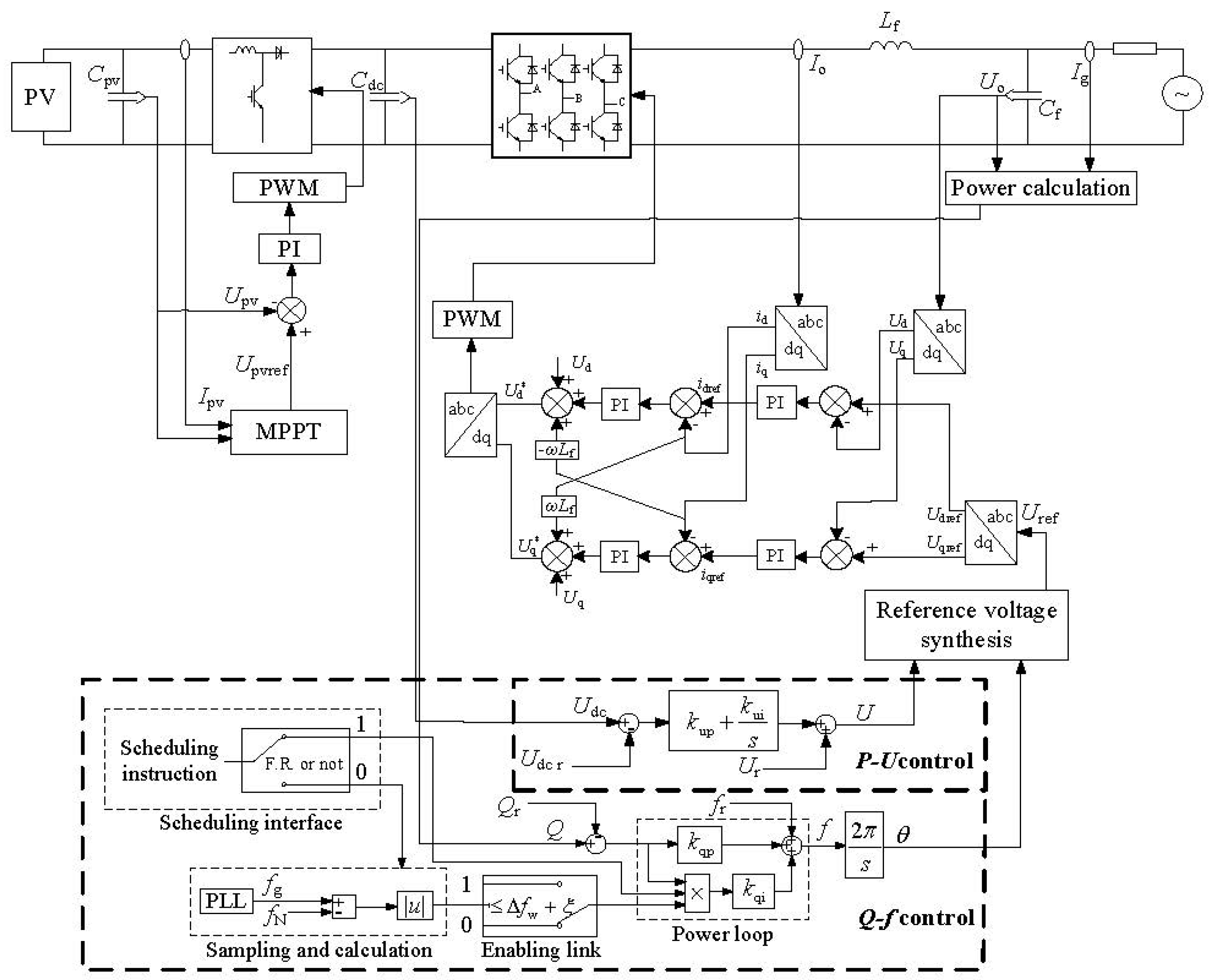
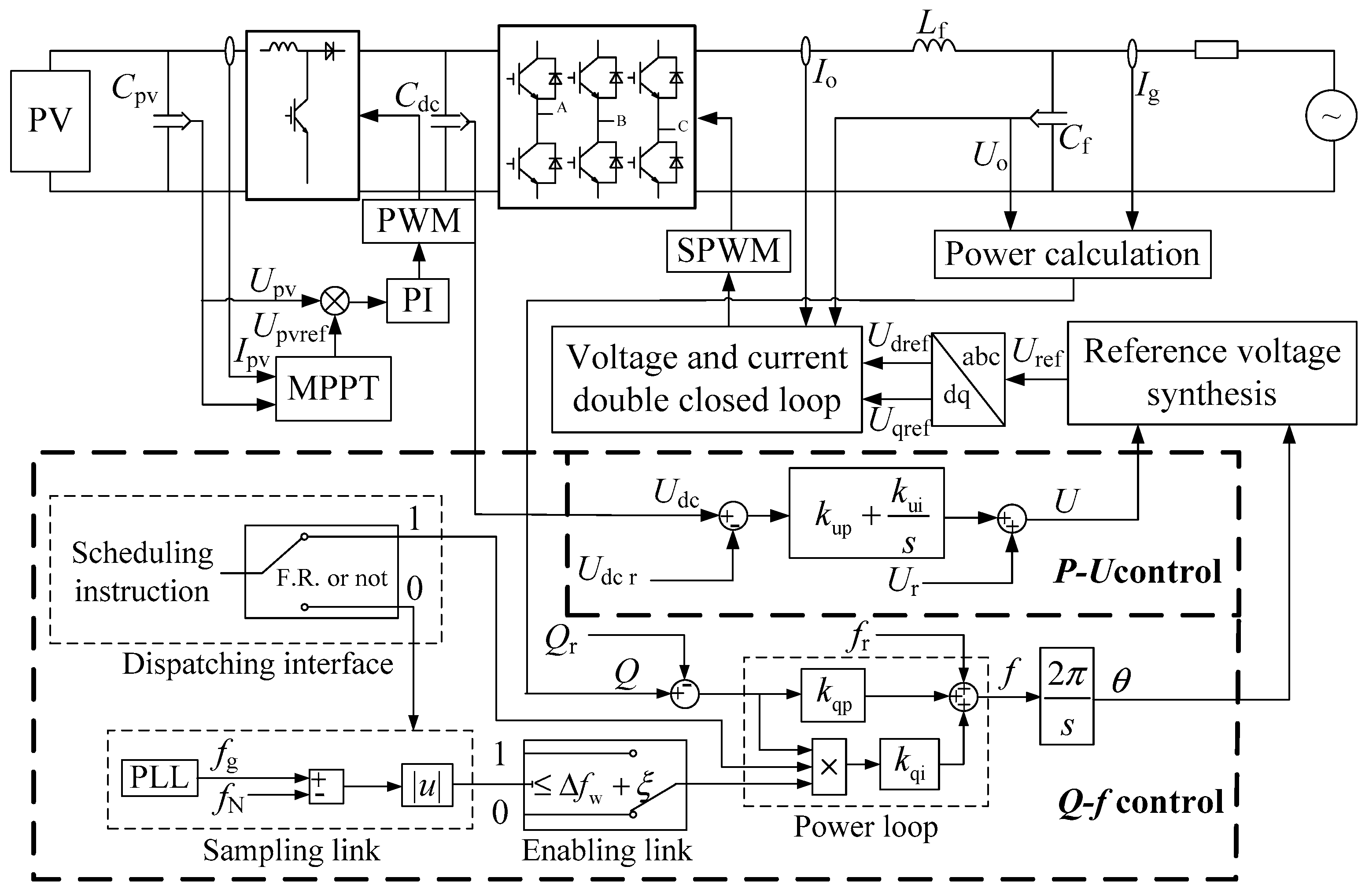
4.2. Novel Two-Stage Photovoltaic Grid-Connected Inverter Voltage-Type Control Method

4.2.1. Active Power-Voltage Control

Considering the economy of operation, the regulation of voltage is generally through balancing locally and near. Therefore, the inverter does not need to adjust the power according to the change of the system voltage, but outputs constant power. An active power loop is formed by adding integral term to the droop control, see Equation (12):
U = U r ( k pp + k pi s ) ( P P r ) ,
where k pp and k pi are the proportional gain and the integral gain of the active power loop, respectively. For ease of analysis, it is assumed that the irradiance does not change during the analysis of the inverter’s active power in this section. For a grid-connected two-stage photovoltaic power generation system, the active power output by the inverter can be reflected by the voltage change on the DC side. In detail, the active power and DC bus voltage satisfy Equation (13):
Δ P = 1 2 C dc Δ U dc 2 ,
where Δ P is the amount of changes of the inverter’s output active power, C dc is the DC bus capacitance, and Δ U dc is the amount of changes of the DC bus voltage. The rated active power corresponds to the rated DC voltage. If the output active power of inverter increases, the DC bus voltage will drop and vice versa. Therefore, we replace P with U dc , replace P r with U dc r , and convert the active power loop in Equation (12) into a DC bus voltage loop, as shown in Equation (14):
U = U r ( k up + k ui s ) ( U dc r U dc )
The control design of the DC voltage loop allows the system to operate without energy storage and maintain a stable active power output when the grid voltage fluctuates.

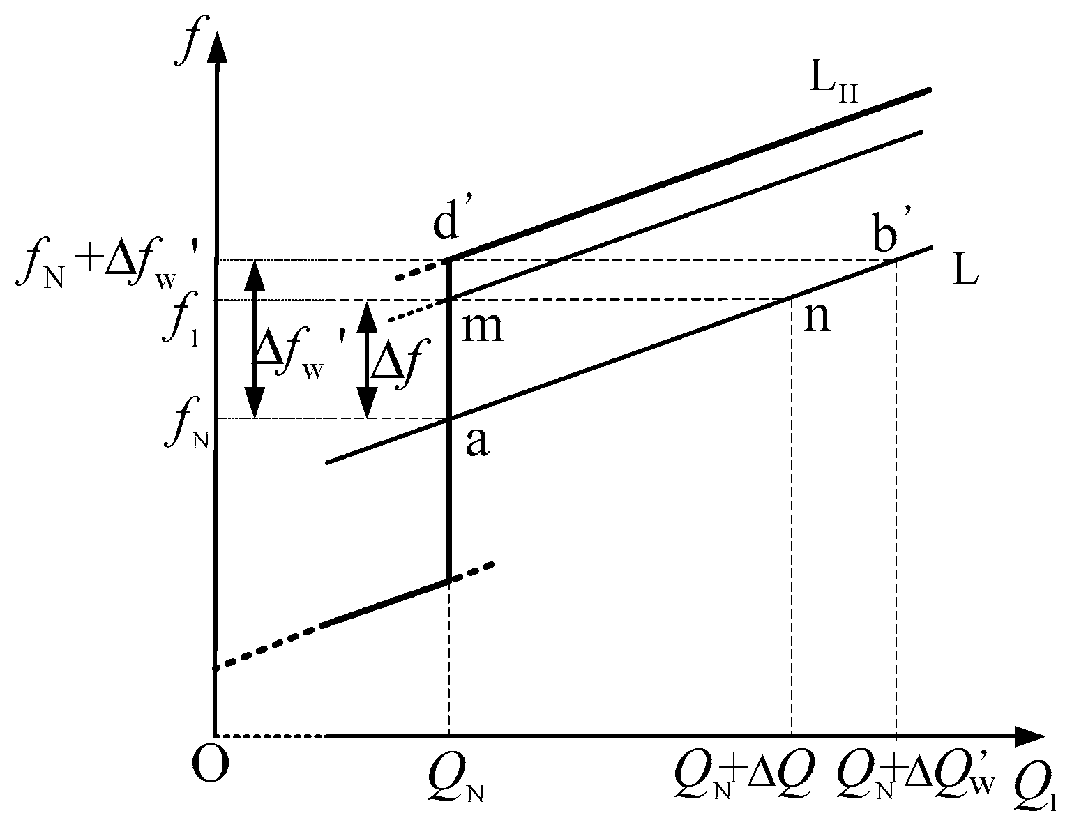
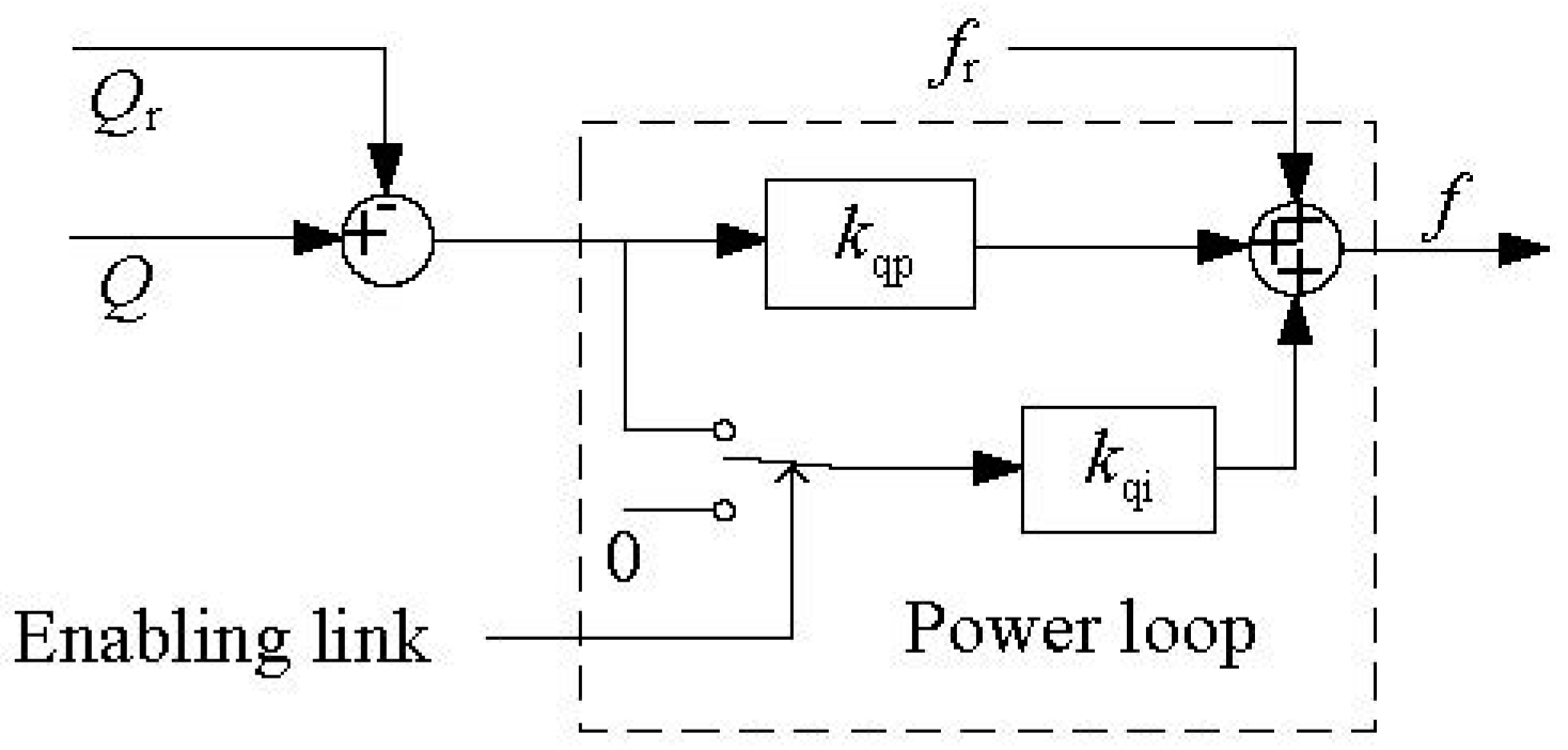
4.2.2. Reactive Power-Frequency Control

In this section, the control method outside the failure zone was introduced first. Then, the control method in the failure zone was introduced. In this section, reactive power-frequency control is introduced. The inverter has different characteristics depending on whether the frequency is in the failure zone. In this section, features outside the failure zone are first introduced. Then, the characteristic in failure zone was introduced.
As mentioned earlier, the inverter designed in this paper is a voltage-type inverter. For this kind of inverter, it is common to regulate frequency through droop control. The inverter in this article is in a mainly resistive scenario, so it follows the droop relationship shown in Equation (7). Therefore, outside the governor’s failure zone, the inverter can regulate frequency through the relationship of Equation (7).
Conversely, in the failure zone, the output power of the inverter should be kept constant to simulate the characteristics of the synchronous generator governor. The regulation principle in the failure zone is shown in Figure 5
In Figure 5, the rated frequency of the system is f N , the rated reactive power of the inverter is Q N , and the initial operating point is point a. When the grid fluctuates slightly and the frequency of the grid rises by Δ f ( Δ f < Δ f w ) to f 1 , the frequency of the inverter is also clamped by the grid at f 1 . For common inverters, according to the theoretical droop characteristic, the reactive power output from the inverter will increase, and the operation point is moved to point n along the line L. In order to control the inverter’s output reactive power as fixed Q N , the straight line L should be shifted upwards by Δ f . During this process, the operating point will be shifted leftwards from point n to point m. Therefore, for any Δ f less than Δ f w , the operating point can be returned to the straight line Q = Q N by shifting the droop characteristic line upwards. In this way, the frequent change of inverter output is avoided, and the effect of the conventional synchronous generator governor failure zone is simulated. Specially, when the frequency change Δ f is equal to Δ f w , the adjusted operating point is point m, and the droop characteristic line is shifted to straight line L H . If the frequency continues to deviate from Δ f w , which indicates a large frequency disturbance, the inverter will participate in the primary frequency regulation according to the droop characteristics shown in L H , and share the frequency regulation duties with the conventional synchronous generators.
In order to make the renewable energy-based inverter simulate the failure zone characteristics of the synchronous generator governor, the reactive power loop and the enabling link are designed so that the inverter will output constant reactive power within the failure zone threshold to achieve the static frequency characteristics shown in Figure 3. Power loop consists of common droop control and an integral term. If the enabling link is enabled, it guarantees a constant power output. If the enabling link is disabled, the inverter still outputs power according to droop relationship. The principle of reactive power-frequency control is shown in Figure 6.

4.2.3. Overall Control Scheme of the Inverter

The above ideas and methods are integrated to obtain a voltage-based control scheme for a two-stage photovoltaic grid-connected inverter with the characteristics of the governor’s failure zone, as shown in Figure 7.
According to the function and control scheme of the inverter, renewable energy based inverter can be divided in grid-feeding inverter, grid-forming inverter and grid-supporting inverter [26]. The grid-forming inverters can set the voltage amplitude and frequency of the local grid. The grid-feeding power inverters are mainly designed to deliver power to an energized grid. A grid-supporting power converter is in between a grid-feeding and a grid-forming power converter [5]. The inverter in this paper is voltage source based grid-supporting inverter, belonging to the grid-supporting inverter. It should be noted that some of control details are omitted or simplified in consideration of the aesthetic appearance of figure, such as coordinate transformation parts and the voltage-current cascaded control part, etc. The complete control block diagram is shown in Figure A1.
As shown in Figure 7, MPPT is implemented through the control of the boost circuit. The MPPT algorithm generates a photovoltaic voltage reference value U pvref , and the PI regulator implements tracking of U pvref . When the solar irradiance changes, the inverter always outputs the maximum photovoltaic energy to ensure the maximum utilization of renewable energy. The inverter output voltage is controlled by the DC bus voltage loop shown in Section 4.2.1. For renewable energy sources connected to the power grid through inverters, their primary frequency regulation function is a new feature and may be undeveloped. Therefore, this function should be controlled by the dispatch of the power system for the stability and controllability of the power system. Therefore, the inverter should work as follows: when the power dispatch requires the inverter to participate in frequency regulation, the inverter decides whether or not to participate in it through the failed zone; when the power dispatch does not require the inverter to participate in a frequency regulation, the inverter always outputs a constant power even if the frequency is outside the failure zone. Therefore, the frequency control structure includes sampling link, dispatching interface, enabling link and power loop. Dispatch instructions can inputted through the dispatching interface.
If the constant power output of the inverter is required according to the dispatching signal, the dispatching interface outputs 1 to enable the power loop and the power output by the inverter tracks reference value.
If the inverter is required to have frequency regulation capability, the dispatching interface outputs 0 and the signal enters the sampling link. When the upper dispatching provides the inverter with a frequency regulation command, whether or not the failure zone characteristics can be realized depends on the power loop: When the frequency fluctuation is less than Δ f w , most of the disturbances are self-recovering. Therefore, the enabling link outputs 1 to simulate the failure zone characteristics of the governor, and the output power remains unchanged. When the frequency fluctuates much larger and it exceeds Δ f w , the enabling link outputs 0 to disable the power loop, and the inverter participates in primary frequency regulation.
As can be seen in Figure 7, the inverter reference voltage amplitude can be obtained through P-U control. Through the Q-f control, the frequency of the inverter reference voltage can be obtained, then the phase of the voltage can be obtained. Using the inverter voltage amplitude and phase, it is possible to synthesize the reference voltage vector of the inverter, which is regarded as a reference value for the voltage and current double closed loop.
It needs to be pointed out that the setting of Δ f w contains the frequency regulation delay of the renewable energy based ξ , and thus Δ f w contains the information on the penetration rate of renewable energy λ . The higher λ is in the system, the more renewable energy inverters are required to undertake frequency regulation tasks, the lower ξ is, the smaller the failure zone threshold Δ f w is, and vice versa. Therefore, this control scheme can achieve the best operating state in an environment with any renewable energy penetration rate λ through flexible parameter settings.

5. Verification

To verify the feasibility of the proposed method, the two-stage grid-connected in. If the enabling link is enabled, generation system was modelled in MATLAB (MathWorks, Inc., Natick, MA, USA) (see Figure 7). The perturbation observation method was used for MPPT [27]. The Boost circuit was used to boost photovoltaic output voltage. The main parameters of the system are shown in Table A1.

5.1. The Dynamic Characteristics of the Source

In order to study the output characteristics of the inverter when the PV output is affected by the environment, the solar irradiance is reduced from 1000 W/m2 to 800 W/m2 at the first second and restored to 1000 W/m2 at the second second. The output of the inverter is shown in Figure 8.
After recovery of solar irradiance, P , I o , and I g recover quickly. It can be seen that the proposed control method can maintain the stable operation of the system and ensure the maximum utilization of renewable energy even if the source fluctuates. This means that all the active power generated by the PV can be delivered to the grid to supply the load regardless of the maximum power value.

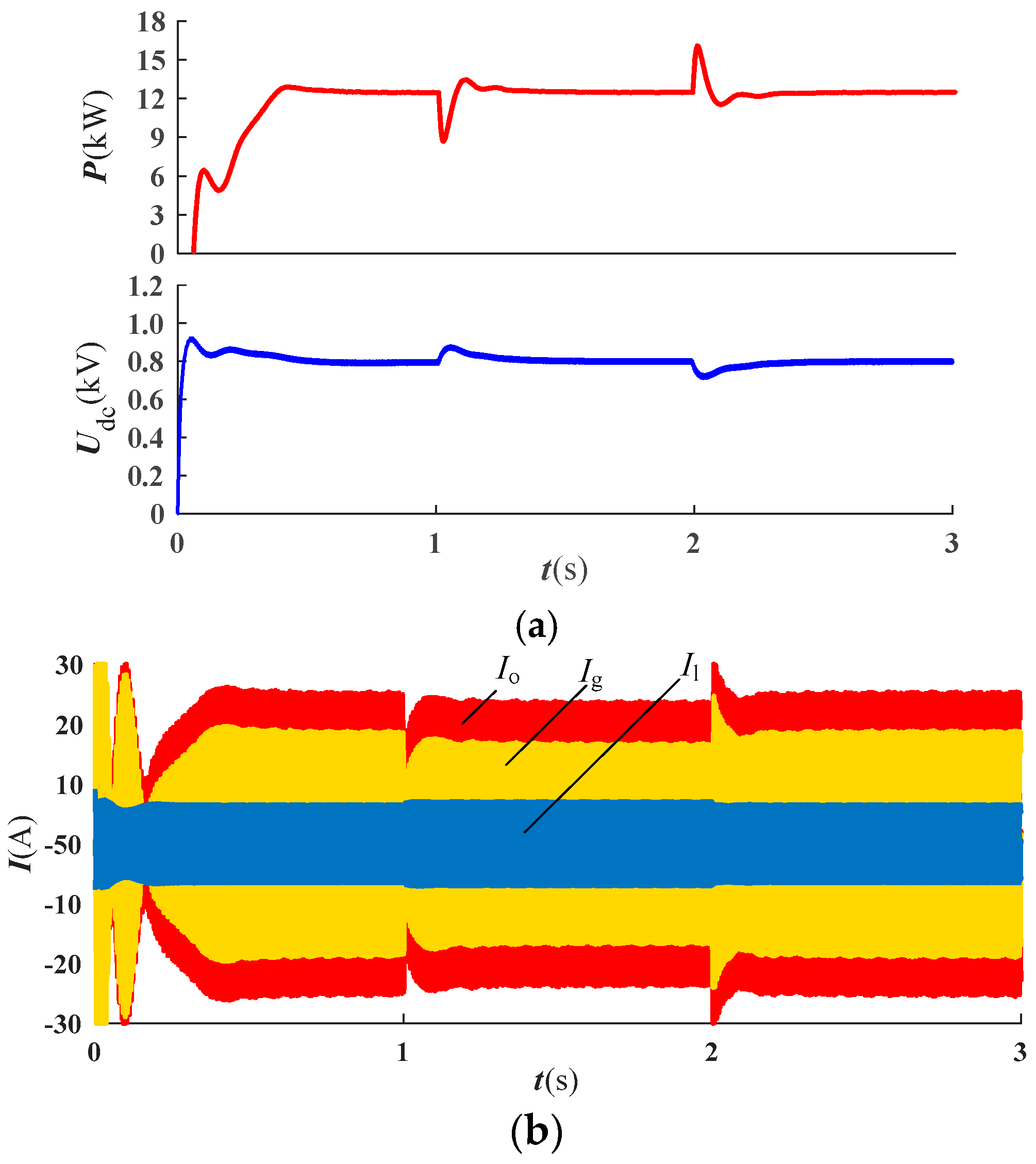
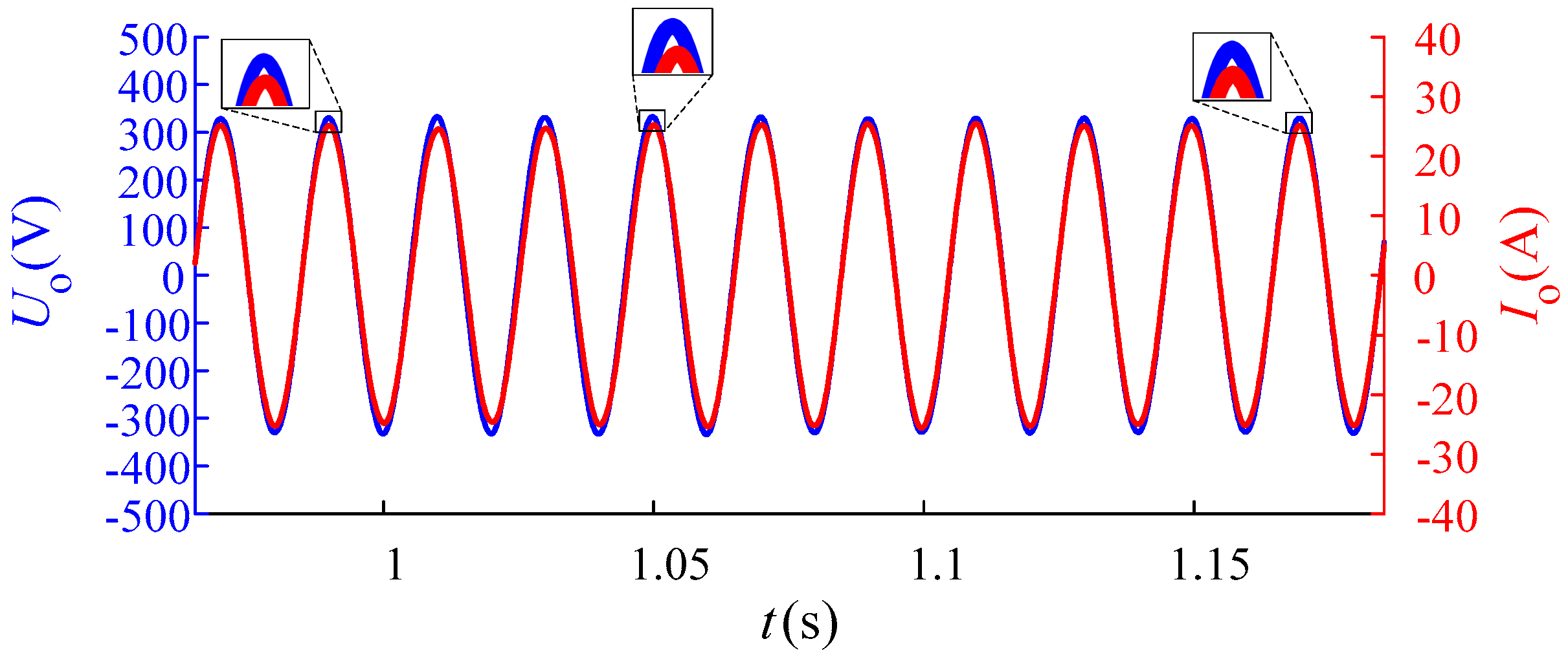
5.2. Verification of Direct Current (DC) Voltage Loop

In order to verify the effect of the DC voltage loop, the grid voltage amplitude was changed, then the inverter output power and DC voltage are observed. Considering that the laboratory environment is better than the actual operation environment, step tests in the laboratory environment should adopt stricter conditions (larger voltage changes). So we set the voltage step change value to 15%. The grid voltage amplitude is suddenly increased by 57 V ( 380 × 15 % ) at the first second, and the rated value is restored at the second second. The inverter’s operating results are shown in Figure 9.
In Figure 9a, the DC bus voltage and inverter output active power quickly return to their initial values (800 V and 12.5 kW) after the grid fluctuates. During the transient process, the trend of U dc and P is negatively correlated, which is consistent with Equation (14). In Figure 9b, when the grid voltage fluctuates, I o and I g change rapidly with P and then quickly restore their rated value. It can be seen that the DC voltage loop not only stabilizes the DC bus voltage but also eliminates the influence of grid voltage disturbance on the output of the inverter, which enhances the stable operation of the system.

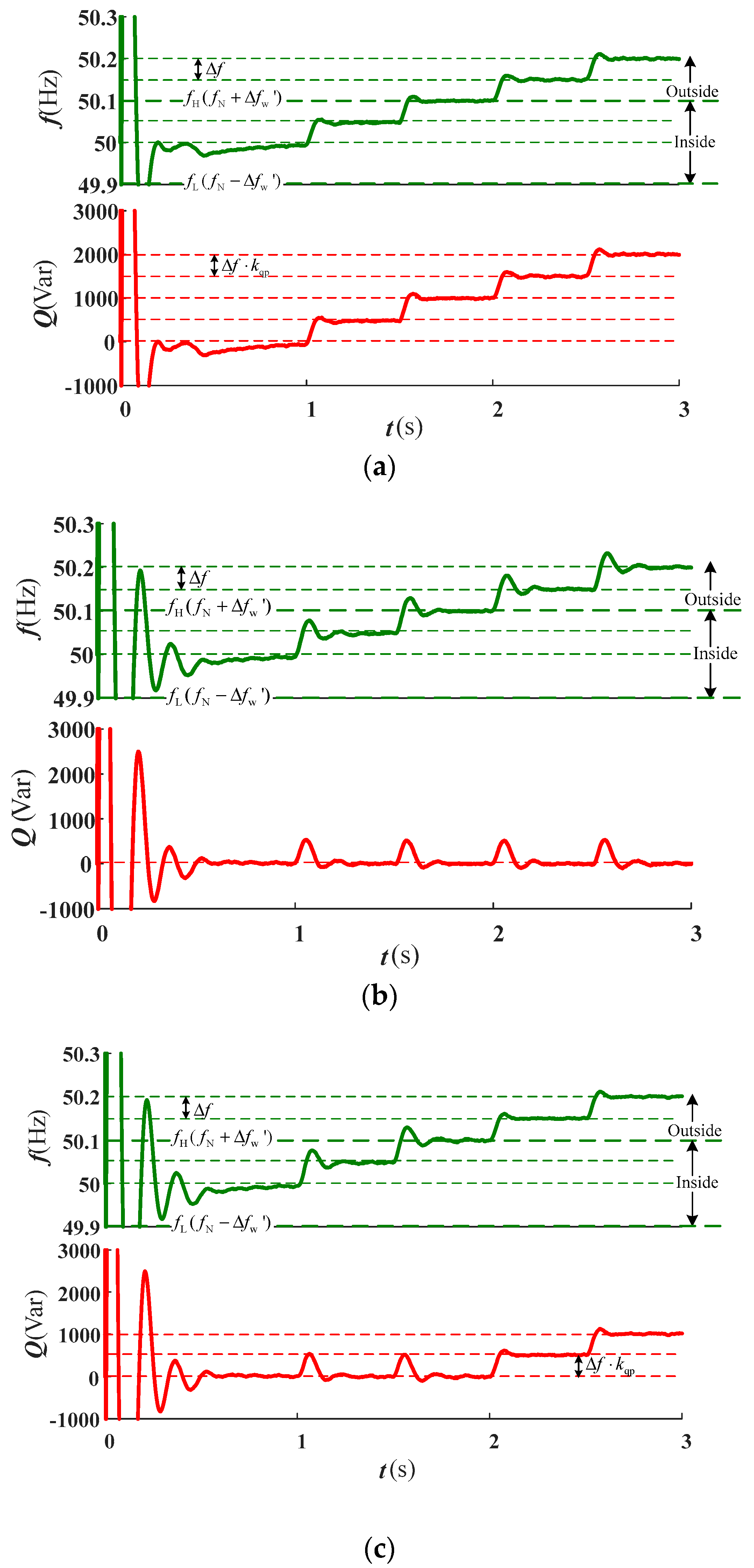
5.3. Verification of Failure Zone Characteristics

In this section, the failure zone feature of the system is verified. In order to fully present the role of the failure zone, the verification of this part is divided into two parts. Firstly, the characteristics in the failure zone are observed. Then, the characteristics in the failure zone and outside the failure zone are compared with each other.
In order to observe the characteristics in the failure zone, the frequency variation is set at 0.07 Hz which is lower than Δ f w (0.1 Hz). If the reactive power output from the inverter is still stable at the rated value (0 Var), it means that the inverter has a failure zone characteristic. The grid is set to operate at an initial value of 50 Hz, which is increased to 50.07 Hz at the first second. The inverter operation results are shown in Figure 10, where the reactive power can be reflected by the phase relationship between voltage and current.
In initial state, the inverter maintains a unity power factor output according to the rated reactive power Q r . Therefore, the phase of output voltage and current are the same before 1 the first second. The change in the grid frequency at the first second causes a slight change in the reactive power at the inverter output, which can be indicated by the phase difference between U o and I o . The system is in the failure zone for the reason of 0.07 A0 Hz < Δ f w , thus the reactive power output by the inverter is adjusted to 0 within 0.2 s. The above results show that the failure zone characteristics of the synchronous generator governor can be simulated.
Then, the characteristics inside the failure zone and outside the failure zone were observed together. At the same time, in order to obviously show the differences between the proposed control method, PQ (constant active power and reactive power) control method and droop control method. The results of these three control schemes are presented so that they can be compared with each other. In the following experiment, the grid frequency is increased by Δ f (0.05 Hz) from 50 Hz in the first second, the 1.5th second, the 2nd second and the 2.5th second respectively. By comparing with droop control and PQ control, the failure zone characteristics of the proposed control scheme can be observed clearly (see Figure 11).
From the Figure 11, it can be seen that the inverter operates in rated condition in all cases in the initial state. For the droop control in Figure 11a, the grid frequency rose to 50.05 Hz at the first second. The slight frequency fluctuation is lower than Δ f w (0.1 Hz), but the droop controlled inverter still sensitively changes the output power from 0 Var to 500 Var. Note that 500 Var is equal to Δ f k qp . Then, at the 1.5th second, the 2nd second and the 2.5th second, the inverter outputs 500 Var reactive power for every 0.05 Hz increase in frequency. It is clear that droop control makes the inverter participate in frequency regulation, but the output power also changes when the frequency changes slightly.
For the PQ control in Figure 11b, the grid frequency rose to 50.05 Hz at the first second. The frequency fluctuation is lower than Δ f w (0.1 Hz), so the inverter output reactive power recovers the rated value 0 Var after a brief transient process, which is consistent with expectation. The same situation occurs after the second frequency change. Then, at the 2nd second, the grid frequency increased to 50.15 Hz. At this time, the frequency changes so much that it exceeds the failure zone. However, reactive power output from the inverter still remains unchanged even if the grid frequency continues to rise to 50.2 Hz. As shown in the Figure 11b, PQ control achieves the constant power output of the inverter, but the inverter loses the frequency regulation capability when the frequency deviation is large. In the scenario of low renewable energy penetration, it is acceptable to operate the inverter with a PQ source because there are sufficient synchronous generators that can perform the task of frequency regulation. However, with the popularization of renewable energy, inverters are expected to actively participate in the frequency regulation of the power system in order to share the burden of synchronous generators.
For the proposed novel control in Figure 11c, when the frequency does not change beyond the failure zone, the inverter operates as a PQ source. Once the change of frequency exceeds the failure zone (after 2nd second), the inverter will participate in frequency regulation by adjusting the output power. The proposed novel control scheme enables the system to simulate the failure zone characteristics of a conventional synchronous generator governor. The inverter has a failure zone | ± Δ f w |   Hz , which allows the inverter to make intelligent choices between resisting grid fluctuations and participating in grid frequency regulation based on the actual situations. Note that the failure zone is symmetrical about the rated frequency. The simulation in this paper takes the upper threshold of the failure zone as an example. With the same effect, the lower threshold of the failure zone will not be described in detail herein.

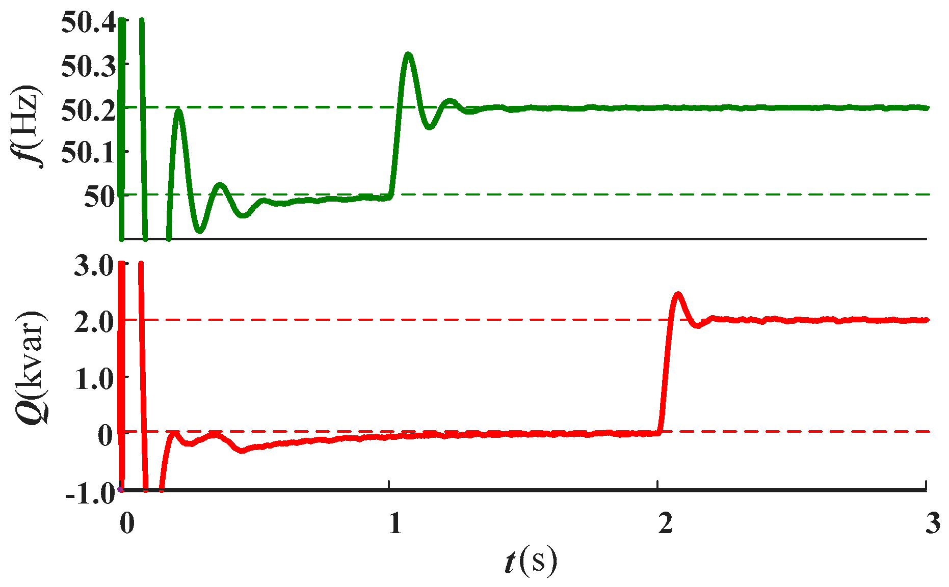
5.4. Verification of the Dispatching Interface

Dispatching interfaces should have a higher priority than failure zone, which means that when the dispatch does not require the inverter to participate in a frequency regulation, the inverter always outputs a constant power even if the frequency is outside the failure zone. In order to verify the effectiveness of the dispatching interface, the inverter is initially operated in the rated state. Then a sudden big frequency increase of 0.2 Hz is set at the first second. The frequency regulation instruction dispatched by the dispatching interface is received at the 2nd second. The response of the inverter is shown in Figure 12.
It can be seen from Figure 12 that the renewable energy based inverter still operates at constant power even though the frequency increment exceeds the failure zone threshold before the 2nd second. At exactly the time when the frequency regulation instruction is sent to the inverter, the inverter immediately participates in primary frequency regulation. The above results verify the effectiveness of the dispatching interface and the schedulability of the renewable energy inverter.

6. Conclusions

With the increase of renewable energy penetration rate, how to make renewable energy based inverters simulate and replace conventional synchronous generator to undertake frequency regulation tasks is a problem that needs to be solved urgently. The conclusions of this article are as follows:
(1)
In this paper, based on the characteristics of speed governor system of the conventional generator, the traditional static frequency characteristics are corrected. Then a novel two-stage grid-connected photovoltaic inverter voltage-type control method with the characteristics of the governor’s failure zone is proposed. The dynamic balance between resisting fluctuations, participation in frequency regulation and dispatching response is achieved.
(2)
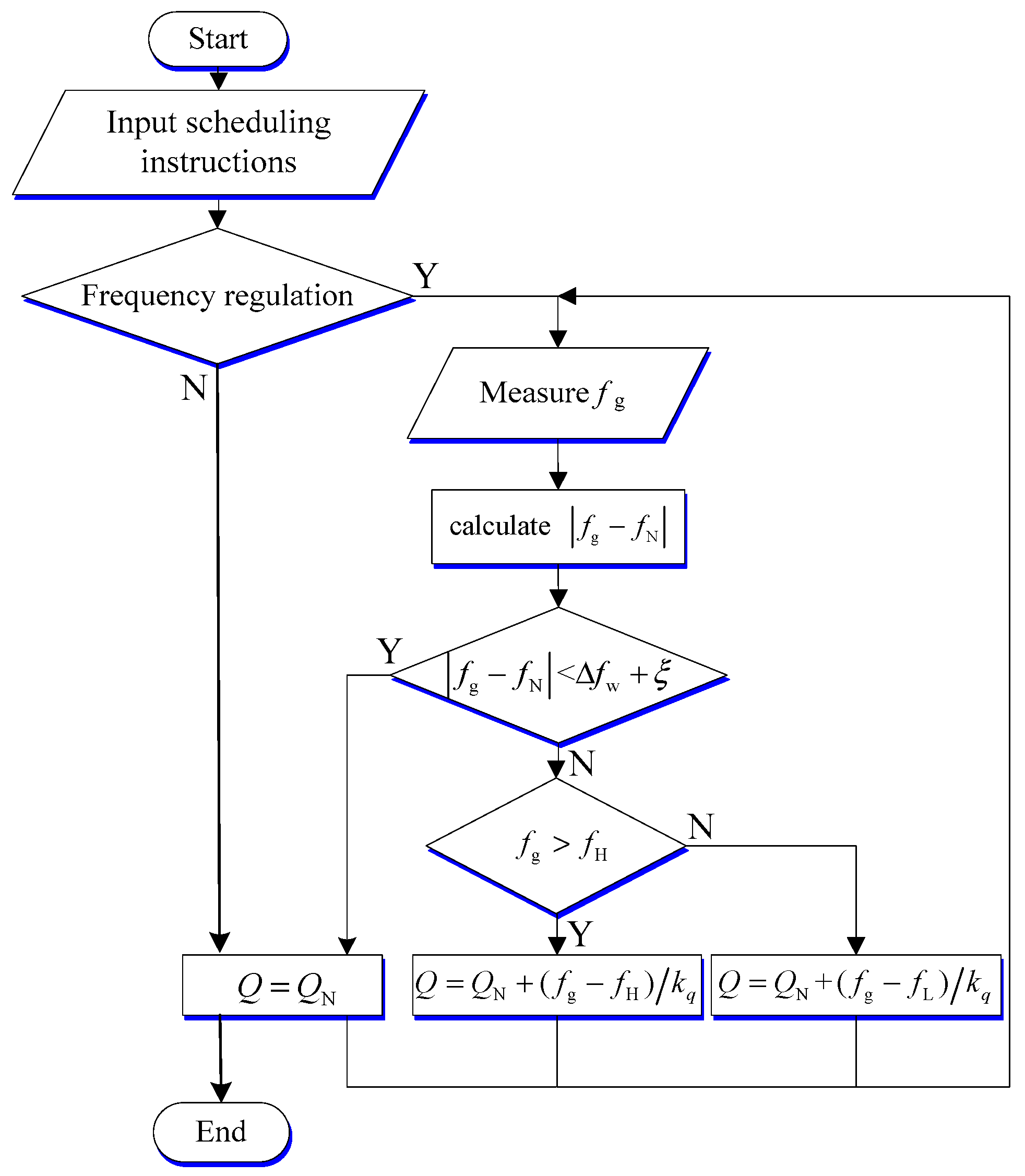
Through the improvement of the droop control and the design of the power enabling link, the inverter possesses the failure zone characteristics of the synchronous generator. For small frequency fluctuations inside the failure zone, the inverter maintains a constant output. If the frequency fluctuation exceeds the failure zone, the inverter participates in grid frequency regulation according to the droop relationship.
(3)
Whether or not the inverter participates in frequency regulation should be controllable rather than completely autonomous, especially when there are many renewable energy sources. The design of the dispatch interface ensures the schedulability of the inverter.
(4)
The frequency regulation delay of renewable energy ξ was introduced to improve inverters’ adaptability to renewable energy penetration rate. Therefore, the proposed control scheme can achieve the best operating state in an environment with any renewable energy penetration rate through flexible parameter settings.
(5)
A DC voltage loop was designed, which has two roles. On the one hand, it stabilizes the DC bus voltage to achieve operations without energy storage. On the other hand, it ensures that the system is not affected by the grid and delivers the maximum power to the grid stably.
(6)
The selection of failure zone thresholds for renewable energy based inverters and coordinated control of multi-inverters can be researched in the future.

Author Contributions

X.Y. and B.Z. conceived the method; X.Z. and B.Z. designed the method; X.Z. and M.W. achieved the method; X.Z., Z.J. and J.J. analyzed the results; X.Z. and T.L. wrote the paper.

Funding

This paper was supported by National Key R&D Program of China (2016YFB0900400), National Science Fundings of Hebei (E2018502134), Scientific Research Program of Hebei University (Z2017132). In addition, this article was funded by 2018 science and technology project of Liaoning Power Grid Corporation “Research on power grid reactive voltage optimization strategy and evaluation index considering the characteristics of source and load fluctuations”.

Conflicts of Interest

The authors declare no conflict of interest.

Appendix A

Table A1. Main parameters of the system.
Meaning and SymbolsValue
Maximum power of photovoltaic array Ppvmax12.5 kW
The capacitor on the output side of the photovoltaic array Cpv 1000   μ F
Capacitor at DC (direct current) bus Cdc 2000   μ F
Filter inductor Lf2.2 mH
Filter capacitor Cf 800   μ F
The amplitude of the inverter’s rated output voltage Ur 220 2 V
The reference value of inverter’s DC voltage Udcr800 V
Inverter rated frequency fr50 Hz
Inverter rated output reactive power Qr0 var
The proportional gain of the reactive power loop kqp0.0001
The integral gain of the reactive power loop kqi0.0015
The proportional gain of the DC voltage loop kup0.5
The integral gain of the DC voltage loop kui3
The proportional gain of the voltage loop koup1.4
The integral gain of the voltage loop koui3.2
The proportional gain of the current loop koip1
The integral gain of the current loop koii0
The   maximum   frequency   hysteresis   of   the   governor   Δ f w 0.033 Hz
The   upper   limit   frequency   of   failure   zone   f H 50.033 Hz
The   lower   limit   frequency   of   failure   zone   f L 49.967 Hz
The frequency regulation delay of the inverter ξ 0.067 Hz
The   failure   zone   threshold   of   inverter   Δ f w 0.1 Hz

Appendix B

Figure A1. Overall control scheme of inverter (detailed).
Energies 11 01865 g0a1

References

  1. Bose, B.K. Global energy scenario and impact of power electronics in 21st century. IEEE Trans. Ind. Electron. 2013, 60, 2638–2651. [Google Scholar] [CrossRef]
  2. Zhou, Y.; Gong, D.C.; Huang, B.; Peters, B.A. The impacts of carbon tariff on green supply chain design. IEEE Trans. Autom. Sci. Eng. 2017, 14, 1542–1555. [Google Scholar] [CrossRef]
  3. Wang, Y.; Lin, X.; Pedram, M. A near-optimal model-based control algorithm for households equipped with residential photovoltaic power generation and energy storage systems. IEEE Trans. Sustain. Energy 2016, 7, 77–86. [Google Scholar] [CrossRef]
  4. Cho, Y.W.; Cha, W.J.; Kwon, J.M.; Kwon, B.H. Improved single phase transformerless inverter with high power density and high efficiency for grid-connected photovoltaic systems. IET Renew. Power Gener. 2016, 10, 166–174. [Google Scholar] [CrossRef]
  5. Rocabert, J.; Luna, A.; Blaabjerg, F.; Rodríguez, P. Control of power converters in ac microgrids. IEEE Trans. Power Electron. 2012, 27, 4734–4749. [Google Scholar] [CrossRef]
  6. Strasser, T.; Andrén, F.; Kathan, J.; Kathan, J.; Kathan, J.; Siano, P.; Siano, P.; Zhabelova, G.; Zhabelova, G.; Vrba, P.; Mařík, V. A review of architectures and concepts for intelligence in future electric energy systems. IEEE Trans. Ind. Electron. 2015, 62, 2424–2438. [Google Scholar] [CrossRef]
  7. Daher, S.; Schmid, J.; Antunes, F.L.M. Multilevel inverter topologies for stand-alone PV systems. IEEE Trans. Ind. Electron. 2008, 55, 2703–2712. [Google Scholar] [CrossRef]
  8. Kjaer, S.B.; Pedersen, J.K.; Blaabjerg, F. A review of single phase grid connected inverters for photovoltaic modules. IEEE Trans. Ind. Appl. 2005, 41, 1292–1306. [Google Scholar] [CrossRef]
  9. Kim, K.A.; Seo, G.S.; Cho, B.H.; Krein, P.T. Photovoltaic hot-spot detection for solar panel substrings using AC parameter characterization. IEEE Trans. Power Electron. 2016, 31, 1121–1130. [Google Scholar] [CrossRef]
  10. Debnath, D.; Chatterjee, K. Two-stage solar photovoltaic-based standalone scheme having battery as energy storage element for rural deployment. IEEE Trans. Ind. Electron. 2015, 62, 4148–4157. [Google Scholar] [CrossRef]
  11. Alajmi, B.N.; Ahmed, K.H.; Finney, S.J.; Williams, B.W. A maximum power point tracking technique for partially shaded photovoltaic systems in microgrids. IEEE Trans. Ind. Electron. 2013, 62, 1596–1606. [Google Scholar] [CrossRef]
  12. Choi, W.Y. Three-level single-ended primary-inductor converter for photovoltaic power conditioning systems. Sol. Energy 2016, 62, 43–50. [Google Scholar] [CrossRef]
  13. Kanaan, H.; Caron, M.; Al-Haddad, K. Design and implementation of a two-stage grid-connected high efficiency power load emulator. IEEE Trans. Power Electron. 2014, 29, 3997–4006. [Google Scholar] [CrossRef]
  14. Blaabjerg, F.; Teodorescu, R.; Liserre, M.; Timbus, A.V. Overview of control and grid synchronization for distributed power generation. IEEE Trans. Ind. Electron. 2006, 53, 1398–1409. [Google Scholar] [CrossRef]
  15. Liu, J.; Cheng, S.; Shen, A. Carrier-overlapping PWM-based hybrid current control strategy applied to two-stage grid-connected PV inverter. IET Power Electron. 2018, 11, 182–191. [Google Scholar] [CrossRef]
  16. Boukezata, B.; Gaubert, J.P.; Chaoui, A.; Hachemi, M. Predictive current control in multifunctional grid connected inverter interfaced by PV system. Sol. Energy 2016, 391, 130–141. [Google Scholar] [CrossRef]
  17. Vasquez, V.; Ortega, L.M.; Romero, D.; Ortega, R.; Carranza, O.; Rodriguez, J.J. Comparison of methods for controllers design of single phase inverter operating in island mode in a microgrid: Review. Renew. Sustain. Energy Rev. 2017, 76, 256–267. [Google Scholar] [CrossRef]
  18. Singh, M.; Khadkikar, V.; Chandra, A.; Varma, R.K. Grid interconnection of renewable energy sources at the distribution level with power quality improvement features. IEEE Trans. Power Deliv. 2011, 26, 307–315. [Google Scholar] [CrossRef]
  19. De Paiva, E.P.; Vieira, J.B.; De Freitas, L.C.; Farias, V.J.; Coelho, E.A.A. Small signal analysis applied to a single phase inverter connected to stiff AC system using a novel improved power controller. In Proceedings of the Twentieth Annual IEEE Applied Power Electronics Conference and Exposition, Austin, TX, USA, 6–10 March 2005. [Google Scholar]
  20. Avelar, H.J.; Parreira, W.A.; Vieira, J.B.; De Freitas, L.C.G.; Coelho, E.A.A. A State Equation Model of a Single-Phase Grid-Connected Inverter Using a Droop Control Scheme with Extra Phase Shift Control Action. IEEE Trans. Power Deliv. 2012, 59, 1527–1537. [Google Scholar] [CrossRef]
  21. Verma, V.; Khushalani-Solanki, S.; Solanki, J. Modeling and Criterion for Voltage Stability of Grid Connected Droop Controlled Inverter. In Proceedings of the 2017 North American Power Symposium (NAPS), Morgantown, WV, USA, 17–19 September 2017. [Google Scholar]
  22. Zhong, Q.C. Power electronics-enabled autonomous power systems: Architecture and technical routes. IEEE Trans. Ind. Electron. 2017, 64, 5907–5918. [Google Scholar] [CrossRef]
  23. Yan, X.W.; Zhang, X.Y.; Zhang, B.; Ma, Y.J.; Wu, M. Research on Distributed PV Storage Virtual Synchronous Generator System and Its Static Frequency Characteristic Analysis. Appl. Sci. 2018, 8, 532. [Google Scholar] [CrossRef]
  24. Vinayagam, A.; Alqumsan, A.A.; Swarna, K.S.V.; Khoo, S.Y.; Stojcevski, A. Intelligent control strategy in the islanded network of a solar PV microgrid. Electr. Power Syst. Res. 2018, 155, 93–103. [Google Scholar] [CrossRef]
  25. Grainger, J.J.; Stevenson, W.D.J. Power System Analysis; Stephen, E.H., Ed.; McGraw-Hill: Hightstown, NJ, USA, 1994; pp. 562–572. [Google Scholar]
  26. Viinamäki, J.; Kuperman, A.; Suntio, T. Grid-Forming-Mode Operation of Boost-Power-Stage Converter in PV-Generator-Interfacing Applications. Energies 2017, 10, 1033. [Google Scholar] [CrossRef]
  27. Moradi, M.H.; Reisi, A.R. A hybrid maximum power point tracking method for photovoltaic systems. Sol. Energy 2011, 85, 2965–2976. [Google Scholar] [CrossRef]
Figure 1. The grid-connected equivalent circuit of voltage-type inverter.
Energies 11 01865 g001
Figure 2. Failure zone of the generator governor.
Energies 11 01865 g002
Figure 3. Static frequency characteristics considering failure zone under low-voltage lines.
Energies 11 01865 g003
Figure 4. Logic flow chart of the system.
Energies 11 01865 g004
Figure 5. Regulation principle diagram in failure zone.
Energies 11 01865 g005
Figure 6. The principle of reactive power-frequency control.
Energies 11 01865 g006
Figure 7. Overall control scheme of inverter. PWM: pulse width modulation; PI: proportional–integral controller; MPPT: maximum power point tracking; SPWM: sinusoidal pulse width modulation; PV: photovoltaic; PLL: phase locked loop.
Energies 11 01865 g007
Figure 8. (a) Inverter output phase voltage amplitude and active power; (b) Source-Grid-Load current.
Energies 11 01865 g008
Figure 9. (a) DC bus voltage and inverter output active power; (b) Source-Grid-Load current.
Energies 11 01865 g009
Figure 10. Output voltage and current of inverter inside failure zone.
Energies 11 01865 g010
Figure 11. Comparison of droop control, PQ (constant active power and reactive power) control and proposed control (a) Droop control; (b) PQ control (c) Proposed novel control.
Energies 11 01865 g011
Figure 12. Dispatching response results of inverter.
Energies 11 01865 g012

