Assimilation of Optimal Sized Hybrid Photovoltaic-Biomass System by Dragonfly Algorithm with Grid

1
Department of Electrical and Instrumentation Engineering, Thapar Institute of Engineering and Technology, Patiala 147004, India
2
Optical Devices and Systems, CSIR-Central Scientific Instruments Organization, Sector 30-C, Chandigarh 160030, India
*
Author to whom correspondence should be addressed.
Energies 2018, 11(7), 1892; https://doi.org/10.3390/en11071892
Submission received: 5 June 2018
/
Revised: 3 July 2018
/
Accepted: 4 July 2018
/
Published: 20 July 2018
(This article belongs to the Section F: Electrical Engineering)
Abstract
:A growing interest in renewable energy resources has been observed for several years, due to their pollution-free nature, availability all over the world, and continuity. These facts make these energy resources attractive for many applications. In this work, the hybrid combination of a photovoltaic-biomass system is investigated as an energy source. This paper determines optimal sizing and cost reduction of grid-integrated renewable energy resources by using an intelligence optimization technique, the dragonfly algorithm. The efficiency of the proposed methodology is also compared with an existing technique, which uses the artificial bee colony (ABC) algorithm. The scope of this work is to reduce the annual total cost of power with a reduced number of solar panels. The monthly average solar radiation is used to compute the obtained power. The outcome of the proposed technique proves that the grid-connected system with an optimal number of components satisfactorily meets the needs of the village at a reduced price. The simulation results are carried out under the MATLAB environment. The comparison of results clearly demonstrates that the proposed system is much more efficient than the existing one.
1. Introduction
Renewable based hybrid energy systems have received great attention in recent years as they appear one of the clean sources of electricity generation. The major issues while designing of renewable based hybrid system are power management, reliability of the system and economic cost of energy [1]. The photovoltaic (PV) system can act as a standalone or grid-connected system. The system produces energy, which is then injected into the utility grid [2]. Biomass is a viable option for use as a renewable energy resource as it can be converted into electricity, biofuels, and heat. Electricity generated from gasification technology is very popular, especially in rural areas [3]. The distribution generation system can supply power to the load or building. PV systems are pollution free and are easily set up on the roof of the building [4].
Integration of renewable energy sources to the grid is a challenging job because of the intermittent nature of renewable energy sources [5]. The grid connection provides a back up to the hybrid system, which eliminates the need of batteries and diesel generators [6]. However, the electrification of rural areas requires a reliable power supply, low cost equipment, and the provision of adequate energy to the consumers. The power transmission issues in rural zones can be resolved by improving the power capacity and the installation of small-scale grid systems [7].
The perfect source of power is a sustainable source such as wind, rain or sunlight, which can be utilized in a hybrid or standalone manner. A remote area power supply, also known as a stand-alone power system, is used as an off-grid electricity system in locations that do not have electricity distribution [8,9]. In rural areas, electricity generation typically depends on photovoltaic and biomass systems, which are not directly coupled to the distributed power system [10]. The electricity drawn from stand-alone renewable resource systems can only partially meet the load demand. Therefore, PV systems are combined with battery banks in order to meet the load requirement [11,12].
The extent of the usability of a stand-alone system depends on specific factors, such as the power quality and system efficiency. Issues such as these have led to a focus on hybrid systems based on one or more renewable energy sources [13]. Grid-connected renewable energy sources can increase the sustainability, reliability and quality of the power system. Also, hybrid power systems are flexible and enduring [14].
Recently developed technologies have been used to connect renewable sources to the grid, which reduces cost, equipment size, and load matching. Hybrid energy systems are formed by a controller and energy storage system. In the summer, the grid connected solar system supplies the power to the load [15,16].
In remote areas, electrical power is frequently generated through biomass energy systems, which may be decomposed into a variety of materials, including wood and biogas. Biomass can also be obtained from various resources such as agricultural residues, and animal and human waste and biomass gasification and combustion processes produce power. [17]. The limitations of the stand-alone PV-biomass system include low efficiency, instability, and a high economic cost. However, the photovoltaic and biomass system can be enabled to improve the quality of power and energy efficiency [18]. Energy storage systems can be combined with hybrid power systems, in order to increase the load matching, furthermore, this can improve the frequency and voltage regulation [19].
The scope of the paper is to develop a mathematical model of a hybrid system (PV combined with biomass) connected to the grid, to minimize the number of panels and increase power generation. Even though fewer solar panels are used, power can be generated at a prescribed level.
The remaining paper is organized as follows: Section 2 presents the recent research in this area. The mathematical modelling of a grid-connected PV-biomass system and problem formulation is presented in Section 3 and Section 4, respectively. The proposed methodology is presented in Section 5, and the results and discussions are presented in Section 6. Finally, the conclusion is given in Section 7 followed by references used in the manuscript are recorded.
Problem formulation: The design of grid-connected PV-biomass system leads to an increased number of PV panels, increases the size of the biomass gasifier, and these increase the cost of the system.
Contribution of the work: The above problems can be rectified through the dragonfly (DF) algorithm; the performance of this is compared to the existing algorithms to show the effectiveness of the proposed system.
2. Related Works
Recent work related to the proposed model is discussed below.
Bhattacharjee et al. [20] developed a hybrid technology, generate power where, the maximum cost of the system was set as 0.143 $/kWh. The cost varies in accordance with the changes in the solar irradiance of the system. The grid electricity was generated in rice mills and the power utilization was about 90%.
A major concern in the literature is the optimal size of the grid-connected and the stand-alone PV system to supply electricity to a typical village. Behzadi et al. [21] analyzed the drawbacks of stand-alone renewable energy and proposed storage system, which was formed by PV panels and batteries along with an electrolyser/ a hydrogen tank. The secondary energy source of fuel cell was used as energy demands. The optimal sizing of the system was derived in this work using TRNSYS software. The TRNSYS data were used to achieve very accurate radiation and temperature. The power management strategies were found to be satisfactory.
In rural and remote locations, energy can be obtained from food processing waste, which is a form of biomass fuel for example, Garrido et al. [22] found that the cashew nut shell has great potential as a biomass fuel. They used the nut shells in a PV biomass system in a case study in Nampula, Mozambique. The results showed that this system had better levelised cost of energy than diesel generators.
Hurtado et al. [23] derived an optimization-based economic solution for distribution systems with hybridized renewable energy resources. The performance analysis was carried out with different kinds of renewable sources. In a proposed model, power generation was attained up to 98%, which totally satisfied the energy demand of the identified area. When energy demand increased, fossil fuel consumption and energy prices were increased. One of the main challenges of renewable energy was the cost of the technologies. Sharafi et al. [24]. designed and investigated a hybrid renewable energy system using generators and storage devices. In order to reduce the system cost, ε-constraint was applied and particle swarm optimization (PSO) was used to minimize the multi-objective optimization problem.
Singh and Kaushik [25] proposed a study methodology of village electrification with the help of energy resources. The two cases considered in this work were electrified only from renewable energy sources (RES) and electrification was carried out by grid-connected RES. They minimized the established objective function reported in [18]. They used the available modelling of solar PV cells and biomass gasifiers. Artificial bee colony (ABC) optimization was implemented to get the exact sizing and cost reduction. The proposed model was compared with the existing HOMER-based RES for sizing and cost reduction
Ortega et al. [26] presented guidelines for measuring and assessing the power quality (PQ) characteristics for photovoltaic (PV) systems at a site, which contain harmonics, flicker, unbalance, and slow voltage variations.
Bueno et al. [27] presented the modelling and analysis of transient and small-signal stability to represent transmission systems in scenarios of realistic loading and the deep penetration levels of PV.
Hernández et al. [28] suggested a model of a utility-scale photovoltaic unit (USPVU) combined with an embedded hybrid energy storage system (HESS) to enhance the performance of the system and made it fit to examine the stability of transmission systems.
Hernández et al. [29] suggested a general analytical technique (GAT) to show joint impact in an extended time frame. GAT is faster than the Monte-Carlo simulation and gave better accuracy. They showed the accuracy of the electric vehicle (EV) and PV interaction in RDSs.
Ruiz-Rodríguez et al. [30] proposed a method to feed biomass-fueled gas engines (BFGEs) with olive tree pruning residues that reduced the use of fossil fuel in vehicles and electricity generation. The capacity of electric vehicle (EV) charging stations was enhanced.
In this paper, the optimal sizing of the PV-biomass system is obtained by using the dragonfly algorithm. Also, the annualized capital cost is minimized. In addition to this, the reliability of power generation is compared with the existing system. The number of PV panels is reduced.
The research design is as follows:
- The research design of the proposed work models a grid-connected PV system with biomass for energy production.
- The dragonfly algorithm is introduced to reduce the cost, the number of PV panels, and size of the biomass gasifier system.
3. Mathematical Modelling
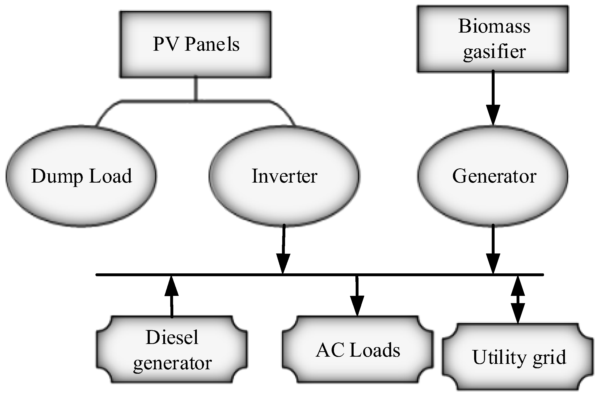
The performance of the PV-biomass system is analyzed using the mathematical modelling of the distributed power system. The proposed system consists of solar panels, gasifiers, a power inverter and utility grid. The schematic diagram of the hybrid PV-biomass energy system is shown in Figure 1, and each component is represented in the following section.
3.1. Solar Photovoltaic Panel
Equation (1) represents the output of a solar photovoltaic (PV) cell. The solar PV is a type of renewable energy resource, which fluctuates with weather conditions such as, rain, fog, clouds and snow. In Equation (1) indicates of the solar PV panel output power, denotes rated power of solar panel, is the PV panel loss factor, estimates the incident solar radiation within one hour, expresses standard incident radiation, means temperature coefficient of power, designates current temperature of a PV cell, and represents standard temperature under standard test condition (STC).
3.2. Biomass Gasifier
The producer gas is formed by conversion of solid fuel into gaseous combustible gas, which is given to the input of the combustion engine to produce electricity as expressed in Equation (2).
In Equation (2), the output of electricity is , the size (biomass) of gasifier system , depends on the capacity utilization factor (cuf).
The maximum size of the biomass gasifier system can be implemented in a particular area is expressed by Equation (3).
In Equation (3) the parameter of represents available total biomass, denotes biomass gasifier system efficiency, is the heating value of biomass, and is operating time of the biomass gasifier system.
3.3. Power Inverter
At the desired frequency, the inverter converts direct current into alternating current and serves it to the AC load. The rate of the inverter can be computed by Equation (4).
The amount of power generated by the solar panels is and is the inverter efficiency. The value of can be obtained by using Equation (5).
In Equation (5) denotes the solar panels in numbers and in Equation (6) indicates the maximum size of the inverter, which has been derived in terms of peak value of the load demand and maximum amount of power, which is delivered to the grid, expressed in kW.
3.4. Utility Grid
In this work the hybrid system is connected to the grid. The excess amount of power generated by the PV-biomass system is fed into the grid and the electricity demand not met by the system is imported from the grid. If it does not satisfy the load demand, the grid supplies power to the load.
The power fed into the grid and the power imported from the grid is represented by Equations (7) and (8).
In the above equations, the grid sale and grid purchase capacity can be defined in terms of and , respectively. is the load demand, is the total power generated in the PV system, and is the size of the biomass gasifier system.
The following are the limits for the utility grid:
- (i)
- The extent of power supplied to the grid does not exceed the maximum grid sale capacity, and
- (ii)
- The maximum power value furnished by the utility grid does not surpass the maximum extent of the grid purchase capacity.
4. Problem Formulation
The number of solar panels and size of the biomass gasifier system, with reduced cost of the components, was determined. The cost considered in the proposed work is the annual total cost. The annual total cost is the function of several costs, such as the annual cost of replacement, cost of maintenance, cost of fuel, and salvage value. The formula used for evaluating the objective of the proposed work is given by Equation (9).
where ATC represents the annual total cost, indicates the number of solar PV panels, denotes annual amount of solar photovoltaic panel (PV), is the total annual amount of biomass gasifier system, implies the rated biomass gasifier system, reflects rate of inverter, is the annualized total cost of the inverter, is the total capacity of electricity given to the grid, and illustrates the total capacity of electricity sales by the grid. Depending upon the above annual total cost, the levelised cost of energy (LCOE) of the proposed hybrid system connected to the grid was evaluated. The effective energy produced with a minimum amount of cost is defined as the levelised cost of energy. It is represented by Equation (10).
4.1. Constraints
The constraints of the objective function are given below.
4.1.1. Number of Solar Panels
The solar panels absorb the sunlight to generate electricity and it is supplied to the grid, where, the maximum number of solar PV panels can be represented like as .
4.1.2. Size of Gasifier
The biomass gasifier is the source of energy with a variety of fossil fuels, combustion and chemical composition characteristics. There are several types of biomass sources, including animal waste, sewage sludge, solid and agriculture residues. The biogas generator is used to produce electricity. The average rate of biogas supply is about 8 ton/day. In Equation (12) the maximum size of the biomass gasifier is represented as .
4.1.3. Grid Purchase Capacity
The purchase capacity is the maximum capacity of power that can be drawn from the grid at any time. The maximum amount of power is the amount that can be supplied by the grid and it never exceeds the grid sale capacity. The maximum grid purchase capacity is denoted by in Equation (13).
4.1.4. Grid Sale Capacity
The grid sale capacity is defined as the maximum power that can be obtained from the PV panel until solar irradiation is affected by weather patterns or environmental changes. Then, the system gets power from the grid during. The maximum grid sale capacity can be defined in terms of .
4.2. Cost Analysis with Biomass Gasifier
The cost analysis is an important factor, which is further extended to identify the amount of gasifier in the proposed system. The annual cost of the biomass system consists of the annualized capital cost (), annualized replacement cost (), maintenance cost (), fuel cost (), and salvage value () as given by Equation (15).
All the parameters utilized in Equation (15) are computed as below:
4.2.1. Annual Primitive Cost
The primitive cost allows for installation and purchase of components, and the cost of the solar photovoltaic panels, gasifier and power inverter. The cost computation is allied with the capacity recovery factor (crf) as expressed by Equation (16).
In Equation (16), ‘n’ is the rate of interest and ‘r’ states number of years. The annualized primitive cost of a biomass system can be computed by Equation (17).
where denotes the biomass gasifier system with the initial primitive cost.
4.2.2. Annual Replacement Value
The annual replacement value is calculated based on the costs that occurs during the lifetime of the project, which is reflected in the formula given by Equation (18).
represents the replacement cost of the component, and Y is the lifetime of the biomass component.
4.2.3. Maintenance Cost
This cost includes cost of labor, cost of repairs and additional payments to operate the biomass gasifier, which can be computed by Equation (19).
The parameter of represents the hourly working of the biomass gasifier system, and represents the maintenance rate of the biomass system in an hour. Lifetime is the number of operating hours, which can be represented by Equation (20).
From Equation (20), is the generator lifetime and spells out working time during one year.
4.2.4. Fuel Cost
Fuel cost depends on the price of the biomass , total energy generated by biomass , and rate of biomass consumption is mentioned in Equation (21).
4.2.5. Value of Salvage
The value of salvage is the estimated resale value of the biomass component at the end of its useful life, as expressed by Equation (22).
where is the replacement cost of the component, is the biomass gasifier system life span, and represents the remaining life period of the biomass gasifier system.
Total capacity of electricity purchased from the grid in a grid-connected system is expressed by Equation (23).
The locus of Equation (23) says that is grid supply power.
The cost of purchased electricity from the grid is given by Equation (24).
From Equation (24) is the unit cost of electricity.
The total cost of energy supplied to the grid is expressed by Equation (25).
is the power supplied to the grid.
The capacity of electricity sold to the grid is expressed by Equation (26).
where denotes the unit cost of electricity.
The expressions reflected in Equations (23)–(26) are the main economic concerns in a grid-connected system. It includes the cost of electricity shared between the grid and hybrid system.
5. Proposed Methodology
The proposed method is aimed at evaluating the ideal sizing of the hybrid connection to a photovoltaic biomass system, which is connected to the grid. In this paper the mathematical modelling of the hybrid system is provided. The objective of the project is to reduce the annualized total cost of the system with optimal number of components. The annualized cost reduction and optimal selection are evaluated through the evolutionary technique known as the dragonfly algorithm. From the annual total cost evaluation, the levelised cost of energy is calculated.
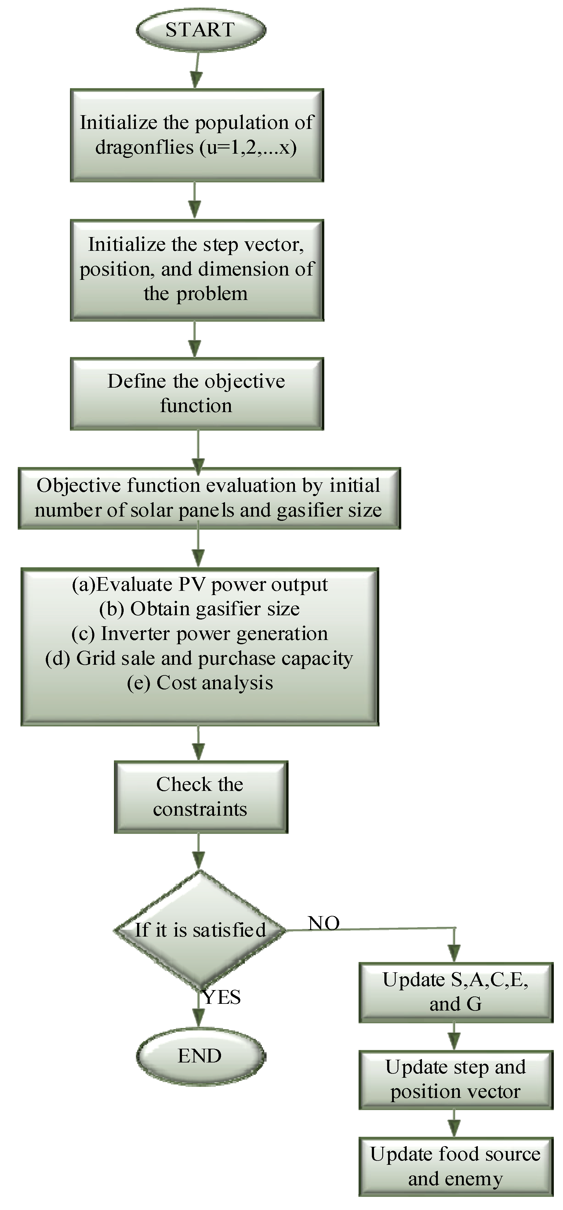
Proposed Algorithm
The dragonfly algorithm is developed from the inspiration of the swarming behavior of dragonflies [31]. The lifecycle of dragonflies involves two stages: nymph and adult. There are three golden rules included in the swarming activity of dragonflies. The objective function of the algorithm is to minimize the annual total cost. The rules behind the algorithm are explained below.
(a) Separation: Under the separation process static collision will be avoided from the individuals as noted by Equation (27).
In Equation (27) ‘’ represents the current position of the individual, ‘’ denotes position of neighboring individual, and ‘’ represents the number of neighboring individuals.
(b) Alignment: Alignment is the velocity matching individuals with other individuals. The calculation for alignment can be done by Equation (28).
In Equation (28) ‘’ denotes the velocity of the neighboring individual.
(c) Cohesion: The cohesion rule states the ability of individuals to move towards the center of the food as given by Equation (29).
In Equation (29), ‘q’ shows number of neighborhoods.
- (1)
- In an optimization procedure the first level is the initialization of parameters, including number of populations, maximum number of iterations, the bounds of the algorithm, and dimension of the work.
- (2)
- The objective function of the proposed work is defined in the second process. The parameters in the work to be optimized are the reduced annual total cost, gasifier size, and number of PV panels.
- (3)
- The initial population is generated within the constraints of the proposed methodology. The positions and step vectors are defined within the bounds. The grid-connected hybrid system is modelled by mathematical formula and done through the initial data.
- (4)
- Evaluate the objective function (OF) by using Equation (30).The objective interpretation starts with the fundamental guessing of the number of solar panels and gasifier size. The modelling computations are:
- (i)
- Evaluation of the power output of the photovoltaic panels using the Equation (1).
- (ii)
- Rating of biomass gasifier, electricity produced by the gasifier and inverter power generation is evaluated through Equations (2), (3), and (4), respectively.
- (iii)
- Capacity of the grid purchased and grid sale capacity by Equations (7) and (8), respectively.
- (5)
- The objective function evaluation is done according to the number of populations.
- (6)
- Constraints are checked with the objective function.
- (7)
- Repeat Steps 1 to 6.
- (8)
- Update the objectives by using the following expressions.
Update the step vector and position to find the swarming behavior of the dragonfly using Equation (31).
In Equation (31), S, A, and C are separation weight, alignment weight and cohesion weight respectively; ‘’ is the position [enemy] of individual ‘u’; ‘E’ is the enemy factor and ‘G’ is the inertia weight. The value of ‘’ can be calculated using Equation (32).
Then, the new position of each dragonfly is identified by using Equation (33).
The iterations of the dragonflies become continuous up to the optimum selection of the objective function.
6. Results
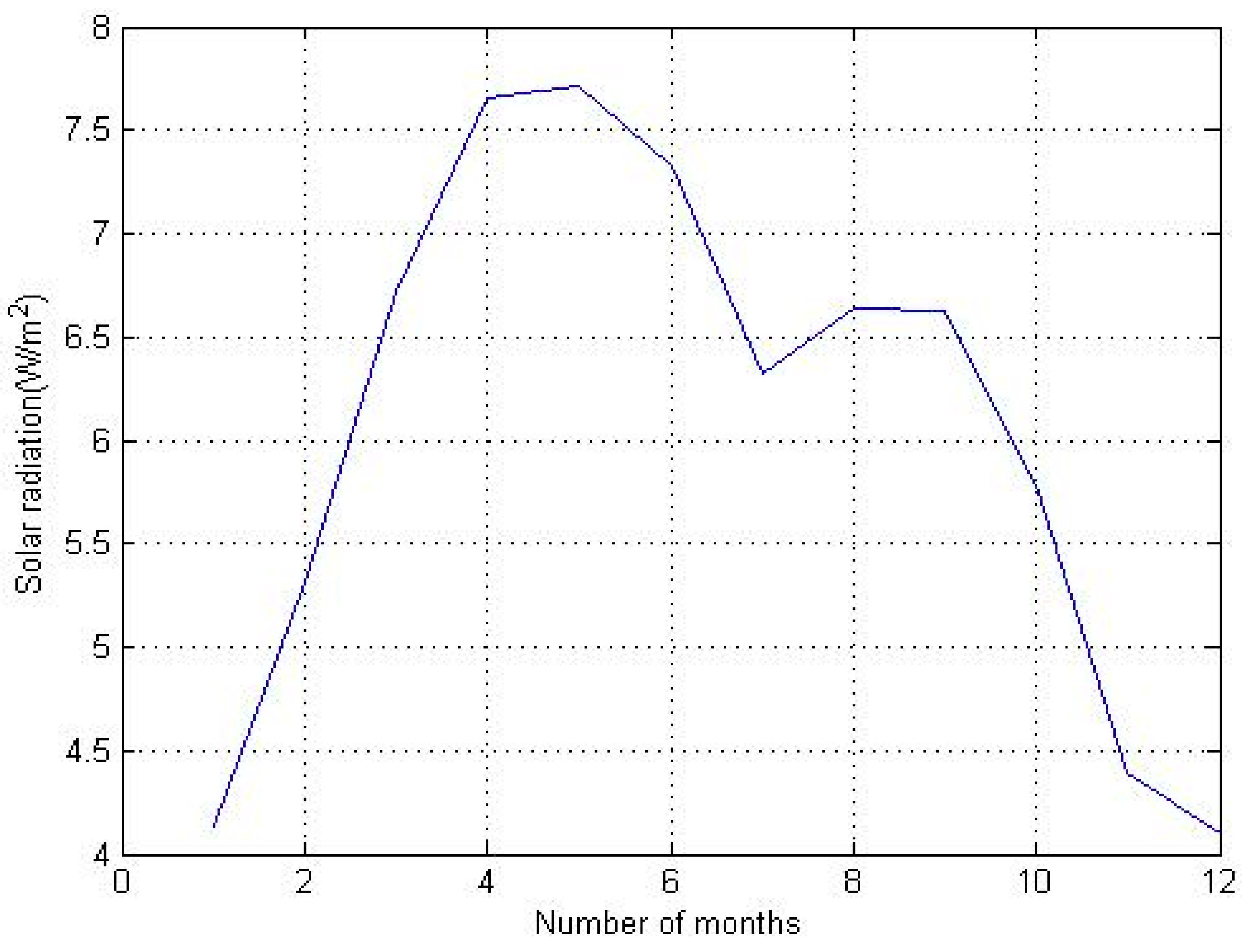
The entire simulation work was carried out in the working platform of MATLAB and version R2014a, with the system configuration of Windows 7 (operating system) with 4 GB RAM and operating speed 2.90 GHz. The monthly average solar radiations of the solar panels are taken from [32] for the village, Kaidupur located in Punjab State, India and it is given in Table 2. The village is known for its efficient use of biomass and solar energy. The median value of solar radiation is taken as 5.14 kWh/m2/day. The main sources of biomass in the village are wheat, paddy and pulses. The modelling took several factors such as interest rate (annual) = 6%; lifecycle = 20 years; maximum grid sale capacity = 50 kW; and grid purchase capacity = 5 kW into consideration.
Figure 3 shows that the average radiation from solar in the Kaidupur village for one year and Table 2 shows the monthly average solar radiation in the village. The above graph is plotted on the basis of Table 2.
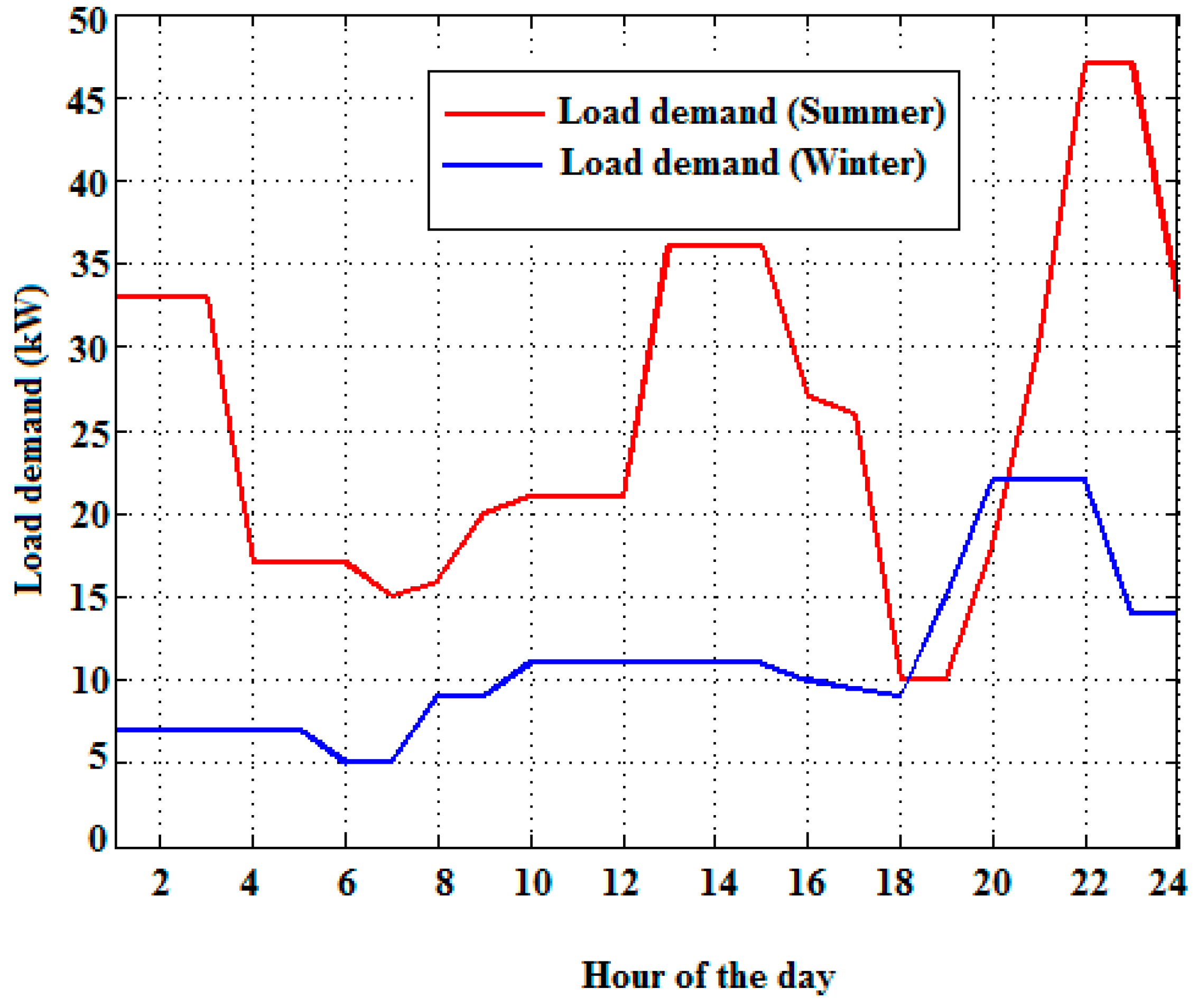
Figure 4 shows that the load profile during the summer and winter. During the winter season the load demand is low and in summer season the load demand is high.
The cost analysis of components for the optimal sizing of components in the grid-connected photovoltaic–biomass systems are provided in Table 3. From this detailed analysis, it can be seen that the dragonfly (DF) algorithm considerably reduces the annual total cost, and thus, the levelised cost of energy.
Table 3 shows that the comparison of proposed cost components with the existing algorithm, in which the initial, replacement, maintenance, fuel cost, the lifetime of PV panels, biomass gasifier system and the inverter is given. The proposed dragonfly algorithm yields better cost performance as well as lifetime. Compared to the ABC algorithm, the cost value of PV panels is reduced to 1152 $/kW and replacement cost is about 655$/kW $/kW, likewise, the cost value is reduced in the dragonfly algorithm compared to the existing ABC algorithm. Economically, the system cost is highly improved in the dragonfly algorithm compared to the artificial bee colony algorithm. The cost values are obtained by Equations (15)–(21).
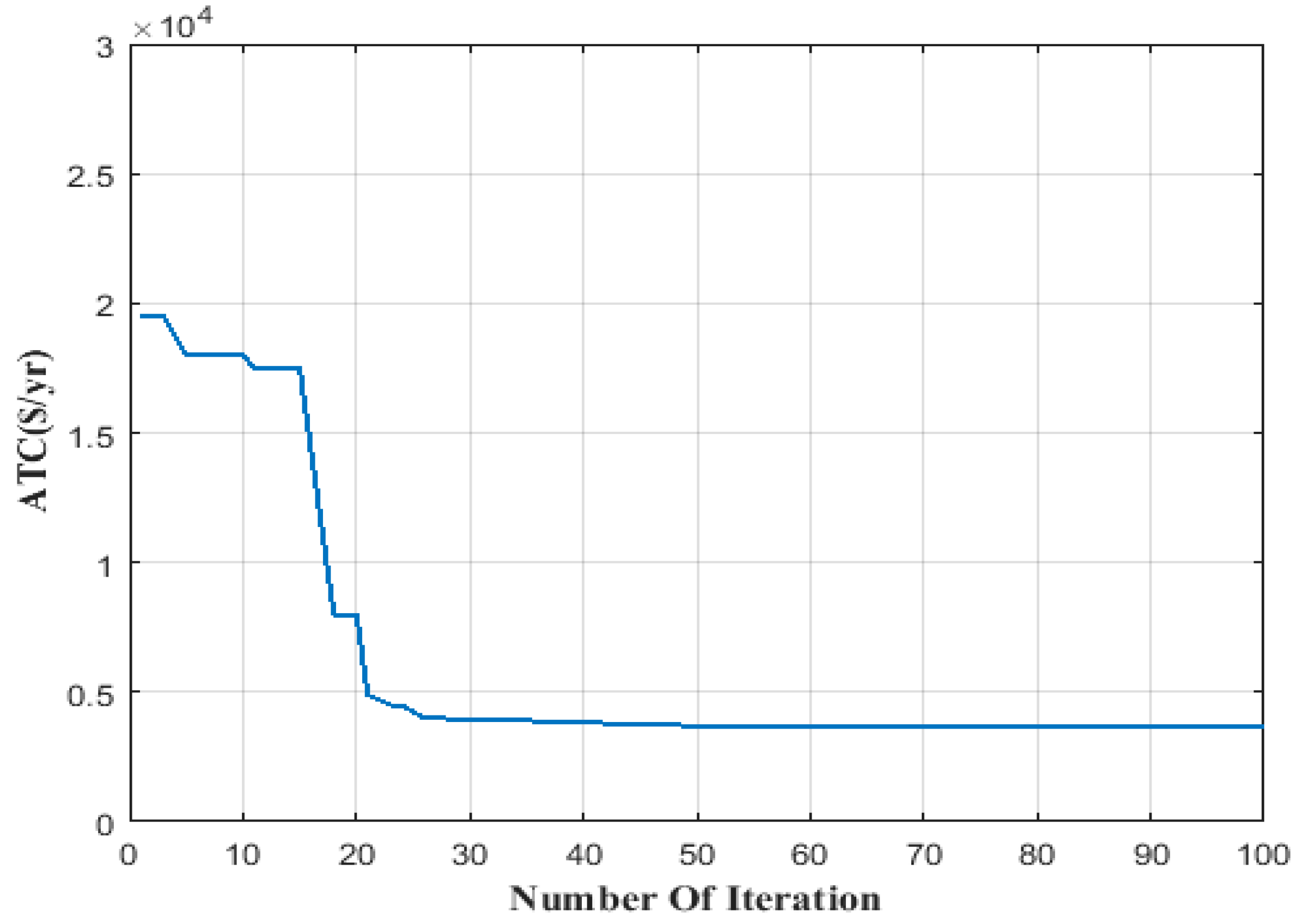
Figure 5 is the representation of total cost reduction by the proposed method plotted against number of iterations. The replacement cost for PV panel by ABC is 1200 $/kW and by dragonfly it is 655 $/kW. Also, for biomass gasifier and inverter costs by ABC algorithm it is 1834 $/kW and 127 $/kW, respectively. The reduction for biomass and inverter is 819 $/kW and 69 $/kW respectively. The annual total cost is obtained through Equation (9).
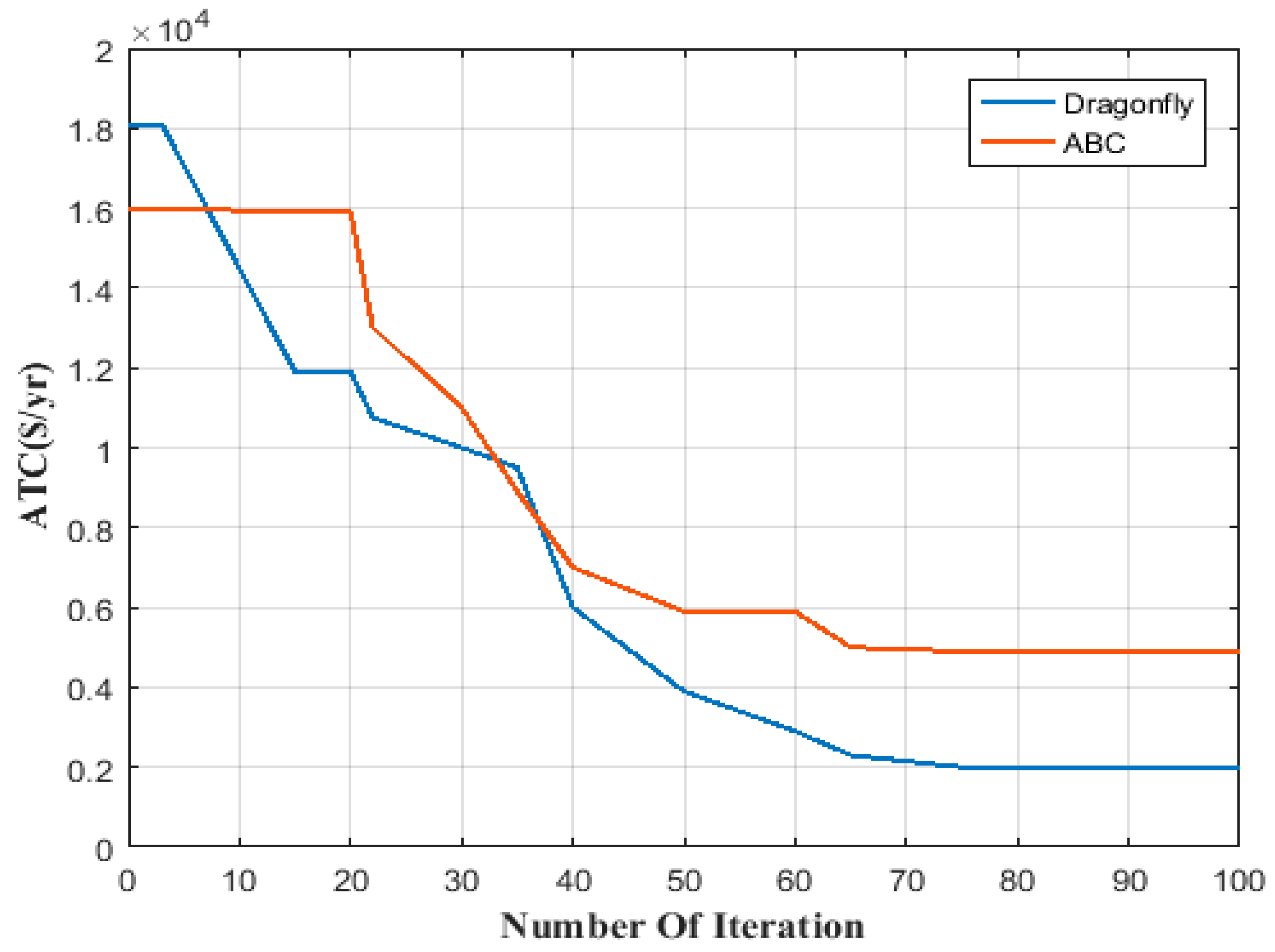
The efficiency of the proposed method in terms of cost reduction is compared with the ABC algorithm and shown in Figure 6. The reduced cost obtained by the proposed dragonfly algorithm is 19,318 $/yr. This amount is obtained with a reduced number of solar panels (71) and a biomass gasifier of 42 kW.
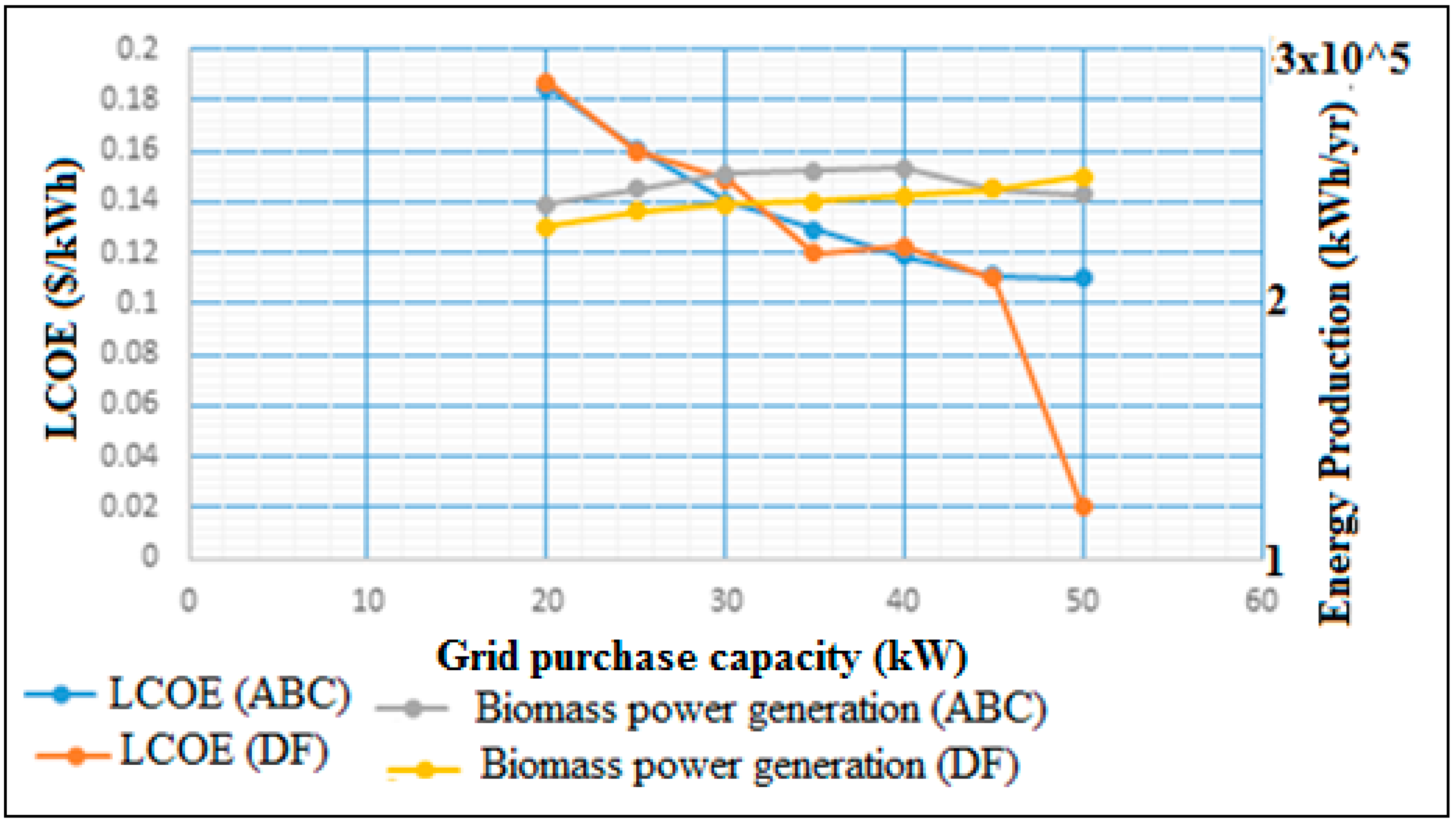
Figure 7 presents the power generation by biomass and solar panels with the minimized levelised cost of energy. The blue line indicates the grid sale capacity which is inversely proportional to the levelised cost of energy. If the grid sale capacity decreases, then the levelised cost of energy increases, and vice versa.
Figure 8 explains the behavior of LCOE and biomass. The maximum grid sale capacity is plotted on the X label and levelised cost of energy is plotted on the Y label. If the energy production of biomass is low, then the LCOE value gets increased and it has been found in [25].
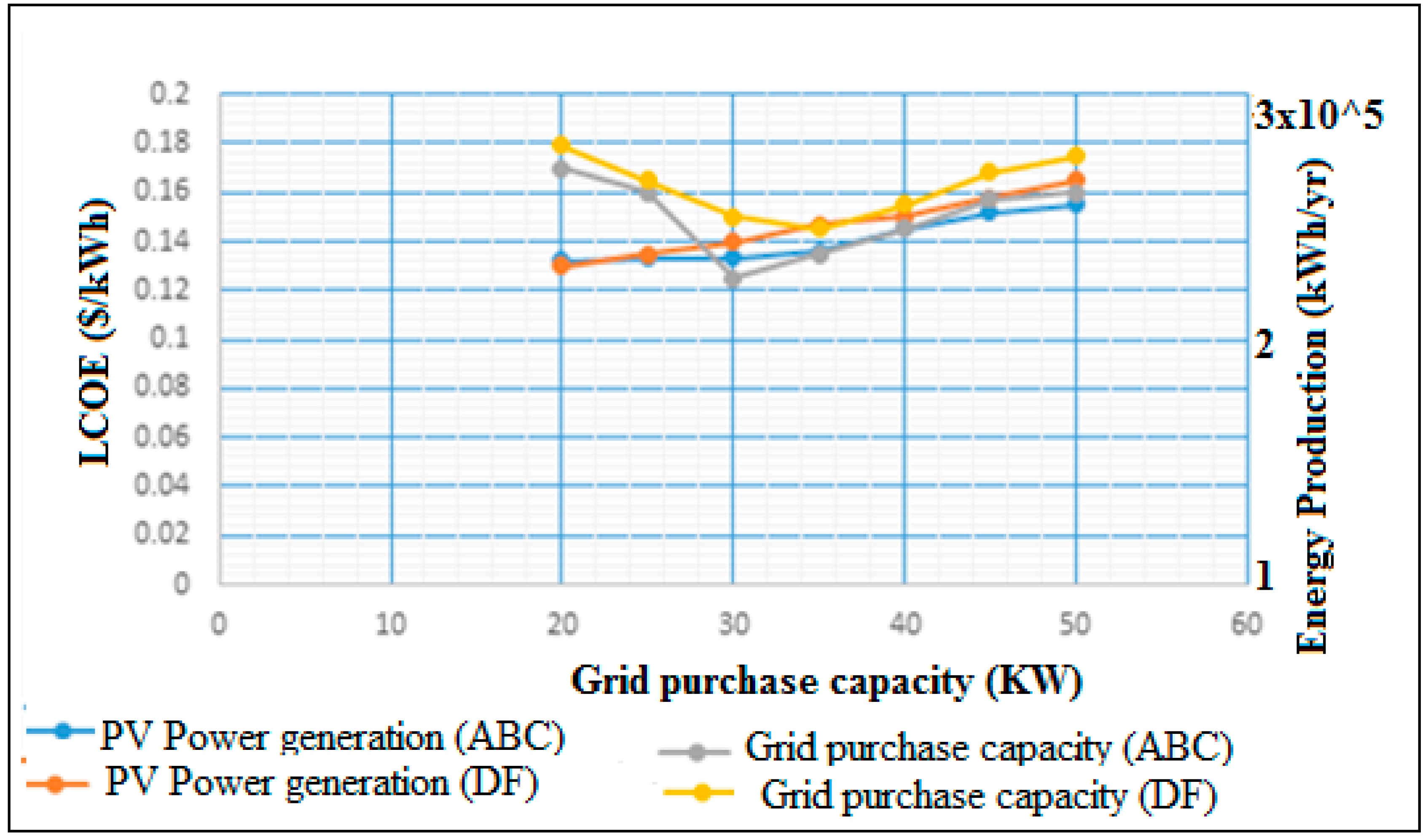
Figure 9 shows that the total energy production of photovoltaic panels is high when compared with the existing method (ABC), and that the grid sale capacity value also increases. The grid sale capacity is increased, when the LCOE value is small as possible. Figure 7 and Figure 8 show the grid sale capacity, and the energy production is also given. The sale capacity is the maximum amount of power the system can sell to the utility grid. The purchase capacity is the maximum amount of power the system can purchase from the utility grid.
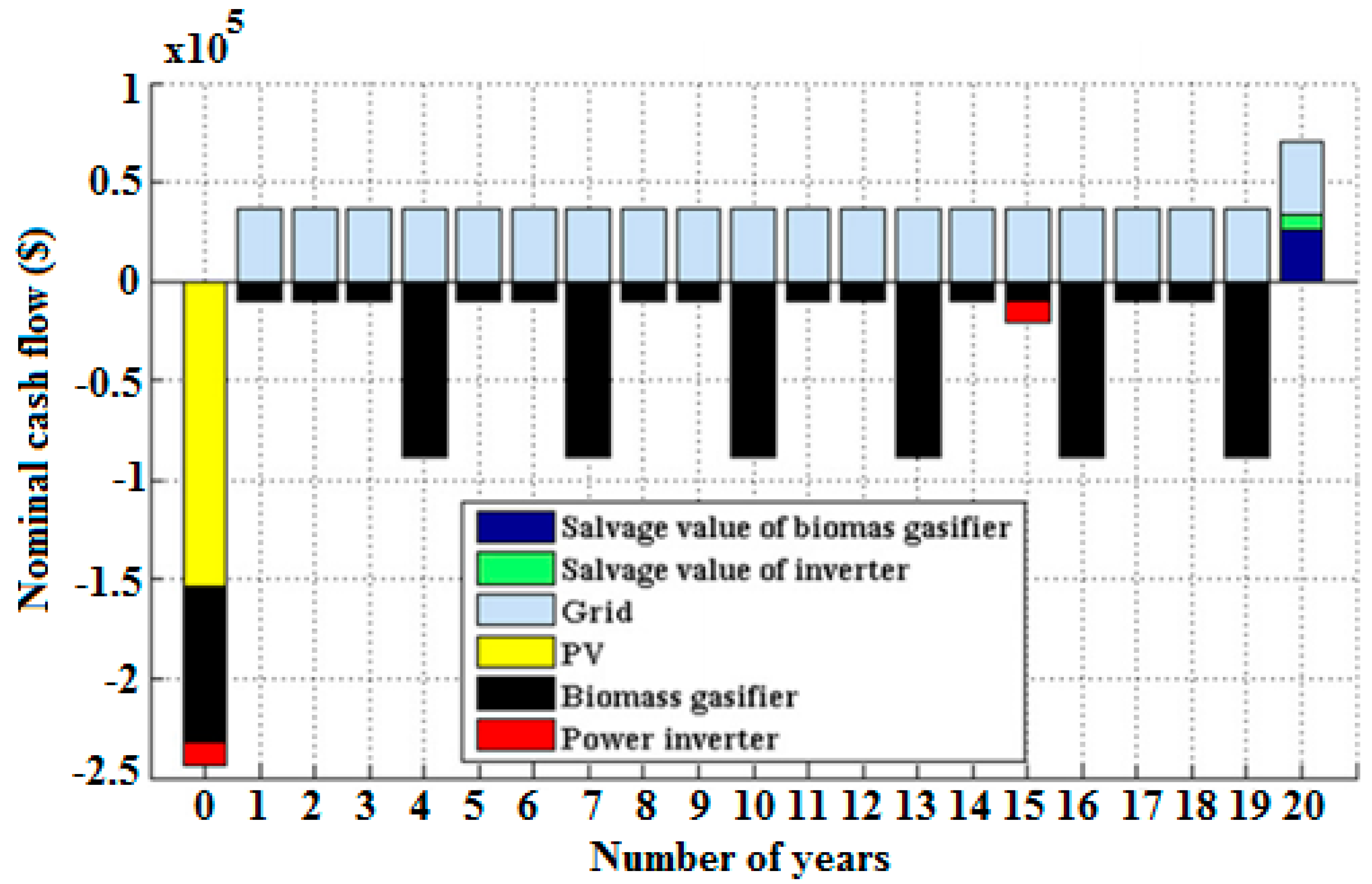
The cash flow of the grid, salvage value, biomass gasifier system, PV, and power inverter, which vary with the years are shown in Figure 9.
The comparison of the outcomes obtained by the DF algorithm (proposed method) with that of obtained by the ABC algorithm [25] are shown in Table 4.
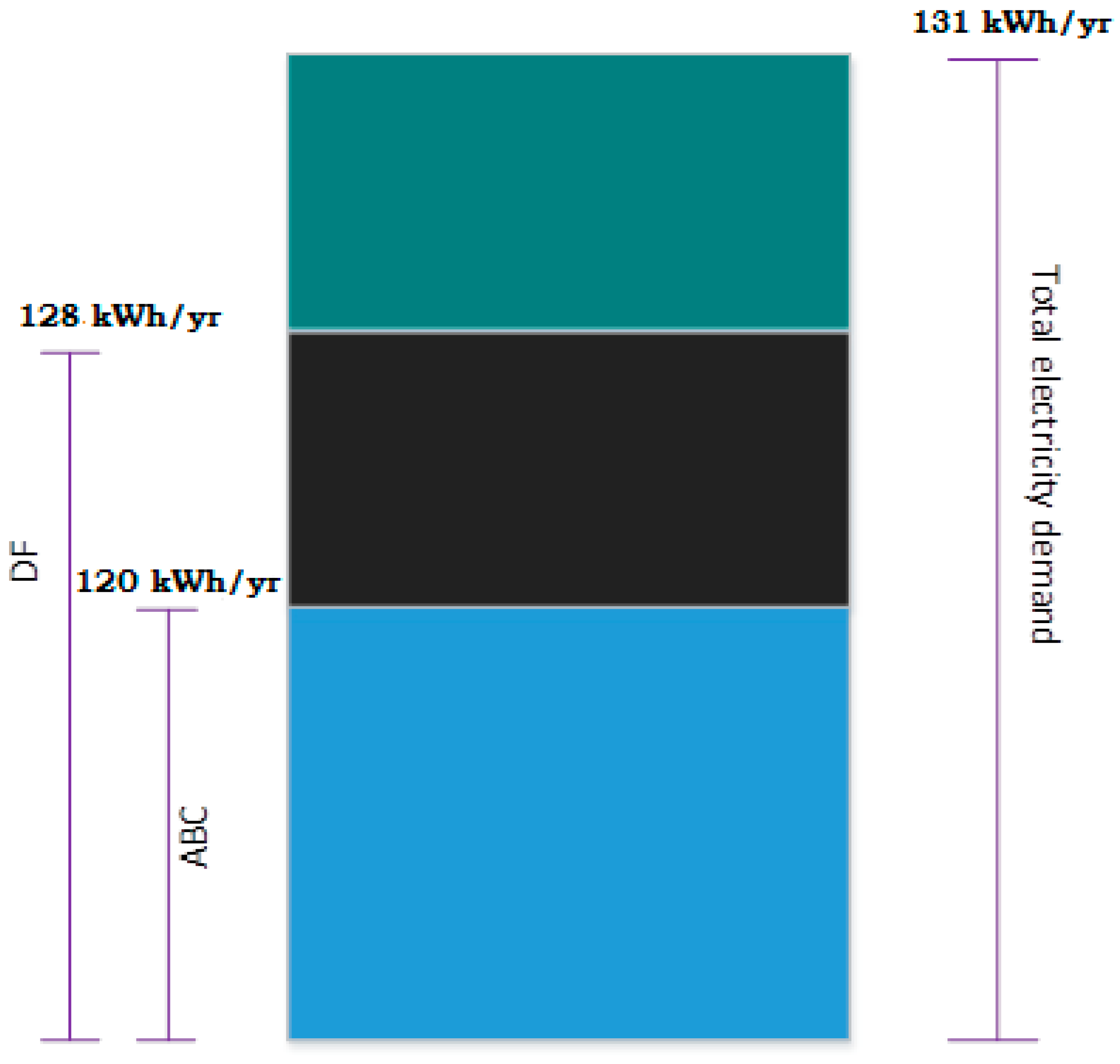
In this paper the electricity demand is approximately 131 kWh/yr and this is shown in Figure 9.
Figure 10 shows that the reliability of power generation compared with existing system. By using the proposed DF, 128 kWh/yr will be provided to almost satisfy the demand of 131 kWh/yr, which is more reliable than that of the ABC.
The reliability of the proposed work, load profile, monthly average solar radiation, nominal cash flow, comparison results, annual total cost, and grid purchase, sale capacity demonstrate the effectiveness of the proposed system.
The comparative results of the hybrid (photovoltaic-biomass) grid connection is analyzed in Table 4. These include:
- The biomass size is reduced in terms of the total usage of biomass and calorific value.
- The total usage of solar PV panels is reduced due to the high power generated in the single solar panel. So, the cost can be reduced.
- The overall values are very important in cost analysis, then, the additional parameters of the rate and cost of the inverter are reduced so that the whole cost is reduced annually.
- Due to the reduction of annual total cost and the load satisfaction, the levelised cost of energy is also minimized.
The advantages of proposed system are:
- ♦
- Fast convergence while using the dragonfly algorithm.
- ♦
- The annualized total cost is reduced.
- ♦
- It is highly efficient.
- ♦
- The high power generation with a reduced number of PV panels.
7. Conclusions
Electrification of rural areas is a significant factor in the progress of a developing country like India. The installation and maintenance of the power grid is a very difficult and uneconomical issue. The electricity in the rural areas is provided with the help of renewable energy resources. In this work, grid-connected hybrid photovoltaic--biomass energy systems were investigated. The economic issues related to this proposed hybrid combination were optimized with the help of the dragonfly algorithm. The algorithm not only reduces the annual total cost but also assists the proper selection of component size with a limited number of PV panels. The theoretical limitations were considered for MATLAB simulation. The result obtained by the proposed methodology was compared with the existing ABC algorithm and it was proved that the selected optimization method significantly reduced the cost with an optimum number of components. The load profile, annualized cost, the grid sale and the purchase capacity are defined in the graphs. Thus, the obtained results clearly show that a hybrid system with grid connection significantly reduces the cost of electric power supply for villages in developing countries. Comparisons of the results obtained by the dragonfly algorithm (proposed method) with the ABC algorithm [25] showed that the results obtained by the proposed method are better than those obtained by the ABC algorithm. This work can be applied to other resources, and update research methods where cost estimation is detected through algorithms.
Author Contributions
The problem formulation, code development, implementation of code and manuscript preparation had been carried out jointly by the first author and second author.
Funding
The funding was provided by CSIR-Central Scientific Instruments Organization; Sector 30-C, Chandigarh-160030.
Acknowledgments
Authors are thankful to the Director of Thapar Institute of Engineering and Technology, Patiala, Punjab, India and Director, CSIR-Central Scientific Instruments Organization; Sector 30-C, Chandigarh-160030, India for providing the environment to carry out this work.
Conflicts of Interest
The authors declare no conflict of interest.
Nomenclature
| Solar PV panel output power | |
| Rated power of solar panel | |
| PV panel loss factor | |
| Incident solar radiation | |
| Temperature coefficient of power | |
| Current temperature of a PV cell | |
| Temperature under standard test condition | |
| Annual output of electricity | |
| Rate (biomass) of gasifier system | |
| Maximum size of the biomass gasifier system | |
| Available total biomass | |
| Biomass gasifier system efficiency | |
| Heating value of biomass | |
| Operating time of the biomass gasifier system | |
| Power generated by the solar panels | |
| Solar panels in numbers | |
| maximum size of the inverter | |
| Grid sale capacity | |
| Grid purchase capacity | |
| Load Demand | |
| Total power generation in PV system | |
| Rated biomass gasifier system | |
| Number of solar PV panels | |
| Annual amount of solar photovoltaic panel (PV | |
| Annual amount of biomass gasifier system | |
| Annualized total cost of the inverter | |
| Total amount of electricity given to the grid | |
| Total amount of electricity sale by the grid. | |
| Maximum number of solar PV panels | |
| Maximum size of biomass gasifier | |
| Maximum grid purchase capacity | |
| Annualized capital cost | |
| Annualized replacement cost | |
| Maintenance cost | |
| Fuel cost | |
| Salvage value | |
| Unit cost of electricity | |
| Biomass gasifier system with initial primitive cost |
References
- Carrasco, J.M.; Franquelo, L.G.; Bialasiewicz, J.T.; Galván, E.; PortilloGuisado, R.C.; Prats, M.M.; León, J.I.; Moreno-Alfonso, N. Power-electronic systems for the grid integration of renewable energy sources: A survey. IEEE Trans. Ind. Electron. 2006, 53, 1002–1016. [Google Scholar] [CrossRef]
- Martins, D.C.; Demonti, R. Grid connected PV system using two energy processing stages. In Proceedings of the Conference Record of the Twenty-Ninth IEEE Photovoltaic Specialists Conference, New Orleans, LA, USA, 19–24 May 2002; pp. 1649–1652. [Google Scholar]
- Singh, S.; Singh, M.; Kaushik, S.C. Feasibility study of an islanded microgrid in rural area consisting of PV, wind, biomass and battery energy storage system. Energy Convers. Manag. 2016, 128, 178–190. [Google Scholar] [CrossRef]
- Zahedi, A. Solar photovoltaic (PV) energy; latest developments in the building integrated and hybrid PV systems. Renew. Energy 2006, 31, 711–718. [Google Scholar] [CrossRef]
- Nema, P.; Nema, R.K.; Rangnekar, S. A current and future state of art development of hybrid energy system using wind and PV-solar: A review. Renew. Sustain. Energy Rev. 2009, 13, 2096–2103. [Google Scholar] [CrossRef]
- Kanase-Patil, A.B.; Saini, R.P.; Sharma, M.P. Integrated renewable energy systems for off grid rural electrification of remote area. Renew. Energy 2010, 35, 1342–1349. [Google Scholar] [CrossRef]
- Heine, P.; Lehtonen, M. Voltage sag distributions caused by power system faults. IEEE Trans. Power Syst. 2007, 18, 1367–1373. [Google Scholar] [CrossRef]
- Weitemeyer, S.; Kleinhans, D.; Vogt, T.; Agert, C. Integration of Renewable Energy Sources in future power systems: The role of storage. Renew. Energy 2015, 75, 14–20. [Google Scholar] [CrossRef] [Green Version]
- Ismail, M.S.; Moghavvemi, M.; Mahlia, T.M.I.; Muttaqi, K.M.; Moghavvemi, S. Effective utilization of excess energy in standalone hybrid renewable energy systems for improving comfort ability and reducing cost of energy: A review and analysis. Renew. Sustain. Energy Rev. 2015, 42, 726–734. [Google Scholar] [CrossRef] [Green Version]
- Chauhan, A.; Saini, R.P. Renewable energy based off-grid rural electrification in Uttarakhand state of India: Technology options, modelling method, barriers and recommendations. Renew. Sustain. Energy Rev. 2015, 51, 662–681. [Google Scholar] [CrossRef]
- Delavaripour, H.; Dehkordi, B.M. Reliability evaluation of a standalone wind-photovoltaic/battery energy system based on realistic model of battery. J. Renew. Sustain. Energy 2015, 27, 013107. [Google Scholar] [CrossRef]
- Dalton, G.J.; Lockington, D.A.; Baldock, T.E. Feasibility analysis of stand-alone renewable energy supply options for a large hotel. Renew. Energy 2008, 33, 1475–1490. [Google Scholar] [CrossRef]
- Nehrir, M.H.; Wang, C.; Strunz, K.; Aki, H.; Ramakumar, R.; Bing, J.; Miao, Z.; Salameh, Z. A review of hybrid renewable/alternative energy systems for electric power generation: Configurations, control, and applications. IEEE Trans. Sustain. Energy 2008, 2, 392–403. [Google Scholar] [CrossRef]
- Lopes, J.A.P.; Soares, F.J.; Almeida, P.M.R. Integration of electric vehicles in the electric power system. Proc. IEEE 2011, 99, 168–183. [Google Scholar] [CrossRef]
- Salnikov, A.; Levchenko, R.; Sudakov, O. Integrated grid environment for massive distributed computing in neuroscience. In Proceedings of the 6th IEEE International Conference on Intelligent Data Acquisition and Advanced Computing Systems, Prague, Czech Republic, 15–17 September 2011; Volume 1, pp. 198–202. [Google Scholar] [CrossRef]
- Bajpai, P.; Dash, V. Hybrid renewable energy systems for power generation in stand-alone applications: A review. Renew. Sustain. Energy Rev. 2012, 16, 2926–2939. [Google Scholar] [CrossRef]
- Dhass, A.D.; Santhanam, H. Cost effective hybrid energy system employing solar-wind-biomass resources for rural electrification. Int. J. Renew. Energy Res. 2013, 3, 222–229. [Google Scholar]
- Yang, H.; Zhou, W.; Lu, L.; Fang, Z. Optimal sizing method for stand-alone hybrid solar—Wind system with LPSP technology by using genetic algorithm. Sol. Energy 2008, 82, 354–367. [Google Scholar] [CrossRef]
- Balamurugan, P.; Ashok, S.; Jose, T.L. Optimal operation of biomass/wind/PV hybrid energy system for rural areas. Int. J. Green Energy 2009, 6, 104–116. [Google Scholar] [CrossRef]
- Bhattacharjee, S.; Dey, A. Techno-economic performance evaluation of grid integrated PV-biomass hybrid power generation for rice mill. Sustain. Energy Technol. Assess. 2014, 1, 6–16. [Google Scholar] [CrossRef]
- Behzadi, M.S.; Niasati, M. Comparative performance analysis of a hybrid PV/FC/battery stand-alone system using different power management strategies and sizing approaches. Int. J. Hydrogen Energy 2015, 40, 538548. [Google Scholar] [CrossRef]
- Garrido, H.; Vendeirinho, V.; Brito, M.C. Feasibility of KUDURA hybrid generation system in Mozambique: Sensitivity study of the small-scale PV-biomass and PV-diesel power generation hybrid system. Renew. Energy 2016, 1, 47–57. [Google Scholar] [CrossRef]
- Hurtado, E.; Peñalvo-López, E.; Pérez-Navarro, A.; Vargas, C.; Alfonso, D. Optimization of a hybrid renewable system for high feasibility application in non-connected zones. Appl. Energy 2015, 155, 308–314. [Google Scholar] [CrossRef] [Green Version]
- Sharafi, M.; ELMekkawy, T.Y. Multi-objective optimal design of hybrid renewable energy systems using PSO-simulation based approach. Renew. Energy 2014, 68, 67–79. [Google Scholar] [CrossRef]
- Singh, S.; Kaushik, S.C. Optimal sizing of grid integrated hybrid PV-biomass energy system using artificial bee colony algorithm. IET Renew. Power Gener. 2016, 10, 642–650. [Google Scholar] [CrossRef]
- Ortega, M.J.; Hernández, J.C.; García, O.G. Measurement and assessment of power quality characteristics for photovoltaic systems: Harmonics, flicker, unbalance, and slow voltage variations. Electr. Power Syst. Res. 2013, 96, 23–35. [Google Scholar] [CrossRef]
- Bueno, P.G.; Hernández, J.C.; Ruiz-Rodriguez, F.J. Stability assessment for transmission systems with large utility-scale photovoltaic units. IET Renew. Power Gener. 2016, 10, 584–597. [Google Scholar] [CrossRef]
- Hernández, J.C.; Bueno, P.G.; Sanchez-Sutil, F. Enhanced utility-scale photovoltaic units with frequency support functions and dynamic grid support for transmission systems. IET Renew. Power Gener. 2017, 11, 361–372. [Google Scholar] [CrossRef]
- Hernández, J.C.; Ruiz-Rodriguez, F.J.; Jurado, F. Modelling and assessment of the combined technical impact of electric vehicles and photovoltaic generation in radial distribution systems. Energy 2017, 141, 316–332. [Google Scholar] [CrossRef]
- Ruiz-Rodríguez, F.J.; Hernández, J.C.; Jurado, F. Probabilistic Load-Flow Analysis of Biomass-Fuelled Gas Engines with Electrical Vehicles in Distribution Systems. Energies 2017, 10, 1536. [Google Scholar] [CrossRef]
- Mirjalili, S. Dragonfly algorithm: A new meta-heuristic optimization technique for solving single-objective, discrete, and multi-objective problems. Neural Comput. Appl. 2016, 27, 1053–1073. [Google Scholar] [CrossRef]
- Mishra, R.; Singh, S. Sustainable energy plan for a village in Punjab for self-energy generation. Int. J. Renew. Energy Res. 2013, 3, 640–646. [Google Scholar]
Figure 1.
Schematic diagram of hybrid PV-biomass energy system.

Figure 2.
Flow chart for the proposed algorithm.

Figure 3.
Average solar radiation versus months.

Figure 4.
The load profile of summer and winter.

Figure 5.
ATC vs Iteration number for DF.

Figure 6.
Comparison of ATC vs number of iterations of ABC and DF algorithms.

Figure 7.
Comparison result of biomass power generation and levelised cost of energy (LCOE) with ABC.
Figure 7.
Comparison result of biomass power generation and levelised cost of energy (LCOE) with ABC.

Figure 8.
Comparison of PV power generation and grid sale capacity with ABC.

Figure 9.
Nominal cash flow of the system.

Figure 10.
Reliability.


Table 1.
Parameter Initialization.
| Number of iterations | 100 |
| Number of population | 5 |
| Dimension of the problem | 8 |
| Upper Bound | 30 |
Table 2.
Monthly average solar radiation.
| Month | Solar Radiation, kwh/m2/day |
|---|---|
| January | 4.134 |
| February | 5.314 |
| March | 6.719 |
| April | 7.660 |
| May | 8.708 |
| June | 5.325 |
| July | 4.990 |
| August | 4.687 |
| September | 4.626 |
| October | 3.784 |
| November | 2.946 |
| December | 2.100 |
Table 3.
Cost of components by dragonfly algorithm (proposed method) and the artificial bee colony (ABC) algorithm [25].
Table 3.
Cost of components by dragonfly algorithm (proposed method) and the artificial bee colony (ABC) algorithm [25].
| Components | Initial Cost /kW,$ | Replacement Cost/kW,$ | Maintenance Cost/kW | Fuel Cost | Lifetime | |||||
|---|---|---|---|---|---|---|---|---|---|---|
| Method | ABC | DF | ABC | DF | ABC | DF | ABC | DF | ABC | DF |
| PV panel | 1200 | 1152 | 1200 | 655 | 4 $/yrs. | 4 $/yrs. | 0 | 0 | 20 yrs. | 20 yrs |
| Biomass Gasifier | 1834 | 960 | 1834 | 819 | 0.30 $/h | 0.27 $/h | 6892 | 105 | 15,000 h | 15,000 h |
| Inverter | 127 | 121 | 127 | 69 | 1.34 $/yr | 1.34 $/yr | 0 | 0 | 15 yrs. | 15 yrs |
Table 4.
Comparison of DF [proposed method] with ABC [25].
© 2018 by the authors. Licensee MDPI, Basel, Switzerland. This article is an open access article distributed under the terms and conditions of the Creative Commons Attribution (CC BY) license (http://creativecommons.org/licenses/by/4.0/).
Share and Cite
MDPI and ACS Style
Ghosh, S.; Karar, V. Assimilation of Optimal Sized Hybrid Photovoltaic-Biomass System by Dragonfly Algorithm with Grid. Energies 2018, 11, 1892. https://doi.org/10.3390/en11071892
AMA Style
Ghosh S, Karar V. Assimilation of Optimal Sized Hybrid Photovoltaic-Biomass System by Dragonfly Algorithm with Grid. Energies. 2018; 11(7):1892. https://doi.org/10.3390/en11071892
Chicago/Turabian StyleGhosh, Smarajit, and Vinod Karar. 2018. "Assimilation of Optimal Sized Hybrid Photovoltaic-Biomass System by Dragonfly Algorithm with Grid" Energies 11, no. 7: 1892. https://doi.org/10.3390/en11071892
Note that from the first issue of 2016, this journal uses article numbers instead of page numbers. See further details here.