Article

Enrichment of Hydrogen from a Hydrogen/Propylene Gas Mixture Using ZIF-8/Water-Glycol Slurry

State Key Laboratory of Heavy Oil Processing, China University of Petroleum, Beijing 102249, China
*
Authors to whom correspondence should be addressed.
Energies 2018, 11(7), 1890; https://doi.org/10.3390/en11071890
Submission received: 27 June 2018 / Revised: 11 July 2018 / Accepted: 16 July 2018 / Published: 20 July 2018
(This article belongs to the Section L: Energy Sources)

Abstract

:
In this work, zeolitic imidazolate framework-8 (ZIF-8), a subclass of metal organic frameworks (MOFs), was dispersed in a water-glycol solution to form a porous slurry. Using this porous slurry, a tail gas mixture containing hydrogen/propylene was separated. Experiments were performed to investigate the effects of using only the solid ZIF-8 material, a ZIF-8/water slurry, a ZIF-8/glycol slurry, or a ZIF-8/water-glycol slurry on the selectivity of the separation. The experimental results show that the slurry made from ZIF-8/water-glycol (20%) achieves good gas separation. The respective influences of the solid content, initial pressure, and temperature on the separation performance were also investigated in detail. We found that lower temperature, a ZIF-8 mass fraction of 20 wt %, and a higher operation pressure are suitable for the recovering of hydrogen from a H2/C3H6 mixture. The selectivity of C3H6 over H2 reaches 128 at 680 kPa initial pressure. The slurries were completely reusable for at least three cycles. The structure of the ZIF-8 material was not altered after repeated separation, meaning the material can likely be reused more than three times on an industrial scale.

1. Introduction

As more concerted efforts to combat global warming and protect the environment are being made [1,2,3,4,5,6,7], the development of clean energy has become more prominent. Hydrogen is a versatile secondary energy carrier produced from renewable energy sources and must be made into a sufficient fuel source to replace traditional non-renewable energy sources like fossil fuels. Hydrogen can not only be used for energy production but is also employed in refineries for catalytic hydrogenation [8], hydrodesulfurization, hydrocracking, and the saturation of aromatic and olefin-containing compounds. Hydrogen is also used for the large-scale production of ammonia and, in some cases, methanol [9]. The demand for hydrogen is expected to increase in both the near and long terms, and, therefore, an effective hydrogen purification method is required. Many different approaches have been proposed for hydrogen production, but producing hydrogen from fossil fuels is by far the most common and commercially viable method [10,11]. Recently, hydrogen production via steam reforming processes from fossil fuel sources like propane, propene, isopropanol, and acetone was investigated [12,13,14], and a propylene byproduct was found among the products. If not separated immediately, propylene and hydrogen can react to form propane, a less desirable product. Therefore, the effective separation of C3H6 from H2 is an important consideration for the energy and petrochemical industries. To date, various separation methods, including adsorption [15], membrane processes [16,17], cryogenic fractionation [18], and hydrate technology [19], have been used to separate hydrogen from propylene [20]. However, these methods have several shortcomings such as high corrosion, materials cost, and energy requirements, and low capacity.
In recent years, porous liquids have attracted widespread attention because of their permanent pores and flowability. James et al. [21] categorized porous liquids into three types. Type 1 is a pure liquid possessing empty cavities that can adsorb CH4 or other inert gases [22]. Type 2 represents the dissolution of empty molecular hosts into an ionic liquid that cannot enter the host cavity of the molecules [23,24]. Type 3 involves the dispersion of a porous material in a liquid media, where the liquid molecules are distributed outside the pore networks [25,26]. In this paper, we will show that we can effectively separate H2 from a mixture with propylene using a Type 3 porous slurry [25,27,28]. The porous slurry was made of solid zeolitic imidazolate framework-8 (ZIF-8) [29,30], a subclass of metal organic frameworks (MOFs) [31,32,33,34,35], which were dispersed into a solvent mixture of water and glycol. Using a porous slurry as the separation adsorbent is advantageous because the slurry is recyclable and can be reused after gas desorption under vacuum. In addition, unlike the adsorbents [36] commonly used in physisorption, the porous slurry can be easily handled by process engineers because it can flow and, therefore, be pumped. Another advantage is that, unlike hydrate technology, which requires extremely low temperatures [19,37], this method can be applied at relatively moderate temperatures while still producing a reasonably high hydrogen recovery rate.

2. Materials and Methods

2.1. Materials

Glycol (C2H6O2) of analytical grade and ZIF-8 were purchased from Sigma-Aldrich. Hydrogen (99.99%) and propylene (99.99%) were purchased from Beijing AP Beifen Gases Industry Company Limited. The feed gas mixtures were made by our laboratory with a composition of 65 mol % hydrogen and 35 mol % propylene, which was selected to simulate a tail-gas mixture for technologies involving the dehydrogenation of propane to propylene. The mole concentration of the feed gas and the equilibrium gas mixtures were measured by a Hewlett-Packard 7890 gas chromatograph. Distilled water (the conductivity less than 10−4 S/m) was prepared in our laboratory.

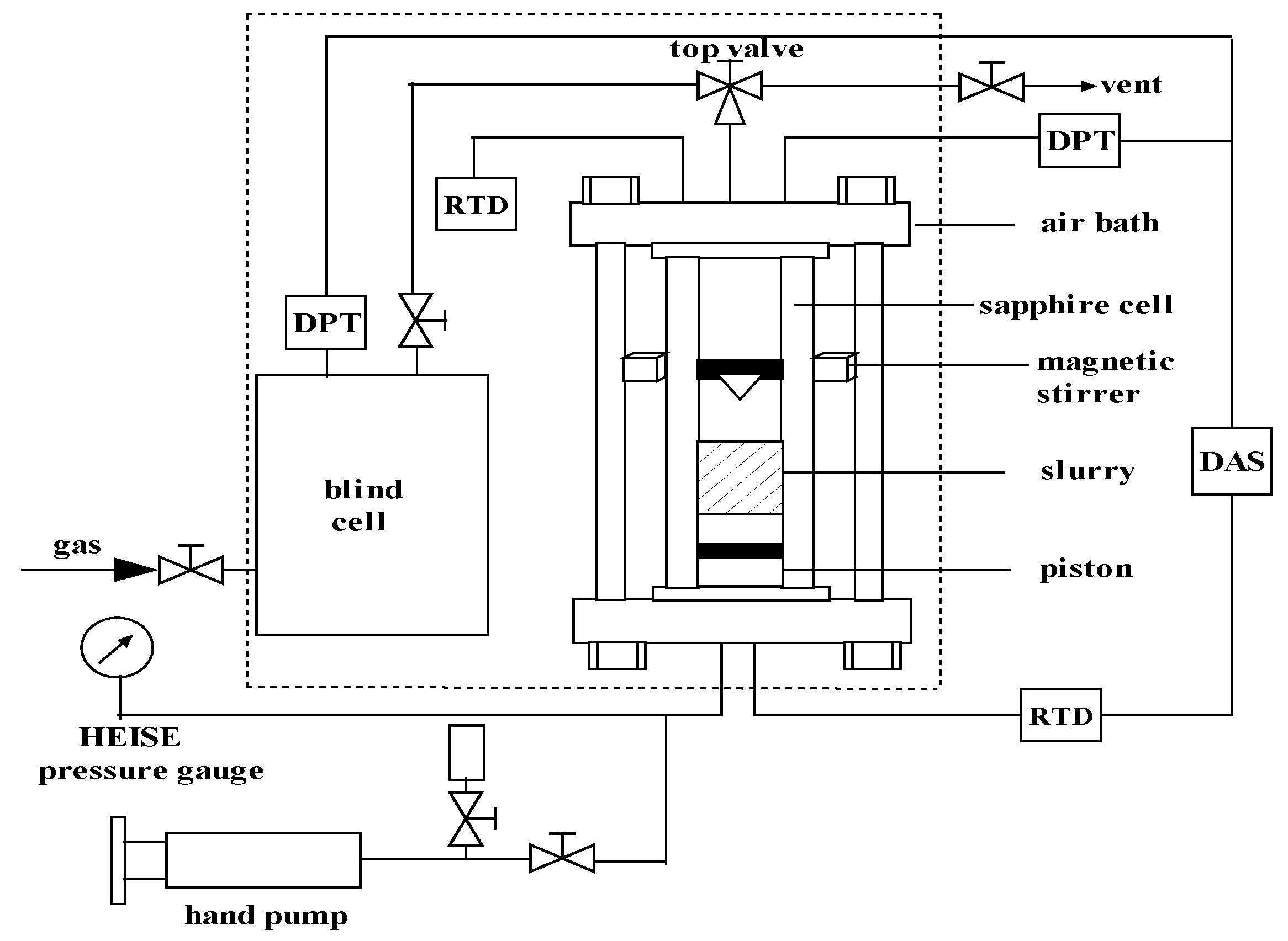
2.2. Experimental Apparatus

The experimental setup for measuring the separation performance is shown in Figure 1. A detailed description of both the apparatus and the experimental procedures is provided in our previous work [25,27].
A transparent sapphire cell and a steel blind cell are the main components of the apparatus, and both are installed in an air bath. The effective volumes of the sapphire cell and the blind cell together with the tubes connected to it are 60 cm3 and 112 cm3, respectively. The two cells are each designed to operate at a maximum working pressure of 20 MPa. A luminescence source (i.e., LG100H type) was fixed onto the outside of the cell to facilitate visual observation of the changes occurring during the experimental procedures. A secondary platinum resistance thermometer (type-pt100) temperature sensor provided information about temperature changes in the air bath. A calibrated Heise pressure gauge and differential pressure transducers were used to adjust the system pressure. The accuracies of the pressure and temperature are ±0.01 MPa and ±0.1 K, respectively. Changes of temperature and pressure in the system as a function of the elapsed time were recorded and displayed by a computer. Additionally, a rotary viscosimeter NDJ-8S was used to measure the viscosity of the slurry under the normal pressure and the specified temperature.

2.3. Experimental Procedures

Prior to the experiments, the sapphire cell was washed with warm soapy water, rinsed with distilled water, and dried. The clean sapphire cell was then loaded with a desired quantity of dry porous material (ZIF-8). To make the slurry, after adding ZIF-8, glycol and/or water was added, and the mixture was stirred until homogenous. Finally, the cell was installed into the apparatus. All air in the sapphire cell, the blind cell, and the tubes connected between the two cells was then removed by a vacuum pump. Thereafter, the blind cell was charged with the feed gas mixture. Subsequently, the air bath was turned on, and the temperature was set to a desired value. As soon as a constant temperature was achieved in the air bath and a constant pressure was achieved in the blind cell, as displayed on the computer, the feed gas mixture pressure in the blind cell was recorded as the initial pressure, p1. The intake valve of the sapphire cell was later opened slowly, thus allowing the feed gas mixture to flow into the sapphire cell from the blind cell. When the feed gas mixture pressure in the sapphire cell reached a desired value, the intake valve was closed, and the magnetic stirrer started working to promote gas-slurry mass transfer. The pressure of the remnant feed gas mixture in the blind cell was recorded as p2. During each experiment, the changes of the sapphire cell pressure with the time were recorded. When the sapphire cell pressure became stable, which was usually after two hours, the sapphire cell equilibrium pressure was recorded as pE. The sample from the equilibrium gas phase of the sapphire cell was collected under constant pressure, and then the component was analyzed by a HP 7890 gas chromatograph. At last, the height of the equilibrium slurry phase was measured, which was used for calculating the volume of the slurry since the sapphire cell inner radius is a constant 1.27 cm. After the experiment, the dry ZIF-8 material was obtained by placing the recovered slurry under vacuum at a temperature of 373.15 K. Then, an XRD 6000 X type SIMADU ray diffraction instrument was used for the diffraction analysis with Cu Kα radiation, a 40-kV tube voltage, a tube current of 40 mA, and a scanning rate of 2° min−1 in the range from 5° to 50°.

2.4. Data Processing

In this work, the adsorption capacity of a gas species in the slurry phase was calculated by mass balance [25,27], as described below.
The total number of moles of the feed gas mixtures (nt) that were injected into the sapphire cell was calculated according to:
n t = p 1 V t Z 1 R T p 2 V t Z 2 R T
where T represents the system temperature, p1 represents the initial pressure of the blind cell, p2 represents the remnant pressure of the blind cell after the gas injected to the sapphire cell, Vt is the effective volume of the blind cell together with the tubes connected to it, and R is the ideal gas constant. The compressibility factors (i.e., Z1 and Z2) were calculated using the Benedict-Webb-Rubin-Starling (BWRS) equation of state.
The total number of moles of gas (nE) of the equilibrium gas phase in the sapphire cell after reaching adsorption equilibrium was calculated by:
n E = p E V E Z E R T
where pE represents the equilibrium pressure of the sapphire cell and ZE represents the compressibility factor corresponding to T and pE. VE represents the effective volume of the equilibrium gas mixture phase in the sapphire cell at the end of each experiment.
The adsorption capacity of C3H6 (n1) and H2 (n2) in the porous slurry were calculated according to:
n 1 = n t × z 1 n E × y 1
n 2 = n t × z 2 n E × y 2
where z1 and y1 represent the mole concentration of C3H6 in the feed gas mixture and equilibrium gas mixture phases, respectively, and z2 and y2 represent the mole concentration of H2 in the feed gas mixture and equilibrium gas mixture phases, respectively.
Therefore, the apparent mole concentration of C3H6 (x1) and H2 (x2) in the equilibrium slurry phase can be calculated using the following formulas:
x 1 = n 1 n 1 + n 2
x 2 = n 2 n 1 + n 2
In this study, S, representing the apparent selectivity of C3H6 over H2 in the slurry, was calculated as follows:
S = x 1 / y 1 x 2 / y 2
The formula used to calculate the amount of gas ab/adsorbed in the ZIF-8 slurry is:
n x = n t n E
The amount of gas ab/adsorbed per unit volume size SV (mol/L) is:
S V = n x V

3. Results and Discussion

3.1. Adsorption of Gases with Different ZIF-8 Conditions

First, we compared the gas adsorption by the solid ZIF-8 and the ZIF-8 slurry, which was suspended in water with a mass fraction of 15 wt %. As shown in Figure 2, as the equilibrium pressure increases, the adsorption capacity of the materials for each pure gas component increased gradually. However, it should be noted that the H2 adsorption curves show more disparity under the different ZIF-8 conditions than those of C3H6, indicating that the solvent (water) has little effect on the C3H6 adsorption, but has a negative effect on H2 uptake. As a result, we expect that dispersing ZIF-8 in water will improve the separation selectivity of C3H6/H2.

3.2. Separation of C3H6/H2 in Different ZIF-8/Liquid Slurries

Because ZIF-8 shows different adsorption capacities for the gases (e.g., H2, C3H6) under different conditions, further separation experiments were carried out with mixtures of gases (C3H6/H2, 35/65 mol %) using ZIF-8 slurries containing different liquid media. Table 1 shows the selectivities in the separation of a C3H6/H2 mixture for solid ZIF-8, and slurries of ZIF-8/water, ZIF-8/glycol, and ZIF-8/water-glycol (20 wt %), where p0 and pE represent the initial and the equilibrium pressures in the sapphire cell, pE-C3H6 is the partial pressure of C3H6 in the equilibrium gas phase, and y1 and x1 are the mole concentration of C3H6 in the equilibrium gas phase and liquid phase, respectively. S represents the selectivity of C3H6 over H2. The concentration of ZIF-8 in the slurry is 20%. Table 1 shows that the gas separation factor using ZIF-8/water is better than that of the dry material. The separation factor for the ZIF-8/water slurry can reach 105.4 with 335 kPa of initial pressure. The lowest separation factor is observed with ZIF-8/glycol. This is because the viscosity of the glycol has a great influence on the gas-liquid mass transfer rate, and the glycol molecules that aggregate on the ZIF-8 surface prevent some gas molecules from accessing the material [28]. In addition, we found that the slurry made with water and 20% glycol also shows a good gas separation ability. Although the gas separation factor of this system is smaller than that of the ZIF-8/water slurry, it still maintains a high separation factor (81.8) with the same initial pressure.
Based on our experimental results, we found that water is the best solvent for ZIF-8, as it is the cheapest and easiest to acquire. The drawbacks of using the ZIF-8/water slurry include material agglomeration and precipitation of the material, which can then get stuck to the walls of the sapphire cell during the experiments. This slurry also has a problem with bubbling during the gas desorption process, as shown in Figure 3. To overcome all these challenges, glycol can be added, which greatly helps to prevent bubbling, lowers the freezing point, and allows for the uniform dispersion of the ZIF-8 material in the slurry. In addition, the slurry with added glycol also maintains a good separation performance. The glycol is hydrophilic and easily dissolved in water. In addition, the glycol has colloidal properties that can keep the ZIF-8 material suspended in the slurry and prevent its agglomeration. During the desorption process, the gas bubbles can burst quickly, which inhibits foaming, as shown in Figure 4. The glycol molecules in the solvent gather at the ZIF-8 surface, forming a membrane akin to a glycol-water molecular film [28]. In addition, the specified amount of glycol helps transfer gas between the ZIF-8 and the solvent, thus improving the gas-liquid mass transfer rate.

3.3. Effect of Variable Experimental Parameters on the Separation of C3H6/H2 Using Different ZIF-8/Liquid Media

In this section, a series of experiments was carried out in order to explore the effects of the solid content, initial pressure, and temperature on the separation of C3H6/H2 and determine suitable operating conditions. The results for each parameter are given in Table 2, Table 3 and Table 4, respectively.
According to Table 2, as the solid content increases, the selectivity (S) for C3H6 over H2 gradually increases, and the C3H6 composition in the equilibrium gas phase gradually decreases, indicating a better gas separation. The C3H6 composition in the gas phase (y1) only changed slightly when the solid content was increased from 20 to 25% compared to the increase from 5 to 20%. As such, increased solid content enhanced the separation performance, but an excessive solid content in the slurry led to increased viscosity, making the gas-liquid mass transfer rate decrease. Thus, taking both the separation efficiency and flow behaviors into consideration, the solid content of ZIF-8 in the slurry should not exceed 20% for practical use.
Table 3 shows the effect of the equilibrium pressure on the separation performance of the gas mixture. With the increase of initial pressure (p0), the equilibrium pressure in the gas phase gradually increased, as expected. However, the C3H6 composition (y1) and C3H6 selectivity (S) in the slurry phase did not show any particular trend, as an increase was observed first, followed by a decrease, indicating that the optimal gas separation (128.4) was achieved when the pressure was controlled in the appropriate range. This can be attributed to the fact that as the pressure increased, the partial pressure of each component also increased. Compared to H2, more C3H6 was dissolved in the slurry at low equilibrium pressures. With the increase of the equilibrium pressure, the amount of adsorbed C3H6 in the ZIF-8 slurry gradually tends to saturate, however, the amount of adsorbed H2 continues to increase over a large range of equilibrium pressures. We found that maintaining the initial pressure at approximately 700 kPa provides very good separation. Therefore, the separation of a C3H6/H2 gas mixture was investigated at different temperatures with the initial pressure maintained at approximately 700 kPa, as shown in Table 4.
As shown in Table 4, as the temperature decreased, the gas separation factor gradually increased. Thus, temperature is an important factor for the separation of these gas mixtures. High temperatures are not conducive to selectivity when using the slurry. This is because the amount of adsorbed C3H6 in the slurry is higher than that of H2, and when temperature increases, the reduction in adsorption for C3H6 in the slurry is greater than that of H2. Therefore, temperature has a greater influence on the adsorption of C3H6 than that of H2. Reducing the temperature caused the amount of gas dissolved in the slurry to increase, and the increased temperature was only beneficial for the desorption of the gas. For a more in-depth understanding of the effect of temperature on gas adsorption in the slurry, we compared the uptake of C3H6 in a ZIF-8/water-glycol (20%) slurry at two different temperatures. As shown in Figure 5, the gas is more soluble at a lower temperature, but as the equilibrium pressure is increased, the difference in the solubility between the two temperatures is reduced. This is mainly because as pressure increases, the adsorption approaches saturation, and the capacity for C3H6 in the slurry increases slowly.

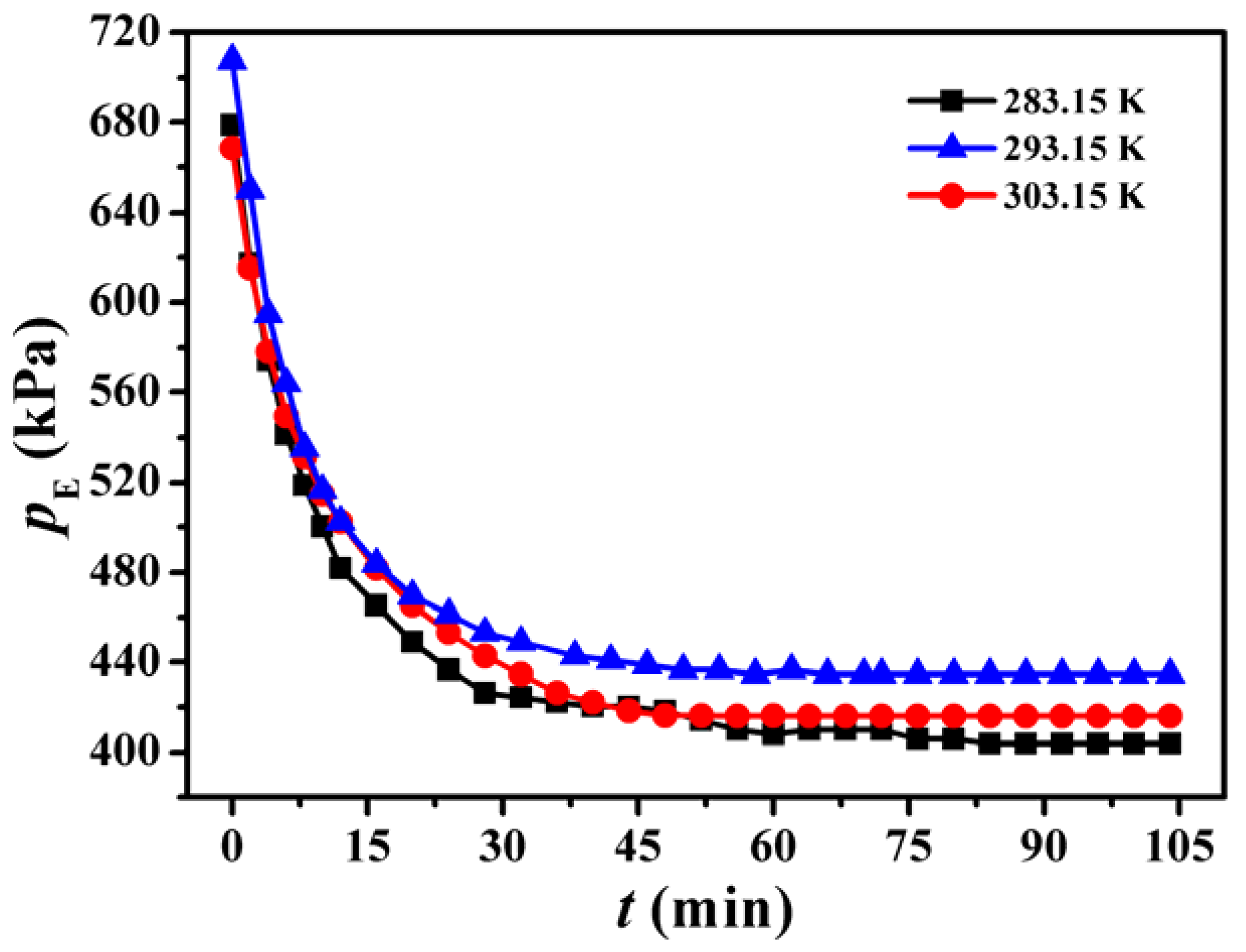
3.4. Kinetic Study of the H2/C3H6 Separation Process

To use the slurry in a practical production process, it is important to investigate the kinetics of the process, as they reflect the performances of the mass transfer rate and the driving force. Accordingly, we investigated the impact of the liquid media, the initial pressure, and temperature on the dynamic curve of the C3H6/H2 separation process. The results from each parameter are given in Figure 6, Figure 7, Figure 8 and Figure 9, respectively.
A process dynamic curve of the separation of C3H6/H2 in different slurries is shown in Figure 6. The dynamic change in the slurry containing only water is basically identical to that of the slurry with 20% glycol. The time to equilibrium and pressure drop are also almost the same, indicating that in a ZIF-8/slurry, adding a small amount of glycol to water does not affect the adsorption rate or efficiency of mass transfer. The ZIF-8/glycol slurry balance time is prolonged, the pressure drop is relatively small, and the effect of mass transfer is relatively poor. These results prove that the selection of a ZIF-8/water-glycol (20%) slurry can improve the slurry state and does not affect the gas-liquid mass transfer. However, if too much glycol is added or the slurry is composed of pure glycol, the glycol film thickness increases, causing the mass transfer rate and driving force to decrease.
As shown in Figure 7, under the same initial pressure, solid ZIF-8 can quickly reach equilibrium (20 min), but the pressure drop is less than that observed for the slurries. This is mainly due to the aggregation of the dry materials. Internal materials can hardly make contact with the gas, resulting in poor gas-solid mass transfer. The adsorption separation process was completed quickly. For the slurries, continuous stirring can ensure homogenous adsorption of the gas within the slurry. As a result, good gas-liquid mass transfer is observed, and the time required for the mass transfer process to occur is longer.
In Figure 8, we compare the dynamic curves at the different initial pressures. At low pressure, the dynamic curve is steep and the equilibrium time is fast. At high pressure, the pressure drop is relatively large, mainly because as the initial pressure increases, more of the gas enters the solution to be separated, and the equilibrium is pushed towards the separated product. Therefore, the time for the gas-liquid mass transfer process is increased. After the reaction, the mass transfer rate tends to be slow. Figure 9 compares the dynamic changes at different temperatures. The results show that increasing the temperature is helpful for accelerating the reaction rate. High temperatures allow the pressure to reach equilibrium in a relatively short time. Low temperatures are conducive to dissolving the gas and pushing the equilibrium towards separation. The reaction shows a greater pressure drop at lower temperatures. However, the difference in the equilibrium time and pressure drop at different temperatures and the different initial pressures is not very obvious, so the temperature and the initial pressure do not have a significant effect on the dynamics.

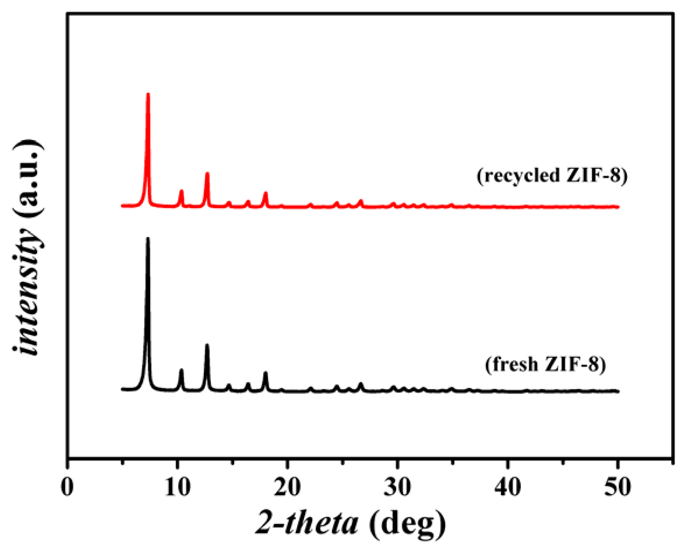
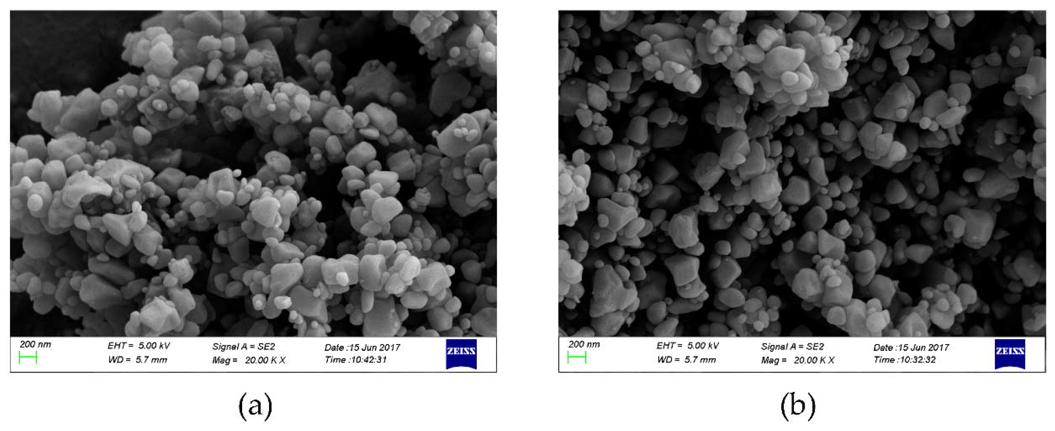
3.5. Recovery and Reusability of the ZIF-8 Slurry

To ensure the financial feasibility of this process, the slurry should be able to be reused several times before being replaced with a fresh slurry. The results of the separation of a C3H6/H2 gas mixture using recycled ZIF-8/glycol-water slurries are shown in Table 5. Table 5 shows that after using the slurry three times, the selectivity (S) of C3H6 over H2 is still approximately 138. Therefore, the material does not show any change in its gas separation capabilities, indicating that it could be reused on an industrial scale.
A comparison of the XRD patterns of the fresh ZIF-8 and ZIF-8 samples that were in over 10 experiments is shown in Figure 10. From Figure 10, we can see that there is no difference in the two XRD patterns, and all peaks completely overlap. In addition, as shown in Figure 11, it can be found that the morphology of ZIF-8 samples that were used in over 10 experiments is almost the same with that of the fresh ZIF-8, indicating that the ZIF-8 remains intact after repeated use.

4. Conclusions

In this work, a porous slurry composed of ZIF-8/glycol-water was selected for enriched hydrogen from a mixture with propylene. We found that the selectivity (S) of C3H6 over H2 in ZIF-8/water is higher than that for dry ZIF-8. However, because of the hydrophobicity of ZIF-8, using only water as the liquid media causes the ZIF-8 slurry to stick to the walls of the sapphire cell during the adsorption process and causes problematic bubbling during the desorption process, which decreases the mass transfer rate. A slurry made with 20% glycol in an aqueous solution achieves good gas separation without affecting the mass transfer rate. Low temperature, a slurry containing approximately 20% glycol, and a relatively high pressure efficiently enable the separation of hydrogen from the tail-gas component, propylene. The slurry was completely reusable for at least three cycles. The structure of the ZIF-8 material was not altered after repeated use, meaning the material can likely be reused more than three times on an industrial scale.

Author Contributions

Conceptualization, B.L. and G.C.; Formal analysis, H.L., X.G., B.L., and G.C.; Funding acquisition, B.L. and G.C.; Investigation, H.L., X.G., C.J., W.C., L.Y., and C.S.; Supervision, B.L. and G.C.; Writing—original draft, H.L.; Writing—review and editing, B.L.

Funding

Financial support was received from the National Natural Science Foundation of China (21522609, 21636009) and the Science Foundation of the China University of Petroleum, Beijing (No. 2462018BJC004).

Acknowledgments

Financial support was received from the National Natural Science Foundation of China (21522609, 21636009) and the Science Foundation of the China University of Petroleum, Beijing (No. 2462018BJC004), both of which are gratefully acknowledged.

Conflicts of Interest

The authors declare no conflict of interest.

References

  1. Adhikari, S.; Fernando, S.D.; To, S.D.F.; Bricka, R.M.; Steele, P.H.; Haryanto, A. Conversion of Glycerol to Hydrogen via a Steam Reforming Process over Nickel Catalysts. Energy Fuels 2008, 22, 1220–1226. [Google Scholar] [CrossRef]
  2. Bohme, U.; Barth, B.; Paula, C.; Kuhnt, A.; Schwieger, W.; Mundstock, A.; Caro, J.; Hartmann, M. Ethene/ethane and propene/propane separation via the olefin and paraffin selective metal-organic framework adsorbents CPO-27 and ZIF-8. Langmuir 2013, 29, 8592–8600. [Google Scholar] [CrossRef] [PubMed]
  3. Faria, W.; Dieguez, L.; Schmal, M. Autothermal reforming of propane for hydrogen production over Pd/CeO2/Al2O3 catalysts. Appl. Catal. B Environ. 2008, 85, 77–85. [Google Scholar] [CrossRef]
  4. Thomas, J.M.; Raja, R.; Johnson, B.F.; Hermans, S.; Jones, M.D.; Khimyak, T. Bimetallic catalysts and their relevance to the hydrogen economy. Ind. Eng. Chem. Res. 2003, 42, 1563–1570. [Google Scholar] [CrossRef]
  5. Kolb, G.; Zapf, R.; Hessel, V.; Löwe, H. Propane steam reforming in micro-channels—Results from catalyst screening and optimisation. Appl. Catal. A Gen. 2004, 277, 155–166. [Google Scholar] [CrossRef]
  6. Mundstock, A.; Wang, N.; Friebe, S.; Caro, J. Propane/propene permeation through Na-X membranes: The interplay of separation performance and pre-synthetic support functionalization. Microporous Mesoporous Mater. 2015, 215, 20–28. [Google Scholar] [CrossRef]
  7. Zhang, B.; Tang, X.; Li, Y.; Xu, Y.; Shen, W. Hydrogen production from steam reforming of ethanol and glycerol over ceria-supported metal catalysts. Int. J. Hydrog. Energy 2007, 32, 2367–2373. [Google Scholar] [CrossRef]
  8. Suarez, P.A.Z.; Dullius, J.E.L.; Einloft, S.; Souza, R.F.D.; Dupont, J. The use of new ionic liquids in two-phase catalytic hydrogenation reaction by rhodium complexes. Polyhedron 1996, 15, 1217–1219. [Google Scholar] [CrossRef]
  9. Ramachandran, R.; Menon, R.K. An overview of industrial uses of hydrogen. Int. J. Hydrog. Energy 1998, 23, 593–598. [Google Scholar] [CrossRef]
  10. Wang, X.; Li, M.; Li, S.; Wang, H.; Wang, S.; Ma, X. Hydrogen production by glycerol steam reforming with/without calcium oxide sorbent: A comparative study of thermodynamic and experimental work. Fuel Process. Technol. 2010, 91, 1812–1818. [Google Scholar] [CrossRef]
  11. Jepsen, J.; Milanese, C.; Puszkiel, J.; Girella, A.; Schiavo, B.; Lozano, G.; Capurso, G.; von Colbe, J.B.; Marini, A.; Kabelac, S.; et al. Fundamental Material Properties of the 2LiBH4-MgH2 Reactive Hydride Composite for Hydrogen Storage: (II) Kinetic Properties. Energies 2018, 11, 1170. [Google Scholar] [CrossRef]
  12. Resini, C.; Herrera Delgado, M.C.; Arrighi, L.; Alemany, L.J.; Marazza, R.; Busca, G. Propene versus propane steam reforming for hydrogen production over Pd-based and Ni-based catalysts. Catal. Commun. 2005, 6, 441–445. [Google Scholar] [CrossRef]
  13. Resini, C.; Arrighi, L.; Concepcionherreradelgado, M.; Angeleslarrubiavargas, M.; Alemany, L.; Riani, P.; Berardinelli, S.; Marazza, R.; Busca, G. Production of hydrogen by steam reforming of C3 organics over Pd–Cu/γγ-Al2O3 catalyst. Int. J. Hydrog. Energy 2006, 31, 13–19. [Google Scholar] [CrossRef]
  14. Collins, J.P.; Schwartz, R.W.; Sehgal, R.; Ward, T.L.; Brinker, C.J.; Hagen, G.P.; Udovich, C.A. Catalytic Dehydrogenation of Propane in Hydrogen Permselective Membrane Reactors. Ind. Eng. Chem. Res. 1996, 35, 4398–4405. [Google Scholar] [CrossRef]
  15. Shigaki, N.; Mogi, Y.; Haraoka, T.; Sumi, I. Reduction of Electric Power Consumption in CO2-PSA with Zeolite 13X Adsorbent. Energies 2018, 11, 900. [Google Scholar] [CrossRef]
  16. Ockwig, N.W.; Nenoff, T.M. Membranes for Hydrogen Separation. Chem. Rev. 2007, 107, 4078–4110. [Google Scholar] [CrossRef] [PubMed]
  17. Feng, W.; Wang, Q.; Zhu, X.; Kong, Q.; Wu, J.; Tu, P. Influence of Hydrogen Sulfide and Redox Reactions on the Surface Properties and Hydrogen Permeability of Pd Membranes. Energies 2018, 11, 1127. [Google Scholar] [CrossRef]
  18. Dubois, L.; Thomas, D. CO2 Absorption into Aqueous Solutions of Monoethanolamine, Methyldiethanolamine, Piperazine and their Blends. Chem. Eng. Technol. 2009, 32, 710–718. [Google Scholar] [CrossRef]
  19. Zhang, X.-X.; Xiao, P.; Zhan, C.-H.; Liu, B.; Zhong, R.-Q.; Yang, L.-Y.; Sun, C.-Y.; Liu, H.; Pan, Y.; Chen, G.-J.; et al. Separation of Methane/Ethylene Gas Mixtures Using Wet ZIF-8. Ind. Eng. Chem. Res. 2015, 54, 7890–7898. [Google Scholar] [CrossRef]
  20. Baker, R.W. Future directions of membrane gas separation technology. Ind. Eng. Chem. Res. 2002, 41, 139–1411. [Google Scholar] [CrossRef]
  21. O’Reilly, N.; Giri, N.; James, S.L. Porous liquids. Chemistry 2007, 13, 3020–3025. [Google Scholar] [CrossRef] [PubMed]
  22. Giri, N.; Del Popolo, M.G.; Melaugh, G.; Greenaway, R.L.; Ratzke, K.; Koschine, T.; Pison, L.; Gomes, M.F.; Cooper, A.I.; James, S.L. Liquids with permanent porosity. Nature 2015, 527, 216–220. [Google Scholar] [CrossRef] [PubMed]
  23. Zhang, J.; Chai, S.H.; Qiao, Z.A.; Mahurin, S.M.; Chen, J.; Fang, Y.; Wan, S.; Nelson, K.; Zhang, P.; Dai, S. Porous liquids: A promising class of media for gas separation. Angew. Chem. Int. Ed. Engl. 2015, 54, 932–936. [Google Scholar] [CrossRef] [PubMed]
  24. Lei, Z.; Dai, C.; Song, W. Adsorptive absorption: A preliminary experimental and modeling study on CO2 solubility. Chem. Eng. Sci. 2015, 127, 260–268. [Google Scholar] [CrossRef]
  25. Liu, H.; Liu, B.; Lin, L.C.; Chen, G.; Wu, Y.; Wang, J.; Gao, X.; Lv, Y.; Pan, Y.; Zhang, X.; et al. A hybrid absorption-adsorption method to efficiently capture carbon. Nat. Commun. 2014, 5, 5147. [Google Scholar] [CrossRef] [PubMed]
  26. Shan, W.; Fulvio, P.F.; Kong, L.; Schott, J.A.; Do-Thanh, C.L.; Tian, T.; Hu, X.; Mahurin, S.M.; Xing, H.; Dai, S. New Class of Type III Porous Liquids: A Promising Platform for Rational Adjustment of Gas Sorption Behavior. ACS Appl. Mater. Interfaces 2018, 10, 32–36. [Google Scholar] [CrossRef] [PubMed]
  27. Pan, Y.; Li, H.; Zhang, X.-X.; Zhang, Z.; Tong, X.-S.; Jia, C.-Z.; Liu, B.; Sun, C.-Y.; Yang, L.-Y.; Chen, G.-J. Large-scale synthesis of ZIF-67 and highly efficient carbon capture using a ZIF-67/glycol-2-methylimidazole slurry. Chem. Eng. Sci. 2015, 137, 504–514. [Google Scholar] [CrossRef]
  28. Liu, H.; Pan, Y.; Liu, B.; Sun, C.; Guo, P.; Gao, X.; Yang, L.; Ma, Q.; Chen, G. Tunable integration of absorption-membrane-adsorption for efficiently separating low boiling gas mixtures near normal temperature. Sci. Rep. 2016, 6, 21114. [Google Scholar] [CrossRef] [PubMed] [Green Version]
  29. Banerjee, R.; Phan, A.; Wang, B.; Knobler, C.; Furukawa, H.; O’Keeffe, M.; Yaghi, O.M. High-throughput synthesis of zeolitic imidazolate frameworks and application to CO2 capture. Science 2008, 319, 939–943. [Google Scholar] [CrossRef] [PubMed]
  30. Navarro, M.; Seoane, B.; Mateo, E.; Lahoz, R.; de la Fuente, G.F.; Coronas, J. ZIF-8 micromembranes for gas separation prepared on laser-perforated brass supports. J. Mater. Chem. A 2014, 2, 11177–11184. [Google Scholar] [CrossRef] [Green Version]
  31. Park, K.S.; Ni, Z.; Cote, A.P.; Choi, J.Y.; Huang, R.; Uribe-Romo, F.J.; Chae, H.K.; O’Keeffe, M.; Yaghi, O.M. Exceptional chemical and thermal stability of zeolitic imidazolate frameworks. Proc. Natl. Acad. Sci. USA 2006, 103, 10186–10191. [Google Scholar] [CrossRef] [PubMed] [Green Version]
  32. Férey, G. Hybrid porous solids: Past, present, future. Chem. Soc. Rev. 2008, 37, 191–214. [Google Scholar] [CrossRef] [PubMed]
  33. Li, J.R.; Sculley, J.; Zhou, H.C. Metal-organic frameworks for separations. Chem. Rev. 2012, 112, 869–932. [Google Scholar] [CrossRef] [PubMed]
  34. Li, Z.; Xu, G.; Liu, B.; Lv, X.; Chen, G.; Sun, C.; Xiao, P.; Sun, Y. Molecular Simulation Studies of Flue Gas Purification by Bio-MOF. Energies 2015, 8, 11531–11545. [Google Scholar] [CrossRef] [Green Version]
  35. Rodenas, T.; Luz, I.; Prieto, G.; Seoane, B.; Miro, H.; Corma, A.; Kapteijn, F.; Xamena, F.X.L.I.; Gascon, J. Metal-organic framework nanosheets in polymer composite materials for gas separation. Nat. Mater. 2015, 14, 48–55. [Google Scholar] [CrossRef] [PubMed]
  36. Wang, L.; Yang, Y.; Shen, W.; Kong, X.; Li, P.; Yu, J.; Rodrigues, A.E. Experimental evaluation of adsorption technology for CO2 capture from flue gas in an existing coal-fired power plant. Chem. Eng. Sci. 2013, 101, 615–619. [Google Scholar] [CrossRef]
  37. Liu, H.; Wang, J.; Chen, G.; Liu, B.; Dandekar, A.; Wang, B.; Zhang, X.; Sun, C.; Ma, Q. High-efficiency separation of a CO2/H2 mixture via hydrate formation in W/O emulsions in the presence of cyclopentane and TBAB. Int. J. Hydrog. Energy 2014, 39, 7910–7918. [Google Scholar] [CrossRef]
Figure 1. Schematic diagram of the experimental apparatus used for separation performance measurements: RTD, resistance thermocouple detector; DPT, differential pressure transducer; and DAS, data acquisition system.
Energies 11 01890 g001
Figure 2. Adsorption isotherms of different pure gases (H2, C3H6) with different zeolitic imidazolate framework-8 (ZIF-8) conditions at 293 K: (a) (H2), (b) (C3H6), b1 (with solid ZIF-8) and b2 (with a ZIF-8 slurry, which was suspended in water with a mass concentration of 15 wt %).
Energies 11 01890 g002
Figure 3. The morphology of the ZIF-8/water slurry during the separation of a C3H6/H2 mixture. (a) Fresh ZIF-8/water slurry; (b) separation equilibrium slurry; and (c) gas desorption process for ZIF-8/water slurry.
Energies 11 01890 g003
Figure 4. The morphology of the ZIF-8/water-glycol slurry during the separation of a C3H6/H2 mixture. (a) Fresh ZIF-8/water-glycol slurry; (b) separation equilibrium slurry; and (c) gas desorption process for the slurry.
Energies 11 01890 g004
Figure 5. Solubility curve of C3H6 in the ZIF-8/water-glycol slurry where the mass ratio between water and glycol in the solution was specified to 4:1 with 20 wt % ZIF-8 at different temperatures.
Energies 11 01890 g005
Figure 6. Kinetic curves for the ZIF-8 slurry containing different liquid media at 293.15 K and fixed initial pressure of 700 kPa. The solid content of ZIF-8 is 20 wt % for each slurry. The mass ratio between water and glycol in the ZIF-8/water-glycol slurry is specified to 4:1.
Energies 11 01890 g006
Figure 7. Kinetic curves for the solid ZIF-8 or the ZIF-8 slurry at 293.15 K and fixed initial pressure of 780 kPa. The solid content of ZIF-8 is 20 wt % for the ZIF-8 slurry. The mass ratio between water and glycol in the ZIF-8/water-glycol slurry is specified to 4:1.
Energies 11 01890 g007
Figure 8. Comparison of the dynamic curves under different inlet pressures at 293.15 K. The mass ratio between water and glycol in the ZIF-8/water-glycol (20%) slurry was specified to 4:1 with 20 wt % ZIF-8.
Energies 11 01890 g008
Figure 9. Comparison of the dynamic curves at different temperatures. The mass ratio between water and glycol in the ZIF-8/water-glycol (20%) slurry was specified to 4:1 with 20 wt % ZIF-8.
Energies 11 01890 g009
Figure 10. Comparison of the X-ray diffraction patterns of fresh ZIF-8 and recycled ZIF-8 from a ZIF-8/water-glycol slurry after the separation of C3H6/H2.
Energies 11 01890 g010
Figure 11. Comparison of the SEM images of fresh ZIF-8 and recycled ZIF-8 from a ZIF-8/water-glycol slurry after the separation of C3H6/H2. (a) fresh ZIF-8; (b) recycled ZIF-8.
Energies 11 01890 g011
Table 1. Comparison of the separation performance for a C3H6 (1) + H2 (2) gas mixture (z1 = 0.35) using a solid ZIF-8 (S1), ZIF-8/water (S2) slurry, ZIF-8/glycol (S3) slurry, or ZIF-8/water-glycol (S4) slurry, where the mass ratio between water and glycol was 4:1 at 293.15 K. The ZIF-8 content in all the slurries was fixed at 20 wt %.
No.p0/kPapE/kPapE-C3H6/kPay1/mol %x1/mol %S
S1331.3247.97.4365.160.3
S2335.3197.15.72.975.9105.4
S3345.5227.656.224.756.33.9
S4333.3191.06.13.27381.8
Table 2. Separation results for a C3H6 (1) + H2 (2) gas mixture (z1 = 0.35) using ZIF-8/water-glycol slurries where the mass ratio between water and glycol in the solution was specified to 4:1 with five different ZIF-8 mass fractions at 293.15 K and at nearly the same initial pressure (p0) of approximately 680 kPa. S represents the apparent selectivity of C3H6 over H2 in a given slurry. η represents the viscosity of the slurries corresponding to different ZIF-8 mass fractions at 293.15 K.
mF/wt %p0/kPapE/kPapE-C3H6/kPay1/mol %x1/mol %Sη/mPa·s
5.2664.8540.8140.626.086.017.52.78
10.1693.2480.155.211.582.135.34.02
15.3697.3435.325.75.982.776.211.17
20.2689.2410.616.03.983.9128.419.03
25.6685.1404.59.72.476.7133.933.05
Table 3. Separation results for C3H6 (1) + H2 (2) gas mixture (z1 = 0.35) by using ZIF-8/water-glycol slurry where the mass ratio between water and glycol in liquid was specified to 4:1 with 20 wt % ZIF-8 at 293.15 K and different initial pressures.
p0/kPapE/kPapE-C3H6/kPay1/mol %x1/mol %S
333.3193.06.23.265.657.7
689.2410.616.03.983.9128.4
1034.8651.630.64.780.985.9
Table 4. Separation results for C3H6 (1) + H2 (2) gas mixtures (z1 = 0.35) using a ZIF-8/water-glycol slurry where the mass ratio between water and glycol in the solution was specified to 4:1 with 20 wt % ZIF-8 at nearly the same initial pressure of approximately 700 KPa, but with different temperatures. S is the apparent selectivity of C3H6 over H2 in the slurry.
TpE/kPapE-C3H6/kPay1/mol %x1/mol %S
313.2433.030.37.082.964.4
303.2426.919.24.576.970.6
293.2416.914.63.583.3137.5
274.2390.39.42.478.0144.2
Table 5. Separation results for a C3H6 (1) + H2 (2) gas mixture (z1 = 0.35) using recycled ZIF-8/glycol-water slurries where the mass ratio between water and glycol in the solution was specified to 4:1 at 293.15 K, and the same initial pressures (p0) of approximately 680 kPa were used.
Repetition Timesp0/kPapE/kPapE-C3H6/kPay1/mol %x1/mol %S
0689.2416.714.63.583.3137.5
1685.1410.615.63.884.0132.9
2687.3411.714.83.683.8138.5

