Article

Effects of Foreign Metal Object on Soft-Switching Conditions of Class-E Inverter in WPT

School of Electric Power Engineering, South China University of Technology, Guangzhou 510641, China
*
Author to whom correspondence should be addressed.
Energies 2018, 11(8), 1926; https://doi.org/10.3390/en11081926
Submission received: 22 June 2018 / Revised: 15 July 2018 / Accepted: 17 July 2018 / Published: 24 July 2018

Abstract

:
A foreign metal object will deteriorate the performance of wireless power transfer (WPT) systems and cause insecurity issues. Therefore, the influence principles and rules of foreign metal objects on soft-switching conditions of Class-E inverters and the performance of WPT systems are developed in this paper. The effects of different metal materials on coil parameters at different frequencies and positions are analyzed first, then the effects of foreign metal objects on soft-switching conditions of Class-E inverters and the power transfer capability of WPT systems are investigated. Principle analyses and simulation results demonstrate that there are significantly different effects on the soft-switching conditions and power transfer when a foreign metal object is placed near the transmitter coil or the receiver coil. In addition, the monotonicity of the variation in power transfer also depends on the position of the foreign metal object. Finally, a WPT experimental prototype with a Class-E inverter is implemented to verify the influence principles and rules of foreign metal objects. The experimental results are highly consistent with the principle analyses and simulation results.

1. Introduction

With the continuous development of wireless power transfer (WPT) technology and its commercialization process, its security issues attract more and more attention [1,2,3,4]. One such issue is that a foreign metal object will deteriorate the WPT system performance [5,6], and the eddy current of the metal object will cause heating problems, possibly causing a fire hazard [7]. Therefore, it is necessary to study the effects of foreign metal objects on WPT system.
Because a foreign metal object will change the relative permeability of the magnetic circuit of the coil and other related parameters, the impacts of a foreign metal object on parameters of the coil need to be studied. Reference [8] analyzes these impacts by using an efficient perturbation method and Born approximation. However, its analytical method is difficult to implement due to the complicated calculations. The changing rules of equivalent parameters caused by three typical materials, including iron, copper, and aluminum, are studied by a 3-D finite-element model coupled with an external circuit [9]. The results show that all three kinds of metal materials will reduce the inductance and increase the resistance of the coil, i.e., reduce the Q value. Furthermore, the variation of the coil parameters caused by a foreign metal object will change the resonant frequency of the system [6,9], thereby deteriorating the transfer efficiency. Reference [10] shows that the efficiency will decrease dramatically when a foreign metal object appears near the receiver coil, but it draws the conclusion from experiments without giving theoretical analysis. In addition, Reference [11] focuses on the heating problem caused by the metal object, and the theoretical and experimental results show that the heating phenomenon is very obvious around the edge of the coil.
Therefore, in order to cope with the problems caused by foreign metal objects, the method of using ferrite cores with proper distribution to eliminate the influence caused by the metal object is presented in Reference [12], and the method of enabling WPT through a metal encased device is also introduced in Reference [13]. Furthermore, some researchers propose the foreign object detection (FOD) method [1,14,15], which is an essential function to prevent the energy from being consumed in the form of heat. A method of load and metal object detection is presented in Reference [16]. The supply current and the transmitter coil voltage are monitored to determine the existence of the load or a foreign metal object. The experiment results indicate that the soft-switching conditions of the Class-E inverter will be invalid when the metal object approaches the transmitter coil, causing the Metal-Oxide-Semiconductor Field-Effect Transistor (MOSFET) to burn out. However, the reasons and details are not discussed in depth. In fact, all of the above papers only consider the thermal heating issue and the efficiency decrease when a foreign metal object is involved in the WPT system, and instead focus on the FOD method without discussing the impacts of the metal object on the WPT system’s performance, such as soft-switching conditions and power transfer capacity. Therefore, this paper specifically analyzes the effects of foreign metal objects on the soft-switching conditions of the Class-E inverter, and the relationship between the power transfer capacity and the distance between the coil and the foreign metal object is also presented.
In Section 2, a brief review of the operational characteristics of the Class-E inverter in WPT systems is introduced. The influence of two kinds of commonly used metal materials on coil parameters at different frequencies and different positions is then analyzed in Section 3. Considering one kind of particular metal material, since all of them have a similar effect at high frequency, the effects of a foreign metal object on the soft-switching conditions of the Class-E inverter is presented in Section 4. In addition, the power transfer capacity of the Class-E inverter will change due to the foreign metal object. The effect causing the power transfer to change monotonically or non-monotonically is also explained. The presented theoretical analysis is verified by an experimental prototype of a WPT system with a Class-E inverter, which is presented in Section 5.

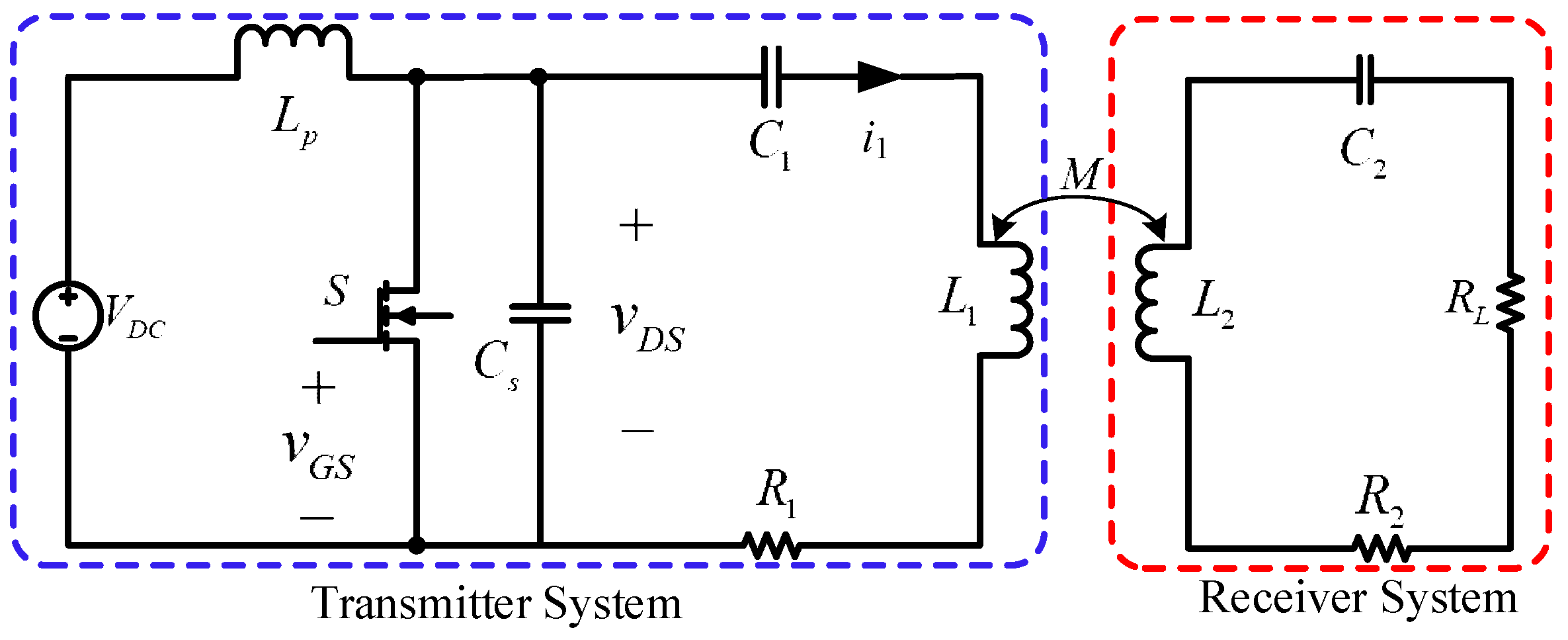
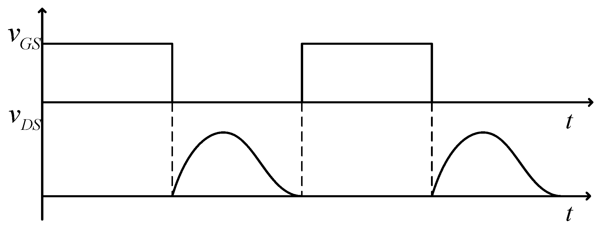
2. Idealized Operation of the Class-E Inverter in WPT System

The Class-E inverter is widely used in WPT system for it requires only one switch and the theoretical efficiency can be up to 100% when it works at zero voltage switching (ZVS) and zero derivative switching (ZDS) soft-switching conditions [17]. Assuming that the system uses series-series compensation topology, the schematic diagram of the Class-E inverter used in WPT system is shown in Figure 1, where the blue dotted box represents the Class-E inverter with transmitter coil and the red dotted box represents the receiver system.
Here, L1 and L2 denote the inductance of the transmitter coil and the receiver coil respectively, R1 and R2 denote the resistance of the transmitter coil and the receiver coil respectively, C1 and C2 denote the compensation capacitor of the transmitter system and the receiver system respectively, and RL denotes the load resistance. Generally, the receiver system is designed to work at resonance for improving the system efficiency, which means L2 is totally compensated by C2. As a result, the impedance of the receiver system seen from the transmitter side, i.e., reflected impedance, is a resistor Rr, i.e.,
R r = ( ω M ) 2 R 2 + R L = ( ω M ) 2 R 2
where R 2 denotes (R2 + RL). Therefore, Rr, R1, L1 and C1 make up the equivalent resonant network and the equivalent load of the Class-E inverter. If the Class-E inverter works ideally at ZVS and ZDS soft-switching conditions, i.e.,
v D S | t o n = 0   and   d v D S d t | t o n = 0
then the equivalent load impedance angle ϕ should be equal to 49.052° [17].
φ = arctan ω L 1 1 ω C 1 R 1 + R r = 49.052
In this condition, the transmitter system does not work under resonant state, and the ideal waveforms of the driver signal vGS, and the drain-to-source voltage vDS of the MOSFET are shown in Figure 2.
Actually, the power transmitted to the receiver side equals to the power absorbed by the reflected resistor Rr, so the output power Pout can be calculated as
P o u t = I 1 2 R r R L R 2 + R L ,
where I1 denotes the Root-Mean-Square (RMS) value of the current i1 in transmitter coil. Normally, when the inverter works near the optimal point, I1 can be approximately calculated as
I 1 = V D S 1 cos φ R 1 + R r
where VDS1 denotes first harmonic component of vDS.
The current I1 is related to the equivalent load impedance angle ϕ, so does the output power. Concretely, the decrease of ϕ will result in the increase of the output power.

3. Effects of Foreign Metal Object on Coil Parameters

The metal materials most commonly utilized in the electrical industry, such as iron, copper and aluminum, may change the relative permeability of the magnetic circuit of the coils in WPT. However, only the effects of iron and copper are investigated in this section, for copper and aluminum have the same relative permeability, and have almost identical effects on the coil parameters [9]. The relative permeability and conductivity of iron and copper are 5000, 1.04 × 10⁷ s/m and 1, 5.96 × 10⁷ s/m, respectively.
The structure of the helix coils and positions of the metal plate are shown in Figure 3, and the parameters of the helix coils and the metal plate are listed in Table 1, where the subscripts 1 and 2 denote the transmitter side and the receiver side, respectively.

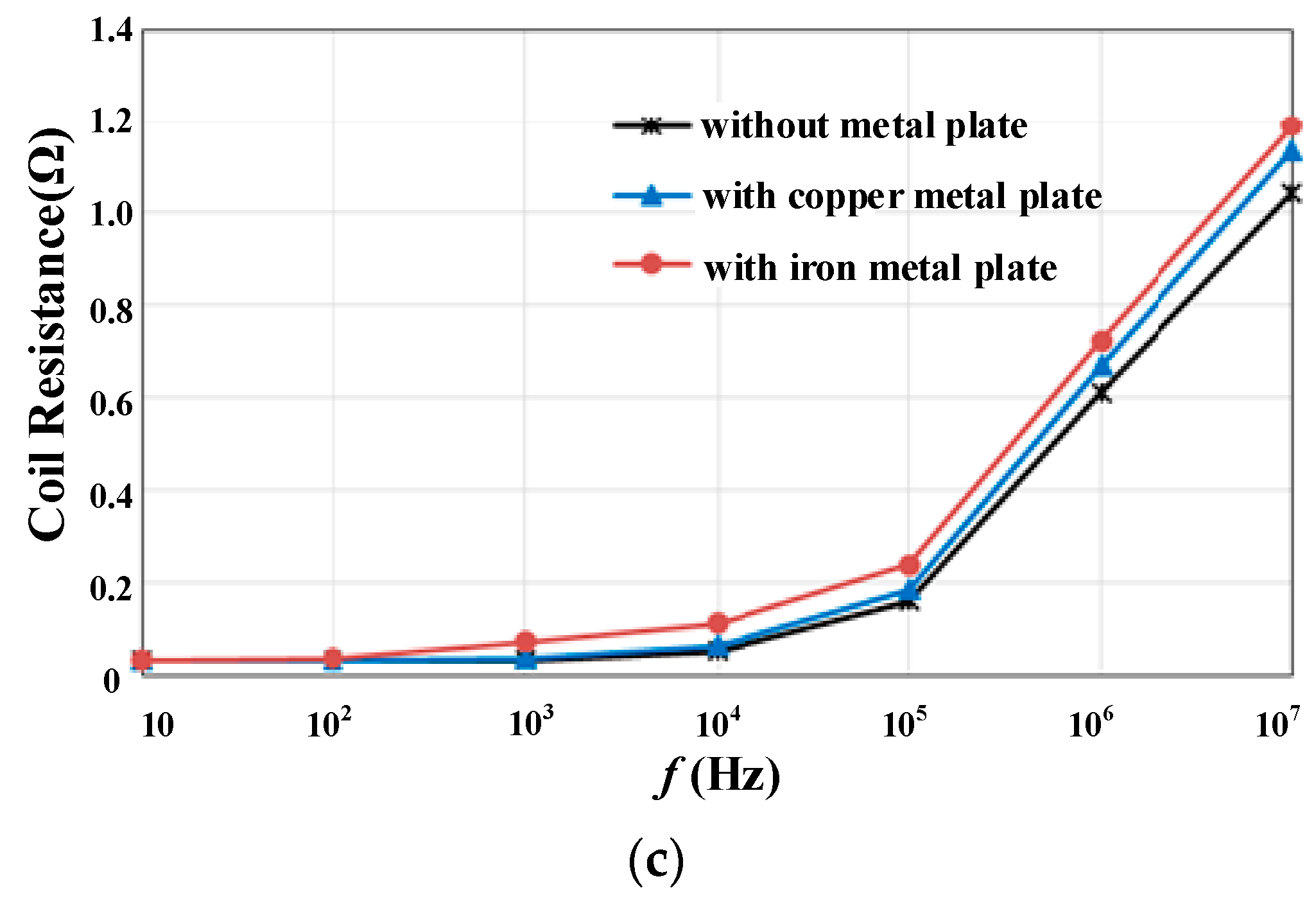
3.1. Effects of Different Frequencies

When the metal plate is placed close to one helix coil and far away from the other coil, the impacts of the metal plate on the other coil can be neglected.
The metal plate can be considered as a multi-turn flat coil, and the eddy current of the metal plate can be calculated by [18]
I s = j ω M 0 I r s + j ω L s
where M0 is the mutual inductance between the coil and the metal plate, I is the current of the coil, rs and Ls are the resistance and inductance of the metal plate respectively, and ω is the angular frequency.
At very low frequency, rs is a dominant factor to influence Is. Because the conductivity of iron is relatively low, its eddy current is small, which means the demagnetizing effect is negligible. In contrast, since the iron has comparatively high relative permeability, its magnetism gathering effect is greater than its demagnetizing effect, which enhances the original magnetic field and increases the inductance of the coil.
As the frequency increases, the resistant term can be omitted, so Equation (6) can be rewritten as
I s = M 0 I L s ,
which implies the eddy current is no longer affected by frequency when the frequency is high enough. Since the eddy current is larger at high frequency, the demagnetizing effect is dominant, causing the decrease of the inductance and mutual inductance [18].
As for coil resistance, the eddy current makes the current distribution in the helix coil more non-uniform, and the eddy current loss will reflect back to the coil in the form of resistance, leading the metal plate to increase the coil resistance regardless of frequency. The impacts of iron on the coil resistance are greater than that of copper, as the conductivity of iron is lower.
When the distance between the metal plate and the helix coil is set to 2 cm, the inductance, mutual inductance, and resistance of the helix coils versus frequency are shown in Figure 4a–c, respectively. The simulations are performed by using ANSYS Maxwell (version 16.0.2, Ansys, Inc., Canonsburg, PA, USA). The simulation results show that the iron plate will cause the inductance and the mutual inductance of the helix coil to increase at very low frequencies, while the copper plate will cause them to decrease. However, both iron and copper plate will cause the inductance and the mutual inductance of the helix coil to decrease at high frequency, and the curves tend to be flat as the frequency increases. In addition, the coil resistance increases as the frequency increases.
Generally, the WPT system works at high frequencies, so these two kinds of metal material have almost the same effects on coil parameters. It is obvious that the curves tend to be flat when the frequency ranges from 0.1 MHz to 10 MHz, and accordingly the middle frequency 1 MHz is selected as the operating frequency in the next sections. Although the coil resistance will change slightly with frequency, resulting in minor variation of the input and output power, changing the frequency does not affect the analysis presented in Section 4, except that the curves in Section 4 will move slightly up or down. Since the impact of iron metal material is even more severe, only the effects of iron plates on coil parameters at different positions are considered in the next sections.

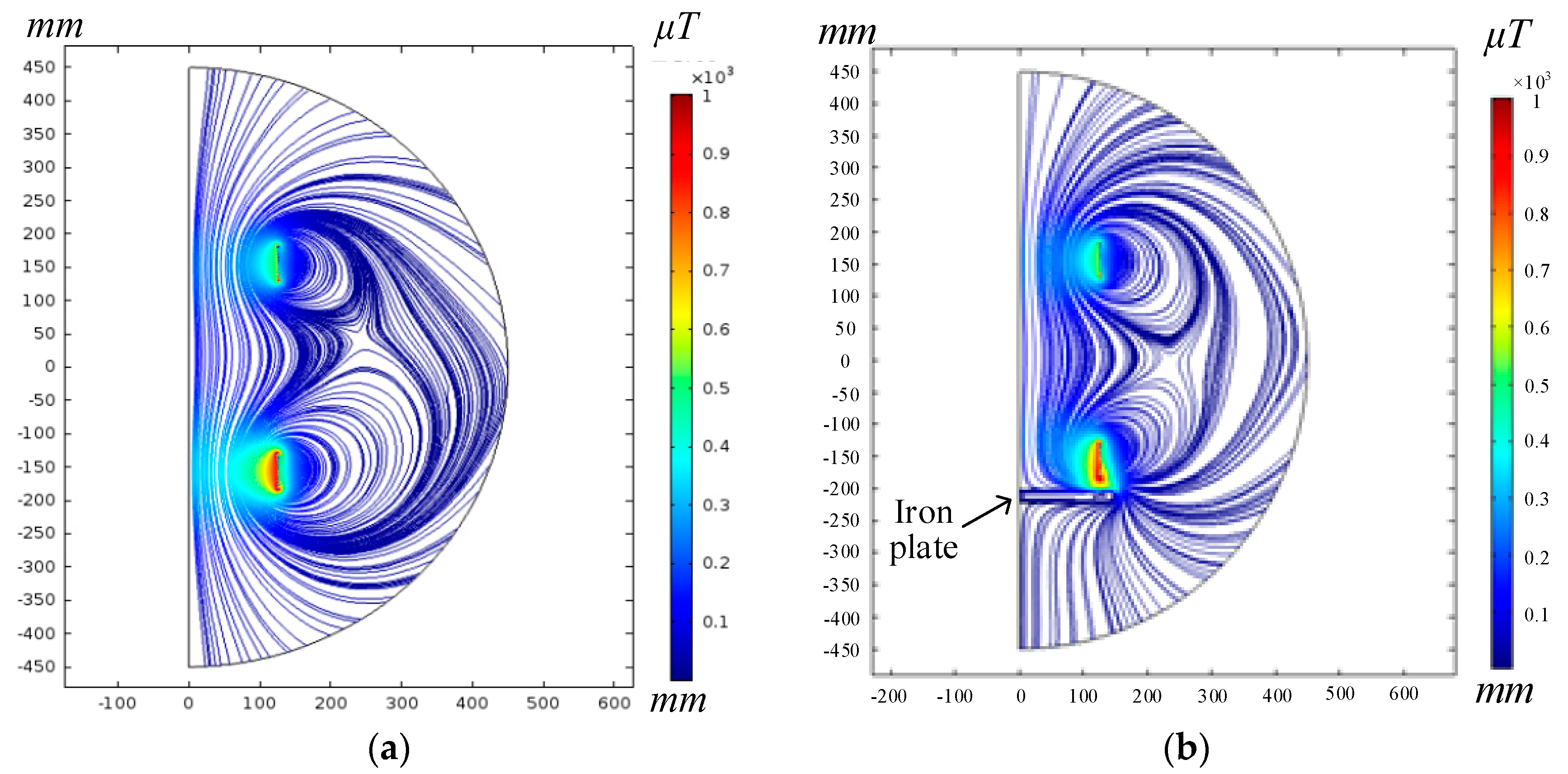
3.2. Effects of Different Positions of the Metal Plate

As shown in Figure 3, the iron plate is placed beside the receiver coil or the transmitter coil, i.e., along line l1 or l2, or at the outer side of the two coils, i.e., along line l3. The sectional view of the magnetic field map of the two helix coils with and without the iron plate are presented in Figure 5a,b. They are modeled in the 2D axisymmetric space using COMSOL (version 5.0.0.243, COMSOL Inc., Stockholm, Sweden). It can be seen that the distribution of the magnetic field is twisted by the iron plate. Concretely, the magnetic flux density behind the iron plate is much smaller.
The simulation results of the coil parameters versus the distance between the coil and metal plate are presented in Figure 6 and Figure 7, where the iron plate is placed along the line l2 and l3 respectively. It is obvious that the inductance will decrease while the resistance of the coil will increase, i.e., decrease the Q value. As the iron plate approaches the helix coil, especially when the distance is less than 5 cm, the influence of the iron plate is tremendous. As the distance increases, the parameters of the coil get closer to their corresponding rated values.

4. Effects of Foreign Metal Object on Soft-Switching Conditions

It is assumed that the Class-E inverter works at ideal ZVS and ZDS soft-switching conditions before any foreign metal object is introduced. According to Section 2, the optimal parameters of the WPT system with Class-E inverter are designed and listed in Table 2. Under such conditions, the ZVS and ZDS soft-switching conditions are realized.

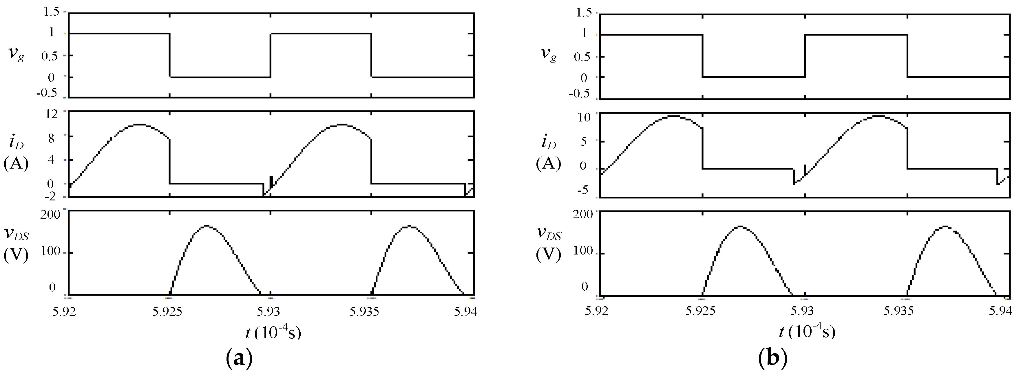
4.1. Foreign Metal Object is Near the Receiver Coil

If the foreign metal object exists near the receiver coil, i.e., along the line l1 as shown in Figure 3, the inductance of the receiver coil will be reduced by ΔL, while the resistance of the receiver coil will be increased by ΔR. The decrement of the receiver coil inductance detunes the receiver side, so that the reflected impedance seen from the transmitter coil becomes
Z r = ( ω M ) 2 R 2 + Δ R j ω Δ L .
Equation (8) can be transformed to
Z r = ( ω M ) 2 ( R 2 + Δ R ) 2 + ( ω Δ L ) 2 ( R 2 + Δ R + j ω Δ L ) .
Clearly, the reactance of the transmitter side will be increased by ΔL2, which can be calculated by
Δ L 2 = Im ( Z r ) ω = ( ω M ) 2 ( R 2 + Δ R ) 2 + ( ω Δ L ) 2 Δ L .
However, the real part of Zr is smaller than its original value, i.e.,
Re ( Z r ) = ( ω M ) 2 ( R 2 + Δ R ) 2 + ( ω Δ L ) 2 ( R 2 + Δ R ) < ( ω M ) 2 R 2 + Δ R < ( ω M ) 2 R 2 = R r .
As a result, the resistance of the transmitter side will be decreased by ΔR2, which can be expressed as
Δ R 2 = R r Re ( Z r ) .
Therefore, the equivalent impedance angle ϕ of the Class-E inverter will increase when the foreign metal object exists near the receiver coil, which is expressed as
φ = arctan ω L 1 1 ω C 1 + Δ L 2 R 1 + R r Δ R 2 > 49.052
In this case, the parasitic diode of the MOSFET will conduct the current i1 in a freewheeling mode, maintaining the ZVS soft-switching condition in the inverter. However, the system efficiency will decrease, since the system deviates from the ideal working conditions [19]. It can be seen from Figure 8 and Figure 9 that as the iron plate moves closer to the receiver coil, the ZVS soft-switching condition will be maintained, while the power transfer and efficiency will decrease monotonically. The cause of this is that if the impedance angle of the resonant tank of the Class-E inverter increases monotonically, then the current in the transmitter coil decreases monotonously, and therefore so does the power transfer. It is noted that the efficiency can be maintained above 85% when the distance d1 is greater than 13 cm.

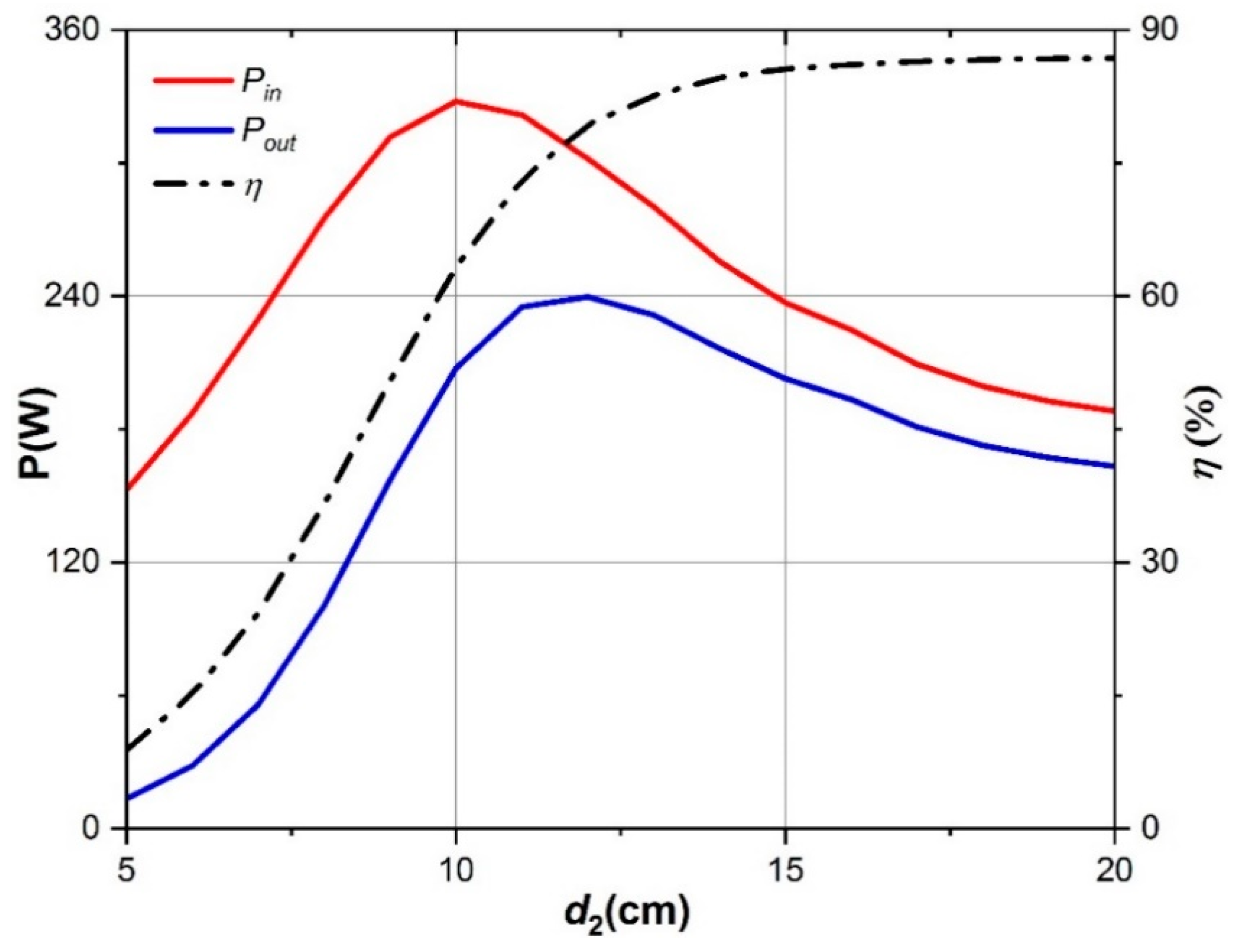
4.2. Foreign Metal Object Is Near the Transmitter Coil

If the foreign metal object exists near the transmitter coil, i.e., along the line l2 as shown in Figure 3, then the coil inductance and resistance will be reduced by ΔL1 and increased by ΔR1 respectively. Therefore, the equivalent load impedance angle ϕ will be decreased according to Equation (14).
φ = arctan ω L 1 1 ω C 1 Δ L 1 R 1 + R r + Δ R 1 < 49.052
The soft-switching conditions will be invalid when the equivalent load impedance angle ϕ is less than 49.052° [19]. In other words, the MOSFET is turned on before the drain-to-source voltage of the MOSFET drops to zero, shown in Figure 10, which causes the switching loss to increase, and the MOSFET may be burnt out at such a high switching frequency.
Moreover, when ϕ becomes smaller as the foreign metal object approaches the transmitter coil, and becomes equal to zero, the transmitter system meets the condition of resonance, and the output power reaches a maximum value according to Equations (4) and (5).
It can be seen from Figure 11 that the resonant tank first approaches the resonant state and then rapidly withdraws from resonance, so that the power transfer rises and then declines dramatically as the iron plate approaches the transmitter coil. Furthermore, the hard switching phenomenon will become more serious, and the efficiency decreases gradually due to the decrement of ϕ. The efficiency from DC supply to load is kept above 85% when d2 is greater than 15 cm.

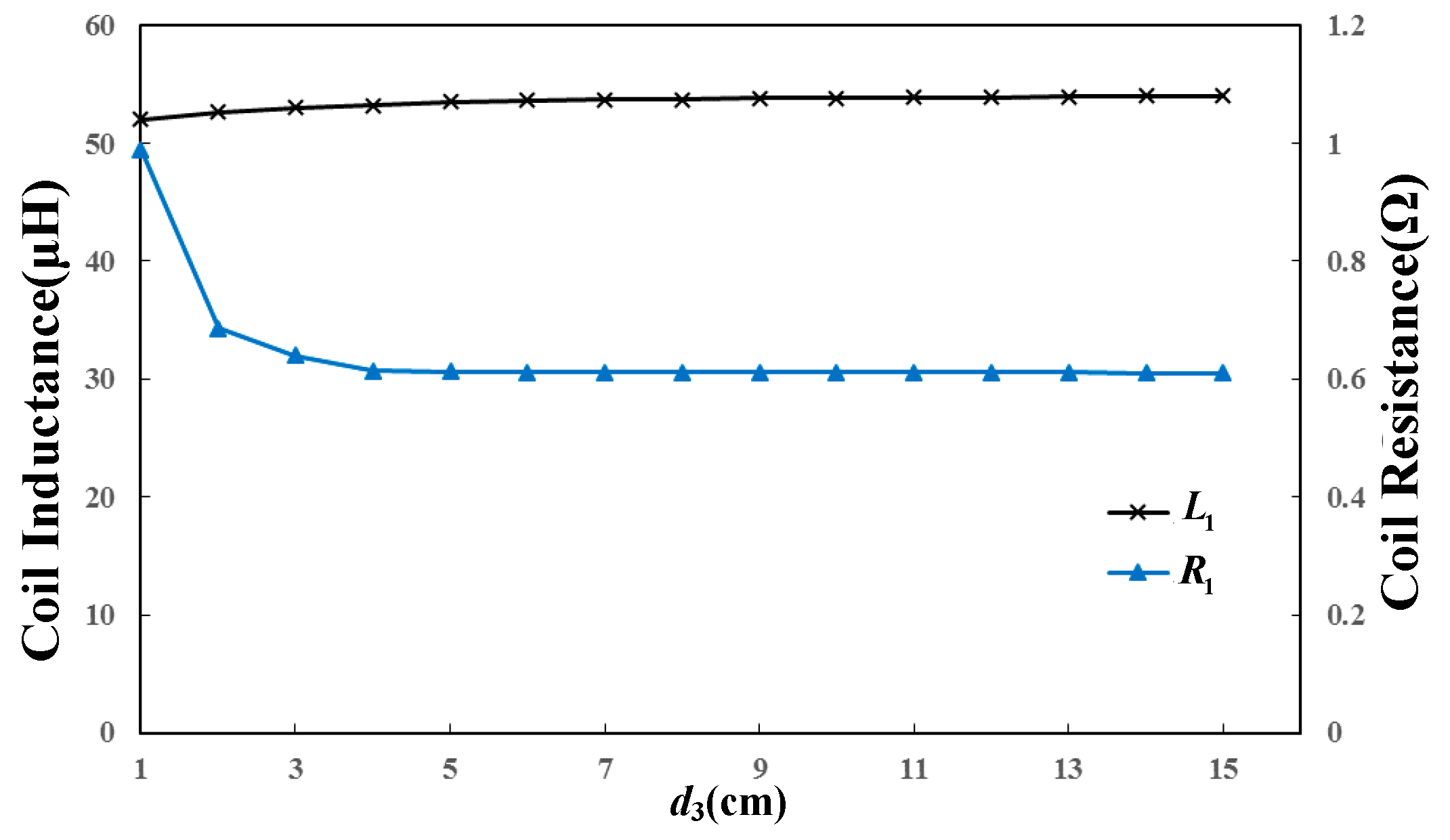
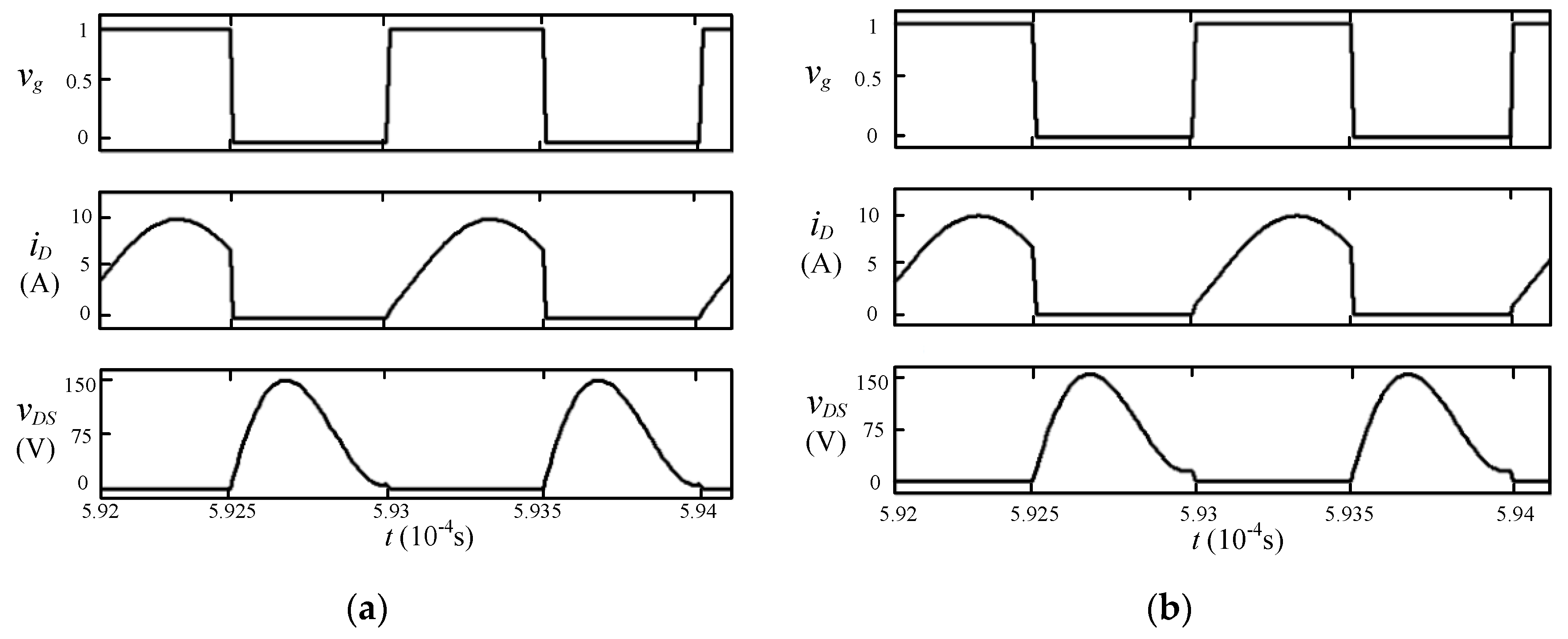
4.3. A Foreign Metal Object Appears at the Outer Side of Two Coils

If the foreign metal object exists at the outer side of the transmitter and receiver coils, i.e., along the line l3 as shown in Figure 3, the parameters of both coils will change simultaneously. Assuming that the metal object has the same effects on the parameters of the two coils, the inductance of both coils will be decreased by ΔL, while the resistance of both coils will be increased by ΔR. According to Equation (9), the formula for the imaginary part of the variation of the equivalent impedance of the transmitter side is
Im ( Δ Z 1 ) = ω Δ L ( ( ω M ) 2 ( R 2 + Δ R ) 2 + ( ω Δ L ) 2 1 ) = ω Δ L ( K 1 1 ) .
However, the formula for the real part is
Re ( Δ Z 1 ) = Δ R + ( ω M ) 2 ( R 2 + Δ R ) 2 + ( ω Δ L ) 2 ( R 2 + Δ R ) ( ω M ) 2 R 2 < Δ R + ( ω M ) 2 R 2 + Δ R ( ω M ) 2 R 2 = Δ R ( 1 ( ω M ) 2 R 2 ( R 2 + Δ R ) ) = Δ R ( 1 K 2 ) .
Therefore, the equivalent load impedance angle ϕ can be calculated as
φ = arctan ω L 1 1 ω C 1 + Im ( Δ Z 1 ) R 1 + R r + Re ( Δ Z 1 ) .
Generally, when the metal object is far from the coils, ΔL and ΔR are relatively small, so K1 in Equation (15) or K2 in Equation (16) degenerates to ( ω M ) 2 / R 2 2 .
If ω M > R 2 and d3 is large enough, then
( ω M ) 2 ( R 2 + Δ R ) 2 + ( ω Δ L ) 2 > 1
( ω M ) 2 R 2 ( R 2 + Δ R ) > 1 .
As a result, Im(ΔZ1) is positive, while Re(ΔZ1) is negative. According to Equation (17), the equivalent load impedance angle is larger than 49.052°, so the ZVS soft-switching condition is maintained.
As the distance d3 becomes smaller and ΔR and ΔL become accordingly larger accordingly, then the inequality signs of Equations (18) and (19) will be reversed. Therefore, Im(ΔZ1) will be negative while Re(ΔZ1) will be positive, so the soft-switching conditions will be invalid. In summary, the validity of soft-switching conditions depends on the distance d3 when ω M > R 2 .
In contrast, if ω M < R 2 , then Im(ΔZ1) will be negative while Re(ΔZ1) will be positive at any distance d3. As a result, the soft-switching conditions will be invalid once the metal object is introduced.
The simulation results are shown in Figure 12 and Figure 13. It is noted that ω M < R 2 based on the parameters listed in Table 2, therefore the soft-switching conditions are invalid when the metal object is introduced. In addition, the hard-switching phenomenon becomes more severer as d3 decreases. Similarly, the efficiency will drop because the system deviates from the ideal working conditions. The transmission efficiency keeps at above 85% and the power transfer keeps around the nominal value when the distance d3 is greater than 10 cm, which implies that the iron plate appearing at the outer side of two coils has a smaller impact on the system.

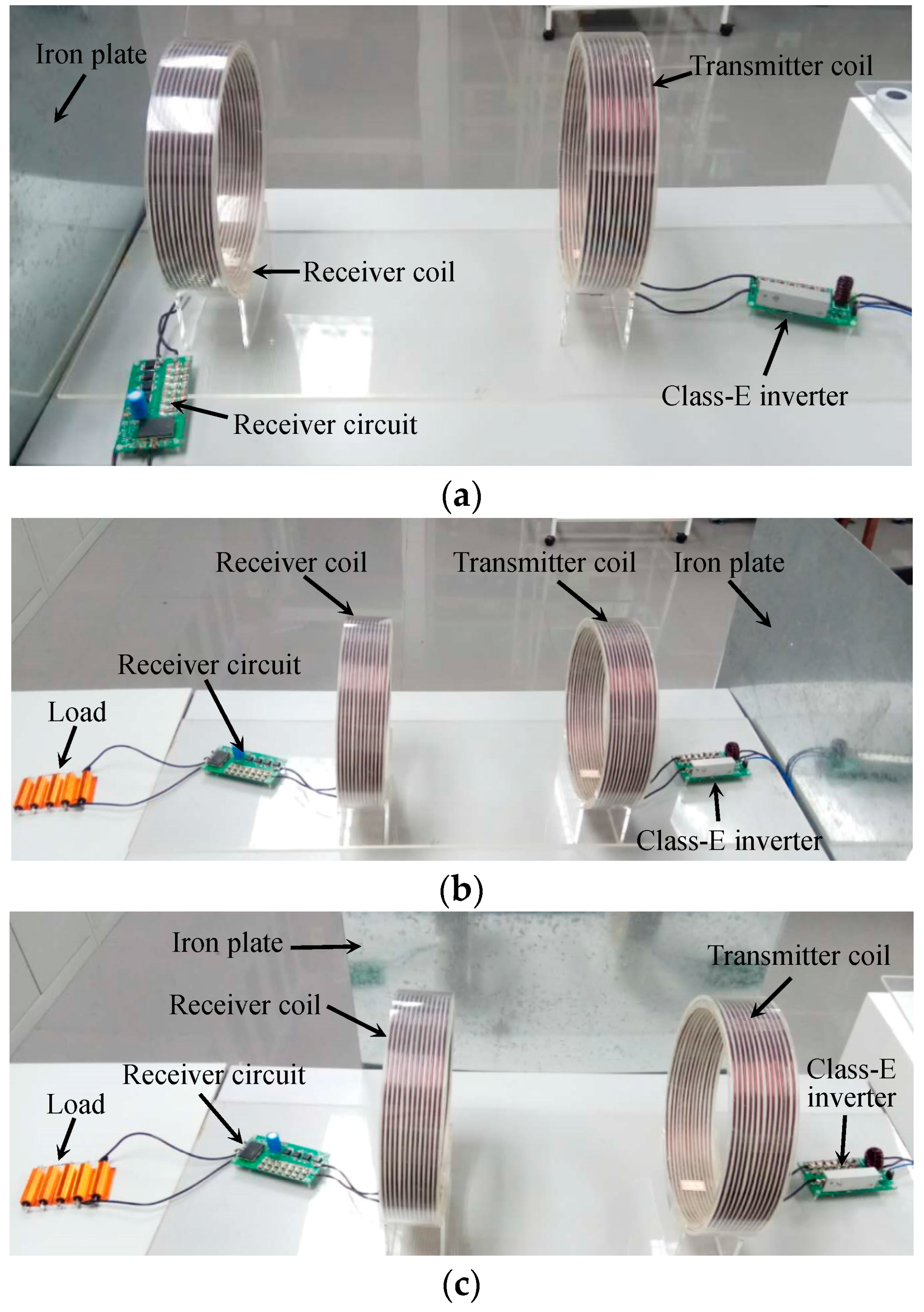
5. Experiment and Analysis
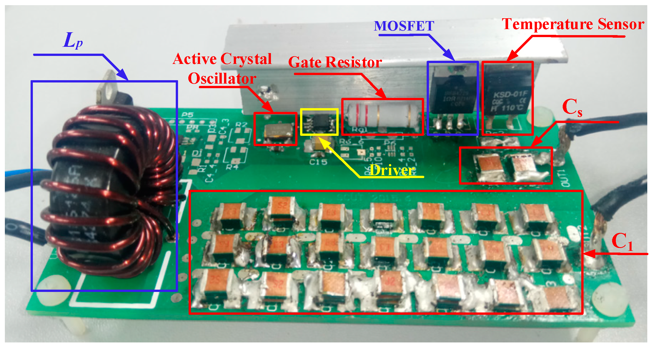
5.1. Prototype

A WPT system with Class-E inverter is built up to verify the qualitative analysis presented in the former sections. The system consists of two identical helix coils with the parameters shown in Table 1. The resistance and inductance of the helix coil are measured using precision impedance analyzer WAYNE KERR 6500B (1J6550B, Wayne Kerr Electronics Inc., West Sussex, UK). The measured results of the coil resistance and inductance are 0.65 Ω and 54.41 μH respectively, which are highly consistent with the simulation results.
The whole system is shown in Figure 14, including the Class-E inverter, transmitter coil, receiver coil, receiver circuit, and the load. The details of the Class-E inverter are shown in Figure 15. According to the analysis in Section 4, the maximum drain to source voltage of the MOSFET is close to 200 V and the maximum drain current is 10.2 A, so the Class-E inverter is fabricated using the IPP200N25N3 power MOSFET from Infineon. An active crystal oscillator is used to generate a stable 1 MHz square wave to the driver FAN3122TMX. A temperature sensor KSD-01FH, which is connected to the enable pin of the driver, is used to protect the MOSFET. The compensation capacitor C1, C2 and shunt capacitor Cs are made up of several mica capacitors combining in series and parallel to mitigate the voltage and current stress, and their capacitance value are consistent with those in Table 2. With these parameters design, the Class-E inverter works ideally at ZVS and ZDS soft-switching conditions.
The position demonstrations of the iron plate placed along the line l1, l2 and l3 are shown in Figure 14a–c, respectively.
All the experimental waveforms and values of voltage and current are measured by the oscilloscope DPO-2024B. The input power is obtained by multiplying the input voltage by the cycle-mean of the input current, and the output power is obtained by multiplying the load resistance by the square of the cycle-RMS of the output current.

5.2. Experimental Result and Analysis

In order to demonstrate the break-down in soft-switching conditions, the input DC voltage is reduced to protect the WPT system. Experimental waveforms of driver signal vGS, transmitter current i1, and drain-to-source voltage vDS when the iron plate is placed along the line l1, l2, and l3 are shown in Figure 16, Figure 17 and Figure 18, respectively.
(1)
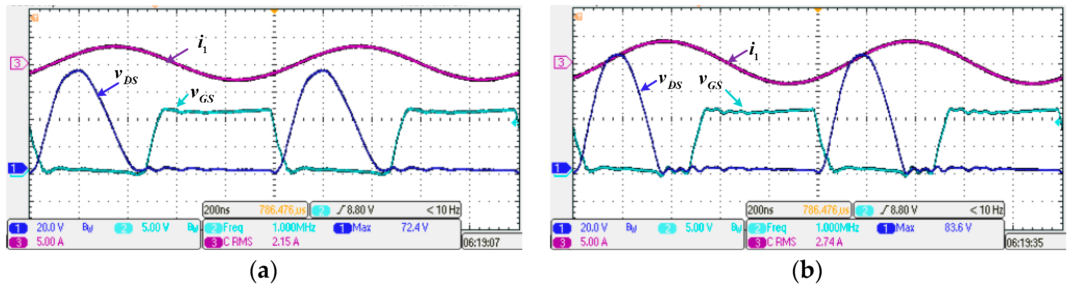
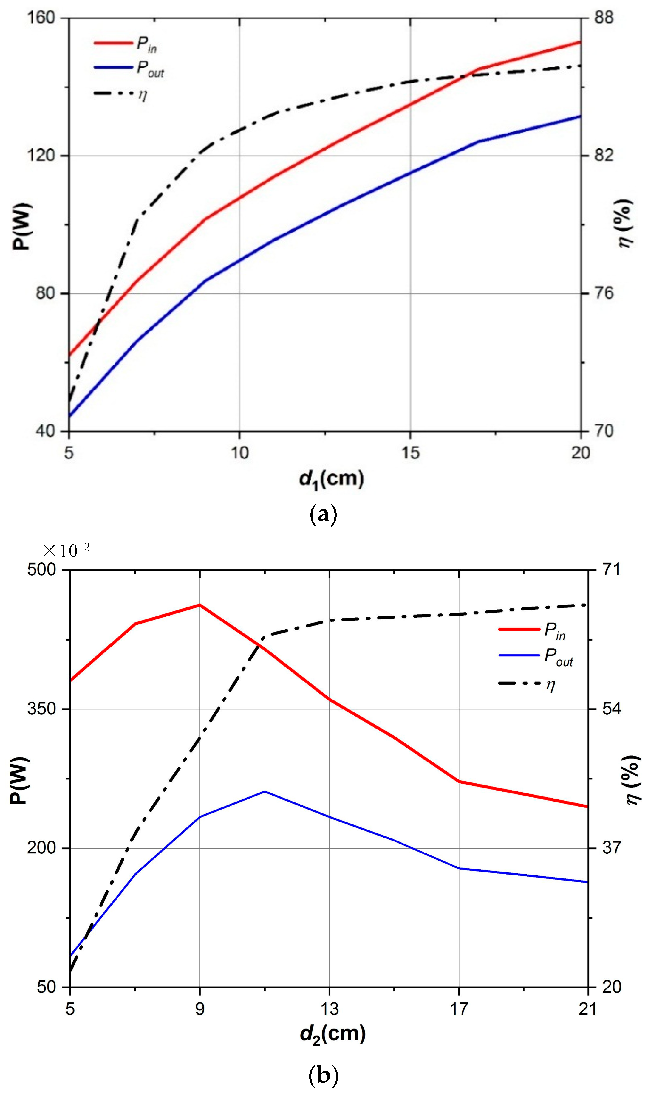
When the iron plate is placed along the line l1, the ZVS soft-switching condition could be maintained. It can be seen from Figure 16 that the interval, after vDS decreases to zero and before the power MOSFET turns on, gets larger as the iron plate approaches the receiver coil. However, it will increase the voltage stress of the power MOSFET and reduce the output power as the iron plate detunes the resonant network of the receiver system.
(2)
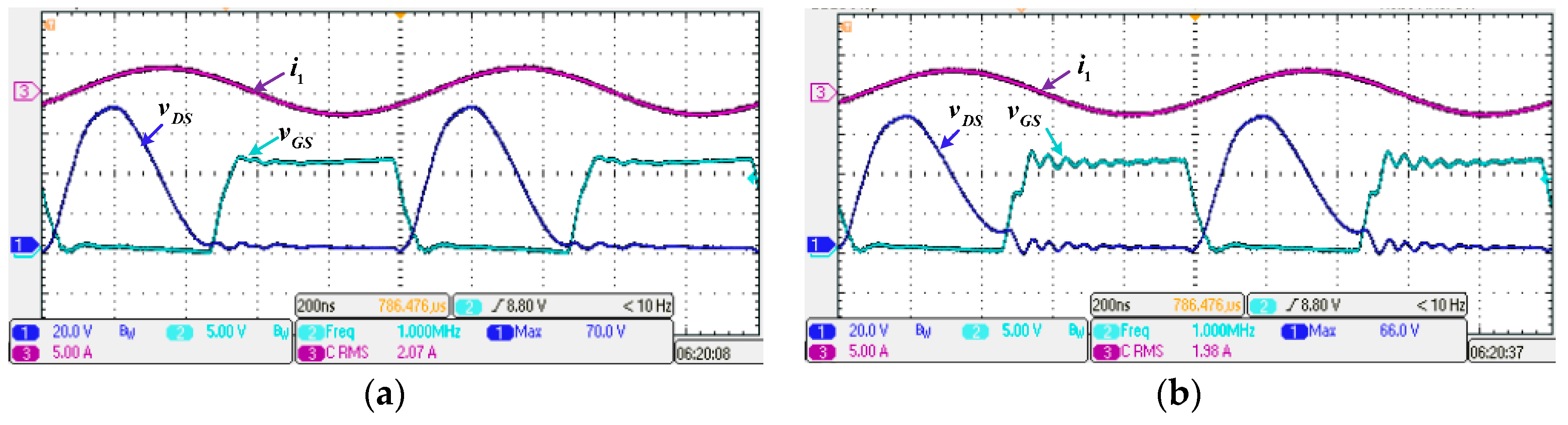
On contrast, when the iron plate is placed along the line l2, it is obvious from Figure 17 that the soft-switching conditions will be invalid immediately as long as the iron plate is involved. Also, the hard-switching phenomenon will become severer, while the transmitter current I1 will increase to transfer more power. However, it will jeopardize the system and cause the power MOSFET or the compensation capacitors to be burnt out.
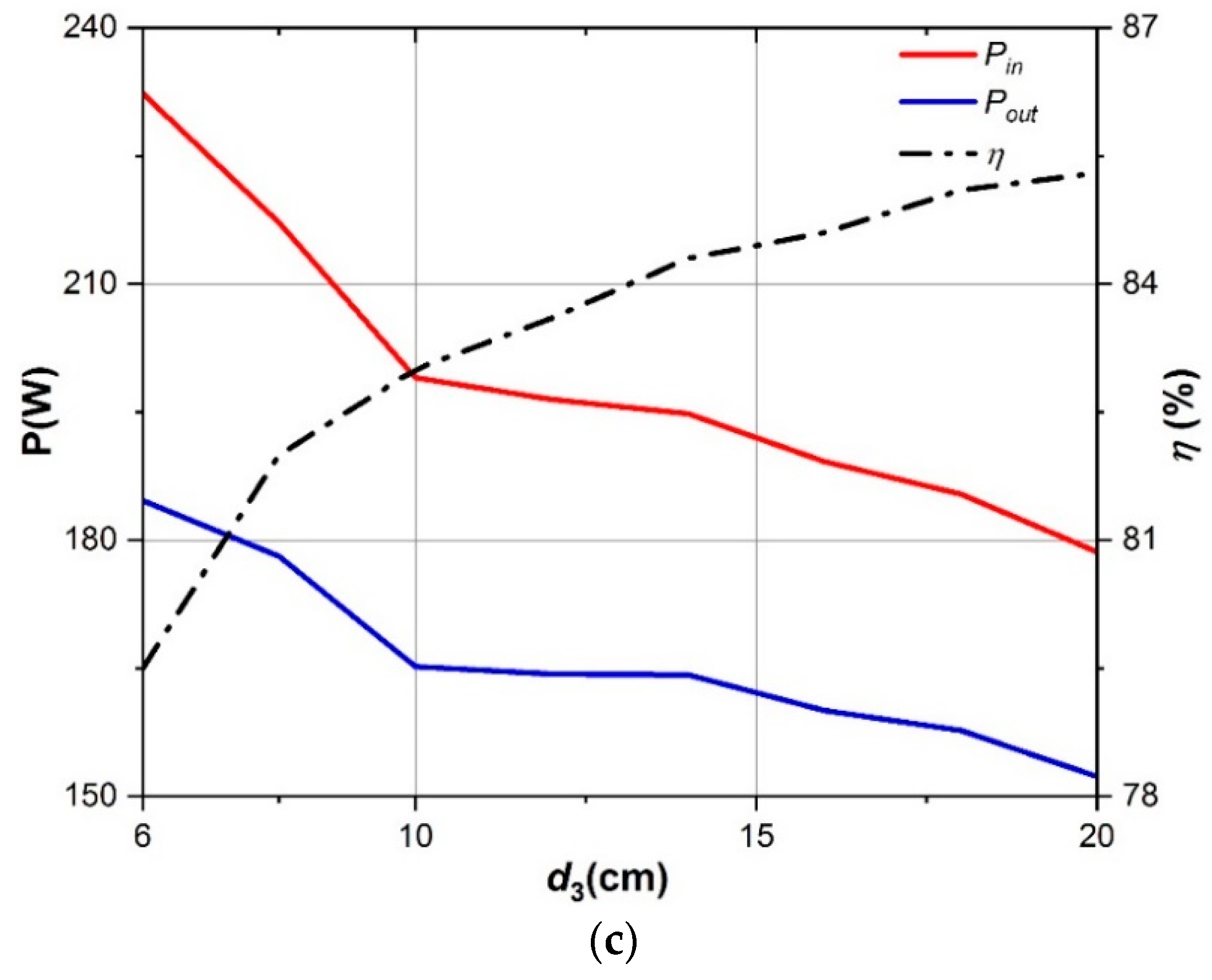
(3)
It is noted that, when the iron plate is placed along the line l3, the Class-E inverter is slightly hard-switched when d3 equals to 15 cm. It confirms that the iron plate appearing at the outer side of two coils has a smaller impact on the system, although the hard-switching phenomenon will become obvious when d3 reaches 5 cm.
The experimental results of three kinds of situation are consistent with the analyses and simulations presented in Section 4.
The transfer power and efficiency versus the distance d1, d2, and d3 are shown in Figure 19a–c, respectively. It is noted that the input DC voltage should be reduced to protect the WPT system when the metal plate appears along the line l2. It is obvious that the experimental results are consistent with the simulation results presented in the former section. The transfer power decreases monotonously as the metal plate approaches the receiver coil gradually, while the transfer power increases first and then decreases as the metal plate approaches the transmitter coil. On contrast, the transfer power increases gradually as the distance d3 gets smaller. It is noted that the iron plate will jeopardize the transfer efficiency regardless of its position.
The total experimental power losses include the power losses of the coil resistance R1 and R2, the parasitic resistance of the capacitor C1 and C2, the parasitic resistance of the choke inductor LP, the conduction loss of the MOSFET, and so on. Therefore, the power loss of each component can be estimated according to the components’ datasheets, and the power loss distribution in the absence of the foreign metal object is shown in Figure 20. It is obvious that R1 has a major contribution to the power losses, and reducing the coil resistance helps to improve the efficiency. Unfortunately, when the metal plate is close to the transmitter coil, R1 will increase, resulting in a large increment in the power losses. In addition, when the soft-switching conditions are broken down, the power loss of the MOSFET will increase significantly, even causing the MOSFET to be burnt out.
In fact, when the metal object appears along the line l2, it has the worst impacts on the system, such as destroying the soft-switching conditions and causing an unexpected large current I1. Therefore, the capacitance of the compensation capacitor C1 could be increased to compensate for the effects of the metal object, but the efficiency and the transfer power will be decrease slightly. In practice, the increment of the capacitance depends on the reduction of the inductance caused by the metal object. After changing the capacitance of C1 to 487.2 pF, the waveforms of vGS and vDS are presented in Figure 21, where d2 equals to 10 cm. Comparing with Figure 17b, the ZVS soft-switching condition could be maintained.

6. Conclusions

In this paper, the influences of different metal materials on coil parameters at different frequencies and different positions have been analyzed, and the influence principles and rules of foreign metal object on soft-switching conditions of the Class-E inverter and power transfer of the WPT system have been developed as follows:
When a foreign metal object is placed at the receiver side, the soft-switching conditions can be maintained, but the power transfer is less than the nominal value and decreases monotonically as the foreign metal object approaches the receiver coil.
When the foreign metal object is placed near the transmitter coil, the soft-switching conditions will be invalid. As the foreign metal object approaches the coil gradually, the power transfer of the WPT system will increase until reaching the maximum value, where the transmitter system works at resonant state, and then decrease dramatically.
When the foreign metal object appears at the outer side of the two coils, the soft-switching conditions depend on the distance between the foreign metal object and the coils when ω M > R 2 , while the soft-switching conditions will be invalid when ω M < R 2 .
The experimental results are highly consistent with the principle analyses and the simulations. In addition, the method to mitigate the influence of foreign metal object on soft-switching conditions is also presented.

Author Contributions

W.X. provided the idea, designed the prototype and revised the article. R.S. contributed the analysis, performed the experiments and wrote the article; T.L. implemented the simulations; B.Z., D.Q. and Y.C. guided and revised the paper.

Funding

This project was supported by the Key Program of National Natural Science Foundation of China (Grant No. 51437005), Natural Science Foundation of Guangdong Province, China (Grant No. 2016A030313515) and the Fundamental Research Funds for the Central Universities, China (Grant No. 201522082).

Conflicts of Interest

The authors declare no conflict of interest.

References

  1. Kuyvenhoven, N.; Dean, C.; Melton, J.; Schwannecke, J.; Umenei, A.E. Development of a foreign object detection and analysis method for wireless power systems. In Proceedings of the 2011 IEEE Symposium on Product Compliance Engineering Proceedings, San Diego, CA, USA, 10–12 October 2011. [Google Scholar]
  2. Fukuda, S.; Nakano, H.; Murayama, Y.; Murakami, T.; Kozakai, O.; Fujimaki, K. A novel metal detector using the quality factor of the secondary coil for wireless power transfer systems. In Proceedings of the 2012 IEEE MTT-S International Microwave Workshop Series on Innovative Wireless Power Transmission: Technologies, Systems, and Applications, Kyoto, Japan, 10–11 May 2012. [Google Scholar]
  3. Wang, Y.C.; Chiang, C.W. Foreign Metal Detection by Coil Impedance for EV Wireless Charging System. In Proceedings of the EVS28 International Electric Vehicle Symposium Exhibition, KINTEX, Goyang, Korea, 3–6 May 2015. [Google Scholar]
  4. Mi, C.C.; Buja, G.; Choi, S.Y.; Rim, C.T. Modern Advances in Wireless Power Transfer Systems for Roadway Powered Electric Vehicles. IEEE Trans. Ind. Electron. 2016, 63, 6533–6545. [Google Scholar] [CrossRef]
  5. Liu, G.; Mrad, N.; Xiao, G.; Li, Z.; Ban, D. Metallic Environmental Effect on RF-Based Energy Transmission. IEEE Antennas Wirel. Propag. Lett. 2012, 11, 925–928. [Google Scholar] [CrossRef]
  6. Oodachi, N.; Ogawa, K.; Obayashi, S.; Shoki, H. Wireless power transfer system minimizing an influence of a desk. In Proceedings of the 2012 IEEE MTT-S International Microwave Workshop Series on Innovative Wireless Power Transmission: Technologies, Systems, and Applications, Kyoto, Japan, 10–11 May 2012. [Google Scholar]
  7. Jiang, H.; Brazis, P.; Tabaddor, M.; Bablo, J. Safety considerations of wireless charger for electric vehicles—A review paper. In Proceedings of the 2012 IEEE Symposium on Product Compliance Engineering Proceedings, Portland, OR, USA, 5–7 November 2012. [Google Scholar]
  8. Pávó, J.; Badics, Z.; Bilicz, S.; Gyimóthy, S. Efficient Perturbation Method for Computing Two-Port Parameter Changes Due to Foreign Objects for WPT Systems. IEEE Trans. Magn. 2017, 54, 1–4. [Google Scholar] [CrossRef]
  9. Zhang, P.; Yang, Q.; Zhang, X.; Li, Y.; Li, Y. Comparative Study of Metal Obstacle Variations in Disturbing Wireless Power Transmission System. IEEE Trans. Magn. 2017, 53, 1–4. [Google Scholar] [CrossRef]
  10. Krishnan, S.; Bhuyan, S.; Kyaw, O.; Kumar, V.P.; Wenjiang, W. Effect of proximal metallic objects on the performance of wireless charging systems for electric vehicles. In Proceedings of the 2012 IEEE International Symposium on Radio-Frequency Integration Technology (RFIT), Singapore, 21–23 November 2012. [Google Scholar]
  11. Wiengarten, R.; Reising, V.; Vosshagen, T.; Turki, F. About the heating of foreign metallic objects in magnetic field of wireless power transfer by cars. In Proceedings of the PCIM Europe 2015—International Exhibition and Conference for Power Electronics, Intelligent Motion, Renewable Energy and Energy Management, Nuremberg, Germany, 19–20 May 2015. [Google Scholar]
  12. Tan, L.; Li, J.; Chen, C.; Yan, C.; Guo, J.; Huang, X. Analysis and performance improvement of WPT systems in the environment of single non-ferromagnetic metal plates. Energies 2016, 9, 576. [Google Scholar] [CrossRef]
  13. Jeong, N.S.; Carobolante, F. Enabling wireless power transfer though a metal encased handheld device. In Proceedings of the Wireless Power Transfer Conference, Aveiro, Portugal, 5–6 May 2016. [Google Scholar]
  14. Jeong, S.Y.; Kwak, H.G.; Jang, G.C.; Choi, S.Y.; Rim, C.T. Dual-purpose Non-overlapping Coil Sets as Metal Object and Vehicle Position Detections for Wireless Stationary EV Chargers. IEEE Trans. Power Electron. 2017, 33, 7387–7397. [Google Scholar] [CrossRef]
  15. Jeong, S.Y.; Thai, V.X.; Park, J.H.; Rim, C.T. Self-inductance Based Metal Object Detection with Mistuned Resonant Circuits and Nullifying Induced Voltage for Wireless EV Chargers. IEEE Trans. Power Electron. 2018, 1. [Google Scholar] [CrossRef]
  16. Low, Z.N.; Casanova, J.J.; Maier, P.H.; Taylor, J.A.; Chinga, R.A.; Lin, J. Method of Load/Fault Detection for Loosely Coupled Planar Wireless Power Transfer System with Power Delivery Tracking. IEEE Trans. Ind. Electron. 2010, 57, 1478–1486. [Google Scholar] [CrossRef]
  17. Raab, F.H. Idealized operation of the class E tuned power amplifier. IEEE Trans. Circ. Syst. 1977, 24, 725–735. [Google Scholar] [CrossRef]
  18. Celozzi, S.; Araneo, R.; Lovat, G. Electromagnetic Shielding, 1st ed.; John Wiley & Sons: Hoboken, NJ, USA, 2008; pp. 21–33. [Google Scholar]
  19. Raab, F.H. Effects of circuit variations on the class E tuned power amplifier. IEEE J. Solid-State Circ. 1978, 13, 239–247. [Google Scholar] [CrossRef]
Figure 1. Schematic diagram of Class-E inverter used in wireless power transfer (WPT) system.
Energies 11 01926 g001
Figure 2. Zero voltage switching (ZVS) and zero derivative switching (ZDS) soft-switching waveforms of Class-E inverter.
Energies 11 01926 g002
Figure 3. Structure of the helix coils and positions of the metal plate.
Energies 11 01926 g003
Figure 4. Helix coil parameters versus frequency with or without metal plate. (a) Inductance; (b) mutual inductance; (c) resistance.
Energies 11 01926 g004aEnergies 11 01926 g004b
Figure 5. Magnetic field map of helix coil. (a) Without metal plate; (b) with metal plate.
Energies 11 01926 g005
Figure 6. Inductance and resistance of the coil versus the distance when the iron metal object is placed along the line l1 or l2.
Energies 11 01926 g006
Figure 7. Inductance and resistance of the coil versus the distance when the iron metal object is placed along the line l3.
Energies 11 01926 g007
Figure 8. Switching states with various distance between the receiver coil and iron plate. (a) d1 = 20 cm; (b) d1 = 15 cm; (c) d1 = 10 cm; (d) d1 = 5 cm.
Energies 11 01926 g008aEnergies 11 01926 g008b
Figure 9. Power transfer and efficiency versus the distance d1.
Energies 11 01926 g009
Figure 10. Switching states with various distance between the transmitter coil and iron plate. (a) d2 = 20 cm; (b) d2 = 15 cm; (c) d2 = 10 cm; (d) d2 = 5 cm.
Energies 11 01926 g010
Figure 11. Power transfer and efficiency versus the distance d2.
Energies 11 01926 g011
Figure 12. Switching states with various distance between the coils and iron plate. (a) d3 = 15 cm; (b) d3 = 5 cm.
Energies 11 01926 g012
Figure 13. Power transfer and efficiency versus the distance d3.
Energies 11 01926 g013
Figure 14. Experimental prototype of WPT system and demonstration of different positions of the iron plate. (a) At the receiver side; (b) at the transmitter side; (c) at the outer side of the two coils.
Energies 11 01926 g014
Figure 15. Experimental prototype of the Class-E inverter.
Energies 11 01926 g015
Figure 16. Waveforms of driver signal vGS, transmitter current i1, and drain-to-source voltage vDS, when iron plate at line l1. (a) d1 = 15 cm; (b) d1 = 5 cm.
Energies 11 01926 g016
Figure 17. Waveforms of driver signal vGS, transmitter current i1, and drain-to-source voltage vDS, when iron plate at line l2. (a) d2 = 15 cm; (b) d2 = 10 cm.
Energies 11 01926 g017
Figure 18. Waveforms of driver signal vGS, transmitter current i1, and drain-to-source voltage vDS, when iron plate at line l3. (a) d3 = 15 cm; (b) d3 = 5 cm.
Energies 11 01926 g018
Figure 19. Power transfer and efficiency versus the distance when iron plate is placed along (a) line l1; (b) line l2; and (c) line l3.
Energies 11 01926 g019aEnergies 11 01926 g019b
Figure 20. Percentage of the power losses caused by different components.
Energies 11 01926 g020
Figure 21. Waveforms of vGS and vDS, when iron plate at line l2 and d2 = 10 cm, after changing the compensation capacitance C1.
Energies 11 01926 g021
Table 1. Parameters of helix coils and metal plate.
SymbolParameterValue
L1, L2Coil inductance54.47 μH
R1, R2Coil resistance0.61 Ω
MMutual inductance1.58 μH
DCoil diameter25 cm
dDiameter of coil wire2.5 mm
pPitch of helix coil2 mm
hHeight of helix coil52 mm
NCoil turns12
DbDistance between coils26 cm
rRadius of metal plate15 cm
tThickness of metal plate2 cm
Table 2. Parameters of the WPT system with Class-E inverter.
SymbolParameterValue
VDCInput DC voltage45 V
RLLoad resistor14.3 Ω
LpInput choke inductor81 μH
CsShunt capacitor4.1 nF
C1Transmitter compensation capacitor478.6 pF
C2Receiver compensation capacitor467 pF
fSwitching frequency1 MHz
f2Resonant frequency at receiver side1 MHz

