Increase in Robustness against Effects of Coil Misalignment on Electrical Parameters Using Magnetic Material Layer in Planar Coils of Wireless Power Transfer Transformer


Abstract
:1. Introduction
2. Theoretical Approach
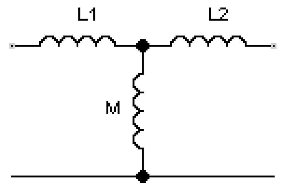
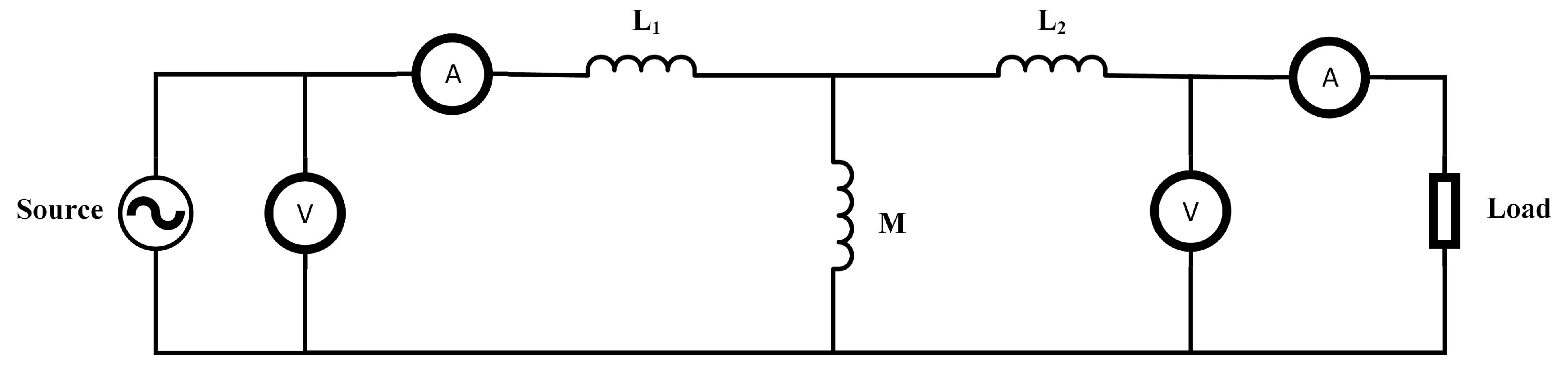
2.1. Electrical Analysis
2.2. Magnetic Analysis
3. Methodology
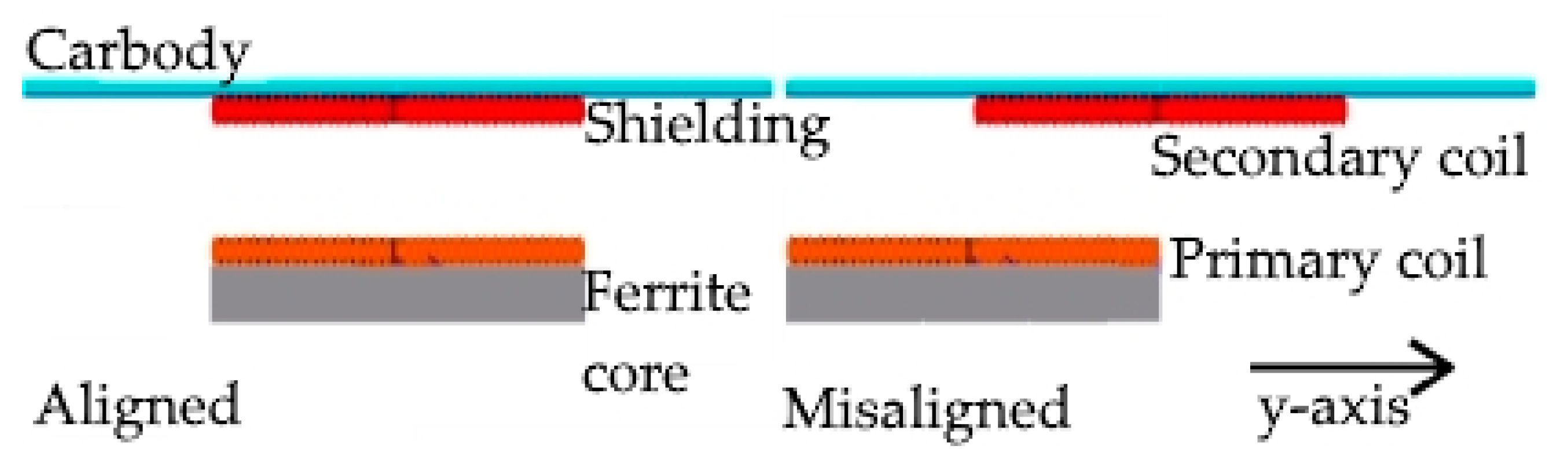
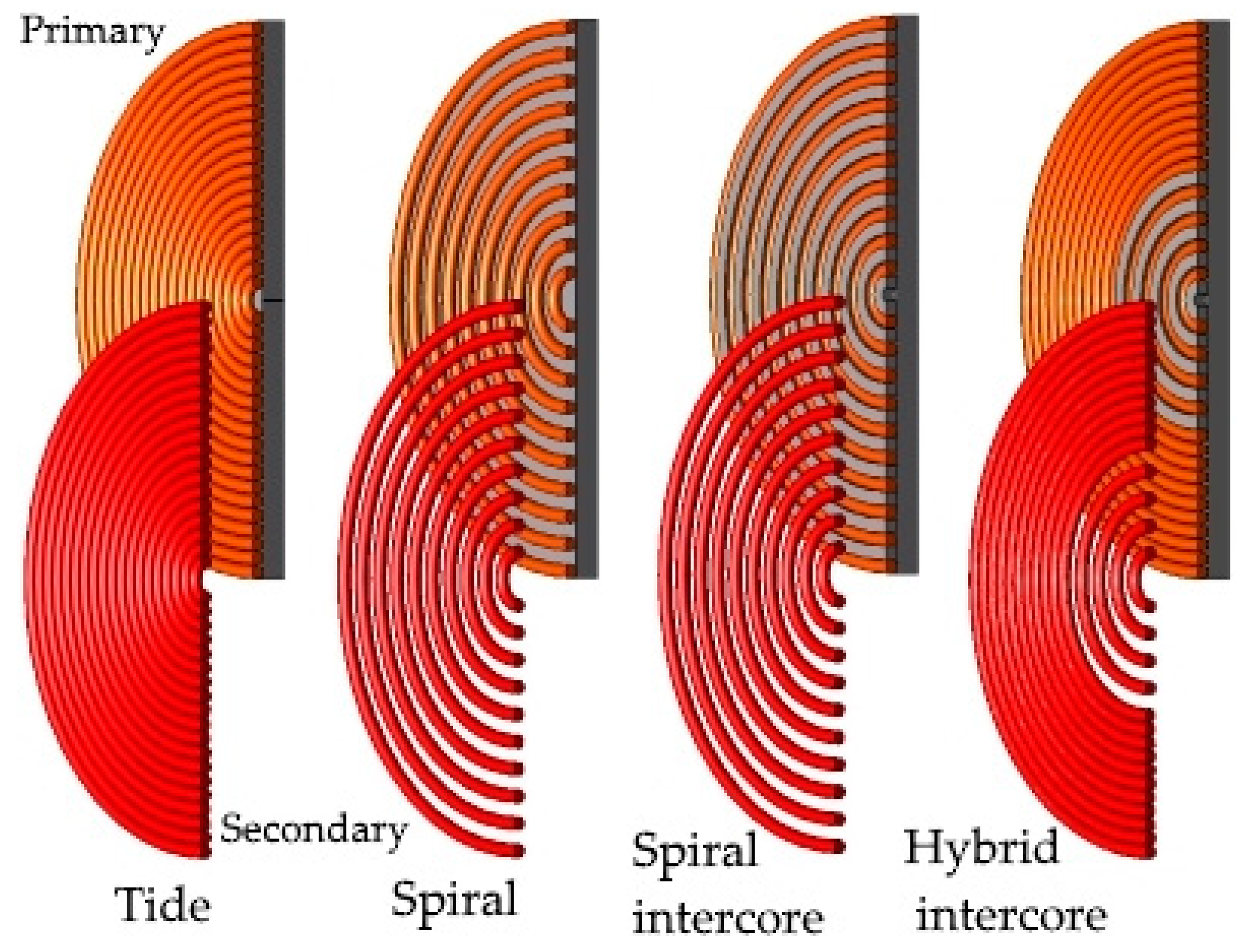
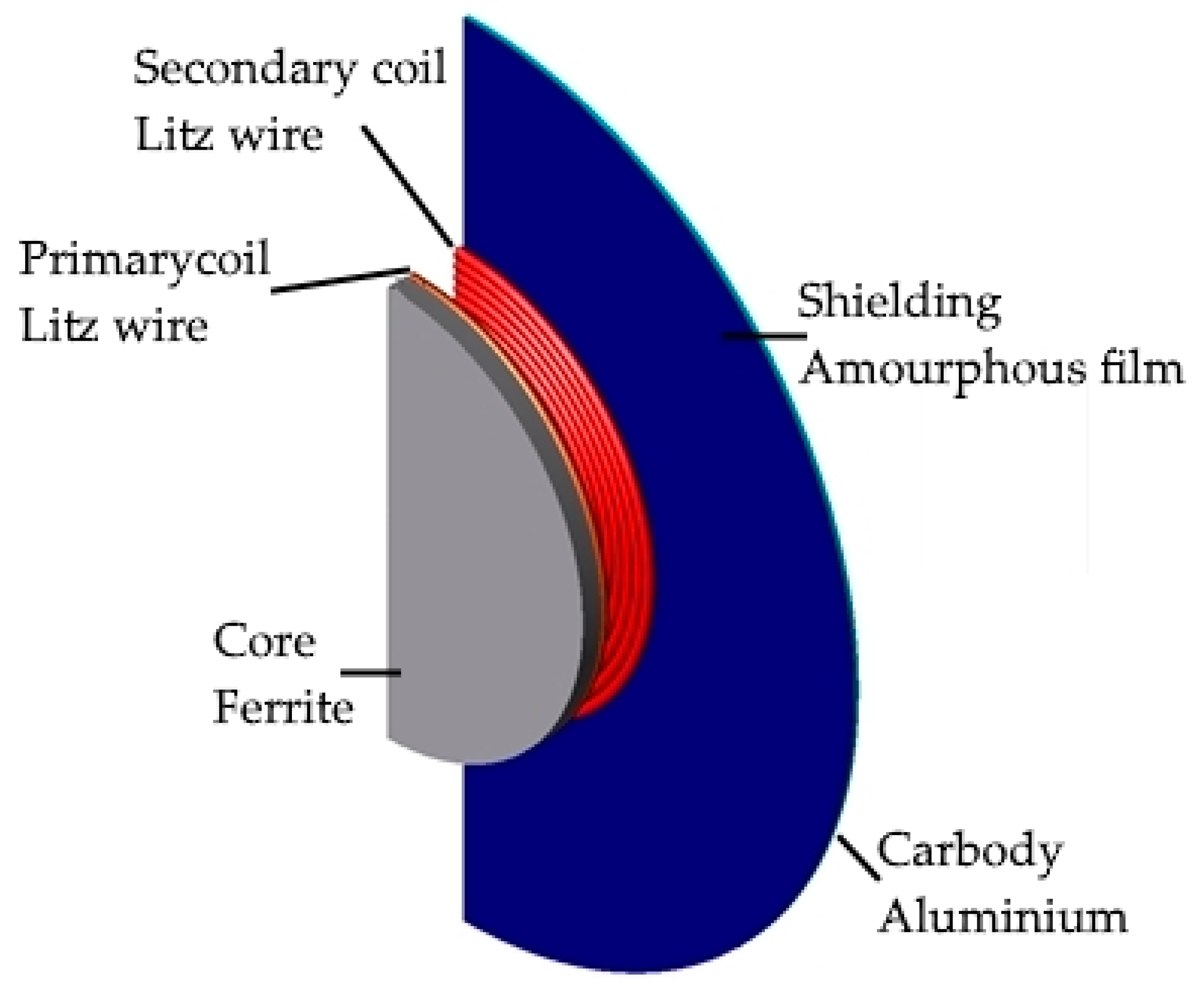
3.1. Modeling
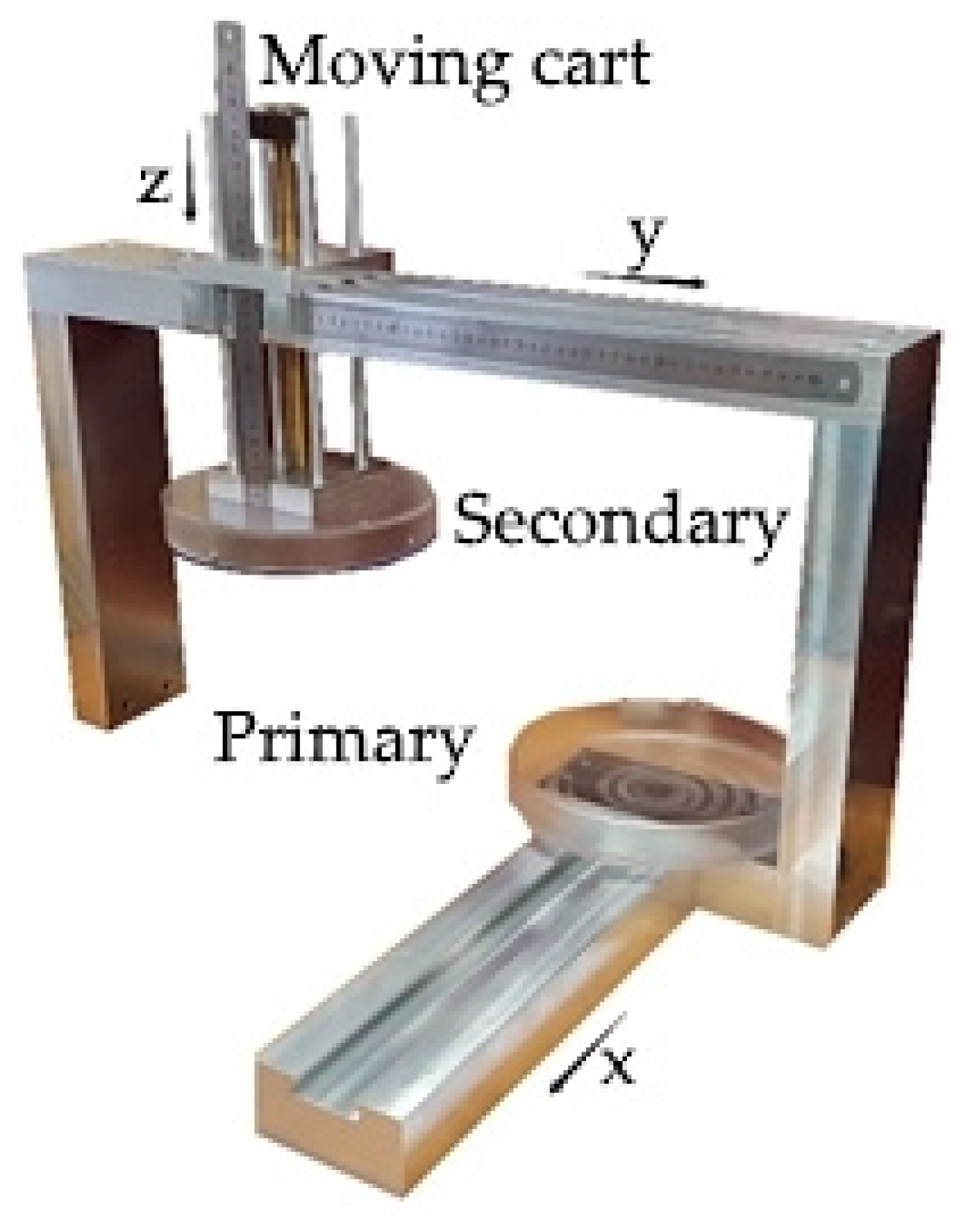
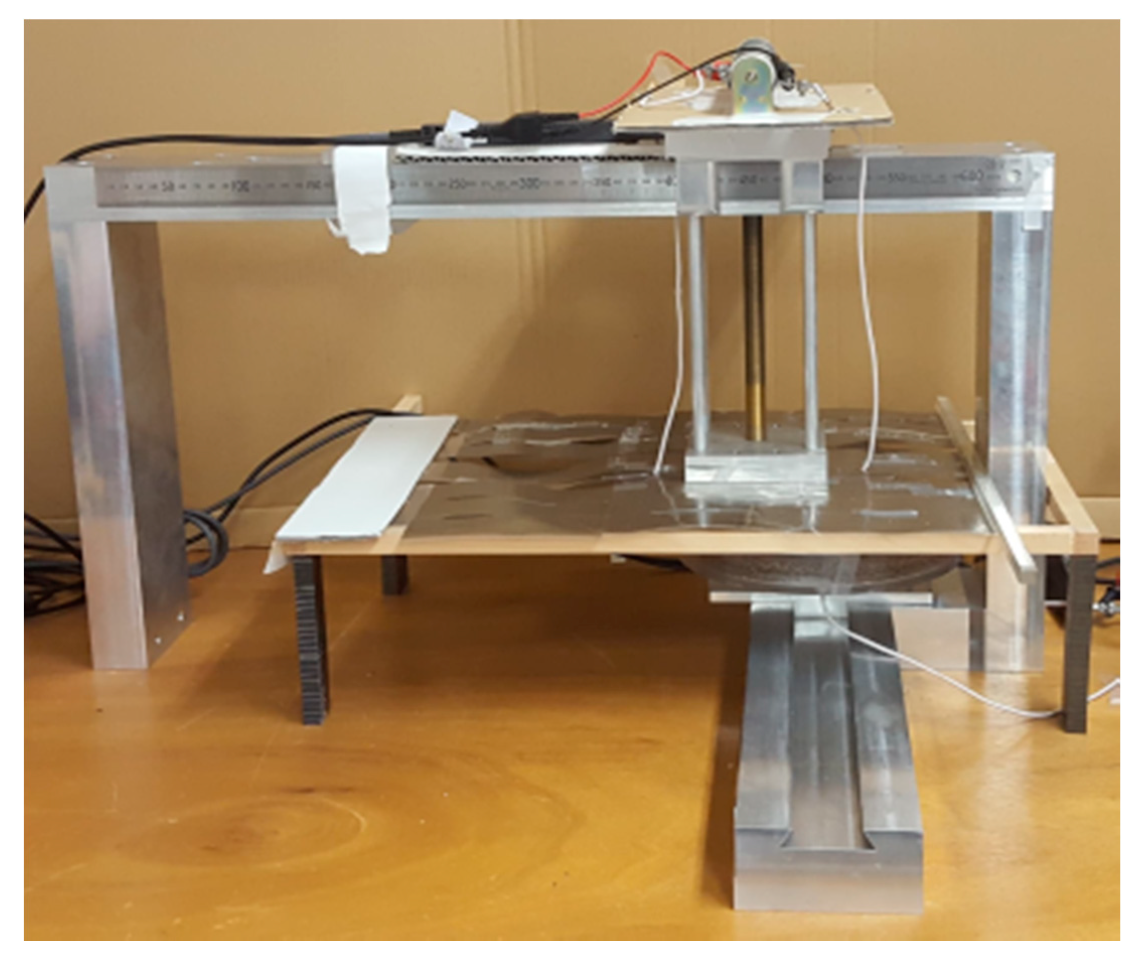
3.2. Prototype Construction
4. Simulation
5. Measurements
6. Results
6.1. Simulation Results
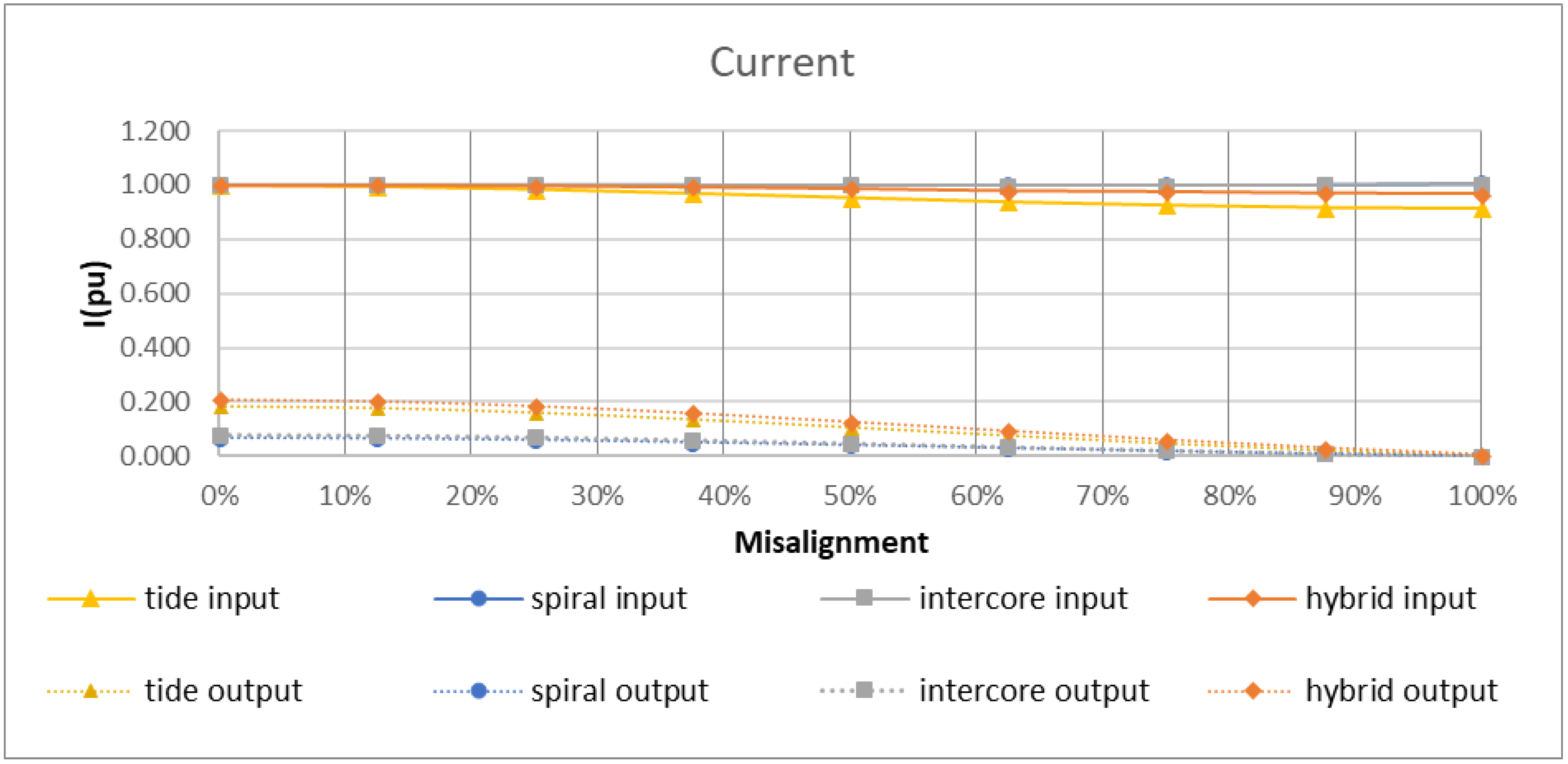
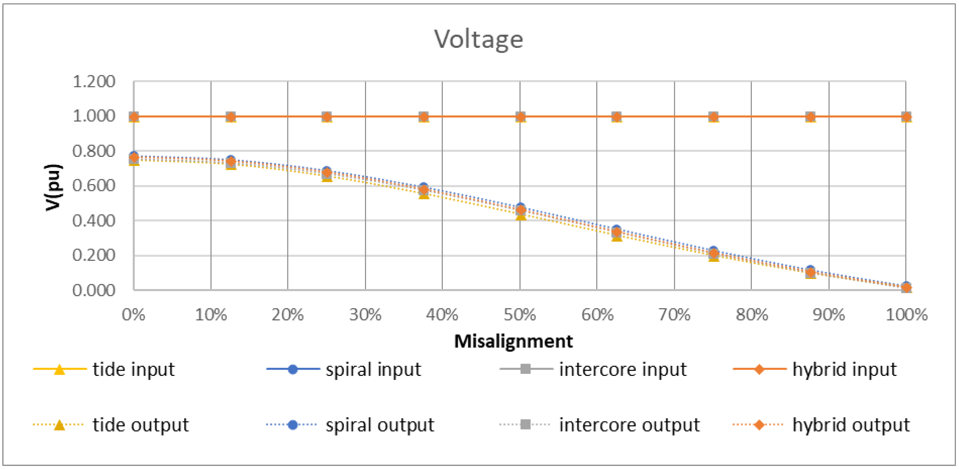
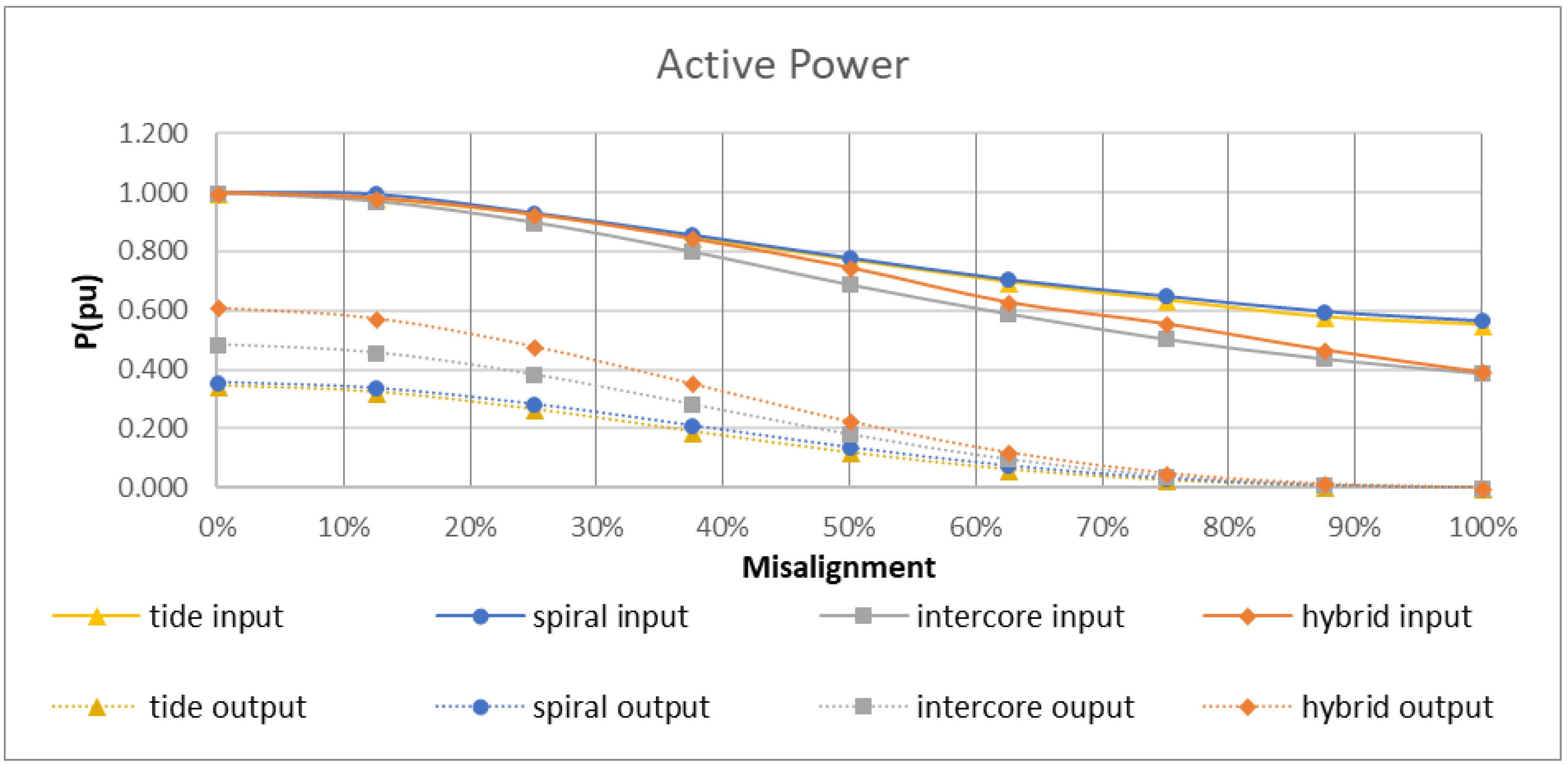
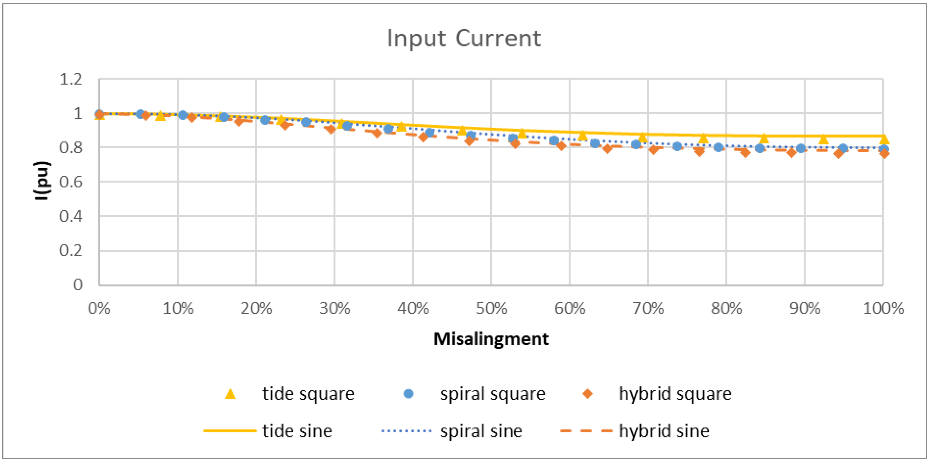
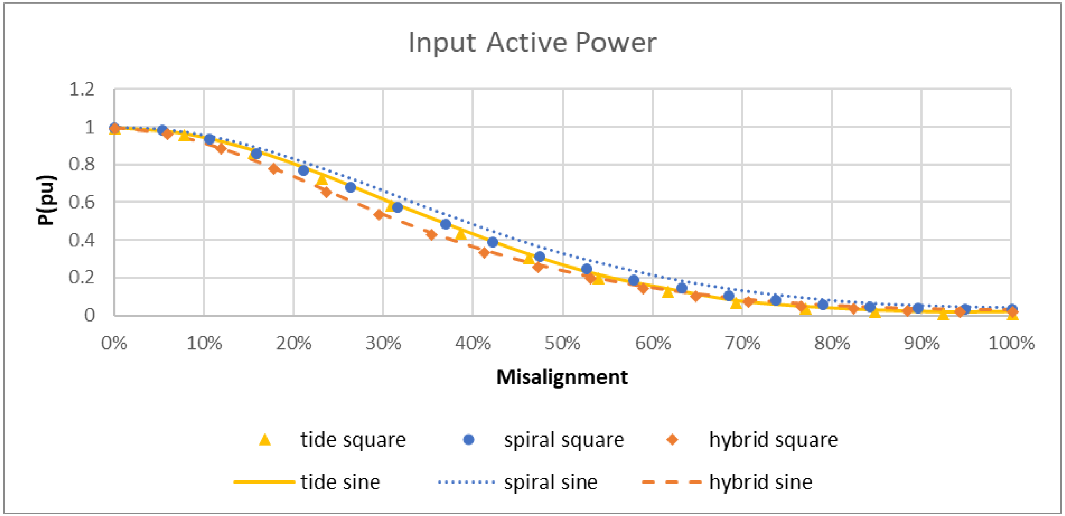
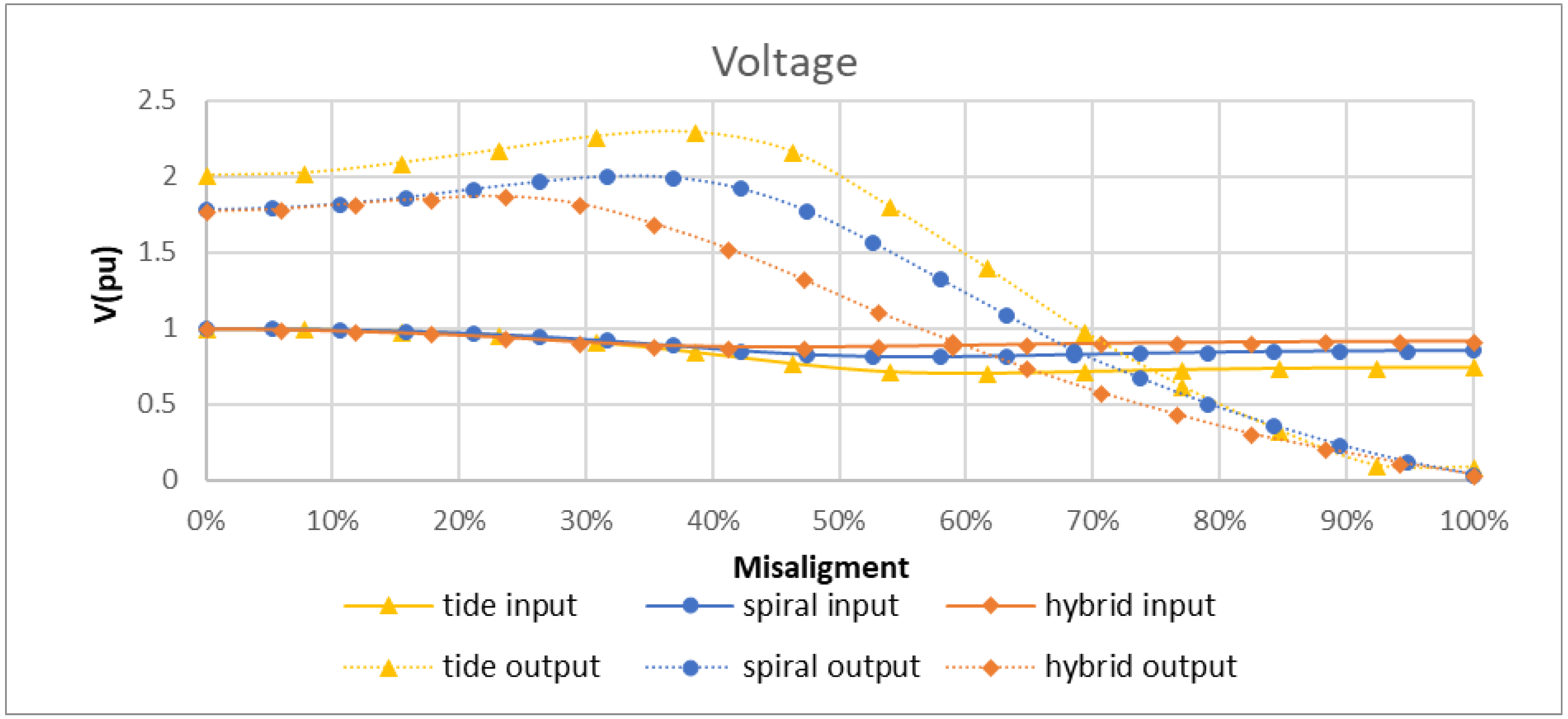
6.1.1. Graphs
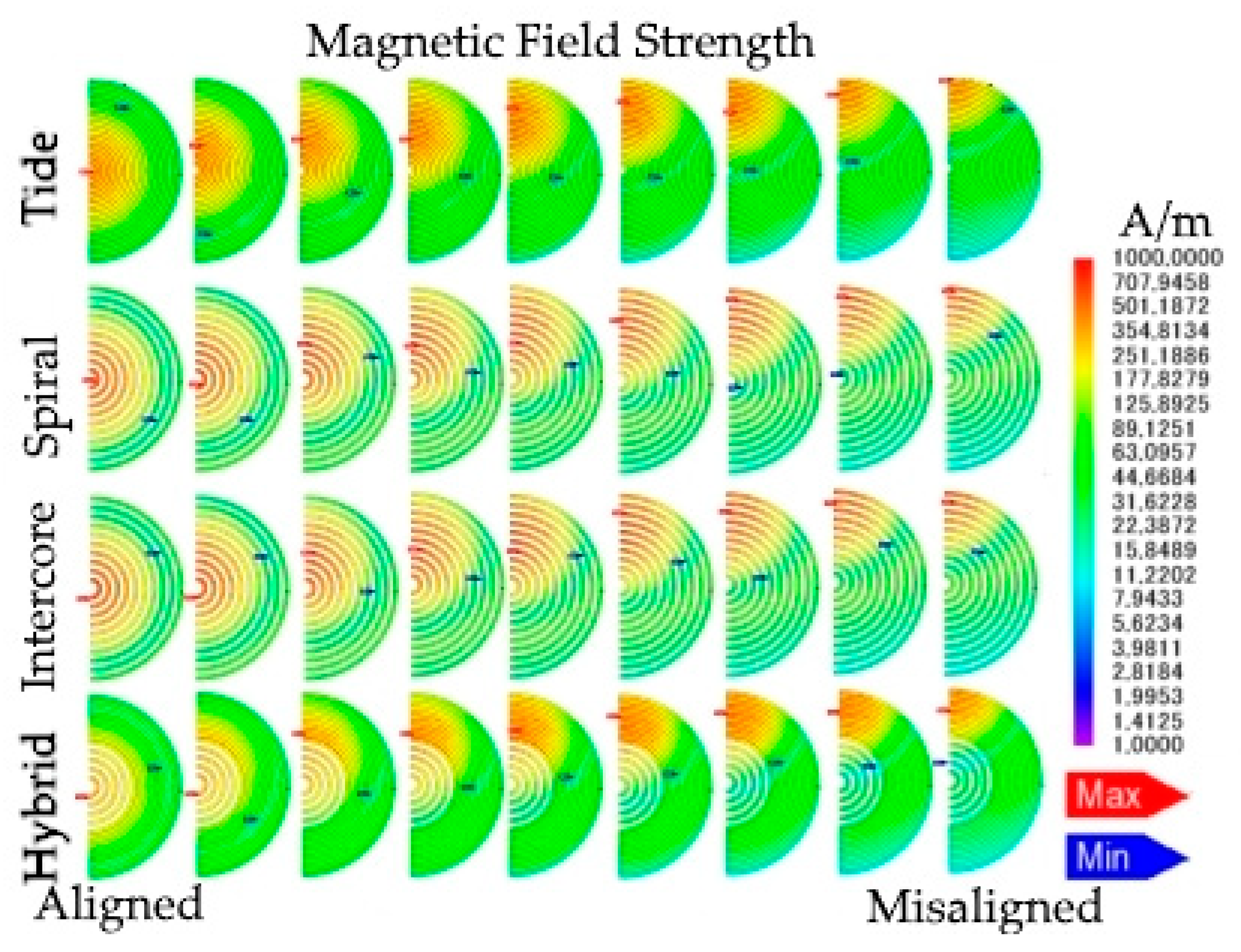
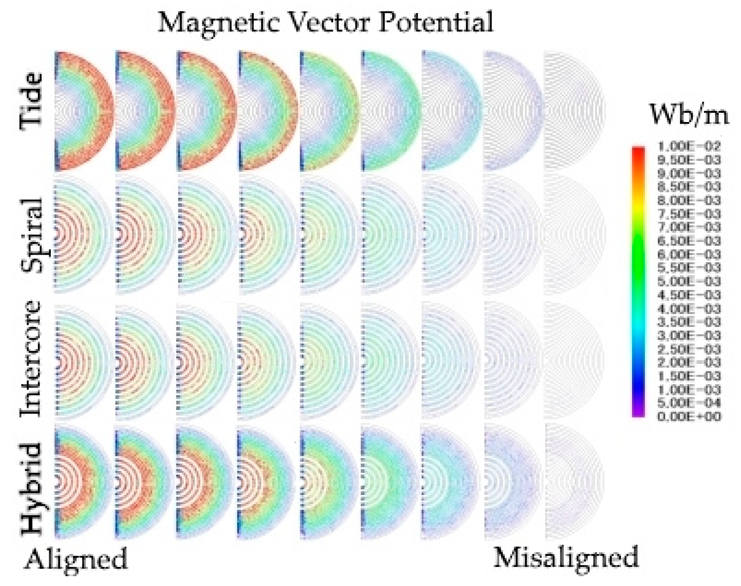
6.1.2. Visual Representation
6.2. Measurements Results
6.2.1. Pure Resistive Load
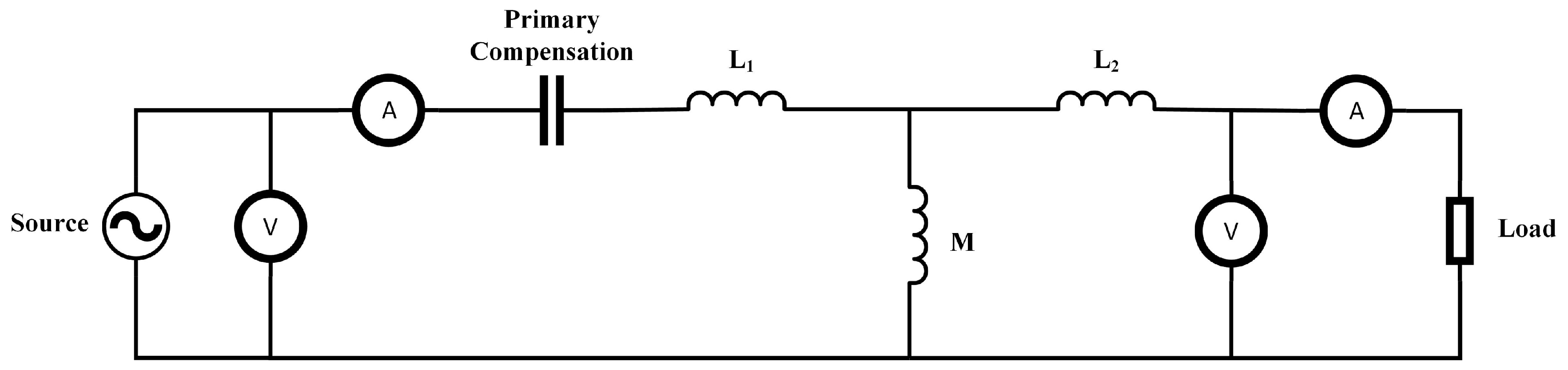
6.2.2. Primary Compensation with Resistive Load
7. Discussion
7.1. Simulations
7.1.1. Graphs
7.1.2. Visual Representation
7.1.3. Simulation Overview
7.2. Measurements
7.2.1. Pure Resistive Load
7.2.2. Primary Compensation with Resistive Load
7.2.3. Measurement Overview
8. Conclusions
Author Contributions
Funding
Acknowledgments
Conflicts of Interest
Nomenclature
| Magnetic vector potential | |
| ATO | Automatic train operation |
| CAD | Computer-aided design |
| d | Lateral misalignment |
| d1, d2 | Distance from the primary substrate to the primary winding and secondary winding |
| Distance from the secondary substrate to the primary winding and secondary winding | |
| E(k) | Elliptical integral of the second kind |
| FEM | Finite element method |
| h1, h2 | Winding heights in the axial direction for primary winding and secondary winding |
| J | Current density |
| J0, J1 | Bessel function of the first kind |
| K(k) | Elliptical integral of the first kind |
| LRT | Light rail transit |
| M | Mutual inductance |
| Mtotal | Total mutual inductance calculated for all coil using the superposition method |
| µ0 | Permeability of the free space |
| µ1, µ2 | Relative permeability of the substrates |
| Angular frequency | |
| φ | Integration angle |
| Rp | Distance between the primary winding and the reference axis |
| Rs | Distance between the secondary winding and the reference axis |
| rms | Root-mean-square |
| t1–t4 | Substrate thickness |
| θ | Angular misalignment |
| WPT | Wireless power transfer |
| Z | Total mutual inductance |
| Zc | Additional mutual impedance due to the utilization of magnetic substrate |
References
- Vltcarioca Home Page. Available online: http://www.vltcarioca.rio (accessed on 18 May 2018).
- Kaemppert, W. A Popular History of American Invention; C. Scribner’s Sons: New York, NY, USA, 1924; pp. 106–133. [Google Scholar]
- Electric Transport in Latin America Home Page. Available online: http://www.tramz.com/br/cp/cp/html (accessed on 18 May 2018).
- Yarra Trams Home Page. Available online: http://www.yarratrams.com.au (accessed on 18 May 2018).
- Dart Home Page. Available online: http://www.dart.org (accessed on 18 May 2018).
- Ratp Home Page. Available online: http://www.ratp.fr/en (accessed on 18 May 2018).
- Bomsinal Home Page. Available online: http://www.bomsinal.com (accessed on 18 May 2018).
- TTC Home Page. Available online: http://www.ttc.ca (accessed on 18 May 2018).
- Land Transport Authority Home Page. Available online: http://www.lta.gov.sg (accessed on 18 May 2018).
- Tbm Home Page. Available online: http://www.infotbm.com/en (accessed on 18 May 2018).
- Caf Home Page. Available online: http://www.caf.net/en/ecocaf/nuevas-soluciones/tranvia-greentech.php (accessed on 18 May 2018).
- Becker, F.; Dämmig, A. Catenary free operation of light rail vehicles—Topology and operational concept. In Proceedings of the 2016 18th European Conference on Power Electronics and Applications (EPE’16 ECCE Europe), Karlsruhe, Germany, 5–9 September 2016. [Google Scholar] [CrossRef]
- Rail Journal Home Page. Available online: http://www.railjournal.com/index.php/asia/battery-electric-trains-for-japans-oga-line.html (accessed on 18 May 2018).
- Primove Home Page. Available online: http://www.primove.bombardier.com/applications/tram.html (accessed on 18 May 2018).
- Ukita, K.; Kashiwagi, T.; Sakamoto, Y.; Sasakawa, T. Evaluation of a non-contact power supply system with a figure-of-eight coil for railway vehicles. In Proceedings of the 2015 IEEE PELS Workshop on Emerging Technologies: Wireless Power (2015 WoW), Daejeon, Korea, 5–6 June 2015. [Google Scholar] [CrossRef]
- Cho, D.; Jung, G.; Yoon, U.; Lee, B. Development & Implementation of Electric Tram System with Wireless Charging Technology. ICT Express 2015, 1, 34–38. [Google Scholar] [CrossRef]
- Lee, S.H.; Lorenz, R.D. Development and Validation of Model for 95%-Efficiency 220-W Wireless Power Transfer Over a 30-cm Air Gap. IEEE Trans. Ind. Appl. 2011, 47, 2495–2504. [Google Scholar] [CrossRef]
- Li, Y.; Mai, R.; Lin, T.; Sun, H.; He, Z. A Novel WPT System Based on Dual Transmitters and Dual Receivers for High Power Applications: Analysis, Design and Implementation. Energies 2017, 10. [Google Scholar] [CrossRef]
- Mude, K.N.; Bertoluzzo, M.; Buja, G.; Pinto, R. Design and experimentation of two-coil coupling for electric city-car WPT charging. J. Electromagn. Waves Appl. 2016, 30, 70–88. [Google Scholar] [CrossRef]
- Yamamoto, K.; Maruyama, T.; Kondo, K.; Kashiwagi, T. A Study on the circuit configuration with capacitors to compensate the power factor for high-power contactless power transformer. In Proceedings of the 2013 International Conference on Electrical Machines and Systems (ICEMS), Busan, Korea, 26–29 October 2013; pp. 2233–2238. [Google Scholar]
- Dias, J.V.P.P.; Miyatake, M. Misalignment based electric circuit of a wireless power transfer transformer for light rail transit. In Proceedings of the 2017 20th International Conference on Electrical Machines and Systems (ICEMS), Sydney, NSW, Australia, 11–14 August 2017. [Google Scholar] [CrossRef]
- Luo, S.; Takada, Y.; Koseki, T. Experimental Verification of Sensor-less Coil Position Control System and its Gap Deviation Tolerance Improvement Method in Wireless Power Transmission System of Electrical Trains (自動車 交通・電気鉄道合同研究会 鉄道一般,エネルギーストレージシステムの応用). 電気学会研究会資料 VT 2015, 2015, 19–24. [Google Scholar]
- Hwang, K.; Cho, J.; Kim, D.; Park, J.; Kwon, H.J.; Kwak, I.S.; Park, H.H.; Ahn, S. An Autonomous Coil Alignment System for the Dynamic Wireless Charging of Electric Vehicles to Minimize Lateral Misalignment. Energies 2017, 10. [Google Scholar] [CrossRef]
- Villa, J.L.; Sallán, J.; Llombart, A.; Sanz, J.F. Design of a high frequency Inductively Coupled Power Transfer system for electric vehicle battery charge. Appl. Energy 2009, 86, 355–363. [Google Scholar] [CrossRef]
- Steinmetz, C.P. Theory and Calculation of Alternating Current Phenomena, 1st ed.; Electrical World and Engineer, Inc.: New York, NY, USA, 1900; pp. 195–236. Available online: https://archive.org/details/theorycalculatio00steiiala (accessed on 15 May 2018).
- Maxwell, J. A Treatise on Electricity and Magnetism, 3rd ed.; Dover Publications Inc.: New York, NY, USA, 1954; pp. 138–222. Available online: https://archive.org/details/ATreatiseOnElectricityMagnetism-Volume2 (accessed on 15 May 2018).
- Anele, A.O.; Hamam, Y.; Chassagne, L.; Linares, J.; Alayli, Y.; Djouani, K. Computation of the Mutual Inductance between Air-Cored Coils of Wireless Power Transformer. J. Phys. Conf. Ser. 2015, 633. [Google Scholar] [CrossRef]
- Su, Y.P.; Liu, X.; Hui, S.Y.R. Mutual Inductance Calculation of Movable Planar Coils on Parallel Surfaces. IEEE Trans. Power Electron. 2009, 24, 1115–1123. [Google Scholar] [CrossRef]
- Luo, Z.; Wei, X. Analysis of Square and Circular Planar Spiral Coils in Wireless Power Transfer System for Electric Vehicles. IEEE Trans. Ind. Electron. 2018, 65, 331–341. [Google Scholar] [CrossRef]
- Valtchev, S.; Borges, B.; Brandisky, K.; Klaassens, J.B. Resonant Contactless Energy Transfer with Improved Efficiency. IEEE Trans. Power Electron. 2009, 24, 685–699. [Google Scholar] [CrossRef]
- Dias, J.V.P.P.; Kim, H.; Jang, D. Computer model for railway inductive power supply using Valtchev model. In Proceedings of the 2011 International Conference on Electrical Machines and Systems, Beijing, China, 20–23 August 2011. [Google Scholar] [CrossRef]
- Hurley, W.G.; Duffy, M.C. Calculation of self and mutual impedances in planar magnetic structures. IEEE Trans. Magn. 1995, 31, 2416–2422. [Google Scholar] [CrossRef]
- Wilcox, D.J.; Hurley, W.G.; Conlon, M. Calculation of self and mutual impedances between sections of transformer windings. IEE Proc. C-Gener. Transm. Distrib. 1989, 136, 308–314. [Google Scholar] [CrossRef]
- Hurley, W.G.; Duffy, M.C. Calculation of self- and mutual impedances in planar sandwich inductors. IEEE Trans. Magn. 1997, 33, 2282–2290. [Google Scholar] [CrossRef]
- Liu, X.; Hui, S.Y. Optimal Design of a Hybrid Winding Structure for Planar Contactless Battery Charging Platform. IEEE Trans. Power Electron. 2008, 23, 455–463. [Google Scholar] [CrossRef]
- Hurley, W.G.; Duffy, M.C.; Zhang, J.; Lope, I.; Kunz, B.; Wölfle, W.H. A Unified Approach to the Calculation of Self- and Mutual-Inductance for Coaxial Coils in Air. IEEE Trans. Power Electron. 2015, 30, 6155–6162. [Google Scholar] [CrossRef]
- Dias, J.V.P.P.; Miyatake, M. Improved core shape of contacless transformer for LRT system. In Proceedings of the 2015 International Conference on Electrical Systems for Aircraft, Railway, Ship Propulsion and Road Vehicles (ESARS), Aachen, Germany, 3–5 March 2015. [Google Scholar] [CrossRef]
- Tan, L.; Li, J.; Chen, C.; Yan, C.; Guo, J.; Huang, X. Analysis and Performance Improvement of WPT Systems in the Environment of Single Non-Ferromagnetic Metal Plates. Energies 2016, 9. [Google Scholar] [CrossRef]
- Wen, F.; Huang, X. Optimal Magnetic Field Shielding Method by Metallic Sheets in Wireless Power Transfer System. Energies 2016, 9. [Google Scholar] [CrossRef]
- Toshiba. Available online: http://www.toshiba-tmat.co.jp/en/res/theme4.htm (accessed on 18 May 2018).
- Kazimierczuk, M.K. High-Frequency Magnetic Components, 1st ed.; John Wiley & Sons: Chichester, UK, 2009; pp. 412–470. [Google Scholar]
- JMAG Home Page. Available online: http://www.jmag-international.com (accessed on 18 May 2018).


| Air Gap | Coil Diameter | Wire Diameter | Ferrite Diameter | Ferrite Width | Shielding Diameter | Shielding Width | Carbody Diameter | Carbody Width |
|---|---|---|---|---|---|---|---|---|
| 10 mm | 82 mm | 2 mm | 82 mm | 4 mm | 164 mm | 0.1 mm | 164 mm | 1 mm |
| Coil Design | Turns | Intercore Ferrite Width | Intercore Ferrite Layers |
|---|---|---|---|
| Tide | 19 | - | - |
| Spiral | 10 | - | - |
| Intercore | 10 | 2 mm | 10 |
| Hybrid | 15 | 2 mm | 5 |
© 2018 by the authors. Licensee MDPI, Basel, Switzerland. This article is an open access article distributed under the terms and conditions of the Creative Commons Attribution (CC BY) license (http://creativecommons.org/licenses/by/4.0/).
Share and Cite
Pinon Pereira Dias, J.V.; Miyatake, M. Increase in Robustness against Effects of Coil Misalignment on Electrical Parameters Using Magnetic Material Layer in Planar Coils of Wireless Power Transfer Transformer. Energies 2018, 11, 1970. https://doi.org/10.3390/en11081970
Pinon Pereira Dias JV, Miyatake M. Increase in Robustness against Effects of Coil Misalignment on Electrical Parameters Using Magnetic Material Layer in Planar Coils of Wireless Power Transfer Transformer. Energies. 2018; 11(8):1970. https://doi.org/10.3390/en11081970
Chicago/Turabian StylePinon Pereira Dias, Joao Victor, and Masafumi Miyatake. 2018. "Increase in Robustness against Effects of Coil Misalignment on Electrical Parameters Using Magnetic Material Layer in Planar Coils of Wireless Power Transfer Transformer" Energies 11, no. 8: 1970. https://doi.org/10.3390/en11081970