Article

Quantitative Comparisons of Six-Phase Outer-Rotor Permanent-Magnet Brushless Machines for Electric Vehicles

1
School of Energy and Environment, City University of Hong Kong, 83 Tat Chee Avenue, Kowloon Tong, Hong Kong, China
2
Research Laboratory of Electronics, Massachusetts Institute of Technology, Cambridge, MA 02139, USA
*
Author to whom correspondence should be addressed.
Energies 2018, 11(8), 2141; https://doi.org/10.3390/en11082141
Submission received: 20 July 2018 / Revised: 10 August 2018 / Accepted: 11 August 2018 / Published: 16 August 2018
(This article belongs to the Special Issue Permanent Magnet Synchronous Machines)

Abstract

:
Multiphase machines have some distinct merits, including the high power density, high torque density, high efficiency and low torque ripple, etc. which can be beneficial for many industrial applications. This paper presents four different types of six-phase outer-rotor permanent-magnet (PM) brushless machines for electric vehicles (EVs), which include the inserted PM (IPM) type, surface PM (SPM) type, PM flux-switching (PMFS) type, and PM vernier (PMV) type. First, the design criteria and operation principle are compared and discussed. Then, their key characteristics are addressed and analyzed by using the finite element method (FEM). The results show that the PMV type is quite suitable for the direct-drive application for EVs with its high torque density and efficiency. Also, the IPM type is suitable for the indirect-drive application for EVs with its high power density and efficiency.

1. Introduction

In recent years, interest in electrical vehicles (EVs) is growing rapidly driven by the concerns about environment issues [1,2]. EVs are environmentally friendly and enjoy many attractive merits compare to their tradition fossil-fuel counterparts [3]. In particular, EVs offer definite advantages for fossil-fuel use reduction, which causes less harmful gases, lower cost of driving, cost-effective maintenance, less noise and vibration. Also, EVs provide more comfort at low speed than their conventional fossil-fuel counterparts.
The electric machines for EVs are regarded as one of the key components of the whole EV system [4]. In order to ensure the driving quality of EVs, there are many strict requirements for the EV machines [5,6]. First of all, high reliability is essential for the challenging environment and frequent starting and stopping during driving. Secondly, a high power density is desirable for weight reduction. Moreover, high efficiency is particularly important for a better economic outcome. Nowadays, there are several types of electric machines available for EV applications. In the early years of EV development, DC motors were considered as the mainstream because of their easy control and excellent speed regulation [7]. However, they suffer from fragile mechanical structures, poor thermal dissipation and low efficiency, which are not desirable features for EV application. Then, AC asynchronous machines attracted much attention because of their high efficiency and simple structure [8,9]. However, they suffer from problems such as complex control algorithms and low torque density. Permanent-magnet synchronous (PMS) brushless machines which enjoy the high efficiency, high power density and high reliability, are considered an attractive option for EV applications [10,11]. In particular, the permanent-magnet flux-switching (PMFS) type and permanent-magnet vernier (PMV) type, as the representatives of PMS brushless machines, are extraordinary for EV use. The PMFS type is a combination of a synchronous machine and a switched reluctant machine [12], which enjoys high torque density and a robust rotor structure [13], so it can enhance the high performance for EVs. The PMV type integrates a coaxial magnetic gear into a PM brushless machine. In this way, it is capable of achieving a high electric frequency at low rotation speed [14]. Meanwhile, it always adopts a concentric winding layout in order to have short end windings, which is more suitable for the limited space of EVs., The general advantages and disadvantages of the four different types of machines are summarized in Table 1 [15,16,17].
Moreover, multiphase machines with a higher degree of freedom have fault-tolerant capability, so they are suitable for EVs, and can also be considered a great option [18,19]. In addition, the outer-rotor structure of these machines, which are designed with a rotating outer structure and a fixed inner structure, is quite attractive for EV applications [20]. In this way, the structure has better performance for EV propulsion.
This paper is focused on four different types of six-phase outer-rotor PM machines, which are suitable for EV applications. These four types of machines combine the advantages of PM machines and multiphase machines, thus achieving high power density, high torque density, better fault tolerance capability, and lower torque ripple. The key is to quantitatively compare the operation performance of the four different types of machines, namely the inserted PM (IPM) type, surface PM (SPM) type, PM flux-switching (PMFS) type, and PM vernier (PMV) type. First, the design criteria and operating principles are elaborated in Section 2. Then, a quantitative comparison of the machines is described in Section 3, which includes the key characteristics, normal operation performance, and the fault-tolerant operation. Finally, the conclusions of the quantitative comparison are summarized in Section 4.

2. Proposed Six-Phase Machine Topologies and Operation Principles

The proposed topologies are presented with both cross-section and exploded views in Figure 1. These four machine types adopt the six-phase arrangement and outer-rotor structure. Figure 1a shows the IPM topology with PMs inserted inside the rotor, while Figure 1b shows the SPM type with PMs mounted on the surface of the rotor. The main difference between the IPM machine and the SPM machine is their arrangements of PMs. Figure 1c shows the topology of PMFS machine, while Figure 1d shows the PMV machine topology. The PMFS machine has all PMs inserted inside the stator teeth, while the PMV machine has PMs mounted on both stator side and rotor side.
The operating speed n of the machine is governed by the pole pairs and the electric frequency of the proposed machines:
  n = 60 f p  
where f is the electric frequency and p is the pole-pairs of the machines.
The turns of armature coil N a can be determined by the following relationship:
N a = α a R a S a 4 ρ L a  
where α a is the factor of slots filling, S a is the slot area of the coil, and L a is the average coil length. In this paper, the turns of armature coil of each phase and slot filling factor for the proposed machines are set to be 200 and 40%, respectively.
To achieve the fair comparison, the peripheral dimension, PM volume, air gap length and current density, are set as equal.

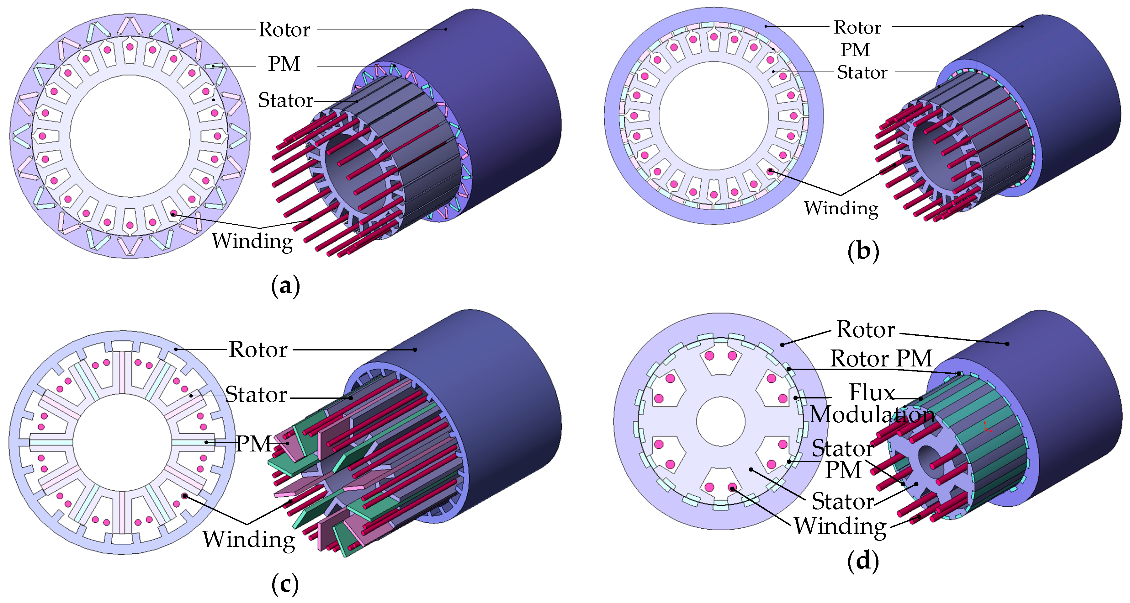
2.1. Proposed IPM Type and SPM Type

The IPM machine adopts the V-shape PM poles inserted within its rotor. As investigated, it has been suggested that the V-shape or W-shape PM poles would have the better operation performance than the traditional radial PM arrangement [21]. Moreover, in order to prevent the short-circuiting PM fluxes, the magnetic insulation material is purposely implemented. The IPM type adopts the single-layer fractional slot concentrated winding, which can reduce the end winding length and decrease the copper loss [22]. In fact, the IPM machine consists of 24 stator slots and 10 pole pairs, while the mechanical and electrical degrees between two slots can be calculated as [23]:
  α m = 360 ° z = 360 ° 24 = 15 °  
  α e = p 360 ° z = 10 × 360 ° 24 = 150 °  
where z is the number of stator slots and p is the pole pairs. According to Equations (3) and (4), the mechanical angle is 15° and the electrical angle is 150° for each adjacent stator slot. In this case, the stator is able to produce a rotating magnet field with six-phase current. Referring to the principle of minimum magnetoresistance, namely the flux tends to flow along the path of minimum magnetoresistance and the rotor will rotate synchronously with the rotating magnetic field produced by the stator.
The SPM machine shares the same stator structure with IPM type, while the PM arrangement of the two machines are different. Unlike the IPM type with installed PMs within its stator, the SPM accommodates the PMs on the rotor surface. The SPM machine adopts the single layer distributed winding layout and consists of 24 stator slots and 20 pole pairs. Consequently, its mechanical degree and electrical degree between two slots can be found to be 15° and 300°, respectively.

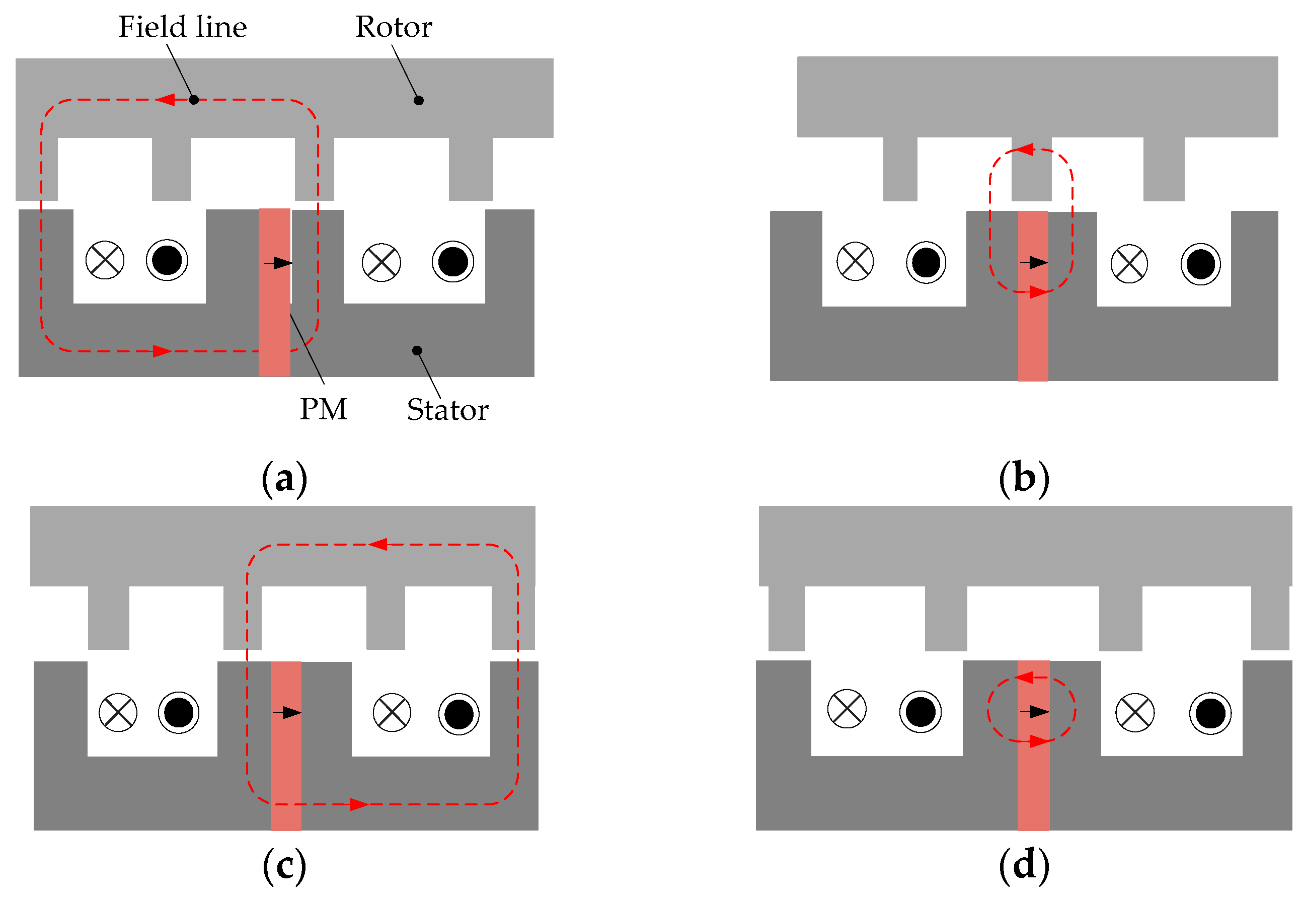
2.2. Proposed PMFS Type

The proposed six-phase outer-rotor PMFS machine consists of 12 stator slots and 22 salient rotor poles. It combines the special features of a switched reluctance machine and a synchronous machine, hence enjoying the advantages of robust rotor structure, high power density and high torque density. The PMs are inserted in each stator tooth with the opposite direction in each two adjacent ones. The proposed machine adopts the double-layer concentrated winding method, where each coil is around a stator tooth with PM inserted in the middle of it.
The machine follows the flux switching principle [24], which is shown in Figure 2. Four typical positions are shown. First, as shown in Figure 2a, the right part of the stator tooth aligns directly with one of the rotor teeth, so it provides the largest flux linkage. Second, as shown in Figure 2b, the stator tooth is completely misaligned with the rotor tooth. Consequently, no magnetic flux flows in-between them. Also, the flux linkage of the coil is reduced to zero. Third, as shown in Figure 2c, the left part of the stator tooth aligns directly again to another rotor tooth, so it provides the largest flux linkage. Finally, as shown in Figure 2d, the flux linkage of the coil decreases to zero again.
Actually, the number of stator slots and rotor pole-pairs are critical for the PMFS machine. The flux linkage and steady torque can be influenced substantially [25]. Since the magnetization direction of each two adjacent PMs are opposite, the number of PMs should be an even number. Thus, the number of stator slots N s should be an even number as well. As a result, the number of stators of a six-phase machine should be a multiple of six, i.e., N s = 2   km , k = 1, 2, 3, …etc. With this setting, N s can be determined as twelve. The relationship between stator pole number N s and rotor pole number N r is governed by [25]:
N r = ( 12 ± n ) N s 6  
where n is a positive integer and should not be the multiple times of three. For the proposed six-phase machine, it adopts the combination of 12 stator slots and 22 rotor teeth.

2.3. PMV Type

The proposed six-phase outer-rotor PMV machine consists of six stator teeth each with three flux modulation poles. The machine adopts the double-layer concentrated winding with each phase coil fitting around one stator tooth. It installs PMs on both its stator side and rotor side. Meanwhile, the consequent pole structure is employed to improve the utilization of PM materials.
The PMV machine utilizes the concept of magnetic-gearing effect, hence achieving the high-torque low-speed capability. The flux modulation poles (FMPs) are introduced into the stator teeth of the proposed machine. The lower rotating speed PM field is modulated to couple with the higher rotating speed stator air gap magnetic field. Consequently, a self-governing speed effect results. Thus, when the outer rotor PM moves a little angle at a low speed, there will be a great change of flux interacting with the magnet field generated by the rotating armature winding. According to the magnetic gearing effect, the number of pole pairs of flux density distribution in the space harmonic is produced by the high speed stator winding rotating magnetic field and low speed rotor pole magnetic field as [26]:
p m , k = m p r + k Q s m = 1 ,   3 ,   5 ,   ,   k = 0 , ± 1 , ± 2 , ± 3 ,   ±
where Q s is the number of FMP and p r is the number of rotor PM pole-pairs. Furthermore, the operating speed of the flux density in space harmonic Ω r can be described as:
Ω m , k = m p r m p r + k Q s Ω r
when m = 1 and n = 1, the harmonic magnetic field of the air gap results in the largest modulated magnitude. Thus, the number of rotor magnet poles becomes:
p r = Q s p s
where p s is the number of winding pole-pairs. For the proposed six-phase outer-rotor PMV machine, the number of rotor pole pairs is selected as 17, the number of winding pole pairs is 1, and the number of flux modulation poles as 18. Consequently, the gear ratio is given as:
G r = p r Q s p r = 17 18 17 = 1 17

3. Performance Comparison

In this section, the key operation characteristics, such as the magnetic flux distribution line, air gap flux density, flux linkage, no-load EMF, cogging torque, steady torque and power loss of the proposed machines, are analyzed and compared by using the finite element method (FEM) with the JMAG Designer tool.
Moreover, the fault-tolerant operation performance of each machine is demonstrated and compared with the normal operation. Table 2 shows the key parameters of the four proposed six-phase outer-rotor PM machines, which follow the abovementioned comparison conditions.

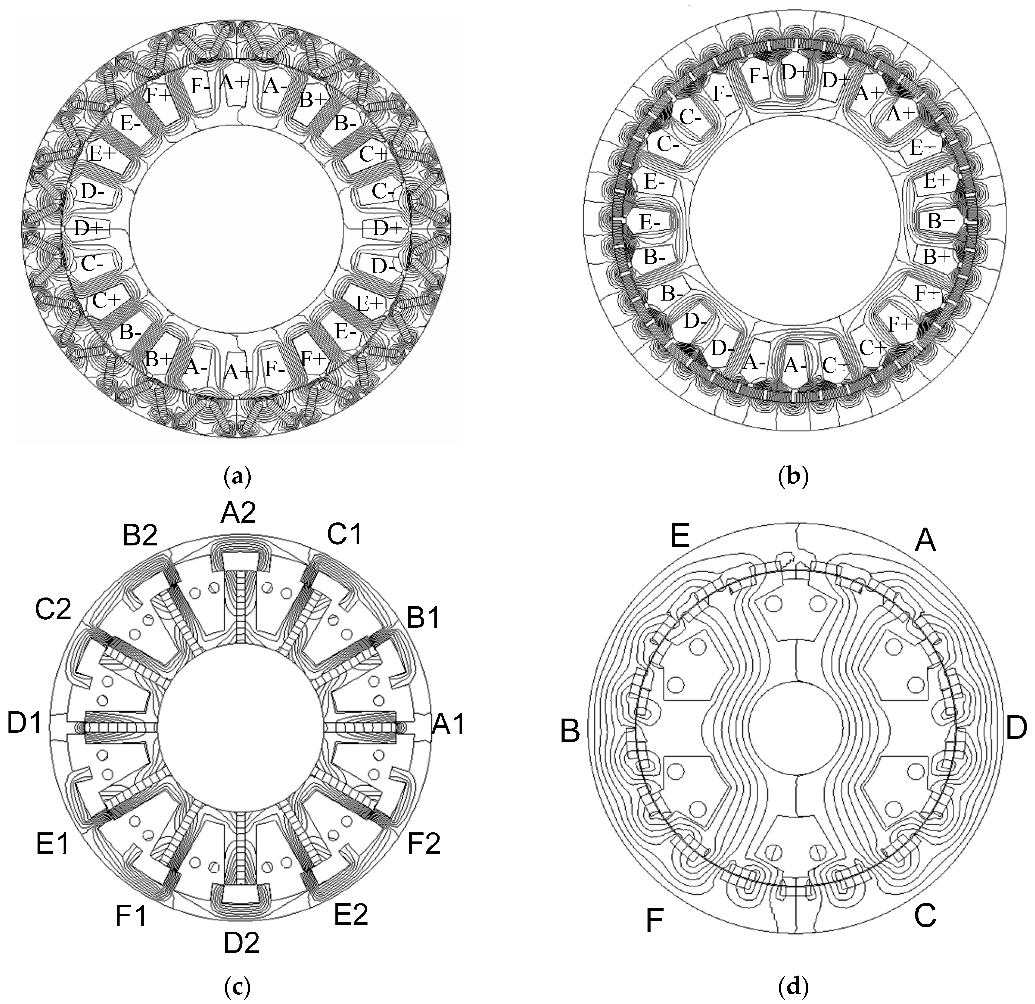
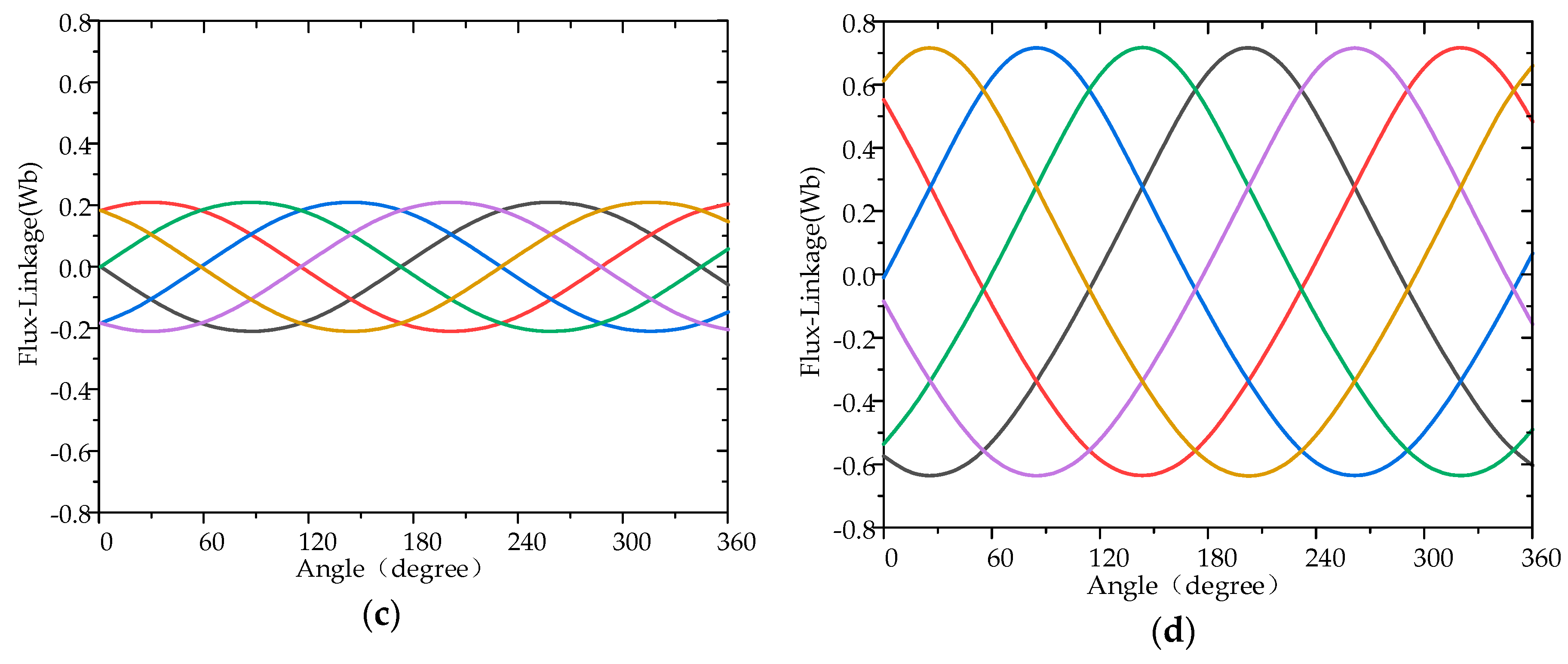
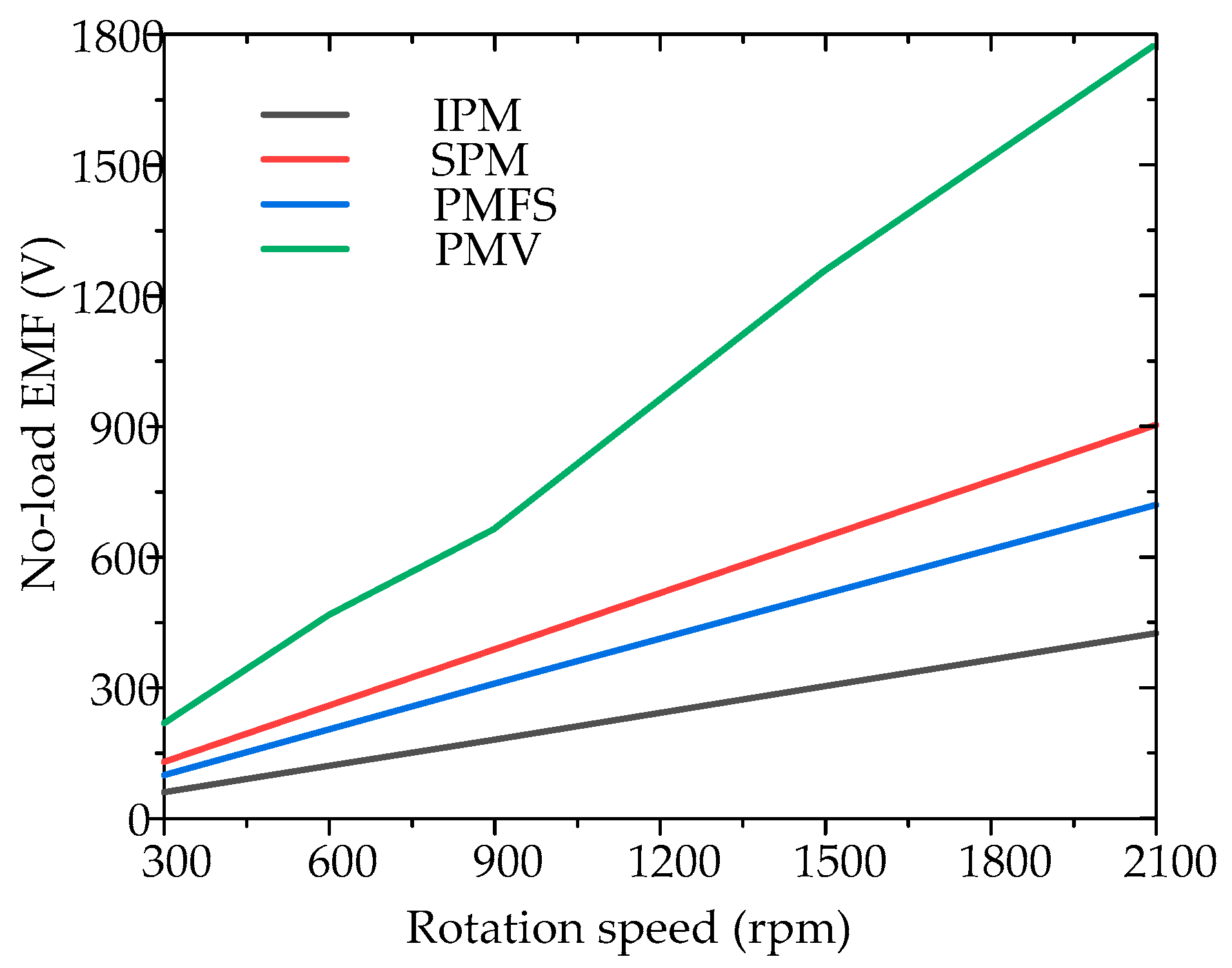
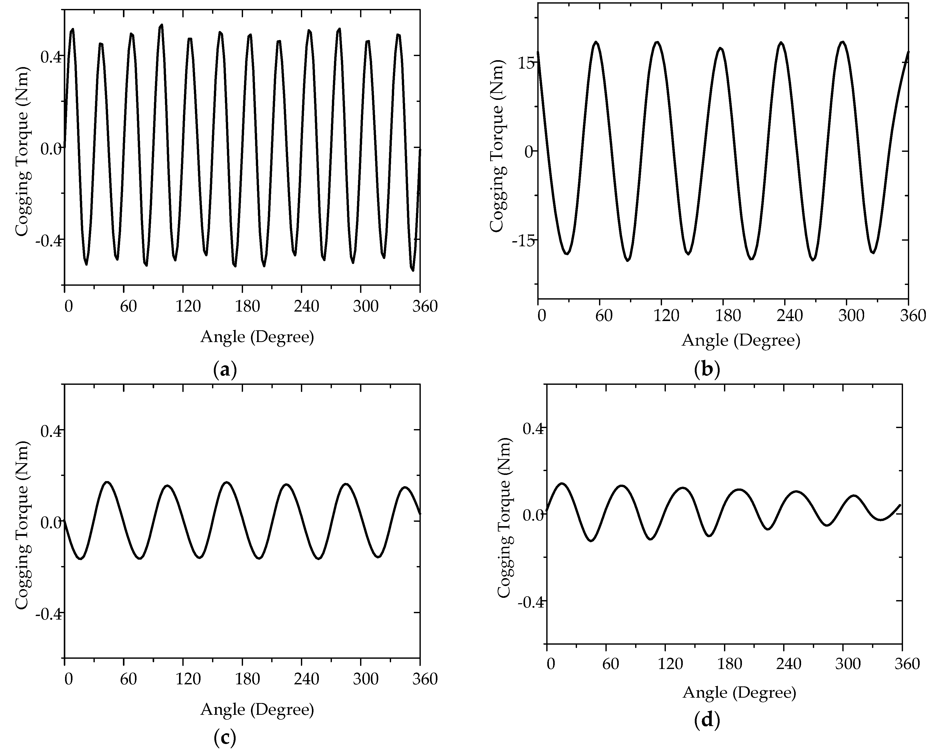
3.1. Basic Characteristics

Firstly, the magnetic flux distribution and winding distribution of these four proposed machines at generating mode are presented in Figure 3. The IPM type and SPM type both adopt the single-layer winding arrangement, while the PMFS type and PMV type adopt the double-layer winding arrangement. The air gap flux density of the four proposed machines are shown in Figure 4, the maximum of the air gap flux-density are 0.8 T, 1.4 T, 2.5 T and 2.0 T, respectively. In general, the higher flux density will provide a higher torque density [27], so among the four machines the proposed PMV type and the PMFS type have the potential to produce the better performance. In addition, the flux-linkage of the four proposed machines are shown in Figure 5, which indicates that all the proposed machines can offer the balance flux-linkage among the six-phase patterns.
Second, the no-load EMF is governed by [28]:
E = d ψ d t  
where Ψ is no-load flux-linkage shown in Figure 5. Hence, the no-load EMF should be high, since the no-load flux-linkage sinusoidal wave changes rapidly with the time and has a high amplitude. The RMS values of no-load EFM at different rotation speeds are presented in Figure 6. It can be seen that the output voltage has the positive correlation with the rotation speed. The PMV type has the highest no-load voltage over the four machines due to the magnetic gearing effect. Hence, the rated rotation speed of the four machines are determined as 2000, 1000, 1000 and 600 r/min. The waveforms of the no-load EMFs are presented in Figure 7. The amplitudes of the no-load EMF of IPM type, SPM type, PMFS type and PMV type are 582, 615, 524 and 576 V, respectively.

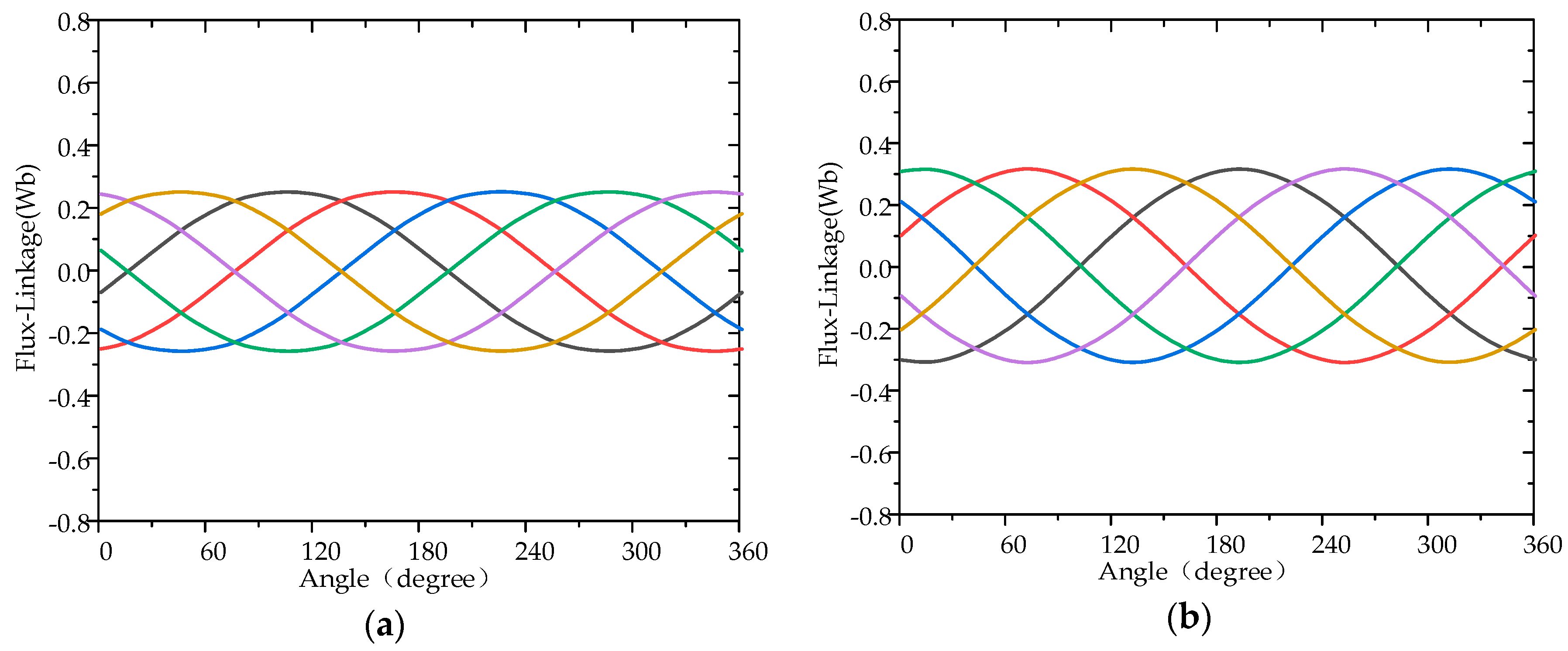
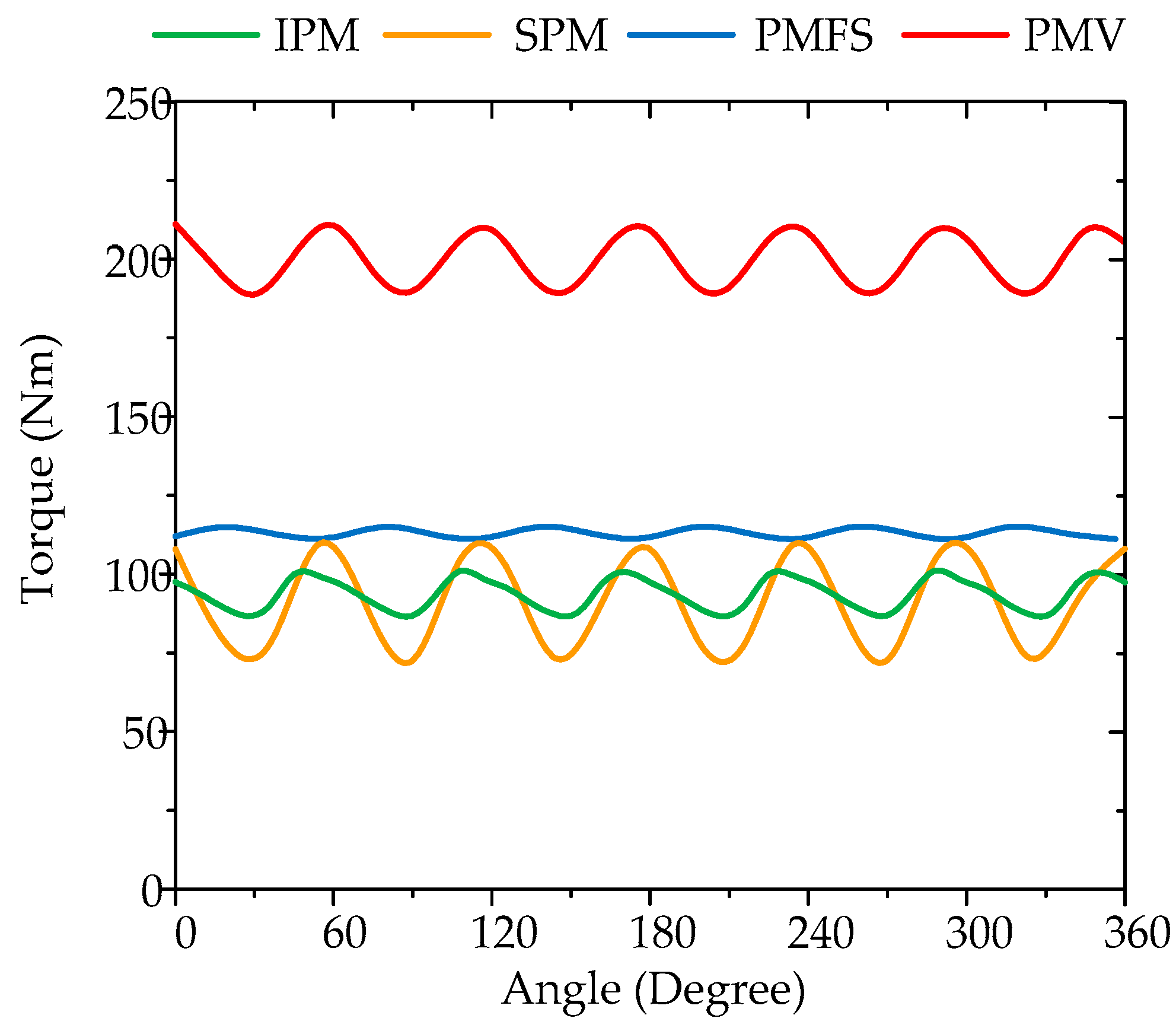
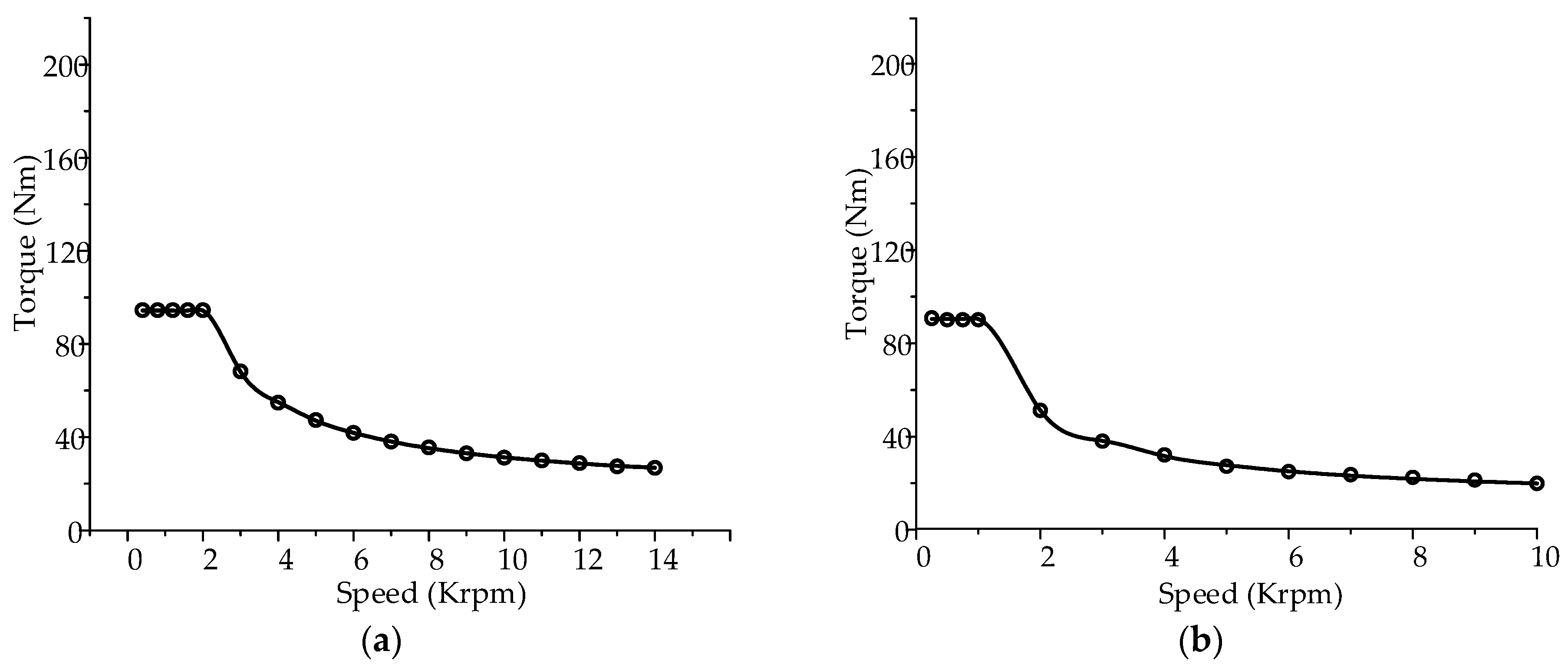
3.2. Normal Operation

The normal operations of the proposed machines are analyzed and discussed. These machines operate at 2000, 1000, 1000 and 600 r/min, respectively, which runs with the current density of 6 A/mm2. The steady torque of the machines are given in Figure 8, which are 93.93, 91.14, 113.38 and 199.91 N·m, respectively. It can be found that the steady torque of PMV type is the largest, which is nearly 50% larger than the three counterparts. Moreover, the steady torque of IPM type and SPM type are very similar. However, the torque ripple of IPM type is much smaller than SPM type. In addition, the PMFS type has the smallest torque ripple among the four machines. The torque-speed characteristic of the four proposed machines are shown in Figure 9.
Furthermore, the torque density of each machine can be calculated as:
S T = T m a x V  
where V is the volume of electric machine. In this way, the torque density of the four proposed machines are 24.71, 23.98, 29.83 and 52.58 kN·m/m³, respectively, so the PMV type has the best torque density among the four types.
In addition to this, the torque ripple is given as:
T r i p = T m a x T i n T a v g × 100 %
so, the torque ripples of the four proposed machines are 15.52%, 40.25%, 3.83% and 11.88%, respectively.
In addition, Figure 10 shows the cogging torque of the four proposed machines. Cogging torque is a distinctive problem of PM machines which results from the interaction between the PMs and the stator iron core when the armature winding is not electrified [29]. Cogging torque causes mechanical vibration and noise [30,31], and it can be reduced by certain ways such as changing the magnet shape [32]. The period of cogging torque is:
T c o g = 360 L C M ( z ,   2 p )
where LMC is the least common multiple of the stator slots number z and number of poles 2p. It can be seen that the SPM type suffers from a large cogging torque because of its slot number and pole-pair number combination [33,34]. Compared to the SPM type, the IPM type has a remarkably reduced cogging torque with a similar steady torque. The percentages of cogging torque to steady torque of the four machines are 0.58%, 17.56%, 1.59% and 1.00%, respectively. Hence, it can be concluded that except for the SPM type, the other three types are desirable in terms of cogging since they are well below 3%.
Moreover, the power losses and efficiency of the proposed machines are calculated by FEM. The iron losses of the IPM type, SPM type, PMFS type and PMV type machine are 1014, 1914, 1438 and 649 W, respectively. The copper loss of the SPM type is the highest, since it is the only one with a distributed winding. The values of the eddy current loss, hysteresis loss, copper loss and efficiency of each machine, are shown in Table 3.

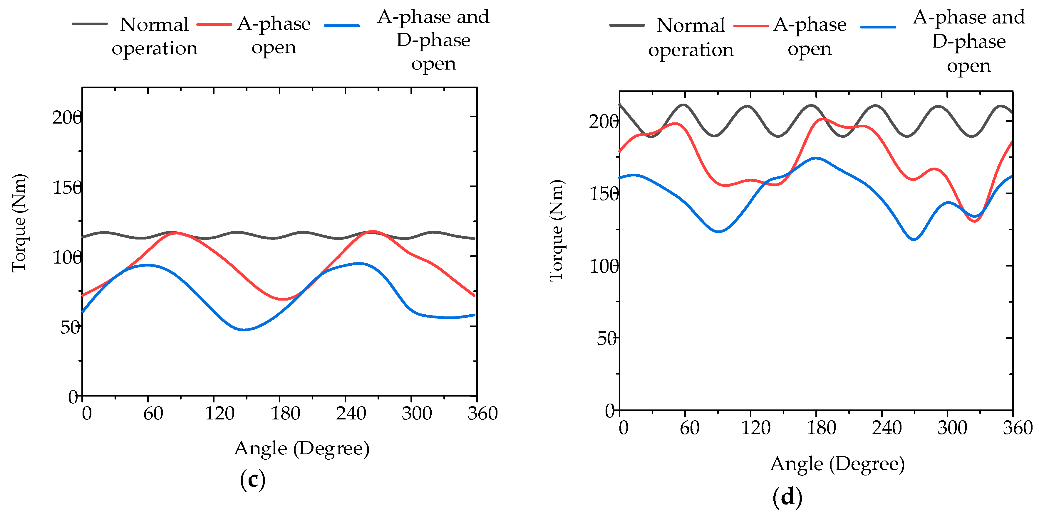
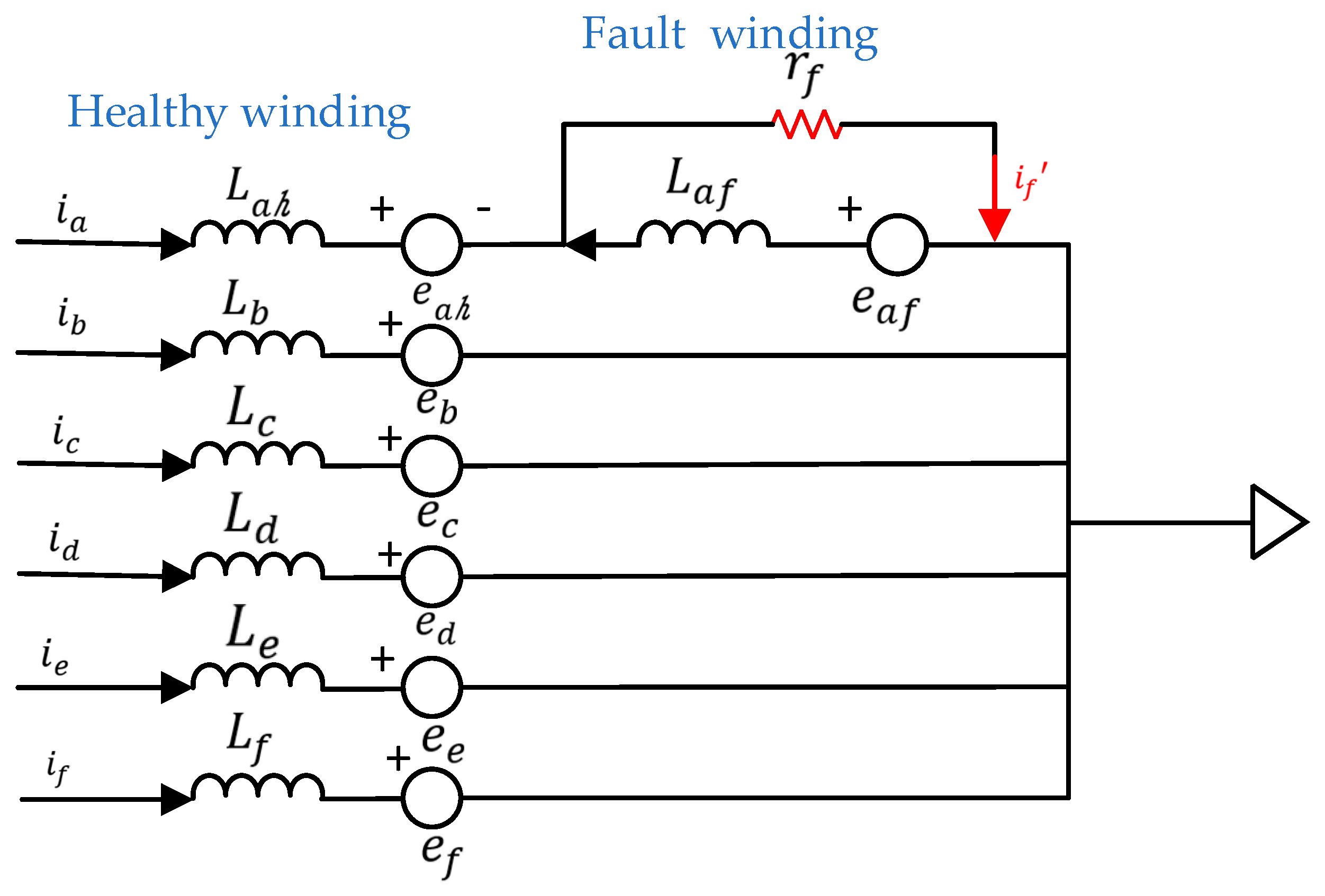
3.3. Fault-Tolorant Operation Performance

Reliability is a vital characteristic of machines used for EV applications. One can improve the operation reliability by adopting the multiphase than the traditional three-phase. In order to verify the fault-tolerant operation performance for the proposed six-phase machines, the open-phase fault case and short-circuit fault case are simulated and discussed.
Figure 11 shows the steady torque of the proposed machines with A-phase open fault, and A-phase and D-phase both open faults. Also, the normal operation steady torque under motoring mode is given for comparison. It can be seen that the IPM type and SPM type have a large reduction of the average torque, when they meet the open-phase fault, while the PMV type has the smallest influence by the open-phase fault.
In addition, there may also be the short-circuit faults during the EV operation. Actually, it’s considered as the most severe fault over all the winding faults in electrical machines [35], since the current value of the fault turns will become much higher than the healthy turns and there will be excessive heat generated in the fault phase [36]. In fact, this kind of fault is mostly caused by winding insulation humidity, overvoltage, overheating, etc. Figure 12 shows the electric model of an A-phase short-circuit fault. When a short-circuit fault occurs to A-phase, a resistor r f which represents the fault connection in the model and r f →0. Once the fault occurs, a circuit through r f is created. The system equation is (14). This equation shows that during a short-circuit fault, the healthy windings the six-phase PM machines can remain working [37]. Rows 1 to 6 show the healthy part and the influence of the fault part. The seventh row shows the fault circuit current model which is influenced by the winding turns included in the fault.
( v a v b v c v d v e v f 0 ) = ( r s 0 0 0 0 0 r a f 0 r s 0 0 0 0 0 0 0 r s 0 0 0 0 0 0 0 r s 0 0 0 0 0 0 0 r s 0 0 0 0 0 0 0 r s 0 r a f 0 0 0 0 0 r a f + r f ) ( i a i b i c i d i e i f i f ) + ( L a h M a h b M a h c M a h d M a h e M a h f M a h a f M a h b L b M b c M b d M b e M b f M b a f M a h c M b c L c M c d M c e M c f M c a f M a h d M b d M c d L d M d e M d f M d a f M a h e M b e M c e M d e L e M e f M e a f M a h f M b f M c f M d f M e f L f M f a f M a h a f M b a f M c a f M d a f M e a f M f a f L a f ) d d t ( i a i b i c i d i e i f i f ) + ( e a e b e c e d e e e f e a f )
Figure 13 shows that the steady torque of 50% short-circuit of A-phase occurs to the proposed machines for both the six-phase winding and three-phase winding configurations. It can be seen that the torque ripple of the three-phase winding is larger than six-phase winding configuration in normal operation. When a short-circuit fault occurs, the torque ripple of a three-phase winding is much larger than that of a six-phase as well. Moreover, under six-phase winding conditions, the torque of all the proposed machines are still periodical and the average torque only shows a little decrease. This indicates that the four proposed machines have good fault tolerance ability when short-circuit faults occur.
It should be noted that for practical normal conditions, the results generally won’t be changed. This is well proven by most researchers with the help of FEA design [38,39,40]. However, for practical harsh conditions, the results may be different to some degree. As we know, machines suffer from many unexpected problems in harsh conditions, such as high temperature, large overcurrent, iron breakage issues, PM fixing problems, etc. In general, the salient machine should have a high robustness for intermittent operation [41,42,43], and the PMFS type meets this condition by having a relatively high robustness for harsh conditions.

4. Conclusions

This paper presents four six-phase outer-rotor PM machines with different working principles, which include the IPM type, SPM type, PMFS type and PMV type. The working principle of each machine has been elaborated and discussed. By analyzing the operating performance of the four machines, it is shown that the PMV type has the best operating performance and fault tolerance ability among the four machines, so it is more suitable for electric vehicle applications. The key parameters of working performance are summarized in Table 4. Moreover, the evaluation of the four types of machines proposed is summarized in Table 5.
Thus, based on the above analysis and discussion, we can conclude the following from the comparison:
  • The PMV type can produce the largest steady torque under the low rotation speed.
  • Based on the operation principle, the PMV type can be used for in-wheel direct-drive EV applications.
  • The arrangement of PMs for the PMFS type can protect the PMs from rotational stresses, which is also suitable for EV applications.
  • The SPM type should be carefully considered for EV applications, since it has the high cogging torque and the lowest related efficiency.
  • The outer-rotor topology can be directly connected with the tire rim of the EV.
  • The multiphase machine has a good fault tolerance ability, which is suitable for EV applications.

Author Contributions

The work presented in this paper is the output of the research projects undertaken by C.L. In specific, Y.Y. and C.L. developed the topic, designed the system, analyzed the results, and wrote the paper. C.H.T.L. helped to provide the guidance and review the paper.

Acknowledgments

This work was supported by a grant (Project No.: ECF Project 92/2016) from Energy and Conservation Fund of HKSAR, China. Also, it was supported a grant (Project No.: ITS/353/16) from ITF Tier3 of Innovation and Technology Commission (ITC) of HKSAR, China.

Conflicts of Interest

The authors declare no conflict of interest.

References

  1. Un-Noor, F.; Padmanaban, S.; Mihet-Popa, L.; Mollah, M.N.; Hossain, E. A comprehensive study of key electric vehicle (EV) components, technologies, challenges, impacts, and future direction of development. Energies 2017, 10, 1217. [Google Scholar] [CrossRef]
  2. Chau, K.T.; Chan, C.C.; Liu, C. Overview of Permanent-Magnet Brushless Drives for Electric and Hybrid Electric Vehicles. IEEE Trans. Ind. Electron. 2008, 55, 2246–2257. [Google Scholar] [CrossRef] [Green Version]
  3. De Santiago, J.; Bernhoff, H.; Ekergård, B.; Eriksson, S.; Ferhatovic, S.; Waters, R.; Leijon, M. Electrical Motor Drivelines in Commercial All-Electric Vehicles: A Review. IEEE Trans. Veh. Technol. 2012, 61, 475–484. [Google Scholar] [CrossRef] [Green Version]
  4. Lulhe, A.M.; Date, T.N. A technology review paper for drives used in electrical vehicle (EV) & hybrid electrical vehicles (HEV). In Proceedings of the 2015 International Conference on Control, Instrumentation, Communication and Computational Technologies (ICCICCT), Kumaracoil, Tamilnadu, 18–19 December 2015; pp. 632–636. [Google Scholar]
  5. Lee, C.H.T.; Chau, K.T.; Liu, C. Design and Analysis of an Electronic-Geared Magnetless Machine for Electric Vehicles. IEEE Trans. Ind. Electron. 2016, 63, 6705–6714. [Google Scholar] [CrossRef]
  6. Jenal, M.; Sulaiman, E.; Kumar, R. Effects of rotor pole number in outer rotor permanent magnet flux switching machine for light weight electric vehicle. In Proceedings of the 4th IET Clean Energy and Technology Conference (CEAT 2016), Kuala Lumpur, Malaysia, 14–15 November 2016; pp. 1–6. [Google Scholar]
  7. Rahim, N.A.; Ping, H.W.; Tadjuddin, M. Design of an In-Wheel Axial Flux Brushless DC Motor for Electric Vehicle. In Proceedings of the 2006 International Forum on Strategic Technology, Ulsan, Korea, 18–20 October 2006; pp. 16–19. [Google Scholar]
  8. Reddy, G.V.V.; Reddy, B.P.; Sivakumar, K. Design constraints of multiphase induction motor drives for electric vehicles. In Proceedings of the 2017 National Power Electronics Conference (NPEC), Pune, India, 18–20 December 2017; pp. 234–239. [Google Scholar]
  9. Ulu, C.; Korman, O.; Kömürgöz, G. Electromagnetic and thermal analysis/design of an induction motor for electric vehicles. In Proceedings of the 2017 8th International Conference on Mechanical and Aerospace Engineering (ICMAE), Jeju, Korea, 21–24 November 2017; pp. 6–10. [Google Scholar]
  10. Gu, W.; Zhu, X.; Quan, L.; Du, Y. Design and optimization of permanent magnet brushless machines for electric vehicle applications. Energies 2015, 8, 13996–14008. [Google Scholar] [CrossRef]
  11. Zhang, L.; Fan, Y.; Li, C.; Liu, C. Design and Analysis of a New Six-Phase Fault-Tolerant Hybrid-Excitation Motor for Electric Vehicles. IEEE Trans. Magn. 2015, 51, 1–4. [Google Scholar] [PubMed]
  12. Mbadiwe, E.I.; Sulaiman, E.; Khan, F. Consideration of permanent magnet flux switching motor in segmented rotor for in-wheel vehicle propulsion. In Proceedings of the 2018 International Conference on Computing, Mathematics and Engineering Technologies (iCoMET), Sukkur, Pakistan, 3–4 March 2018; pp. 1–6. [Google Scholar]
  13. Tang, Y.; Ilhan, E.; Paulides, J.J.H.; Lomonova, E.A. Design considerations of flux-switching machines with permanent magnet or DC excitation. In Proceedings of the 2013 15th European Conference on Power Electronics and Applications (EPE), Lille, France, 3–5 September 2013; pp. 1–10. [Google Scholar]
  14. Oner, Y.; Zhu, Z.Q.; Chu, W. Comparative Study of Vernier and Interior PM Machines for Automotive Application. In Proceedings of the 2016 IEEE Vehicle Power and Propulsion Conference (VPPC), Hangzhou, China, 17–20 October 2016; pp. 1–6. [Google Scholar]
  15. Gudivada, R.; Bodnapu, K.K.; Vavillapalli, K.R. Virtual characterization of Interior Permanent Magnet (IPM) motor for EV traction applications. In Proceedings of the 2017 IEEE Transportation Electrification Conference (ITEC-India), Pune, India, 13–15 December 2017; pp. 1–4. [Google Scholar]
  16. Shu, Z.; Zhu, X.; Quan, L.; Du, Y.; Liu, C. Electromagnetic performance evaluation of an outer-rotor flux-switching permanent magnet motor based on electrical-thermal two-way coupling method. Energies 2017, 10, 677. [Google Scholar] [CrossRef]
  17. Abdel-Khalik, A.S.; Ahmed, S.; Massoud, A. A new permanent-magnet vernier machine using a single layer winding layout for electric vehicles. In Proceedings of the 2014 IEEE 23rd International Symposium on Industrial Electronics (ISIE), Istanbul, Turkey, 1–4 June 2014; pp. 703–708. [Google Scholar]
  18. Tong, C.; Wu, F.; Zheng, P.; Sui, Y.; Cheng, L. Analysis and design of a fault-tolerant six-phase permanent-magnet synchronous machine for electric vehicles. In Proceedings of the 2014 17th International Conference on Electrical Machines and Systems (ICEMS), Hangzhou, China, 22–25 October 2014; pp. 1629–1632. [Google Scholar]
  19. Huang, J.; Kang, M.; Yang, J.Q.; Jiang, H.B.; Liu, D. Multiphase machine theory and its applications. In Proceedings of the 2008 International Conference on Electrical Machines and Systems, Wuhan, China, 17–20 October 2008; pp. 1–7. [Google Scholar]
  20. Zhao, J.; Zheng, Y.; Zhu, C.; Liu, X.; Li, B. A Novel Modular-Stator Outer-Rotor Flux-Switching Permanent-Magnet Motor. Energies 2017, 10, 937. [Google Scholar] [CrossRef]
  21. Wang, A.; Jia, Y.; Soong, W.L. Comparison of Five Topologies for an Interior Permanent-Magnet Machine for a Hybrid Electric Vehicle. IEEE Trans. Magn. 2011, 47, 3606–3609. [Google Scholar] [CrossRef]
  22. Zhang, X.; Ji, J.; Zheng, J.; Zhu, X. Improvement of Reluctance Torque in Fault-Tolerant Permanent-Magnet Machines with Fractional-Slot Concentrated-Windings. IEEE Trans. Appl. Superconduct. 2018, 28, 1–5. [Google Scholar] [CrossRef]
  23. Fan, Y.; Chen, S.; Tan, C.; Cheng, M. Design and investigation of a new outer-rotor IPM motor for EV and HEV in-wheel propulsion. In Proceedings of the 2016 19th International Conference on Electrical Machines and Systems (ICEMS), Chiba, Japan, 17 March 2016; pp. 1–4. [Google Scholar]
  24. Yu, J.; Liu, C. Design of a double-stator hybrid flux switching permanent magnet machine for direct-drive robotics. In Proceedings of the 2017 20th International Conference on Electrical Machines and Systems (ICEMS), Sydney, Australia, 11–14 August 2017; pp. 1–6. [Google Scholar]
  25. Chen, J.T.; Zhu, Z.Q.; Thomas, A.S.; Howe, D. Optimal combination of stator and rotor pole numbers in flux-switching PM brushless AC machines. In Proceedings of the 2008 International Conference on Electrical Machines and Systems, Wuhan, China, 17–20 October 2008; pp. 2905–2910. [Google Scholar]
  26. Atallah, K.; Howe, D. A novel high-performance magnetic gear. IEEE Trans. Magn. 2001, 37, 2844–2846. [Google Scholar] [CrossRef]
  27. Shan, Z.; Liu, C.; Lee, C.H.T.; Chen, W.; Yu, F. Design and Comparison of Direct-Drive Stator-PM Machines for Electric Power Generation. In Proceedings of the 2016 IEEE Vehicle Power and Propulsion Conference (VPPC), Hangzhou, China, 17–20 October 2016; pp. 1–6. [Google Scholar]
  28. Saeed, M.S.R.; Mohamed, E.E.M.; Ali, A.I.M. Parallel Partitioned-Rotor Switched flux PM machine for light hybrid/electric vehicles. In Proceedings of the 2018 International Conference on Innovative Trends in Computer Engineering (ITCE), Aswan, Egypt, 19–21 February 2018; pp. 380–385. [Google Scholar]
  29. Zhu, Z.Q.; Howe, D. Influence of design parameters on cogging torque in permanent magnet machines. IEEE Trans. Energy Convers. 2000, 15, 407–412. [Google Scholar] [CrossRef] [Green Version]
  30. Li, Z.; Chen, J.H.; Zhang, C.; Liu, L.; Wang, X. Cogging torque reduction in external-rotor permanent magnet torque motor based on different shape of magnet. In Proceedings of the 2017 IEEE International Conference on Cybernetics and Intelligent Systems (CIS) and IEEE Conference on Robotics, Automation and Mechatronics (RAM), Ningbo, China, 19–21 November 2017; pp. 304–309. [Google Scholar]
  31. Liu, Y.; Yin, J.; Gong, B.; Yang, G. Comparative analysis of cogging torque reduction methods of variable flux reluctance machines for electric vehicles. In Proceedings of the 2017 20th International Conference on Electrical Machines and Systems (ICEMS), Sydney, Australia, 11–14 August 2017; pp. 1–6. [Google Scholar]
  32. Setiabudy, R.; Rahardjo, A. Cogging torque reduction by modifying stator teeth and permanent magnet shape on a surface mounted PMSG. In Proceedings of the 2017 International Seminar on Intelligent Technology and Its Applications (ISITIA), Surabaya, Indonesia, 28–29 August 2017; pp. 227–232. [Google Scholar]
  33. Lee, D.H.; Jeong, C.L.; Hur, J. Analysis of cogging torque and torque ripple according to unevenly magnetized permanent magnets pattern in PMSM. In Proceedings of the 2017 IEEE Energy Conversion Congress and Exposition (ECCE), Cincinnati, OH, USA, 1–5 October 2017; pp. 2433–2438. [Google Scholar]
  34. Ma, G.; Li, G.; Zhou, R.; Guo, X.; Ju, L.; Xie, F. Effect of stator and rotor notches on cogging torque of permanent magnet synchronous motor. In Proceedings of the 2017 20th International Conference on Electrical Machines and Systems (ICEMS), Sydney, Australia, 11–14 August 2017; pp. 1–5. [Google Scholar]
  35. Wu, F.; Zheng, P.; Jahns, T.M. Analytical Modeling of Interturn Short Circuit for Multiphase Fault-Tolerant PM Machines with Fractional Slot Concentrated Windings. IEEE Trans. Ind. Appl. 2017, 53, 1994–2006. [Google Scholar] [CrossRef]
  36. Zhang, S.; Habetler, T.G. A transient model of interior permanent magnet machines under stator winding inter-turn short circuit faults. In Proceedings of the IECON 2017–43rd Annual Conference of the IEEE Industrial Electronics Society, Beijing, China, 5–8 November 2017; pp. 1765–1770. [Google Scholar]
  37. Kim, K.-H.; Choi, D.-U.; Gu, B.-G.; Jung, I.-S. Fault model and performance evaluation of an inverter-fed permanent magnet synchronous motor under winding shorted turn and inverter switch open. IET Electr. Power Appl. 2010, 4, 214–225. [Google Scholar] [CrossRef]
  38. Zhang, Y.; Chau, K.T.; Jiang, J.Z.; Zhang, D.; Liu, C. A finite element–analytical method for electromagnetic field analysis of electric machines with free rotation. IEEE Trans. Magn. 2006, 42, 3392–3394. [Google Scholar] [CrossRef]
  39. Liu, C.; Chau, K.T.; Zhong, J.; Li, W.; Li, F. Quantitative Comparison of Double-Stator Permanent Magnet Vernier Machines With and Without HTS Bulks. IEEE Trans. Appl. Supercond. 2012, 22, 5202405. [Google Scholar]
  40. Liu, C.; Chau, K.T.; Li, W. Loss analysis of permanent magnet hybrid brushless machines with and without HTS field windings. IEEE Trans. Appl. Supercond. 2012, 22, 1077–1080. [Google Scholar]
  41. Liu, C. Emerging electric machines and drives—An overview. IEEE Trans. Energy Convers. 2018. [Google Scholar] [CrossRef]
  42. Chen, M.; Chau, K.T.; Li, W.; Liu, C. Development of Non-rare-earth Magnetic Gears for Electric Vehicles. J. Asian Electr. Veh. 2012, 10, 1607–1613. [Google Scholar] [CrossRef]
  43. Liu, C.; Luo, Y. Overview of advanced control strategies for electric machines. Chin. J. Electr. Eng. 2017, 3, 53–61. [Google Scholar]
Figure 1. Proposed six-phase outer-rotor machine topologies: (a) IPM type; (b) SPM type; (c) PMFS type; (d) PMV type.
Energies 11 02141 g001
Figure 2. Working principle of PMFS type at four typical positions: (a) Positon 1; (b) Position 2; (c) Position 3; (d) Position 4.
Energies 11 02141 g002
Figure 3. Magnetic flux distribution of proposed six-phase outer-rotor PM machines: (a) IPM type; (b) SPM type; (c) PMFS type; (d) PMV type.
Energies 11 02141 g003
Figure 4. Airgap flux-density of proposed six-phase outer-rotor PM machines: (a) IPM type; (b) SPM type; (c) PMFS type; (d) PMV type.
Energies 11 02141 g004
Figure 5. No-load flux-linkage of proposed six-phase outer-rotor PM machines: (a) IPM type; (b) SPM type; (c) PMFS type; (d) PMV type.
Energies 11 02141 g005aEnergies 11 02141 g005b
Figure 6. RMS of no-load EMFs of proposed six-phase outer-rotor PM machines under different speeds.
Energies 11 02141 g006
Figure 7. No-load EMF of proposed six-phase outer-rotor PM machines: (a) IPM type; (b) SPM type; (c) PMFS type; (d) PMV type.
Energies 11 02141 g007aEnergies 11 02141 g007b
Figure 8. Steady torque of proposed six-phase outer-rotor PM machines.
Energies 11 02141 g008
Figure 9. Torque-speed characteristic of proposed six-phase outer-rotor machines: (a) IPM type; (b) SPM type; (c) PMFS type; (d) PMV type.
Energies 11 02141 g009aEnergies 11 02141 g009b
Figure 10. Cogging torque of proposed six-phase outer-rotor PM machines: (a) IPM type; (b) SPM type; (c) PMFS type; (d) PMV type.
Energies 11 02141 g010
Figure 11. Torque at open-phase fault of proposed six-phase outer-rotor PM machines: (a) IPM type; (b) SPM type; (c) PMFS type; (d) PMV type.
Energies 11 02141 g011aEnergies 11 02141 g011b
Figure 12. Six-phase star connection electrical model of A-phase short circuit fault.
Energies 11 02141 g012
Figure 13. Steady torque of proposed outer-rotor PM machines of both six-phase and three-phase occur to short-circuit condition: (a) IPM type; (b) SPM type; (c) PMFS type; (d) PMV type.
Energies 11 02141 g013
Table 1. Comparison of Four Proposed Types of Machines.
Machine TypeAdvantages Disadvantages
IPM
  • Simple and mature
  • Easy manufacture
  • Mature control strategy
  • High speed operation
  • Relatively large torque ripple
  • PM fixing problem
SPM
PMFSM
  • Robost rotor structure
  • Good heat dissipation
  • Easy winding
  • Difficult manufacturing
  • Special design
  • Relatively large torque ripple
PMVM
  • Low speed operation
  • High torque density
  • Complex structure
  • Special design
Table 2. Key Parameters of Proposed Six-phase Outer-rotor PM Machines.
Items IPMSPMPMFSMPMVM
Outer rotor diameter220 mm220 mm220 mm220 mm
Stator diameter179 mm179 mm197 mm169 mm
Air gap0.5 mm0.5 mm0.5 mm0.5 mm
Stack length 100 mm100 mm100 mm100 mm
PM volume 406 cm3406 cm3406 cm3406 cm3
PM thickness 5 mm5 mm5 mm5 mm
Stator slots24241218
Rotor pole-pairs10202217
Table 3. Iron Loss of Proposed Six-phase Machines.
ItemIPMSPMPMFSPMV
Eddy current loss874 W1763 W1291 W424 W
Hysteresis loss 140 W151 W147 W225 W
Copper loss163 W283 W178 W197 W
Other loss200 W200 W200 W200 W
Overall power21,047 W11,461 W13,686 W13,678 W
Efficiency 93.45%79.09%86.73%92.89%
Table 4. Working Performance of Proposed Six-phase Outer-rotor Machines.
ItemsIPMSPMPMFSPMV
Torque ripple15.52%40.25%3.83%11.88%
Torque density24.71 kN·m/m³23.98 kN·m/m³29.83 kN·m/m³52.58 kN·m/m³
Efficiency 93.45%79.09%86.73%92.89%
Power 21,047 W11,461 W13,686 W13,678 W
Base speed2000 r/min1000 r/min1000 r/min600 r/min
Table 5. Evaluation of Proposed Machines.
ItemsIPMSPMPMFSPMV
Efficency highmoderatemoderatehigh
Torque densitymoderatemoderatemoderatehigh
Thermal dissipaition moderatemoderategoodmoderate
Cost effectivelyness moderatelowmoderatehigh

