On the Injection of Sub/Inter-Harmonic Current Components for Active Anti-Islanding Purposes


Department of Electrical and Computer Engineering, Democritus University of Thrace, ECE Campus Kimmeria, 67132 Xanthi, Greece
*
Author to whom correspondence should be addressed.
Energies 2018, 11(9), 2183; https://doi.org/10.3390/en11092183
Submission received: 28 June 2018
/
Revised: 10 August 2018
/
Accepted: 17 August 2018
/
Published: 21 August 2018
(This article belongs to the Section F: Electrical Engineering)
Abstract
:Active anti-islanding schemes that are based on the injection of harmonic currents, such as the measurement of the impedance at a specific frequency or similar techniques, have been proposed for anti-islanding protection in photovoltaic (PV) systems due to their low impact on inverter active power, their fast detection response in island, and reduced non-detection zone (NDZ). Integer multiples of the fundamental frequency as well as sub/inter-harmonics have both been used for the implementation of those schemes. Although utilization of sub/inter-harmonics present significant advantages, they also present significant limitations. This work investigates those limitations, particularly the ones that are caused by the parallel operation of multiple inverters. In addition, the distortion effect that is caused in the output current of the widely used PV microinverters with pseudo dc-link (PV Pdc-MICs) is discussed and thoroughly analyzed. It is concluded that when the injection is performed asynchronously (without communication among the inverters) sub/inter-harmonics are unsuitable for utilization under the parallel operation of multiple inverters. It is worth noting that a strategy is proposed in the current work that retains the effectiveness of the harmonic injection scheme under the injection of integer multiples of fundamental frequency. On the other hand, the distortion effect that is caused by the sub/inter-harmonics on PV Pdc-MICs output current, has been evaluated as insignificant when harmonics are used for anti-islanding purposes. Finally, the theoretical/mathematical outcomes of this work are supported by simulation and experimental results.
Keywords:
anti-islanding; PV inverters; MIC; microinverter; harmonics; sub-harmonics; inter-harmonics1. Introduction
Active anti-islanding schemes that measure the impedance at a specific frequency have been intensively developed over the past years consisting an attractive solution for anti-islanding protection in interconnected PV installations. In contrast to other active schemes [1] that either degrade considerably the output power quality of the PV-inverter, such as the Sliding Mode Frequency Shift (SMFS) [2], the Active Phase Shift (APS) [2], and the Sandia Frequency Shift (SFS), or reduce the energy yield of the PV-panel (such as the Sandia Voltage Shift (SVS) and APS techniques), impedance measuring (at a specific frequency) schemes have very low impact on the PV-inverter active power, whereas they maintain a fast response to the island and a reduced Non Detection Zone (NDZ) [3]. Those schemes in principal inject periodically a signal at a specific frequency (usually a harmonic current component) and afterwards evaluate the grid response—at that frequency—by means of measuring the inverter output impedance [4]. Techniques that use harmonic current components to estimate the grid condition have also been referenced in relevant literature, providing (more or less) the same advantages with impedance measurement techniques [2]; in principal, those schemes also rely on the inverter output impedance to estimate grid condition at Point of Common Coupling (PCC) [5,6,7]. Typical values of the injected signal frequency are in the range of 20 and 400 Hz, depending on parameters such as the resonant frequency of inverter output filter, the harmonic content of utility grid etc. A comprehensive study regarding the impedance measuring techniques using various current components (including sub/inter-harmonics and integer multiples of fundamental frequency) is presented in [8]. Besides the integer multiple of the fundamental frequency there are some works that utilize sub/inter-harmonics. In [4] a 75 Hz current component has been used to measure the impedance at the fundamental frequency. In [9] a triangular 20 Hz current component is periodically injected and grid condition at PCC is estimated by using a cross-correlation method. In [3] a modified version of the cross-correlation anti-islanding method in [6] is used, utilizing a 25 Hz current component, in order to compare against 2nd-order harmonic component injection. Finally, many works that are referenced in [8], utilize inter-harmonics current components. Evidently, the anti-islanding techniques that inject sub/inter-harmonics current components have received some attention in the research community; it is recalled that sub/inter-harmonics refer to frequencies below the fundamental as well as to frequencies above the fundamental. Those techniques mainly rely on the low interference of the sub/inter-harmonics with grid pre-existing (voltage) harmonics. Indeed, sub/inter-harmonics are unlikely to interfere with grid harmonics, which are in general integer multiples of the fundamental frequency and in particular the 3rd, 5th and 7th ones (according to EN 50160 [10]). Additionally, according to [3] sub-harmonics as well as low frequency inter-harmonics (e.g., close to fundamental frequency) can be advantageous because they are capable of inducing higher magnitudes of voltage components, enhancing the effectiveness of the anti-islanding technique without compromising the inverter output power quality. It is worth mentioning that the utilization of sub/inter-harmonics close to the fundamental frequency (as is the 75 Hz for European grids that is used in [4]) can be advantageous, because of the direct translation of the impedance at the fundamental frequency.
However, utilizing sub/inter-harmonics may have significant (negative) impact on the islanding scheme. Some disadvantages of sub/inter-harmonics, such as interfering with the control scheme of the inverter (in case that a sub/inter-harmonic close to the fundamental frequency is chosen), or highly restricted magnitudes according to grid codes (imposing serious implementation issues in the —non-dedicated—PV platforms) are well known in scientific community [2,4]; the difficulties of implementing active anti-islanding schemes in PV platforms have been initially raised in [4], referring to the impedance measurement techniques. Moreover, some problems regarding voltage-flickering and transformers saturation caused by low frequency subharmonics have been reported in [2]. However, those problems are either easily dealt or insignificant when they are caused by anti-islanding schemes (e.g., the interfering problems with the control scheme). This is because the magnitude of those schemes is typically restricted to low values in order to cope with the relevant power quality standards, as the IEC 61727 [11]. Despite the fact that from grid point of view sub/inter-harmonics are harmless, yet significant issues may rise regarding the anti-islanding scheme itself, when sub/inter-harmonics are used. However, those issues have not been sufficiently investigated in the relevant literature. Some works have focused on the synchronization among the inverters [12] and [13], whereas the work in [14] has proposed a method to avoid the harmonic cancelling among the inverters that is caused by the closed-loop current control of Voltage Source PV-inverters (PV-VSI). Nevertheless, the abovementioned works (as well as most of the aforementioned works) do not take into account the significant cancelling effect that is caused when multiple inverters with the same harmonic injection anti-islanding technique are connected at PCC without synchronization; this effect is different from the cancelling effect that is caused by the inverters control-loop and is a rather important issue, considering the massive penetration of Distributed Energy Resources (DER) in public grids worldwide. As it will be shown next, the lack of communication among the inverters makes sub/inter-harmonics unsuitable in case of multiple inverters operating in parallel. On the other hand, establishing some kind of communication, as the work in [12] proposes, would lead to a complex anti-islanding scheme. However, the effectiveness of such a scheme is still questionable due to the marginal reliability of communications. Last but not least, the works utilizing sub/inter-harmonics focus mainly on PV-VSIs, ignoring the widely used category of PV-microinverters; PV-microinverters consist a modular-technology with many advantages over the centralized string and multistring-based topologies [15,16,17], which have been intensively developed in the USA due to its National Code (a comprehensive review on microinverters is presented in [17] and [18]). As it will be shown next, passing sub/inter-harmonics throughout the unfolder of this technology leads to a distortion of the generated harmonic current that may affect the effectiveness of the implemented anti-islanding scheme.
In this work, the abovementioned issues are thoroughly analyzed. In particular, a mathematical analysis is presented highlighting the problem that is caused by the parallel operation of multiple inverters, which leads to the disqualification of sub/inter-harmonics. At the same time, a strategy is proposed among the inverters to retain the effectiveness of the anti-islanding scheme when integer multiples of the fundamental frequency are used. It is worth mentioning that the proposed strategy does not require any kind of communication among the inverters nor it increases the complexity of the anti-islanding algorithm. Regarding the distortion that is observed in PV-microinverters, this is thoroughly analyzed and modelled. In addition, its impact on two suitable impedance based anti-islanding techniques, the one that measures the impedance at 75 Hz (similar to the one that has been proposed in [4]) and the recently proposed one for Pdc-MICs in [6], is discussed. Based on the presented analysis, it is concluded that the impact of the distortion on both the aforementioned techniques is limited. This is due to the low amounts of harmonic components that are typically used by the anti-islanding schemes in order to meet the relevant power quality standards (as the IEC 61727). As it will be shown next, such low amounts hardly distort the inverter output current. On the other hand, the mathematical model of the distortion is of generic usage and it can be used in several other applications where injected currents of larger values are used.
The rest of the paper is organized as follows: initially, Section 2.1.1 describes the structure of a PV-microinverter with an unfolder (referring to the microinverters with a Pseudo dc-link, Pdc-MICs). Next (Section 2.1.2), the distortion that is caused by the sub/inter-harmonics is analyzed and modelled, leading to some important conclusions regarding their suitability in the anti-islanding schemes of [4] and [6]. Section 2.2 analyzes the impact of multiple inverters operating in parallel. Based on the presented results the suitable injection frequencies for use in parallel operation of multiple inverters are presented, disqualifying both the sub-harmonics and the inter-harmonics. Important conclusions regarding the periodicity of the harmonic injection and power quality considerations, are also extracted. Last but not least, a proposal is made that retains the effectiveness of the harmonic injection-based schemes (when integer multiples of the fundamental frequency are utilized), without needing communication among the inverters. Finally, Section 3 and Section 5 conclude the paper. Simulation as well as experimental results that support the theoretical outcomes of Section 2.2 are presented in Section 2.1.3 and Section 2.1.4 respectively, whereas the theoretical outcomes of Section 2.2 are supported only by simulation results, presented in Section 2.2.1.
2. Results
2.1. Sub/Inter-Harmonics in the PV-Microinverters with a Pseudo dc-Link
2.1.1. Description of a PV-Microinverter with a Pseudo dc-Link and Harmonic Injection Capability
Figure 1 illustrates the typical block diagram of a Pdc-MIC. It comprises two main electronic stages, i.e., the front converter and the unfolding H-bridge. A high frequency transformer is usually incorporated in the converter stage, providing efficient step-up voltage ratio and galvanic isolation, whereas a decoupling capacitor C, and a low-pass filter (Cf, Lf) are typically placed at the input and output stage of the converter, respectively. It should be noted that a RLC load (i.e., a load that consists of a resistance, an inductor, and a capacitance in a parallel connection; it represents the local-load that is depicted in Figure 1) with quality factor (QF) larger or equal than 1.0 and unitary Displacement Power Factor (DPF) is typically connected at PCC, being the recommended load by IEEE 1547.1 [19] and IEC 62216 [20] (relevant anti-islanding standards). Usually, the control scheme of Pdc-MICs aims to generate a sinusoidal output current (iinv) with high power factor and unitary DPF and to maximize the power generated by the PV-panel. Those are achieved through a Phase Locked Loop (PLL) and a Maximum Power Point Tracking (MPPT) algorithm, respectively.
Although the impedance measurement is effortlessly implemented in PV-VSIs, its implementation in the emerging category of PV Pdc-MICs imposes serious technical difficulties [5]; this is due to the unfolding H-Bridge of this technology, which inherently operates under unitary DPF. In this context, a technical solution has been recently proposed in [5], enabling higher order harmonic current components to pass throughout the unfolding H-Bridge of Pdc-MICs undistorted. However, passing sub/inter-harmonics throughout the unfolder (which is an appealing solution as it has been mentioned in Section 1 of this work) leads to a distortion of the generated inverter output current that may affect the effectiveness of the implemented anti-islanding scheme. Following, this effect is modeled and thoroughly analyzed.
The technical solution that has been presented in [5], shapes the modulated harmonic signal according to the following equation:
where Sign equals +1 for vPCC(t) > 0 and −1 for vPCC(t) < 0. vPCC on the other hand, is the instantaneous value of the grid voltage at PCC. Eventually, the modulated signal that arrives to the Pulse Width Modulation (PWM) controller will be [5]:
where ω1 is the fundamental angular frequency, h is the ratio of the injected component frequency over the fundamental frequency, M1 and Mh are the amplitudes of the fundamental and the injected harmonic components respectively, and a is the phase angle of the injected component.
Therefore, taking into consideration the unidirectional nature of the converter stage, hence being unable to handle negative currents, the output current of Pdc-MIC will get distorted at the time instances where Equation (2) becomes negative. Typical examples of harmonic signals (i.e., a subharmonic and an inter-harmonic component at 25 and 75 Hz, respectively) bypassing the unfolder accompanied with the time intervals at which the above stated distortion occurs (a 50 Hz grid is assumed) are demonstrated in Figure 2.
In order to gain an in detail view of the formation of the distortion, Figure 3 is presented next, illustrating the distortion in the inverter output current and the corresponding h-order current component, when the modulation signal—formed by Equation (2)—is composed by a sub/inter-harmonic component of an amplitude as high as 20% of the fundamental component and two a-angle values (i.e., 0° and 60°).
Based on the presented results, it is concluded that the duration of the distortion may vary, whereas a distortion might also occur at the instances around 0.02, 0.04 s etc., depending on the harmonic frequency, amplitude, and phase angle of the injected harmonic component. Hence, a mathematical expression of the distortion, which takes into consideration the above stated parameters would be of some value.
2.1.2. Mathematical Analysis of the Distortion
By defining the time intervals at which Equation (2) becomes negative we can derive an analytical expression of the distortion. The following assumptions are made
Assumption 1.
Distortion occurs around the time instances k·0.01, where k is a positive integer that takes values between 1 and 2∙f1/MCD. MCD is the maximum common divisor of fh and f1, denoting the periodicity of the distortion It is worth noting that this Assumption can be validated through Figure 3, where the distortion in the inverter output current and the corresponding h-order current component are shown for various Mh/M1 ratios and a-angle values; e.g., MCD equals to 25 for both fh = 25 Hz and fh = 75 Hz. Therefore, for these frequencies k is a positive integer that takes values between 1 and 4, which is in accordance with the periodicity of the distortion that is shown in Figure 3(a2,b2).
Assumption 2.
The time intervals of the distortion (tk) are rather small, allowing the sinusoidal waveforms to be accurately described by a 2nd degree Taylor polynomial; a sinusoidal waveform S(t) can be approximated by a second order degree Taylor polynomial Tp(tk) as follows: A∙sin(h∙ω1∙t + x)t − tk = A∙[sin(x)+cos(x)∙h∙ω1·tk − 0.5∙sin(x)∙h2∙ω12·tk2], where A and x are arbitrary amplitude and phase-angle values, respectively. Figure 4 illustrates the Taylor polynomial approximation of a sinusoidal waveform with A = 1 around x = 0, and x = 3π/4, respectively. It can be seen that for small time intervals around the point of approximation (i.e., tk less than the ±1.5/20 of the sinusoidal waveform period), the Taylor polynomial tracks the sinusoidal waveform with an error less than 4%, validating the assumption made above; it is noted that error is given by: error = [S(t) − Tp(t)]/S(t).
Assumption 3.
Both the fundamental and the injected current component are sinusoidal waveforms. Their phase angles are 0 and a, respectively.
Based on the above stated assumptions the following theoretical rules and mathematical expressions are derived:
Rule 1.
The distortion begins at the time instant k·0.01, when at the time segment before k·0.01 the product {Sign·mh} > 0, whereas it ends at the k·0.01 instant when at the time segment before k·0.01 the product {Sign·mh < 0}; e.g., considering Figure 3(a1) one may notice that {Sign∙mh} > 0 left of 0.01, implying that the distortion begins at 0.01 s.
Rule 2.
The time interval of the distortion can be calculated solving the following equation around k·0.01 time instant; it is noted that Equation (3) comes from the Taylor approximation of the fundamental and harmonic current components modulation signals around the k∙0.01 time instances. The solution of Equation (3) denotes the time segment tk at which the modulation signal·m(t) is negative:
where—considering Rule1—φk is given by the following equation:
Eventually, the time interval of the distortion is given for each k-value by the positive solution of:
where A, B, and Γ are the well-known coefficients of 2nd order equations, derived by Equation (3).
In order to verify the accuracy of the proposed model, the Total Harmonic Distortion (THD) of a 75 Hz harmonic modulation signal has been calculated for two Mh/M1 values, i.e., 0.1 and 0.4, using the above formulas. Following, the obtained results are compared (see Figure 5) against theoretical ones (obtained through MATLAB (v2015b, MathWorks, Natick, MA, USA), validating the theoretical calculations.
According to Figure 5, phase angle a has a notable effect under relatively low Mh/M1 ratios. Nevertheless, as the distortion level is low at those ratios, its impact on the inverter output current is rather limited. In order to evaluate this, we will use the term of the inverter Gain. Inverter Gain was initially introduced in [5] and describes the inverter output current ratio as function of the modulation index ratio M1/Mh. Its value is derived by the following equation:
In this work, the inverter Gain at h = 2 consists the basis for the evaluation of the distortion which is caused by the unfolder of the inverter into the injected sub/inter-harmonic output current. Consequently, Gain at h = 2 is considered as a qualitative characteristic of the anti-islanding scheme, as such serving as Figure of Merit (FOM) for the current work.
2.1.3. Simulation Results
Figure 6 presents the simulation results of Gain when a Pdc-MIC injects 100 Hz (FOM), 75 Hz, and 25 Hz harmonic current component, respectively and a resistive load is connected at PCC; it is noted that for purely resistive loads, the simulated inverter exhibits unitary Gain values as long as m(t) is positive. It is also noted that simulation results coincide with the theoretical ones, calculated by Equations (3)–(6) for h = 2; 1.5; 0.5. Figure 6 shows that the 100 Hz component Gain is drastically reduced above 50% ratios. On the other hand, the sub/inter-harmonics exhibit a much more rapid reduction in Gain (starting at about 20% injection ratios). Hence, it can be concluded that Pdc-MIC injection ratios should be restricted below 30% when sub/inter-harmonics are utilized for the impedance measuring active anti-islanding schemes, like the 75 Hz in [4]. The anti-islanding scheme in [4] injects a harmonic components as high as 23% of the fundamental component, therefore being unaffected. Similarly, the anti-islanding scheme proposed in [6] seems to be unaffected, as the reported injection ratio is usually below 10% (featuring a Gain > 0.95).
2.1.4. Experimental Results
In this section, we present the experimental results performed on a 300 W interleaved flyback microinverter, in order to experimentally confirm the analysis of Section 2.1.2. The inverter control and data acquisition of Gain, output voltage and current of the inverter were carried out with the aid of dSpace MicroLabBox (MandSPACE Inc., Wixom, MI, USA). Moreover, experiments were conducted in islanded operation with a resistive load. Further details about the schematic, the foremost electrical components of flyback circuitry as well as the control of flyback microinverter are presented in Section 4.
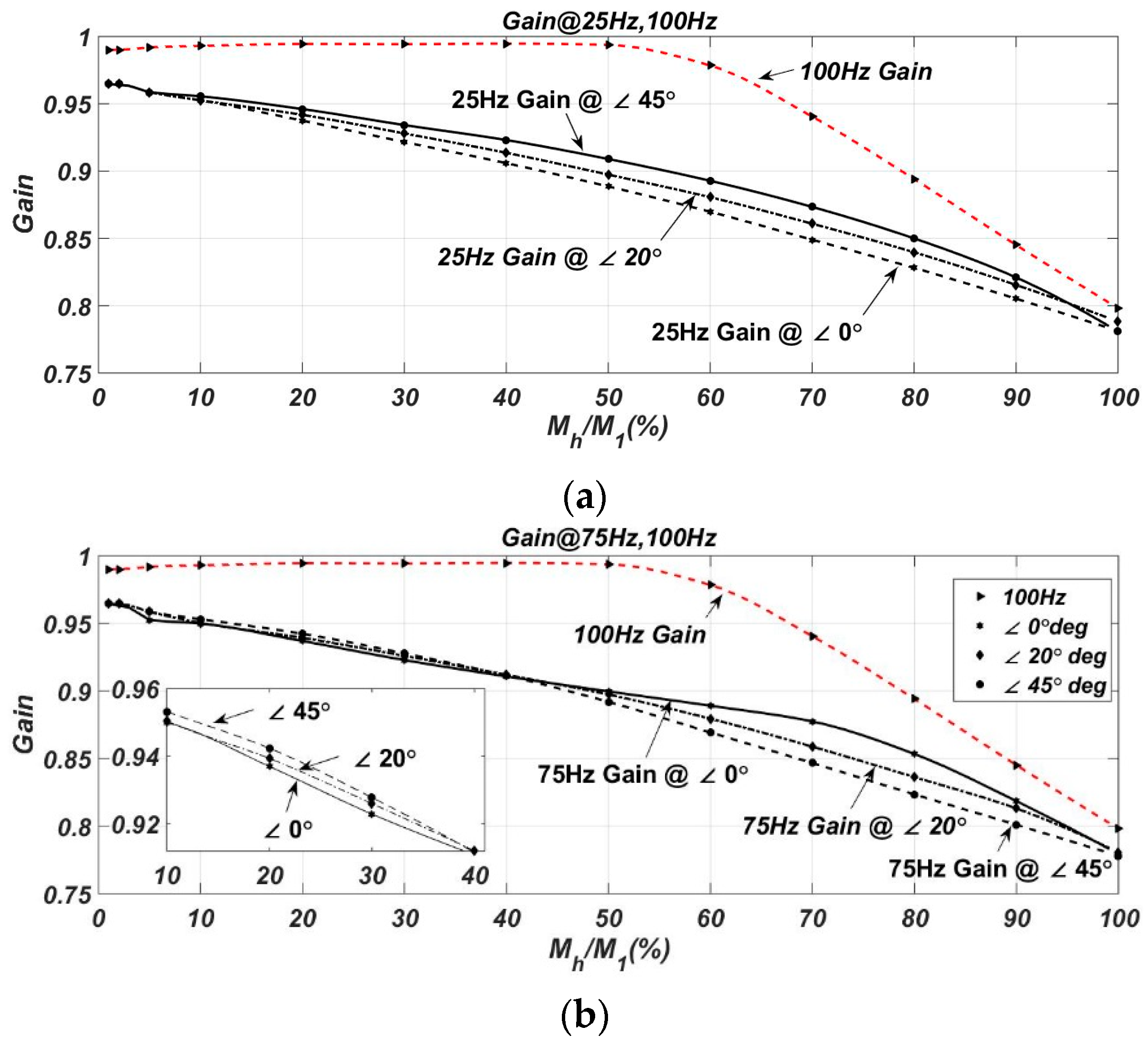
In the following Figures, voltage and current of the flyback microinverter (Figure 7) as well as the flyback Gain of 25, 75 and 100 Hz for three different injection levels (i.e., 4%, 6%, 8% (Figure 8a–c respectively), are presented. It should be noted that the Gain at 25 and 75 Hz were measured in an interval of 60 s, while the Gain at 100 Hz was measured only in a time instant which was used as FOM. Finally, in Figure 9 the Gain of 25 and 75 Hz injections at Mh/M1 = 8% are illustrated for three different angles (i.e., 0°, 20° and 45°), being in line with the simulations in Section 2.1.3.
According to Figure 8a–c the Gain at 25 and 75 Hz is affected by the sub/inter-harmonic injection but not significantly, since the distortion is negligible for the low injection levels, as the ones in the experimental test are. Therefore, the Gain at sub/inter-harmonic component with ratios Mh/M1 < 20% is in close match with FOM Gain, consisting them compatible with the Pdc-MICs. It should be noted that Mh/M1 ratios as high as 20% is higher than the usual injection levels, recommended for anti-islanding schemes in grid-connected PV-inverters (power quality requirements). Moreover, it should be mentioned that according to simulations and theoretical analysis the Gain at the sub/inter-harmonics should have been lower for the higher levels of injections, which does not apply in these experimental results. This is due to the fact that the Discrete Fourier Transformation (DFT), which was used to obtain the amplitude of the injected sub/inter-harmonic, has low accuracy for such small injection levels [4,6].
Finally, Figure 9 illustrates the experimental Gain as a ratio of FOM Gain at 25 and 75 Hz for three different angles a and Mh/M1 = 8%. The presented results are in accordance with the simulation ones, as for 45 degrees Gain is expected to present higher values, for both the 25 and the 75 Hz. Yet, the angle impact for such low Mh/M1 ratios (as the Mh/M1 = 8% is) is rather insignificant; according to Figure 9, the achieved improvement in Gain is barely 2%. Therefore, for small injections, as mentioned in previous sections, angle a does not have any decisive role in the injected component Gain. Nonetheless, for larger injections, current angle can be a useful tool for the Gain maximization.
2.2. Analysis of Sub/inter-harmonic and Harmonic Injection in Multiple Inverters
The effectiveness of anti-islanding schemes that are based on the injection of harmonic current components (either sub/inter-harmonics or integer multiples of fundamental frequency) dilutes when multiple inverters that utilize the same harmonic component are connected to the same node, as mentioned before in the introduction. In this work, in order to resolve this issue we propose a predefined delay Tγ in the harmonic injection of the inverters. This delay is applied with respect to the voltage at PCC (which is already sensed by PV-inverters) without requiring any kind of communication among the inverters (each inverter applies Tγ independently); hence no additional hardware or cost investment is required. In this work Tγ = 0 has been agreed among the inverters and is used for either sub/inter-harmonic or integer multiples integers of fundamental frequency injections.
The analysis following is based on this assumption (Tγ = 0). Moreover, the analysis is generic as it considers both the sub/inter-harmonics and the integer multiples of the fundamental frequency current components.
The instantaneous value of the injected current (both sub/inter-harmonic and integer multiples of fundamental frequency fall in the same category) is given by the following equation:
where Iinv,h[n] is the amplitude of the fundamental current component of n-inverter and φ[n] the angle of the n-Inverter current.
The sum of N-injections with h-frequency can be written as:
Equation (9) can be written in the following form as a phasor:
Considering that Tγ = 0, the injections may be delayed from each other for only specific time fractions of the fundamental period. Those are expressed by Δtd = qt[n]T1, where T1 is the fundamental period and qt[n] an integer number denoting how many fundamental cycles the injection of n-inverter lags the first inverter injection. In this context, the first inverter harmonic injection is considered as a reference and therefore qt[1] = 0 and φ[1] = 0. Therefore, the angle φ[n] denotes the phase difference between the nth and 1st inverter current components and is given by the following equation:
In this context, Equation (10) can be written as:
Therefore, the magnitude of the total injected current from Equation (10), which defines the total reduction of the injected current, is given by the following equation:
while the angle of the total injected current is given by:
Consequently, integer multiples of the fundamental frequency leads to zero phase angles between the injected harmonic components (irrespective of both the harmonic order and the qt[n] value); this is because when qt[n] and h are integer numbers, then the angle φ[n] will be always an integer multiple of 2π. Therefore, considering Equation (13) and that φ[1] = φ[n] = 2π = 0, it is also concluded that the cancellation/reduction effect in Iinv,h,sum is nullified, when integer multiples of the fundamental frequency are used.
In order to clarify this, Figure 10 is presented above, illustrating the total harmonic current Iinv,h,sum for two cases: (a) the inverters starts the injection without any agreement and (b) a common Τγ has been agreed.
On the other hand, the angle φ of sub/inter-harmonic current components might not be zero, since h is not an integer number and therefore 2qt[n]∙π∙h ≠ 2π. Consequently, this leads to the reduction (and occasionally to the cancelation) of the total amount of harmonic current component Iinv,h,sum. It is worth noting that the reduction depends upon both the frequency of the injected current and the fundamental cycle that the injection occurs, as it is stated in Equations (10)–(14).
As an example, the waveform of iinv,h,sum(t) that is produced by the sum-up of two inter-harmonic current components (70 Hz) at 1 pu (injected continuously by two inverters according to the above guidelines, Τγ = 0) is depicted in Figure 11, along with the corresponding PCC voltage and inter-harmonic current components waveforms. The first inverter performs an injection starting at the first fundamental period of vpcc·(qt[1] = 0), while the 2nd inverter performs an injection starting at the 2nd fundamental period (qt[2] = 1).
This results in a φ angle among the injected current components that leads to the reduction of the total injected component by 69.1%. It should be noted that in case of synchronized inverters injection, the total injected component would reach 2 pu; Iinv,h[1]pu = 1; Iinv,h[2]pu = Iinv,h [2]/Iinv,h [1]; Iinv,h,sumpu = (iinv,h[1] + iinv,h[2] + … + iinv,h[N])/Iinv,h [1].
Figure 12 illustrates the reduction at the total amount of harmonic current component Iinv,h,sum, in the case of two inverters (which are not synchronized) inject a harmonic current of various frequencies and qt[2]-values; sub/inter-harmonic as well as integer multiples of the fundamental frequency components are taken into consideration. The reduction at Iinv,h,sum is presented as a percentage of the maximum total injection that would occur if the injections were somehow synchronized. Frequency scanning was performed from 25 to 75 Hz, due to the fact that frequencies below 25 Hz are rarely used in practice and present practical implementation issues, while for frequencies above 75 Hz the graph of the injection reduction is repeated every line-period and therefore it is omitted. However, the graphs in Figure 12 apply to all frequencies above 25 Hz due to the fact that j (which is an integer number) can represent the omitted frequencies by setting its value appropriately e.g., setting j = 2 represents 100 Hz. According to Figure 12, the injection of sub/inter-harmonics current components may lead to a compromised harmonic current component Iinv,h,sum. As it has been earlier discussed, this reduction comes from the phase angle (φ ≠ 0) that is created among the inverters harmonic components. On the other hand, integer multiples of the fundamental frequency current components present zero phase difference and, thus, no reduction in the total harmonic injection is observed, irrespective of h, qt[n]. Based on the above stated facts, we conclude that in the case of asynchronous injection among the inverters, sub/inter harmonics are unsuitable due to the severe reduction on the total amount of harmonic component. In this context, using integer multiples with a common Tγ delay consists a much more attractive solution for the implementation of harmonic injection based anti-islanding schemes.
This analysis is useful in anti-islanding schemes, such as cross-correlation [6] and Goertzel [7] that evaluate the grid condition at PCC (grid-connected or islanded) in an indirect way, injecting sub/inter-harmonic or harmonic current components and measuring voltage response via their algorithms. This analysis for the aforementioned methods ensures that no reductions in the sub/inter-harmonic or harmonic injections will occur (in case of multiple inverters) by choosing the proper injection profile. In addition, this analysis is vital in methods that use both current and voltage of the inverter to estimate its operation (grid-connected or islanded), such as impedance measurement in specific frequency [4], because it guarantees that the measured impedance in islanded mode will be greater or equal to grid-connected one ensuring the islanding detection. A discussion regarding these issues can be found in Section 3.
2.2.1. Simulation Results
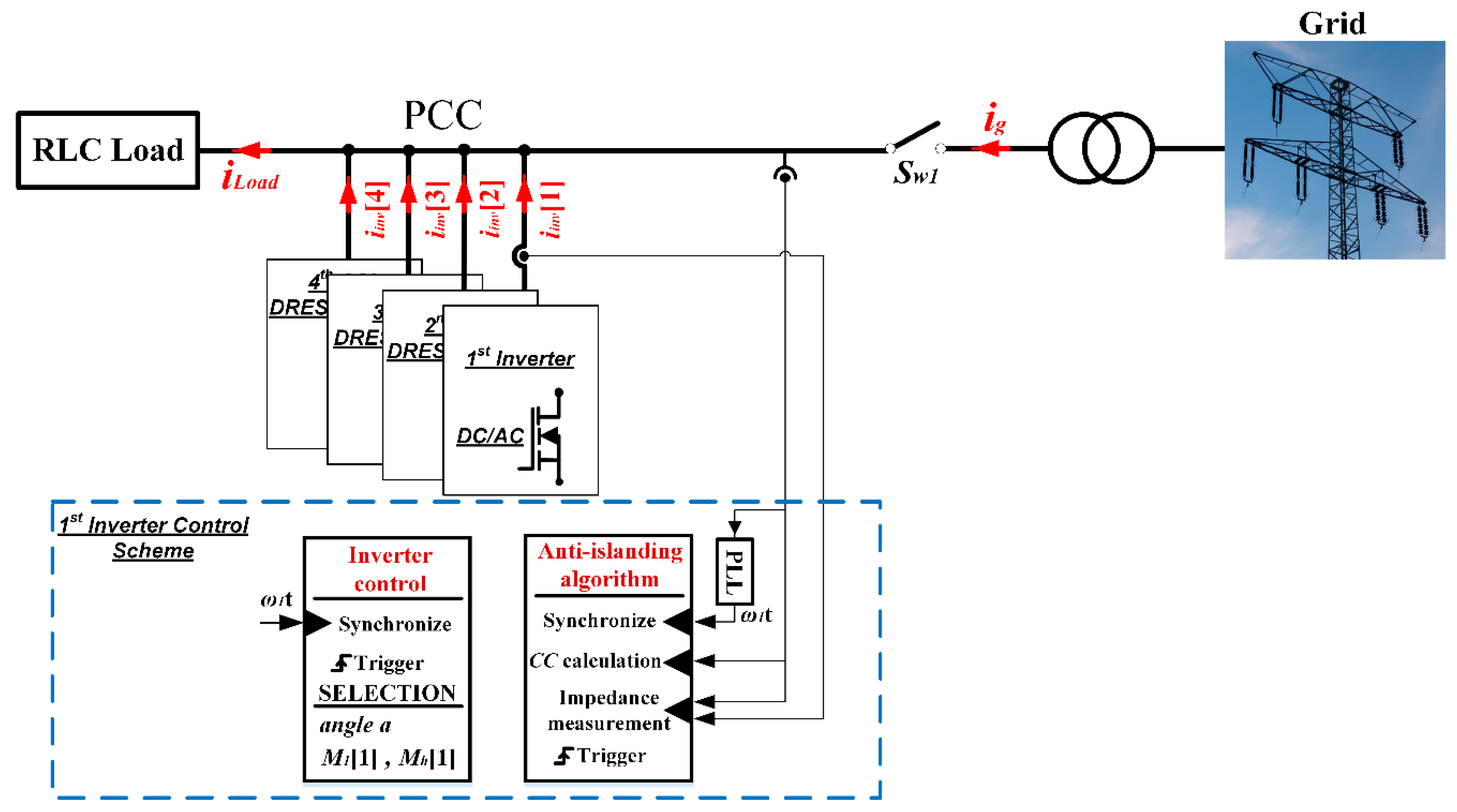
In this section an anti-islanding scheme that measures the inverter output stage impedance at 75 Hz as well as a modified version of the anti-islanding method in [6] are utilized, in order to demonstrate the cancellation effect that is caused by an inter-harmonic at 75 Hz; similar results would occur when inter-harmonic components of different frequency or sub-harmonic components are used. The simulation considers four PV-inverters (typical voltage-source inverters with unitary Gain value have been selected) and a RLC load according to IEEE 1547.1 recommended anti-islanding testing procedure, as depicted in Figure 13. The electrical characteristics of each inverter are summarized in Table 1, whereas a time delay Tγ = 0 has been agreed among the inverters, as it has been earlier proposed. The cancellation effect is meaningful during the grid-connected operation where the evaluation index (i.e., the impedance for the scheme in [4] and the cross-correlation index, (CC), for the scheme in [6]) of the anti-islanding scheme are expected to fall below the predefined threshold value (in general harmonic injection anti-islanding schemes identify a potential islanding condition when the evaluation index surpasses the predefined threshold). Therefore the following results have been taken considering the Sw1 switch is open and the system operates islanded. Finally, it should be clarified that PV-inverters (or any other inverter that it is connected to the grid) synchronize with the grid voltage (i.e., the PCC voltage in Figure 13). In this context, each inverter is capable of starting the injection at the beginning of the period of PCC voltage (Tγ = 0) without having to communicate with rest of inverters. However, this kind of synchronization does not imply that the inverters will start the injection at the same time. It does imply though, that the phase angle between the injections will have a limited impact, as long as h is an integer and a common delay Τγ is agreed.
It should be noted that according to the analysis conducted in Section 2.2 and the results in Figure 11, the anti-islanding schemes that measure the impedance at a specific frequency, are expected to overestimate the actual value of the impedance when the proposed common delay (Tγ) is applied. However, oversizing the measured impedance stands from the safe side of detecting the islanded operation. This is because the anti-islanding scheme identifies a potential islanding condition when the evaluation index surpasses the predefined threshold, as it has been previously discussed. Apparently, this may lead to a false tripping of the inverter during grid-connected operation of the PV-system. However, the actual value of the measured impedance is typically very low during grid-connected operation, therefore oversizing its value is unlikely (though not impossible) to make the inverter trip.
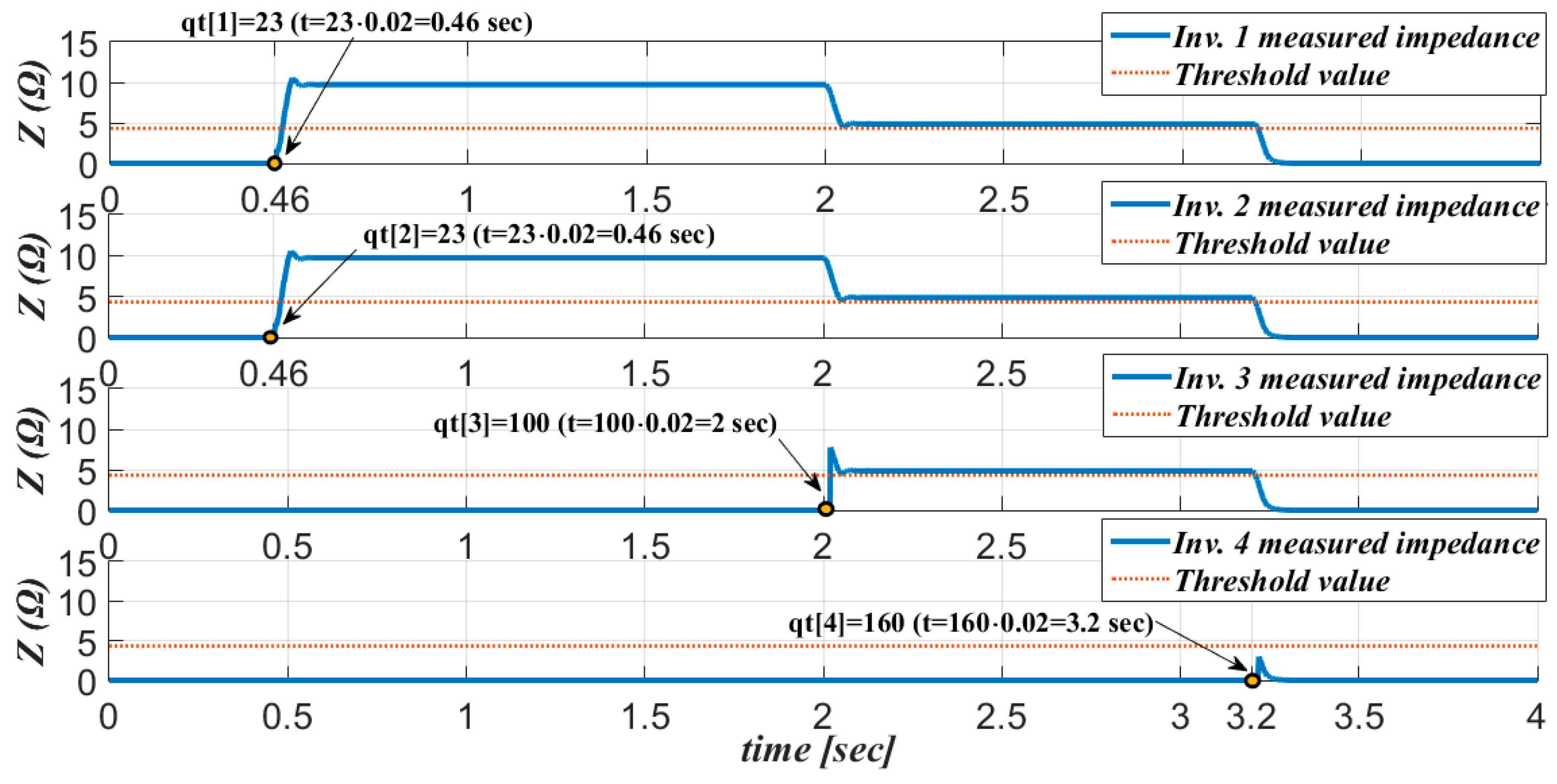
The time instances at which the inverters initiate the injection are shown in Figure 14. According to Figure 14, Inverters 1 & 2 initiate the injection at qt[1] = qt[2] = 23, Inverter 3 at qt[3] = 100, whereas Inverter 4 at qt[4] = 160. Based on the analysis conducted in Section 2.2, we conclude that (a) the injection of Inverters 1 & 2 will add up, (b) the injection of Inverters 3 & 4 will add up, and (c) the injection of inverters 1 & 2 and 3 & 4 will oppose. Therefore, considering equal magnitudes of the harmonic injection (as in Table 1), we expect the estimated impedance to become zero. Figure 15 is presented next illustrating the progression of harmonic cancellation among the inverters.
As it is clearly shown in Figure 15, the measured impedance (Z) of Inverters 1 & 2, although somewhat oversized as the impedance actual value has been 4 Ω, yet it is above the predefined threshold value. This is because Inverters 3 & 4 do not perform an injection and therefore no cancellation has occurred yet; therefore, Inverters 1 & 2 would successfully identify the islanded operation. At the time instant t = 2 s, Inverter 3 starts the injection. As it is clearly shown, this leads to a reduction on the estimated impedance (yet above the predefined threshold). Consequently, at the time instant t = 3.2 s, where the Inverter 4 starts the injection, the estimated impedance falls below the predefined threshold (approaching zero) due to the cancelation effect that it has been previously discussed.
The same remarks and observations as in the impedance measuring method can be made for the cross-correlation method (where CC in Figure 16 is the evaluation index of the cross-correlation method).
3. Discussion
In this work two significant issues regarding the utilization of sub/inter-harmonics for anti-islanding purposes have been reported and thoroughly analyzed. In particular, the first issue refers to the distortion effect of Pdc-MICs output current, whereas the second issue refers to the cancelation effect that is caused by the parallel operation of multiple inverters that inject the same order of harmonic current. As regards the distortion in Pdc-MICs, it has been proven to be insignificant due to the low magnitudes of the injected components that are typically used in anti-islanding schemes. However, although this effect is found to be insignificant, yet the presented mathematical model is of some value, as it can be used for various other applications that include harmonics. It is worth noting that its accuracy has been validated through theoretical, simulation (obtained through MATLAB and MATLAB/Simulink) as well as experimental results. As regards the second issue, it can be concluded that the cancellation effect among inverters of the same harmonic order component can be significant in the case of sub/inter-harmonics. It has been shown that when such harmonics are used asynchronously (i.e., when there is no communication among the inverters), then the equivalent induced voltage at PCC may drop to zero. On the other hand, when integer multiples of harmonics are utilized, then harmonic injection schemes might retain its effectiveness when all inverters initiate the injection at a predefined time delay (Tγ) with respect to the voltage at PCC. In this work Tγ = 0 has been agreed among the inverters. Nevertheless, Tγ could be agreed among the inverter manufacturers to any other value and could be included in the relevant prototyping standards. It should be noted that this inclusion does not require any kind of communication nor affects other methods that deal with issues of anti-islanding detection in multiple inverters. It should also be noted that in case of sub/inter-harmonics this strategy is meaningless as a phase-difference among the injected current components inevitably may be introduced irrespective of Tγ value. This has been validated by theoretical and simulation results. Therefore, the significant conclusion that is reached through this work is that sub/inter-harmonics (when are injected asynchronously or without communication) are unsuitable for anti-islanding purposes under the parallel operation of multiple inverters that inject current components of the same harmonic order. It should be noted that this cancelation effect is different from the cancellation effect that has been reported in [14], where harmonics are cancelled by the closed-loop current control of opposed inverters.
Finally, it should be noted that in the analysis above, we have assumed that the harmonic current components are injected continuously. However, anti-islanding schemes typically perform harmonic injections periodically (e.g., the anti-islanding schemes in [4,5,6,7]), in order to cope with power quality standards. In that way, the cancellation effect might be nullified as the harmonic current injection might be fully unsynchronized (an inverter injects the harmonic current when others do not). In fact such a strategy has been proposed in [13]. However, some kind of communication among the inverters is required, which increases cost and algorithm complexity, whereas it raises concerns regarding the method reliability (as it has been earlier discussed). Besides that, this technique could be applied only in the impedance measuring techniques, where both the induced voltage and the injected current are measured by the inverter, or alternatively in harmonic injection techniques which inject a fixed amount of harmonic component.
4. Materials and Methods
In this section the experimental test-bench that is used to evaluate the distortion of various frequencies is presented. Figure 17 illustrates the electrical equivalent of the test-bench, which consists of the flyback microinverter, the control scheme and the local load (switch Sw1 is considered open since all experimental tests are performed in islanded operation). The control scheme of the flyback microinverter consists a typical unitary DPF oriented scheme, where a modified signal is applied in the primary control, enabling the generation of sub/inter-harmonic current components as in [5]; in [5] the analysis, advantages and control of flyback microinverter are discussed extensively. Moreover, data acquisition and control scheme of flyback microinverter are implemented with the aid of dSpace MicroLabBox. It is noted that a DFT algorithm has been implemented through dSpace, in order to extract the harmonic current and voltage components from the inverter output current and PCC voltage, respectively. Finally, the foremost components used in flyback circuitry, as well as the electrical characteristics of flyback microinverter are presented in Table 2, along with grid and load specifications.
5. Conclusions
This work presents the theoretical background for the utilization of sub/inter-harmonic components for anti-islanding purposes and thoroughly discusses their limitations, particularly the ones that are caused by the parallel operation of multiple inverters. In addition, their implementation in the widely used category of PV Pdc-MICs inverters is discussed, focusing on the detailed analysis of the distortion effect that is caused in their output current by the injection of sub/inter-harmonic components. The main outcome of this work is that although sub/inter-harmonics seem to be an attractive solution for anti-islanding purposes without significant implementation issues in PV microinverters (the distortion that is caused by sub/inter-harmonics in PV Pdc-MICs is proven to be insignificant), they are proven to be unsuitable under the parallel operation of multiple inverters. This is due to the unavoidable cancellation effect that is observed when the same sub/inter-harmonic order component is injected asynchronously (injection is performed without communication among the inverters) by multiple inverters connected at the same node. In this context, a strategy is proposed in the current work that retains the effectiveness of the harmonic injection scheme under the injection of integer multiples of fundamental frequency. This strategy is based on setting the time delay parameter Tγ appropriately, within an agreed value range; such a technical regulation should be included in the relevant prototyping/operating standards of PV-inverters. Through this proposal, the cancellation effect is nullified when a harmonic order that is an integer multiple of the fundamental frequency is used. This is a rather important conclusion of the current work.
Author Contributions
Conceptualization, D.V.; Methodology, D.V. and F.V.; Software, D.V., F.V. and N.R.; Validation, D.V. and F.V.; Formal Analysis, D.V. and F.V.; Investigation, D.V. and F.V.; Resources, D.V., N.R. and F.V.; Data Curation, D.V., N.R. and F.V.; Writing-Original Draft Preparation, D.V. and N.P.; Writing-Review & Editing, D.V., N.R. and N.P.; Visualization, D.V. and N.P; Supervision, D.V. and N.P.
Funding
This research received no external funding.
Conflicts of Interest
The authors declare no conflict of interest.
References
- Ahmad, K.N.E.K.; Selvaraj, J.; Rahim, N.A. A review of the islanding detection methods in grid-connected PV inverters. Renew. Sustain. Energy Rev. 2013, 21, 756–766. [Google Scholar] [CrossRef]
- Bower, W.; Ropp, M. Evaluation of Islanding Detection Methods for Utility-Interactive Inverters in Photovoltaic Systems; Sandia Report No. 2002; Sandia National Laboratories: New Mexico, CA, USA, 2002. [Google Scholar] [CrossRef]
- Voglitsis, D.; Valsamas, F.; Rigogiannis, N.; Papanikolaou, N.; Kyritsis, A. Comparative study of active anti-islanding schemes compatible to MICs in the prospect of high penetration levels and weak grid conditions. IET Gener. Transm. Distrib. 2018. submitted for publication. [Google Scholar] [CrossRef]
- Asiminoaei, L.; Teodorescu, R.; Blaabjerg, F.; Borup, U. A digital controlled PV-inverter with grid impedance estimation for ENS detection. IEEE Trans. Power Electron. 2005, 20, 1480–1490. [Google Scholar] [CrossRef]
- Voglitsis, D.; Papanikolaou, N.; Kyritsis, A.C. Incorporation of harmonic injection in an interleaved flyback inverter for the implementation of an active anti-islanding technique. IEEE Trans. Power Electron. 2017, 32, 8526–8543. [Google Scholar] [CrossRef]
- Voglitsis, D.; Papanikolaou, N.P.; Kyritsis, A. Active Cross-Correlation Anti-Islanding Scheme for PV Module Integrated Converters in the Prospect of High Penetration Levels and Weak Grid Conditions. IEEE Trans. Power Electron. 2018. submitted for publication. [Google Scholar] [CrossRef]
- Kim, J.H.; Kim, J.G.; Ji, Y.H.; Jung, Y.C.; Won, C.Y. An islanding detection method for a grid-connected system based on the Goertzel algorithm. IEEE Trans. Power Electron. 2011, 26, 1049–1055. [Google Scholar] [CrossRef]
- Robert, A.; Deflandre, T.; Gunther, E.; Bergeron, R.; Emanuel, A.; Ferrante, A.; Finlay, G.S.; Gretsch, R.; Guarini, A.; Gutierrez Iglesias, J.L.; et al. Guide for Assessing the Network Harmonic Impedance. In Proceedings of the 14th International Conference and Exhibition on Electricity Distribution. Part 1. Contributions (IEE Conf. Publ. No. 438), Birmingham, UK, 2–5 June 1997. [Google Scholar] [CrossRef]
- Bae, B.Y.; Jeong, J.K.; Lee, J.H.; Han, B.M. Islanding detection method for inverter-based distributed generation systems using a signal cross-correlation scheme. J. Power Electron. 2010, 10, 762–768. [Google Scholar] [CrossRef]
- European Copper Institute. Voltage Characteristics of Electricity Supplied by Public Distribution Systems; Standard EN 50160:2010/A1; European Copper Institute: Brussels, Belgium, 2015. [Google Scholar]
- International Electrotechnical Commission. Photovoltaic (PV) Systems—Characteristics of the Utility Interface; IEC 61727 2004; International Electrotechnical Commission: Geneva, Switzerland, 2004. [Google Scholar]
- Briz, F.; Díaz-Reigosa, D.; Blanco, C.; Guerrero, J.M. Coordinated operation of parallel-connected inverters for active islanding detection using high frequency signal injection. IEEE Trans. Ind. Appl. 2014, 50, 3476–3484. [Google Scholar] [CrossRef]
- Timbus, A.V.; Teodorescu, R.; Blaabjerg, F.; Borup, U. Online Grid Impedance Measurement Suitable for Multiple PV Inverters Running in Parallel. In Proceedings of the 21st Annual IEEE Applied Power Electronics Conference and Exposition (APEC), Dallas, TX, USA, 19–23 March 2006. [Google Scholar] [CrossRef]
- Reigosa, D.; Briz, F.; Blanco, C.; Garcia, P.; Guerrero, J.M. Active islanding detection for multiple parallel-connected inverter-based distributed generators using high-frequency signal injection. IEEE Trans. Power Electron. 2014, 29, 1192–1199. [Google Scholar] [CrossRef]
- Bzura, J.J. The AC module: An overview and update on self-contained modular PV systems. In Proceedings of the IEEE PES General Meeting, Providence, RI, USA, 25–29 July 2010. [Google Scholar] [CrossRef]
- Gao, M.; Chen, M.; Zhang, C.; Qian, Z. Analysis and implementation of an improved flyback-inverter for photovoltaic AC module applications. IEEE Trans. Power Electron. 2014, 29, 3428–3444. [Google Scholar] [CrossRef]
- Li, Q.; Wolfs, P. A review of the single phase photovoltaic module integrated converter topologies with three different dc link configurations. IEEE Trans. Power Electron. 2008, 23, 1320–1333. [Google Scholar] [CrossRef]
- Xue, Y.; Chang, L.; Kjær, S.B.; Bordonau, J.; Shimizu, T. Topologies of single-phase inverters for small distributed power generators: An overview. IEEE Trans. Power Electron. 2004, 19, 1305–1314. [Google Scholar] [CrossRef]
- IEEE. Standard Conformance Test Procedures for Equipment Interconnecting Distributed Resources with Electric Power Systems; IEEE Std 1547.1 2005; IEEE: New York, NY, USA, 2005. [Google Scholar] [CrossRef]
- International Electrotechnical Commission. Utility-Interconnected Photovoltaic Inverters—Test Procedure of Islanding Prevention Measures; IEC Std. IEC 62116; International Electrotechnical Commission: Geneva, Switzerland, 2014. [Google Scholar]
Figure 1.
Block diagram of microinverter with pseudo dc-link (Pdc-MIC) with high frequency transformer.
Figure 1.
Block diagram of microinverter with pseudo dc-link (Pdc-MIC) with high frequency transformer.

Figure 2.
Demonstration of bypassing the unfolding H-Bridge of Pdc-MIC (a) 75 Hz inter-harmonic signal and the fundamental signal are bypassed; (b) 25 Hz sub-harmonic signal and the fundamental signal are bypassed.
Figure 2.
Demonstration of bypassing the unfolding H-Bridge of Pdc-MIC (a) 75 Hz inter-harmonic signal and the fundamental signal are bypassed; (b) 25 Hz sub-harmonic signal and the fundamental signal are bypassed.

Figure 3.
Demonstration of the distortion formation when (a1) 25 Hz sub-harmonic signal with a = 0° are bypassed; (a2) 25 Hz sub-harmonic signal with a = 60° are bypassed; (b1) 75 Hz inter-harmonic signal with a = 0° are bypassed and the fundamental signal; (b2) 75 Hz inter-harmonic signal with a = 60° are bypassed and the fundamental signal.

Figure 4.
Representation of a sinusoidal waveform by a 2nd-order Taylor Polynomial approximation (a) around 0; (b) around 3π/4.
Figure 4.
Representation of a sinusoidal waveform by a 2nd-order Taylor Polynomial approximation (a) around 0; (b) around 3π/4.
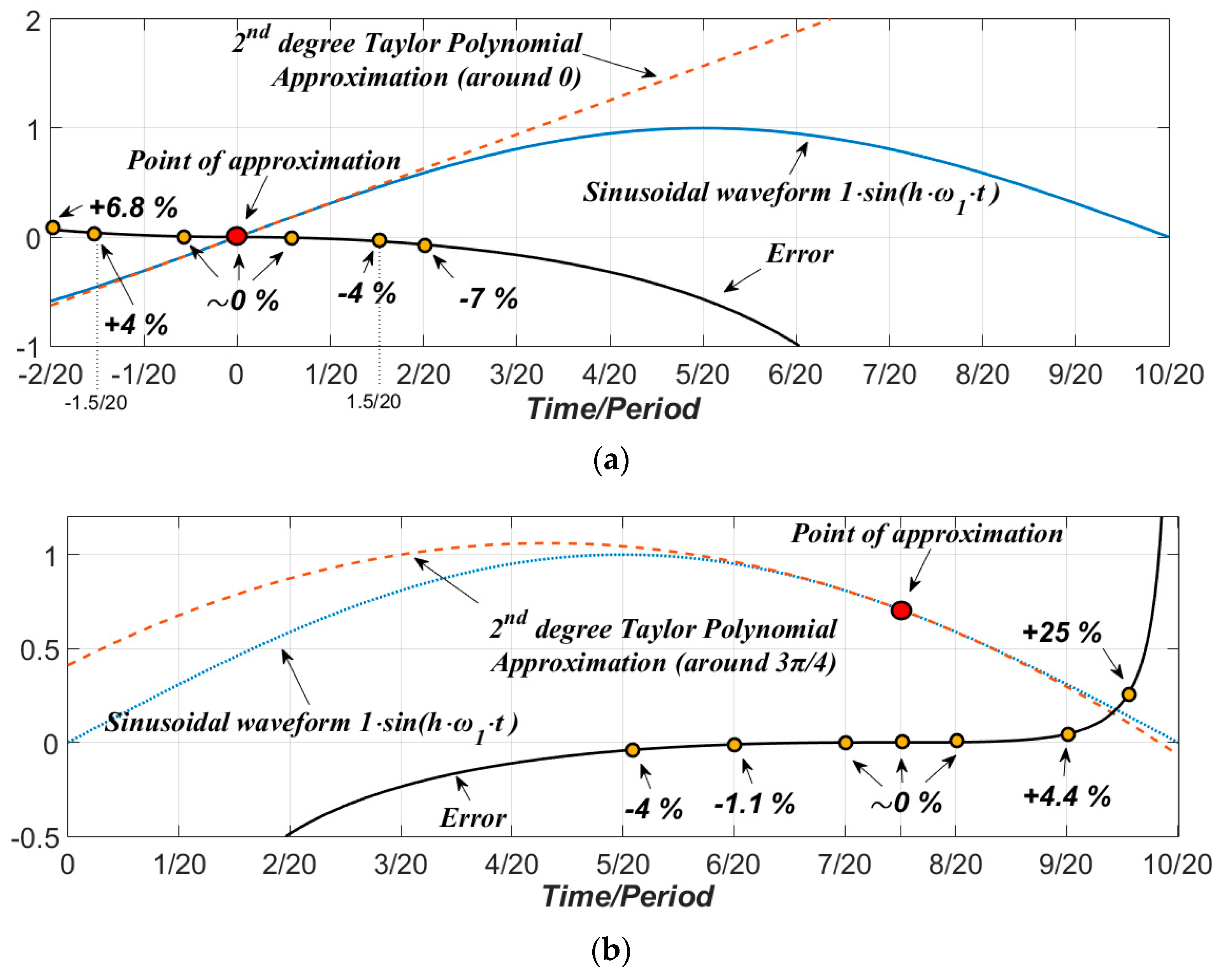
Figure 5.
THD of the 75 Hz modulation signal as a function of angle a (a) Mh/M1 = 10%; (b) Mh/M1 = 40%.
Figure 5.
THD of the 75 Hz modulation signal as a function of angle a (a) Mh/M1 = 10%; (b) Mh/M1 = 40%.
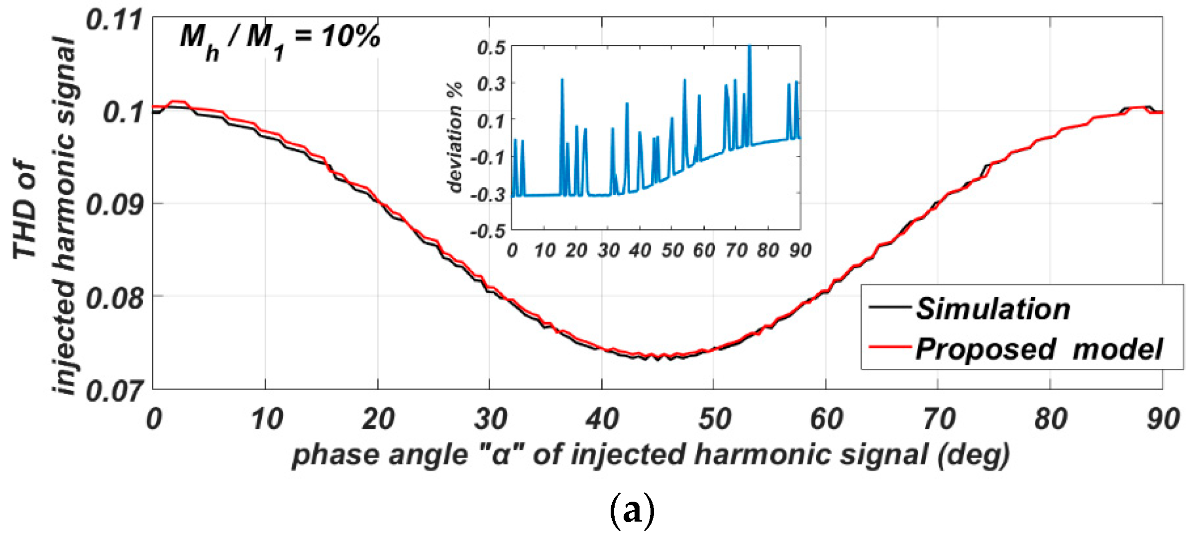

Figure 6.
Simulation: Pdc-MIC Gain as a function of Mh/M1 (a) Sub-harmonic injected current component at 25 Hz; (b) Inter-harmonic injected current component at 75 Hz.
Figure 6.
Simulation: Pdc-MIC Gain as a function of Mh/M1 (a) Sub-harmonic injected current component at 25 Hz; (b) Inter-harmonic injected current component at 75 Hz.

Figure 7.
Voltage and Current of a 300 W experimental Pdc-MIC inverter.

Figure 8.
Experimental Gain at 25, 75, 100 Hz for (a) 4%; (b) 6%; (c) 8% injection with 0 degrees angle.
Figure 8.
Experimental Gain at 25, 75, 100 Hz for (a) 4%; (b) 6%; (c) 8% injection with 0 degrees angle.

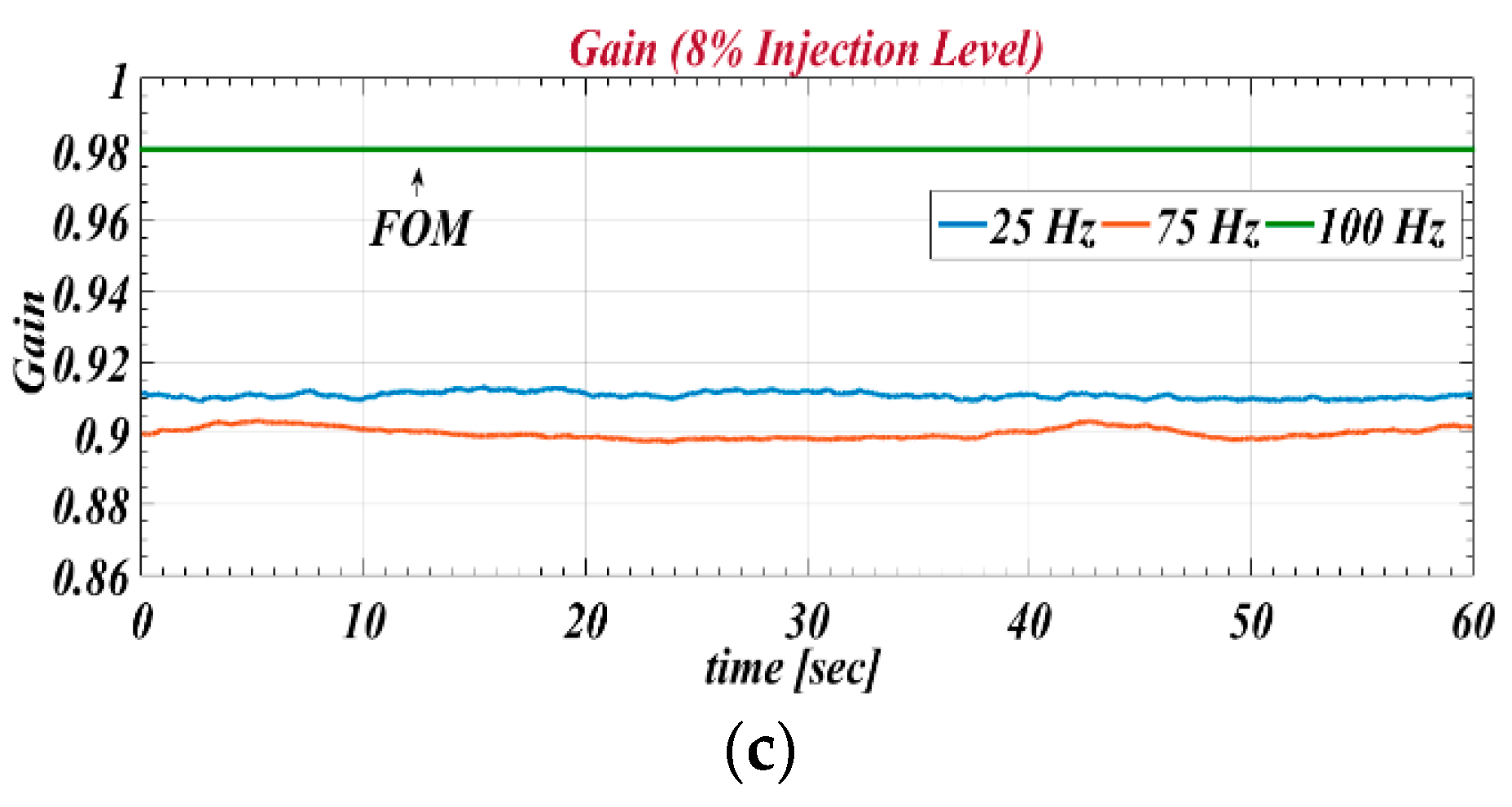
Figure 9.
Experimental Gain of a 300W Pdc-MIC; Mh/M1 = 8%.

Figure 10.
Iinv,h,sum coming from three current components of the same magnitude and frequency, where h is an integer and (a) no agreement has been made among the inverters (b) a common Tγ delay has been agreed among the inverters.
Figure 10.
Iinv,h,sum coming from three current components of the same magnitude and frequency, where h is an integer and (a) no agreement has been made among the inverters (b) a common Tγ delay has been agreed among the inverters.

Figure 11.
Two inverters inject continuously a current component at 70 Hz.

Figure 12.
Total harmonic reduction in case of two inverters for various qt[2] values along with the injected frequency.
Figure 12.
Total harmonic reduction in case of two inverters for various qt[2] values along with the injected frequency.
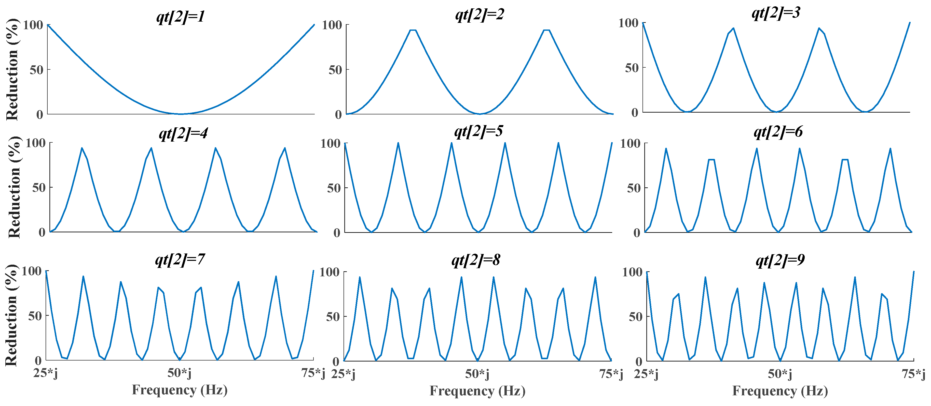
Figure 13.
Schematic of the simulated system.

Figure 14.
Harmonic current component (at 75 Hz) of inverters.

Figure 15.
Demonstration of cancellation effect among four inverters that utilize an impedance measuring scheme at 75 Hz.
Figure 15.
Demonstration of cancellation effect among four inverters that utilize an impedance measuring scheme at 75 Hz.

Figure 16.
Demonstration of cancellation effect among four inverters that utilize a modified version of the cross-correlation scheme of [6] (at 75 Hz).
Figure 16.
Demonstration of cancellation effect among four inverters that utilize a modified version of the cross-correlation scheme of [6] (at 75 Hz).

Figure 17.
Equivalent circuit of the experimental setup including the control scheme of the inverter.
Figure 17.
Equivalent circuit of the experimental setup including the control scheme of the inverter.


Table 1.
Electrical characteristics of simulated inverters.
| Description | Value |
|---|---|
| Inverter | (all the inverters have the same characteristics) |
| Output power per inverter | 500 W |
| Mh/M1 Iinv,1; Iinv,h | 8% 2.5 A; 0.2 A |
| Grid and load specifications | |
| Grid Rating | 141 Vrms/50 Hz |
| Local load R, L, C | 10 Ω, 12.5 mH, 795.77 μF |
| QF | 2.5 |
Table 2.
Foremost components and electrical characteristics of flyback micro-inverter.
| Description | Value |
|---|---|
| Interleaved flyback microinverter | |
| Output power | 300 W |
| DC input voltage (Vdc) | 30 V |
| Primary switches (S1, S2) | FCP260N60E |
| Secondary side diodes (D1, D2) | HFA15TB60 |
| H-bridge switches (SH1–4) | FCP260N60E |
| Transformer core | RM12 |
| Decoupling capacitor (C) | 2 mF |
| Primary inductance | 30 μH |
| Turns ratio | 1 |
| Leakage inductance | 0.42 μH |
| Filter inductance (Lf) | 950 μH |
| Filter capacitance (Cf) | 450 nF |
| Switching frequency (Primary Switches) | 20 kHz |
| Grid and load specifications | |
| Grid Rating | 90 Vrms ± 15%/50 Hz |
| Local load resistance | 235 Ω |
| Electrical equipment | |
| Controller | dSpace MicroLabBox |
| DC Input Voltage | Delta Electronica SM-3300 |
| DC power supply | TENMA 72-10495 |
© 2018 by the authors. Licensee MDPI, Basel, Switzerland. This article is an open access article distributed under the terms and conditions of the Creative Commons Attribution (CC BY) license (http://creativecommons.org/licenses/by/4.0/).
Share and Cite
MDPI and ACS Style
Voglitsis, D.; Valsamas, F.; Rigogiannis, N.; Papanikolaou, N. On the Injection of Sub/Inter-Harmonic Current Components for Active Anti-Islanding Purposes. Energies 2018, 11, 2183. https://doi.org/10.3390/en11092183
AMA Style
Voglitsis D, Valsamas F, Rigogiannis N, Papanikolaou N. On the Injection of Sub/Inter-Harmonic Current Components for Active Anti-Islanding Purposes. Energies. 2018; 11(9):2183. https://doi.org/10.3390/en11092183
Chicago/Turabian StyleVoglitsis, Dionisis, Fotis Valsamas, Nick Rigogiannis, and Nick Papanikolaou. 2018. "On the Injection of Sub/Inter-Harmonic Current Components for Active Anti-Islanding Purposes" Energies 11, no. 9: 2183. https://doi.org/10.3390/en11092183
Note that from the first issue of 2016, this journal uses article numbers instead of page numbers. See further details here.