Article

In Operando Neutron Radiography Analysis of a High-Temperature Polymer Electrolyte Fuel Cell Based on a Phosphoric Acid-Doped Polybenzimidazole Membrane Using the Hydrogen-Deuterium Contrast Method

1
IEK-3: Electrochemical Process Engineering, Institute of Energy and Climate Research, Forschungszentrum Jülich GmbH, 52425 Jülich, Germany
2
Institute of Materials Science and Technologies, Technische Universität Berlin, Hardenbergstr, 36, 10623 Berlin, Germany
3
Institute of Applied Materials, Helmholtz-Zentrum Berlin GmbH, Hahn-Meitner-Platz 1, 14109 Berlin, Germany
4
Faculty of Mechanical Engineering, RWTH Aachen University, 52062 Aachen, Germany
*
Author to whom correspondence should be addressed.
Energies 2018, 11(9), 2214; https://doi.org/10.3390/en11092214
Submission received: 26 July 2018 / Revised: 20 August 2018 / Accepted: 21 August 2018 / Published: 24 August 2018
(This article belongs to the Collection Electric and Hybrid Vehicles Collection)

Abstract

:
In order to characterize high temperature polymer electrolyte fuel cells (HT-PEFCs) in operando, neutron radiography imaging, in combination with the deuterium contrast method, was used to analyze the hydrogen distribution and proton exchange processes in operando. These measurements were then combined with the electrochemical impedance spectroscopy measurements. The cell was operated under different current densities and stoichiometries. Neutron images of the active area of the cell were captured in order to study the changeover times when the fuel supply was switched between hydrogen and deuterium, as well as to analyze the cell during steady state conditions. This work demonstrates that the changeover from proton to deuteron (and vice versa) leads to local varying media distributions in the electrolyte, independent of the overall exchange dynamics. A faster proton-to-deuteron exchange was re-discovered when switching the gas supply from H2 to D2 than that from D2 to H2. Furthermore, the D2 uptake and discharge were faster at a higher current density. Specifically, the changeover from H to D takes 5–6 min at 200 mA cm−2, 2–3 min at 400 mA cm−2 and 1–2 min at 600 mA cm−2. An effect on the transmittance changes is apparent when the stoichiometry changes.

1. Introduction

Climate change and environmental pollution are two of the most important challenges facing human civilization. Carrying advantages such as zero-carbon emissions and high energy conversion efficiency, polymer electrolyte fuel cells (PEFCs) are recognized as one alternative solution for future energy conversion technologies, and they have undergone substantial development in recent years [1]. Classical PEFCs, which are based on PFSA-type membranes (e.g., the well-known Nafion series membranes) and are operated between 60–90 °C, still have some issues that must be resolved, such as low carbon monoxide tolerance of the catalyst and complex water management. To overcome these, high temperature PEFCs, which are based on phosphoric acid-doped polybenzimidazole (PBI) membranes, with high operation temperatures between 140–180 °C, are the focus of current research [2,3,4].
In order to observe the transport phenomena or structural changes in a PEFC that operates at high temperature, some effective techniques have already been applied. For example, Maier et al. [5,6] used synchrotron X-ray radiography to perform phosphoric acid distribution and re-distribution inside MEAs (membrane electrode assemblies), which were considered as one of the first real in operando attempts within operating high temperature PEFCs. In these studies, the redistribution of the acid from the open cell voltage (OCV) condition, to the load condition was analyzed on the basis of the in-plane direction of the cell, with membrane expansions and contractions at the micrometer scale being explained by the hydration and dehydration of phosphoric acid in the membrane, which is highly affected by the water partial pressure within the cell. A few years later, in operando Raman spectroscopy in high temperature PEFCs was conducted by Majerus et al. [7]. In that work, a change of different acid concentrations was noted when current load changes occurred, which proved that Raman spectroscopy was a useful tool for investigating the relationship between phosphoric acid and polymer, as well as the chemical processes within the membrane under operating conditions. However, there have been no further reports of this measurement. In the meantime, a successful segmentation of the quantitative determination of phosphoric acid content and concentration in the gas diffusion layers of high temperature PEFC MEAs was first reported by using 3D X-ray tomographic microscopy images [8]. Moreover, in-operando electron paramagnetic resonance (EPR) is considered to be an appropriate method to investigate the chemical degradation mechanism of polymer electrolytes in fuel cells. The first attempt at using this technique in high temperature PEFCs was undertaken by Niemoeller et al. [9]. However, the electrochemical performance of the cell was not given.
In this manuscript, neutron radiography as a non-invasive and non-destructive method was utilized to characterize an in operando, high temperature PEFC, which has been widely used for the study of the water transport properties of classical PEFCs and direct methanol fuel cells [10,11,12,13,14,15]. Boillat et al. [16] first proved the potential of using neutron radiography for the analysis of phosphoric acid distribution in high temperature PEFCs. Recently, a joint study between the Helmholtz Center Berlin and the author’s research group monitored hydrogen diffusion by using hydrogen-deuterium contrast neutron imaging on an operating high temperature PEFC with five meander-shaped channels for the flow field and square active area (49 cm2) [17]. This revealed that the exchange rate from H-to-D is higher than that from D-to-H, and that the gas exchange time at the gas inlet is shorter than that at the gas outlet. However, it did not give the corresponding polarization analysis with H2 or D2 supplies.
In this work, a completely different cell set-up (which has well-defined gas transport properties in it, with more detailed information to be found in the section below) is used to analyze the hydrogen elements of the distribution and exchange process at different operating conditions of high temperature PEFCs with neutron radiography. Moreover, phosphoric acid re-distribution effects in the MEA will be discussed for changing the gas flow rates at the cathode.

2. Experimental

2.1. Cell Design and MEA Preparation

As is shown in Figure 1, a long cell with five straight parallel gas channels (for each channel, the size was width × depth × length = 0.1 cm × 0.1 cm × 21.5 cm) for the flow field and the active area was 21.5 cm2 (width × length = 1 cm × 21.5 cm) [18] was used for the presented measurements. By using this cell, the gas crossover under the bars between neighboring channels could be avoided, inducing well-defined gas transport properties in the cell. The cell was operated at a different current density (200 mA cm−2, 400 mA cm−2, and 600 mA cm−2) and stoichiometry (λan/ca = 2/2, 2/4 and 2/6). Its operating temperature was 160 °C and the pressure was ambient. In this work, dry gasses (dew point −40 °C) were supplied and the co-flow was used for all experiments.
The MEA used in this experiment was built in-house. The gas diffusion electrodes (GDEs) for the anode and cathode were identical and they were prepared by coating the Pt/C catalyst in non-woven carbon gas diffusion layers (GDLs, Freudenberg H23C4) by means of a doctor blade technique. The platinum loading of the electrodes was 1.00 ± 0.05 mg cm−2. A piece of poly-2.5-benzimidazole (PBI) membrane (FuMA-Tech, AM-55) was immersed in 85 wt % phosphoric acid at 110 °C for 18 h. After wiping off the phosphoric acid from the surface of the membrane, it contained a 15 ± 1 mg cm−2 phosphoric acid doping level and a thickness of 85 ± 2 µm. Then, all the components were assembled together, as shown in Figure 1, without a hot-press procedure. The MEA, with an active area of 21.5 cm2 (width × length = 1.0 cm × 21.5 cm), together with 300 µm-thick polymer gaskets made by polyfluoro alkoxy (PFA), was compressed by means of a torsional moment of 7 Nm between two graphitic flow fields and aluminum endplates, each of which was equipped with four heating cartridges. Before recording the polarization curve and performing the in-operando neutron radiography and impedance spectroscopy, a classical break-in procedure (the cell was operated at 200 mA cm−2 for 70 h) was carried out in advance. Detailed information regarding this break-in procedure can be found in [6]. Subsequently, the cell was used at the Helmholtz Center Berlin for in-operando neutron radiography.

2.2. Neutron Radiography Setup

Neutron radiographs were taken at the CONRAD2 beamline of the neutron source BER2 [19]. The neutron beam irradiated the cell in a through-plane direction, perpendicular to the membrane plane. All images were exposed for 0.5 s without a pause between the single exposures. A sCMOS camera (Andor “NEO”), in combination with a 20 µm-thick Gadox scintillator, was used with an optical magnification optic that resulted in a pixel size of 11 µm in each direction. More detailed information about this equipment can be found in other works [20]. The experimental setup of the in-operando neutron radiographic measurement of the cell is depicted in Figure 2. In this study, we used either hydrogen or deuterium as the anode reactant gas supply for the fuel cell’s operation in order to gain an imaging contrast for proton exchange processes. This method was already used in Arlt et al. [17], with the data analysis performed using ImageJ [21].

2.3. Mobile Single Cell Test Station

A mobile single cell test station was built at the Forschungszentrum Jülich with the electronic load ZS1806 (Höcherl & Hackl GmbH, Konzell, Germany) applied to monitor and control the operating condition of the cell. During the experiment with a neutron beam, the supplied anode gas was changed between H2 and D2 from time to time. To be more specific, the gas was switched between H2 and D2 every 30 min at 200 mA cm−2, every 20 min at 400 mA cm−2, and every 15 min at 600 mA cm−2.

2.4. Electrochemical Impedance Spectroscopy (EIS)

In this work, the impedance spectroscopy of the cell was measured by a Zahner Zennium electrochemical workstation (ZAHNER-Elektrik GmbH & Co. KG, Kronach, Germany), with an additional power booster for the high current application at the operating condition of 200 mA cm−2 and λan/ca = 2/2. The setup for the impedance spectroscopy measurements consisted of a conventional two-electrode setup, with the anode serving as a quasi-reference and the counter electrode and cathode working as a sense electrode. A frequency range of 10−1–105 Hz and an alternating current (AC) signal voltage amplitude of ± 10 mV was chosen. From the high frequency intercept of the EIS spectra with the real axis in the Nyquist plot (i.e., no phase shift between current and voltage), the ohmic resistance of the cell was given. For further details of the EIS experiments, see Wippermann et al. [22].

3. Results and Discussion

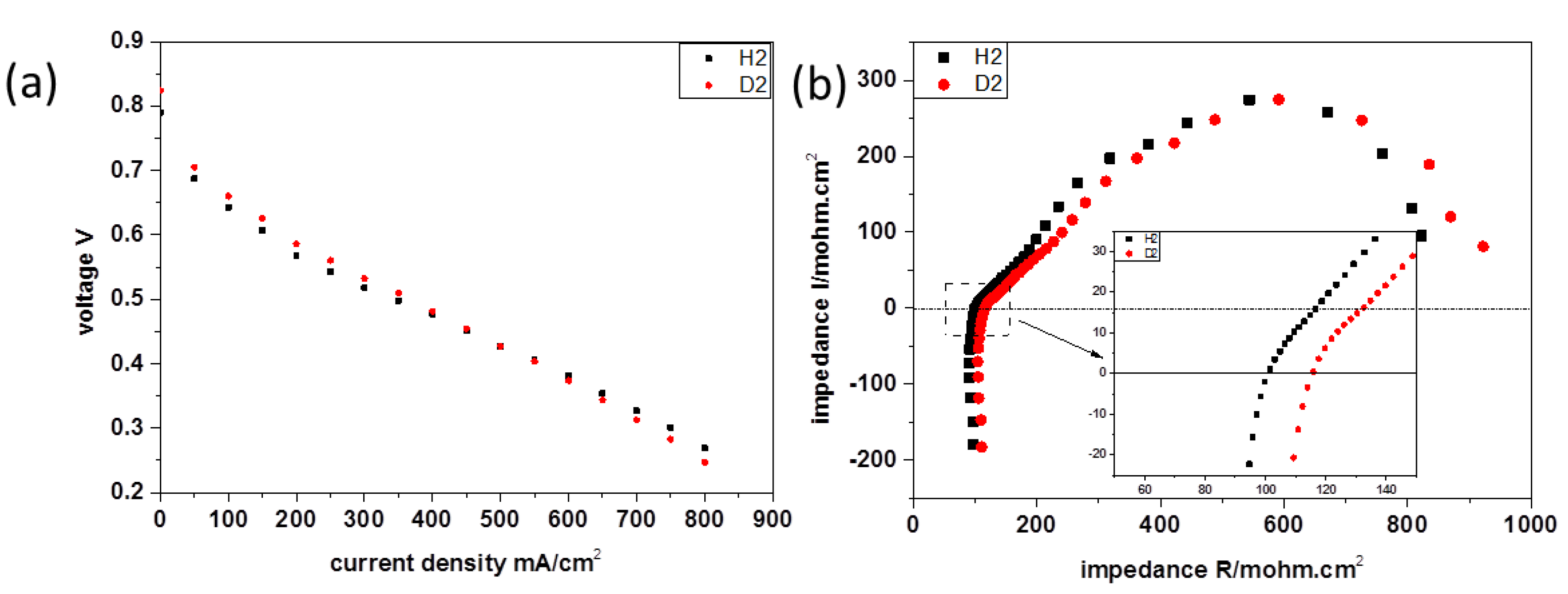
3.1. Cell Performance and Electrochemical Impedance Spectroscopy

3.1.1. Basic Electrochemical Theory

In order to explain the results of the cell performance with H2 or D2 operation, some basic electrochemical theory is given here. In general, the cell voltage can be calculated by the following Equation (1):
E c e l l = E N e r n s t R Ω j a c t t r a n s
where E c e l l is the cell voltage, E N e r n s t is the open cell voltage, R Ω is the ohmic resistance of the cell, j is the current of the cell, and a c t and t r a n s are the voltage loss by the activation and mass transport, respectively. At low current conditions, the voltage loss is mainly caused by the activation polarization. With the increasing current, the ohmic loss dominates and the mass transport limitations can be observed at very high current densities. In the visualization experiments presented here, the current density range spanned from 200 mA cm−2 to 600 mA cm−2. The mass transport losses did not play a major role, and they were neglected in further considerations (see Figure 3a for measured polarization curves) [23]. When the current (specifically, the current density j) is zero, the cell voltage corresponds to the open cell voltage. Furthermore, the theoretical open cell voltage can be calculated by the Nernst Equation:
E N e r n s t = E 0 R T 2 F ln X H 2 O X H 2 X O 2 0.5
where E0 is the standard voltage, R is the ideal gas constant, T is the cell temperature, F is the Faraday constant, and Xi (i represents H2O, H2 or O2) is the molar fraction of reactants and products in the gas phase.

3.1.2. Results and Discussion

In this experiment, the polarization curves of the cell were separately measured at λan/ca = 2/2, T= 160 °C for both hydrogen and deuterium as the anode gas supply. The results are shown in Figure 3a. The operating condition with deuterium gas showed a similar polarization curve to that with hydrogen as the gas supply. This is due to the isotopes (H and D) having very similar physical and chemical properties, which leads to fuel cells behaving in an almost identical manner. However, when the cell is in the low current density condition, its voltage with deuterium is higher than that of the cell with hydrogen, which is the converse in the high current density condition. In particular, at the open cell voltage (OCV), the voltage of the operating condition with deuterium is 0.034 V higher than that of the operating condition with hydrogen.
In Figure 3b, the impedance spectra were separately recorded for the cell at 200 mA cm−2 and 160 °C with H2 and D2. It can be seen that the ohmic resistance of the cell with H2 was about 101.65 mohm·cm2 and the value with D2 was roughly 115.80 mohm·cm2, which could be explained by the higher mass of D+ [17], leading to higher ohmic resistance.
Cell voltage changes independent of the operating conditions are shown in Figure 4. At 200 mA cm−2, the operating condition with deuterium shows a higher cell voltage, but at 600 mA cm−2 shows a lower voltage. Changes in the cell voltage at 400 mA cm−2 cannot be observed, and are essentially in good accordance with the polarization curves. Moreover, an additional increase of the cell voltage was noted after increasing the stoichiometry of the cathode, as expected.
In Figure 3a, it can be seen that the cell voltage with deuterium as the anode gas was 0.034 V higher than the voltage measured with hydrogen in the OCV condition. The standard potentials of the H2/ 1 2 O2 and D2/ 1 2 O2 reactions can be calculated with Equation (3):
E 0 = Δ G   n F
Where Δ G is the Gibbs free energy, F is the Faraday constant and n is the molar value of the transferred electrons (here, n = 2). The thermodynamic data and calculated standard voltages for 25 °C and atmospheric pressure are collected in Table 1 [24,25,26]. It can be seen that the standard potential of the D2/ 1 2 O2 reactions was always around 0.030 V higher than the potential of H2/ 1 2 O2 reactions, independent of the phase of the production, which was in good agreement with the measured OCV valves.
In the experiment, the cell temperature was kept at 160 °C and the molar fractions were the same for the H2/air and D2/air reactions. Thereby, comparing hydrogen with the deuterium condition, the value of the second item in Equation (2) is identical. Additionally, combined with Equations (1) and (2), and the EIS result shown above, the difference in the cell performance with H2 and D2 supplied could be explained as below. In the low current density range, the cell supplied with D2 had a higher voltage than that with H2 due to the higher standard potential of the D2/ 1 2 O2 reaction. With the increased current density, however, the effect of the ohmic resistance was magnified, which made the cell voltage of D2 lower than that of H2 at the higher current density.

3.2. Image Results and Discussion

As is shown in Figure 4, the anode gas supply was switched between H2 and D2 twice at different operating conditions of the cell. The second switchover was used to check the repeatability of the experiment, and thereby the reliability of the presented results. With the different attenuation coefficient of 2.972 cm−1 for natural ortho-phosphoric acid (H3PO4), 0.075 cm−1 for deuterated ortho-phosphoric acid (D3PO4), 2.182 cm−1 for natural pyro-phosphoric acid (H4P2O7), and 0.056 cm−1 for deuterated pyro-phosphoric acid (D4P2O7) [27], radiographs of the cell operated with H2 showed other transmittances than those of the cell while operating with D2. Using the Beer-Lambert law, the thickness of the phosphoric acid layer was calculated to 97.8 µm, which was in good agreement with the membrane thickness of 85 ± 2 µm, as measured before the cell assembly. The extra 10 µm phosphoric acid layer might indicate the phosphoric acid in the catalyst layer.
All neutron images displayed here were normalized with respect to a cell operating with H2. Consequently, areas where H+ was exchanged by D+, especially those that contain phosphoric acid or liquid water, were visible. The time signature shown in the radiographs represents the time interval between the moment of switching the anode gas at the 3-way valve and that of the radiograph’s exposure.

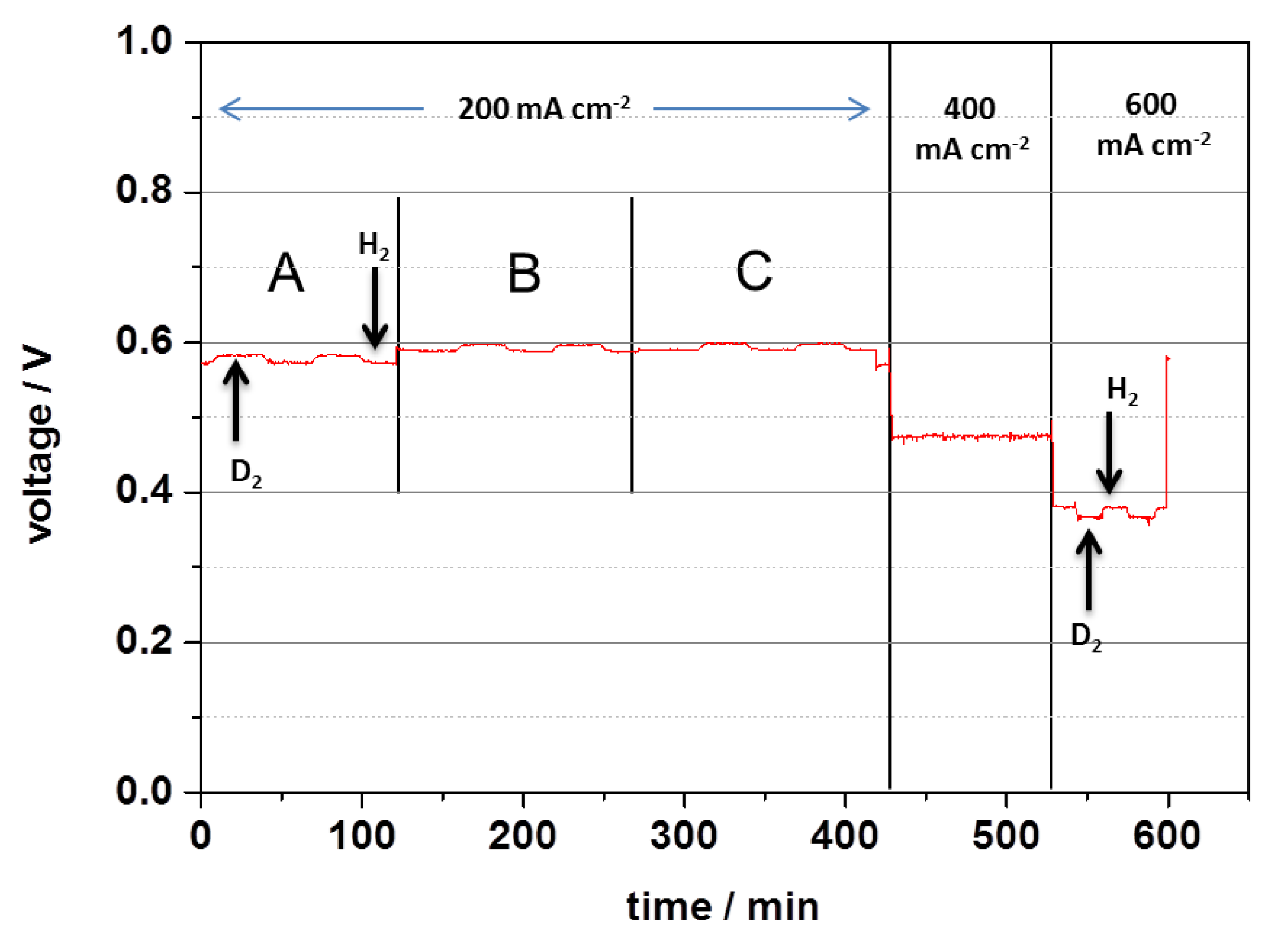
3.2.1. Overall H/D Exchange Process in the MEA

Figure 5 gives an overview of the impact of the changeover between H2 and D2 within the cell operating at 200 mA cm-2 and λan/ca = 2/2. The time shown in the first image of Figure 5a,b indicates that it took roughly 7 min for the anode gas to flow through the cell from the 3-way valve, which was dominated by the gas flow rate and the length and diameter of the gas tube. In Figure 5a, from top to bottom, it was observed that the exchange of H-to-D (images getting brighter) occurred along the gas orientation (from right to left) gradually. After 5 min, the changeover from H-to-D almost finished. In contrast, 5 min after the first visible effects due to the exchange of D-to-H (shown in Figure 5b), some parts of the active area were still brighter than the non-active area, which implies that there remained some deuterium in the MEA. Furthermore, simultaneous changes in the cell voltage (Figure 5c,d) could be observed, which also indicated the exchange time of H-to-D and D-to-H. In general, the H-to-D exchange proceeded faster (5–6 min) than the D-to-H exchange (7–8 min). Additionally, in some previous work [17], the cell performance was poor and the H/D exchange time was short (time of H-to-D exchange process was 108–138s; the time of the D-to-H exchange process was 144–174 s), which could be explained by the lower phosphoric acid content (up to 70 µm of the phosphoric acid layer) in the cell.
To explain the faster exchange process from H-to-D, ion transport mechanisms inside the phosphoric acid-doped PBI membrane are considered. Additionally, previous studies [3,28] have revealed that phosphoric acid within the membrane acts as the main proton conductor. Two types of proton transport mechanisms in phosphoric acid were recognized [29,30,31,32,33]: (1) the vehicular mechanism, which means that a proton is transported by a phosphoric acid molecule (vehicle); (2) the Grotthuss mechanism, which demonstrates that a proton hops through different phosphoric acid molecules. However, in the case of the vehicular mechanism, the exchange process between H and D should have no obvious difference because of the small change in the total mass of the phosphoric acid molecule (vehicle). Thus, the Grotthuss mechanism should mainly be considered for the description of the proton transport inside the phosphoric acid-doped PBI membrane.
In order to quantitatively explain the different exchange time of H-to-D and D-to-H, a model of proton transport was built based on the Grotthuss mechanism. First of all, only the phosphoric acid molecules were assumed to be the ion accepters and donors. Taking the exchange process of H-to-D as an example, we assumed that there were three steps of the substitution of a proton by a deuteron in a phosphoric acid molecule: (step 1) the molecule of the H3PO4 accepted a deuteron and donated a proton simultaneously; (step 2) the molecule of the DH2PO4 accepted a deuteron and donated a proton simultaneously; (step 3) the molecule of D2HPO4 accepted a deuteron and donated a proton simultaneously. For step 1, the efficiency of the substitution of a proton by a deuteron should be 100%. However, for steps 2 and 3, the efficiencies of the substitution were no longer 100%, because the deuterons in the molecule may also be substituted by the deuteron, which had no contribution for the exchange process of H-to-D. Without taking the isotope effect into account, the efficiencies of the substitution for steps 2 and 3 should be 2/3 and 1/3 respectively. Therefore, based on the operating current (200 mA cm−2), the phosphoric acid amount (assuming the ~15 mg cm−2 of phosphoric acid is pure H3PO4) in the MEA, and the efficiencies of the substitution for each step, it takes 6.75 min for all protons to be substituted by deuterons statistically (for steps 1, 2, and 3, the time is 1.23 min, 1.84 min, and 3.68 min respectively). However, due to the isotope effect, the activation energy of deuteron transport is higher than that of proton transport, which has been reported in [34,35,36,37,38]. Additionally, the lower conductivity of deuteron transport compared to proton transport has been proven in previous tests (Figure 3). Therefore, in a phosphoric acid molecule where protons and deuterons coexist, a proton has a higher probability of being ionized than a deuteron does, which makes the efficiency values of the substitution for steps 2 and 3 higher than 2/3 and 1/3, respectively. Subsequently, the time (as a measured value of 5–6 min) for all protons substituted by deuterons is shorter than the time (6.75 min) spent when the isotope effect is not taken into account. Similarly, when considering the exchange process of D-to-H, the efficiency of the substitution of a deuteron by a proton for step 1 should still be 100%. However, for steps 2 and 3, the efficiencies of the substitution should be lower than 2/3 and 1/3, respectively. Consequently, the time for all deuterons substituted by protons should be longer than 6.75 min, which was measured as 7–8 min.
This model can explain the different exchange times of H-to-D and D-to-H processes based on the hopping mechanism. In the future, the conductivities of natural phosphoric acid and deuterated phosphoric acid will be measured ex-situ at a high temperature (up to 180 °C), and the activation energies of proton and deuteron transport should be calculated separately, in order to make this model more accurate.

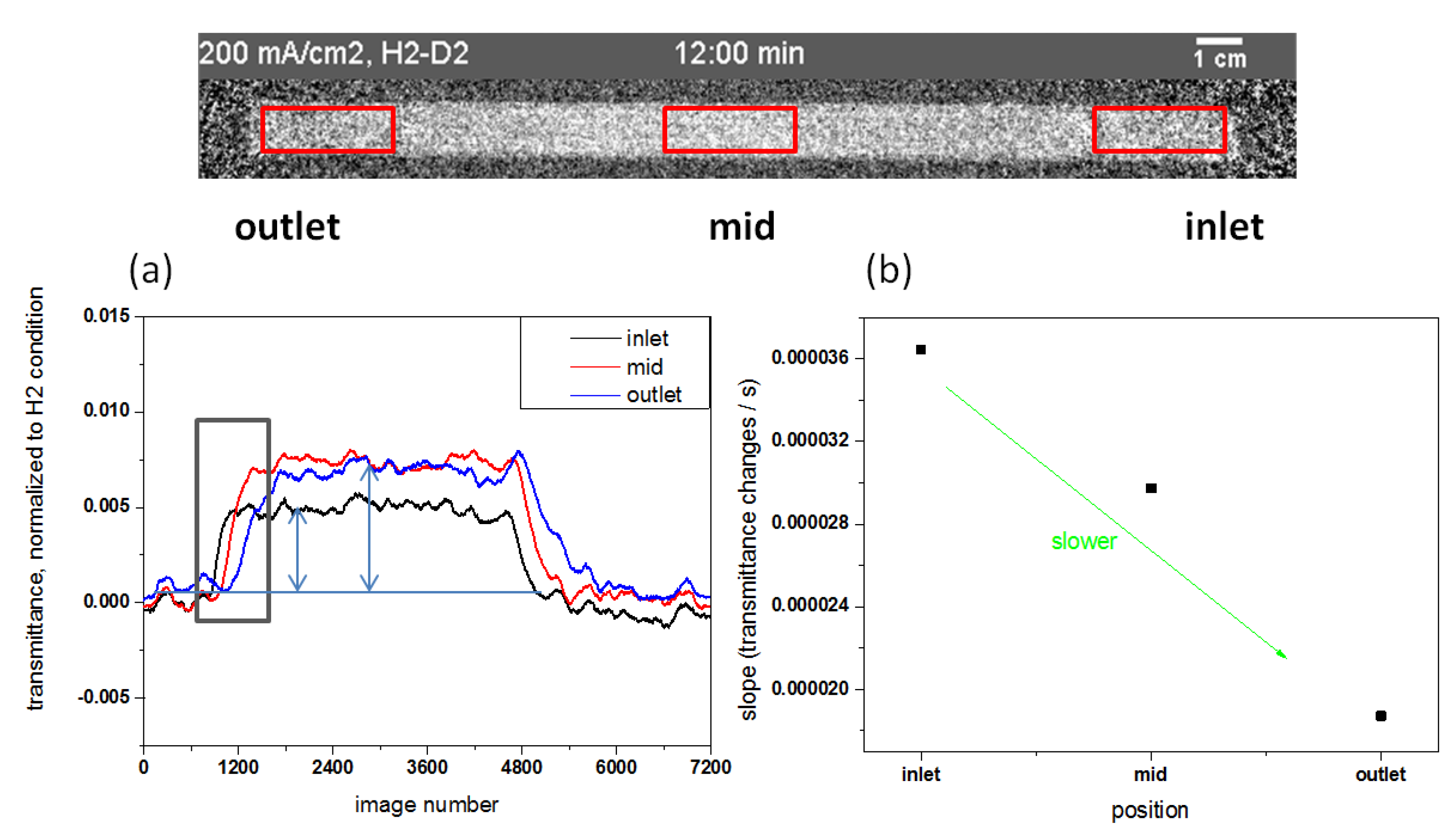
3.2.2. Local H/D Exchange Process of MEA

Figure 6a shows the temporal evolution of the transmittance changes at the gas inlet region, the mid part of the active area, and the gas outlet region. Figure 6b indicates that the transmittance change rate of the H-to-D exchange process decreases with the gas orientation. This might be caused by the different local concentrations of D2 gas in the channel. During the exchange, the gas in the flow channel should be a mix of H2 and D2, since there is no clear boundary between the different phases. Thus, there should be a D2 gas concentration gradient (highest concentration at the inlet part and lowest concentration at the outlet part) on the anode side during the exchange. Because of the similar chemical properties of isotopes, the rate of the electrochemical reduction reactions of H2→2H+ + 2e and D2→2D+ + 2e are assumed to be the same. Therefore, the higher D2 concentration lead to a larger amount of D+ ions as the charge carrier, which means that the total probability of deuteron transfer is higher at the gas inlet region than at the gas outlet region and further implies a relatively higher transmittance change rate.
It should be noted that the transmittance change due to H2 operation and D2 operation at the gas inlet region is smaller than at the gas outlet region (Figure 6a), which may primarily indicate the phosphoric acid redistribution with the MEA at the in-plane dimension. Due to the water vapor partial pressure gradient along the channel (increasing from the inlet to the outlet) [39], it may cause the hydration and dehydration of phosphoric acid at the outlet and inlet, respectively, which leads to fewer hydrogen elements at the inlet region, which may also induce the molecular redistribution of phosphoric acid from the gas inlet region to the outlet region. However, the water vapor’s partial pressure gradient might not be the only reason for the difference in this case. Some other factors could also be considered, such as the local temperature distribution, which influences the present material system (mainly water, phosphoric acid, diphosphate and membrane) of the phosphoric acid system and the PBI polymer redistribution, which is recognized to probably be partly deuterated during the exchange. Furthermore, all the factors mentioned above would make contributions to a local current distribution, which is expected to be simultaneously measured in future work in order to provide additional information for this scenario.

3.2.3. Impact of Different Current Densities on the H/D Exchange Process in the MEA

To investigate the influence of current density on the proton exchange rate, radiographs and transmittance changes of the cell operated at 200 mA cm−2, 400 mA cm−2, 600 mA cm−2, and λan/ca = 2/2 were exhibited for the H-to-D exchange (see Figure 7). This clearly reveals a faster D2 uptake for the higher current density of the cell, indicating that the current of the cell has a significant effect on the H/D exchange rate because of a higher amount of charge carrier that is transferred over the same time period at a higher current density. Additionally, we noted the exchange times at 200 mA cm−2, 400 mA cm−2, and 600 mA cm−2 to be 5–6 min, 2–3 min, and 1–2 min, respectively, which demonstrates an inversely proportional relationship.

3.2.4. Transmittance Changes Independent of Different Gas Flow Rates at the Cathode

Figure 8 shows the transmittance of the whole active area of the cell over time at 200 mA cm−2. During this, the anode gas was switched between H2 and D2 several times, and the stoichiometry was set to λan/ca = 2/2, λan/ca = 2/4, and λan/ca = 2/6. The lower level of transmittance represents the H2 operating condition, while the higher level of transmittance represents the D2 operating condition. With the increase in the stoichiometry of air at the cathode side, the transmittance of the whole active area of the cell with H2 operation remained almost stable, but with the D2 operation decreased. One possible explanation for this is that phosphoric acid redistribution took place in parallel to the membrane plane on the cathode side. It is well established in the literature [5,40] and also demonstrated by the calculation of the thickness of the phosphoric acid layer in the previous Section 3.2, that some quantity of phosphoric acid exists in the catalyst layer during cell operation. After increasing the stoichiometry, the higher flow rate of dry gas would dehydrate the MEA. In the meantime, the membrane sucks phosphoric acid from the catalyst layer in order to fill the voids generated by losing water. However, due to the high viscosity of concentrated phosphoric acid, some acid could not move and then it forms a neck-type phosphoric acid path. Ultimately, the acid path disconnects at the neck part and generates an isolated phosphoric acid droplet for charge transfer in the catalyst layer. Furthermore, it is worth noting that we always changed the stoichiometry during H2 operation. This means that the isolated phosphoric acid droplet was protonated. Then, after switching the anode gas to D2 at a higher cathode gas flow rate, deuterons are difficult to transport to the isolated phosphoric acid in order to replace the protons in that droplet, which further decreases the transmittance of D2 operation. Additionally, this isolated and protonated phosphoric acid had no influence on transmittance with H2 operation. In the future, to check the reliability of this hypothesis, a converse experiment (increasing the stoichiometry of air under D2 operation) is proposed to see if a similar result can be obtained.

4. Conclusions

A high temperature polymer electrolyte fuel cell based on a phosphoric acid-doped PBI membrane with five straight long gas channels on a flow field was investigated under different operating conditions by neutron radiography using the deuterium contrast method. We confirmed that the uptake of deuterium is faster than its discharge of deuterium under the same condition. This may be due to the different activation energies of proton and deuteron transport. Furthermore, the exchange rate of H and D is decreased from the gas inlet to the outlet, which is explained by the concentration gradient of the gas, and it consists of the elements that must be replaced. In addition, an inversely proportional relationship might exist between the exchange time and the current density. Finally, the gas flow rate might have some effects on the phosphoric acid distribution in the catalyst layer.
In the future, more work must be performed, such as on the conductivities of natural phosphoric acid and deuterated phosphoric acid at high temperature (up to 180 °C), simultaneous local current distribution measurement, local temperature distribution measurements, and changing the stoichiometry of air under D2 operation.

Author Contributions

T.A., Y.L., and N.K. assisted and performed the experimental part as well as the normalization and analyzation of the data and contributed to correlated parts of the paper; I.M. helped experimental design and data analyzation; W.L. supervised this work and reviewed and edited the manuscript.

Funding

This research was funded by China Scholarship Council 201406950052. And the APC was funded by central library of Forschungszentrum Jülich GmbH.

Acknowledgments

This work was supported by funding from the China Scholarship Council. We would like to thank Uwe Reimer and Wiebke Lüke for fruitful discussions. Technical support from Birgit Schumacher is also gratefully acknowledged.

Conflicts of Interest

The authors declare no conflict of interest.

References

  1. Zaidi, S.J.; Rauf, M.A. Fuel Cell Fundamentals; Springer: New York, NY, USA, 2009; pp. 1–5. [Google Scholar]
  2. Wannek, C.; Konradi, I.; Mergel, J.; Lehnert, W. Redistribution of phosphoric acid in membrane electrode assemblies for high-temperature polymer electrolyte fuel cells. Int. J. Hydrogen Energy 2009, 34, 9479–9485. [Google Scholar] [CrossRef]
  3. Li, Q.; Jensen, J.O.; Savinell, R.F.; Bjerrum, N.J. High temperature proton exchange membranes based on polybenzimidazoles for fuel cells. Prog. Polym. Sci. 2009, 34, 449–477. [Google Scholar] [CrossRef] [Green Version]
  4. Wainright, J.S.; Wang, J.T.; Weng, D.; Savinell, R.F.; Litt, M. Acid-doped polybenzimidazoles: A new polymer electrolyte. J. Electrochem. Soc. 1995, 142, 121–123. [Google Scholar] [CrossRef]
  5. Maier, W.; Arlt, T.; Wannek, C.; Manke, I.; Riesemeier, H.; Krüger, P.; Scholta, J.; Lehnert, W.; Banhart, J.; Stolten, D. In-situ synchrotron X-ray radiography on high temperature polymer electrolyte fuel cells. Electrochem. Commun. 2010, 12, 1436–1438. [Google Scholar] [CrossRef]
  6. Maier, W.; Arlt, T.; Wippermann, K.; Wannek, C.; Manke, I.; Lehnert, W.; Stolten, D. Correlation of synchrotron X-ray radiography and electrochemical impedance spectroscopy for the investigation of ht-pefcs. J. Electrochem. Soc. 2012, 159, F398–F404. [Google Scholar] [CrossRef]
  7. Majerus, A.; Labus, M.; Korte, C.; Bettermann, H.; Lehnert, W. In situ Raman spectroscopy on HT-PEM fuel cell. In Proceedings of the 4th European PEFC & H2 Forum, The European Fuel Cell Forum, Lucerne, Switzerland, 2–5 July 2013. [Google Scholar]
  8. Eberhardt, S.H.; Büchi, F.N.; Schmidt, T.J. Localization of Phosphoric Acid in HT-PEFCs by X-ray Tomographic Microscopy. In Proceedings of the 4th European PEFC & H2 Forum, The European Fuel Cell Forum, Lucerne, Switzerland, 2–5 July 2013. [Google Scholar]
  9. Niemöller, A.; Jakes, P.; Kayser, S.; Lin, Y.; Lehnert, W.; Granwehr, J. 3d printed sample holder for in-operando epr spectroscopy on high temperature polymer electrolyte fuel cells. J. Magn. Reson. 2016, 269, 157–161. [Google Scholar] [CrossRef] [PubMed]
  10. Boillat, P.; Scherer, G.G.; Wokaun, A.; Frei, G.; Lehmann, E.H. Transient observation of 2h labeled species in an operating pefc using neutron radiography. Electrochem. Commun. 2008, 10, 1311–1314. [Google Scholar] [CrossRef]
  11. Hartnig, C.; Manke, I.; Kardjilov, N.; Hilger, A.; Grünerbel, M.; Kaczerowski, J.; Banhart, J.; Lehnert, W. Combined neutron radiography and locally resolved current density measurements of operating pem fuel cells. J. Power Sources 2008, 176, 452–459. [Google Scholar] [CrossRef]
  12. Cho, K.T.; Mench, M.M. Investigation of the role of the micro-porous layer in polymer electrolyte fuel cells with hydrogen deuterium contrast neutron radiography. Phys. Chem. Chem. Phys. 2012, 14, 4296. [Google Scholar] [CrossRef] [PubMed]
  13. Putra, A.; Iwase, H.; Yamaguchi, D.; Koizumi, S.; Maekawa, Y.; Matsubayashi, M.; Hashimoto, T. In-situ observation of dynamic water behavior in polymer electrolyte fuel cell by combined method of small-angle neutron scattering and neutron radiography. J. Phys. Conf. Ser. 2010, 247, 012044. [Google Scholar] [CrossRef]
  14. Manke, I.; Hartnig, C.; Kardjilov, N.; Messerschmidt, M.; Hilger, A.; Strobl, M.; Lehnert, W.; Banhart, J. Characterization of water exchange and two-phase flow in porous gas diffusion materials by hydrogen-deuterium contrast neutron radiography. Appl. Phys. Lett. 2008, 92, 244101. [Google Scholar] [CrossRef] [Green Version]
  15. Schröder, A.; Wippermann, K.; Lehnert, W.; Stolten, D.; Sanders, T.; Baumhöfer, T.; Kardjilov, N.; Hilger, A.; Banhart, J.; Manke, I. The influence of gas diffusion layer wettability on direct methanol fuel cell performance: a combined local current distribution and high resolution neutron radiography study. J. Power Sources 2010, 195, 4765–4771. [Google Scholar] [CrossRef]
  16. Boillat, P.; Biesdorf, J.; Oberholzer, P.; Kaestner, A.; Schmidt, T.J. Evaluation of Neutron Imaging for Measuring Phosphoric Acid Distribution in High Temperature PEFCs. J. Electrochem. Soc. 2014, 161, F192–F198. [Google Scholar] [CrossRef]
  17. Arlt, T.; Lüke, W.; Kardjilov, N.; Banhart, J.; Lehnert, W.; Manke, I. Monitoring the hydrogen distribution in poly(2,5-benzimidazole)-based (ABPBI) membranes in operating high-temperature polymer electrolyte fuel cells by using H-D contrast neutron imaging. J. Power Sources 2015, 299, 125–129. [Google Scholar] [CrossRef]
  18. Lüke, L. Analyse des Betriebsverhaltens von Hochtemperature-Polymerelektrolyt-Brennstoffzellen. Ph.D. Thesis, RWTH Aachen University, Aachen, Germany, 2013. [Google Scholar]
  19. Kardjilov, N.; Hilger, A.; Manke, I.; Banhart, J. Conrad-2: the neutron imaging instrument at hzb. Neutron News 2014, 25, 23–26. [Google Scholar] [CrossRef]
  20. Josic, L.; Lehmann, E.H.; Mannes, D.; Kardjilov, N.; Hilger, A. Investigation of phase transfer properties of light and heavy water by means of energy selective neutron imaging. Nucl. Instrum. Methods Phys. Res. Sect. A Accel. Spectrometers Detect. Assoc. Equip. 2012, 670, 68–72. [Google Scholar] [CrossRef]
  21. Schneider, C.A.; Rasband, W.S.; Eliceiri, K.W. NIH Image to ImageJ: 25 years of image analysis. Nat. Methods 2012, 9, 671–675. [Google Scholar] [CrossRef] [PubMed] [Green Version]
  22. Wippermann, K.; Wannek, C.; Oetjen, H.-F.; Mergel, J.; Lehnert, W. Cell resistances of poly(2,5-benzimidazole)-based high temperature polymer membrane fuel cell membrane electrode assemblies: time dependence and influence of operating parameters. J. Power Sources 2010, 195, 2806–2809. [Google Scholar] [CrossRef]
  23. Barbir, F. PEM Fuel Cells; Springer: London, UK, 2006; pp. 27–49. [Google Scholar]
  24. Chaplin, M. Water Structure and Science. Available online: http://www1.lsbu.ac.uk/water/water_properties.html#tcoef (accessed on 9 January 2017).
  25. Standard Reference Database of National Institute of Standards and Technology. Available online: http://cccbdb.nist.gov/hf0k.asp (accessed on 9 January 2017).
  26. Aylward, G.H.; Findlay, T.J. Datensammlung Chemie in SI-Einheiten; VCH: Weinheim, Germany, 1986. [Google Scholar]
  27. NIST Center for Neutron Research. Available online: https://www.ncnr.nist.gov/instruments/bt1/neutron.html (accessed on 10 March 2017).
  28. Zeis, R. Materials and characterization techniques for high-temperature polymer electrolyte membrane fuel cells. Beilstein J. Nanotechnol. 2015, 6, 68–83. [Google Scholar] [CrossRef] [PubMed] [Green Version]
  29. Vilciauskas, L.; Tuckerman, M.E.; Bester, G.; Paddison, S.J.; Kreuer, K.D. The mechanism of proton conduction in phosphoric acid. Nat. Chem. 2012, 4, 461–466. [Google Scholar] [CrossRef] [PubMed]
  30. Aihara, Y.; Sonai, A.; Hattori, M.; Hayamizu, K. Ion conduction mechanisms and thermal properties of hydrated and anhydrous phosphoric acids studied with 1 h, 2 h, and 31 p nmr. J. Phys. Chem. B 2006, 110, 24999–25006. [Google Scholar] [CrossRef] [PubMed]
  31. Korte, C. Phosphoric acid, an electrolyte for fuel cells-Temperature and composition dependence of vapor pressure and proton conductivity. Fuel Cell Sci. Eng. 2012, 335–359. [Google Scholar] [CrossRef]
  32. Kreuer, K.D. Proton Conductivity: Materials and Applications. Chem. Mater. 1996, 8, 610–641. [Google Scholar] [CrossRef]
  33. Vuilleumier, R.; Borgis, D. Proton conduction: Hopping along hydrogen bonds. Nat. Chem. 2012, 4, 432–433. [Google Scholar]
  34. Mesmer, R.E.; Herting, D.L. Thermodynamics of Ionization of D2O and D2PO4. J. Solut. Chem. 1978, 7, 901–912. [Google Scholar] [CrossRef]
  35. Nowick, A.; Vaysleyb, A. Isotope effect and proton hopping in high-temperature protonic conductors. Solid State Ion. 1997, 97, 17–26. [Google Scholar] [CrossRef]
  36. Sluyters, J.H.; Sluyters-Rehbach, M. The mechanism of the hydrogen ion conduction in liquid light and heavy water derived from the temperature dependence of their limiting conductivities. J. Phys. Chem. B 2010, 114, 15582–15589. [Google Scholar] [CrossRef] [PubMed]
  37. Layfield, J.P.; Hammes-schiffer, S. Hydrogen tunneling in enzymes and biomimetic models. Chem. Rev. 2014, 114, 3466–3494. [Google Scholar] [CrossRef] [PubMed]
  38. Heres, M.; Wang, Y.; Griffin, P.J.; Gainaru, C.; Sokolov, A.P. Proton conductivity in phosphoric acid: The role of quantum effects. Phys. Rev. Lett. 2016, 117, 156001. [Google Scholar] [CrossRef]
  39. Reimer, U.; Ehlert, J.; Lehnert, W. Water distribution in high temperature polymer electrolyte fuel cells. Int. J. Hydrogen Energy 2016, 41, 1837–1845. [Google Scholar] [CrossRef]
  40. Pinar, F.J.; Cañizares, P.; Rodrigo, M.A.; Úbeda, D.; Lobato, J. Long-term testing of a high-temperature proton exchange membrane fuel cell short stack operated with improved polybenzimidazole-based composite membranes. J. Power Sources 2015, 274, 177–185. [Google Scholar] [CrossRef]
Figure 1. Long cell design with five straight parallel gas channels.
Energies 11 02214 g001
Figure 2. Experimental setup for this in-operando neutron radiographic measurement of the HT-PEFC. The tube length between the 3-way valve and gas pressure-reducing valve is about 10 m, with a gas pressure inside the tube of about 3 bar; the tube length between the pressure-reducing valve and mass flow controller is about 1 m, the gas pressure inside the tube about 2 bar; the tube length between the mass flow controller and cell inlet is about 1.5 m, while the gas pressure inside the tube is ambient. The diameter of all the tubes is 0.4 cm.
Energies 11 02214 g002
Figure 3. (a) Polarization curves of the cell with H2 and D2 as anode gas supply at λan/ca = 2/2, T= 160 °C; (b) Impedance spectra of the cell measured at 200 mA cm−2, λan/ca = 2/2, T= 160 °C, with a frequency range from 100 kHz to 100 mHz and AC amplitude of 10 mV.
Energies 11 02214 g003
Figure 4. Changes in the cell voltage during the measurement time. The operating conditions for each part were as follows: 200 mA cm−2 (A): λan/ca=2/2; 200 mA cm−2 (B): λan/ca =2/4; 200 mA cm−2 (C): λan/ca =2/6; 400 mA cm-2: λan/ca =2/2; 600 mA cm−2: λan/ca =2/2.
Energies 11 02214 g004
Figure 5. (a,b) show radiographs of the cell after the switchover from H-to-D and D-to-H, respectively. The direction of the white arrow in (a) is the gas flow orientation; (c,d) show the changes of cell voltage after the exchange of H-to-D and D-to-H (magnification of Figure 4) corresponding to the radiographs above.
Energies 11 02214 g005aEnergies 11 02214 g005b
Figure 6. (a) The transmittance (average transmittance of the selected red rectangular area on the above radiograph) changes over time at the different positions of the cell at 200 mA cm−2, λan/ca = 2/2; (b) the transmittance changes the rate of the H-to-D exchange process fitted by the curves in the gray rectangle as shown in (a).
Energies 11 02214 g006
Figure 7. (ac) show radiographs of the cell after the switchover from H to D at different current densities but with identical stoichiometry λan/ca = 2/2; (d) average transmittance changes for the entire active area of the cell, corresponding to the radiographs displayed here.
Energies 11 02214 g007aEnergies 11 02214 g007b
Figure 8. Transmittance of the whole active area of the cell over time at 200 mA cm−2.
Energies 11 02214 g008
Table 1. Thermodynamic data and calculated standard voltages of different reactions for 25 °C and ambient pressure.
Reaction Δ G / KJ   mol 1 E 0 / V
H2 + 0.5 O2 → H2O (liq.)−237.181.229
D2 + 0.5 O2 → D2O (liq.)−243.441.262
D2 + 0.5 O2 → D2O (gas)−234.541.215

