Analysis of the Effects of Blade Installation Angle and Blade Number on Radial-Inflow Turbine Stator Flow Performance


Key Lab of Condition Monitoring and Control for Power Plant Equipment, North China Electric Power University, Baoding 071003, China
*
Author to whom correspondence should be addressed.
Energies 2018, 11(9), 2258; https://doi.org/10.3390/en11092258
Submission received: 24 July 2018
/
Revised: 18 August 2018
/
Accepted: 21 August 2018
/
Published: 28 August 2018
Abstract
:Organic Rankine cycle (ORC) is a reliable technology to recover low-grade heat sources. The radial-inflow turbine is a critical component, which has a significant influence on the overall efficiency of ORC system. This study investigates the effects of the blade installation angle and blade number on the flow performance of radial-inflow turbine stator. R245fa and toluene were selected as the working fluids in the low and high temperature range, respectively. Two-dimensional stator blades model for the two working fluids were established, and numerical simulation was conducted through Computational Fluid Dynamics (CFD) software. The results show that for low temperature working fluid R245fa, when the installation angle is 32° and blade number is 22, the distribution of static pressure along the stator blade has no obvious pressure fluctuation, and the flow loss is least. Meanwhile, the stator blade obtained the optimal performance. For high temperature working fluid toluene, when the installation angle is 28° and blade number is 32, the average outlet temperature is the lowest, while the average outlet velocity is the largest. The flow state is well and smooth, and the remarkable flow separation and shock wave are not present. Moreover, the stator blade for R245fa has a larger chord length, cascade inlet diameter, and cascade outside diameter but a lower blade number compared to toluene.
1. Introduction
Due to massive consumption of primary energy, the problems of energy shortage and environmental deterioration are prominent. Therefore, the recovery of low-grade heat sources such as solar energy, geothermal energy, biomass energy, and low temperature waste heat is imperative [1,2,3]. Among all existing technologies, organic Rankine cycle (ORC) has proven to be a viable alternative to convert low-grade heat source into electricity [4,5]. Additionally, it has advantages of high reliability, small size, and low capital cost since it has the same configuration as conventional steam Rankine cycle [6]. ORC uses organic compounds with a low boiling point instead of water as working fluid. Therefore, a higher inlet pressure of the turbine can be obtained even for the low temperature heat sources [7]. However, the thermal efficiency of the ORC system is at a relatively low level due to the low operating temperature. The ORC expander is another factor limiting the system efficiency, thus a high-performance expander is significant to enhance the performance of the ORC system.
In order to achieve higher thermal efficiency, the initial parameters of organic working fluid at the turbine inlet are close to the critical point which is the called real-gas thermodynamic region. Therefore, the ideal gas law does not apply anymore, and an accurate thermodynamic model is required to calculate the organic working fluid thermodynamic properties for one-dimensional preliminary design and Computational Fluid Dynamics (CFD) simulation of ORC turbines [8,9]. Lio et al. [10] conducted an optimum design of a single stage radial-inflow turbine based on the mean-line model. Taking R245fa as an example, the effect of design choice and working conditions on the turbine efficiency was studied using real-gas properties. Sauret et al. [11] presented 1D design process of the radial-inflow turbine working with R143a, and Peng-Robinson equations of state were used to calculate the real-gas properties. Furthermore, a 3D numerical simulation of the R134a radial-inflow turbine was performed for off-design conditions. Rahbar et al. [12] proposed a new mathematical approach which integrates the mean-line modeling method coupled with real gas equation of state and GA (genetic algorithm) optimization method. Turbine efficiency was selected as optimize objective function, and eight working fluid candidates were investigated to optimize radial-inflow turbine performance. R152a, obtained the highest efficiency among all of the selected working fluid candidates. Colonna et al. [13] compared the flow fluids and performance parameters coupled with different equations of state (EoS) including simple ideal gas EoS, the Peng-Robinson-Stryjek-Vera cubic EoS, and the state-of-the-art Span-Wagner EoS. The results show that there are large deviations of the fluid dynamic results between the ideal gas EoS and the other two EoS. Afterwards, the same research team found that the standard design methods with ideal gas law cannot obtain a proper design of the turbine. The 2D inviscid fluid dynamic numerical simulation of a turbine stator blade with accurate thermodynamic model was conducted [14].
Generally, the scroll expander, screw expander, and radial-inflow turbine are commonly used as heat-to-power machine in a conventional ORC system. Due to the characteristics of dealing with large enthalpy with low peripheral speeds, higher efficiency at off-design working conditions, and higher single-stage expansion ratio, the radial-inflow turbine is the most common choice for the commercial and large-scale ORC system [15]. Compared to conventional working fluids, organic working fluids invariably possess large molecular weight, high density, and low critical temperature and pressure. Therefore, these special physical properties lead to some distinguished characteristics such as high Mach number at the stator outlet, supersonic flow in the stator, a small size, and a high rotational speed [16]. These characteristics limit the radial-inflow turbine efficiency, which further lowers the ORC system efficiency. Therefore, optimization of the turbine design and aerodynamic performance is a critical step for the ORC system. Li et al. [17] conducted an aerodynamic and profile design for a radial-inflow turbine with R123, as working fluids, and numerical analysis was carried out based on the designed turbine. The simulation results show that there is shock wave in the stator due to the high expansion ratio. Afterwards, the same radial-inflow turbine was aerodynamically optimized based on the NURBS (Non-Uniform Rational B-Splines) curve method and CFD software, including the nozzle, meridional path, and turbine blade [18]. Song et al. [19] firstly developed a thermodynamic model of the ORC system, and R123 was selected as the optimal working fluid among six different working fluid candidates. Then, the aerodynamic and mechanical design of three centrifugal turbines with different stages using R123 as working fluid was performed. The power and efficiency characteristics of the designed centrifugal turbines were assessed based on the CFD simulation methods. In addition, some researchers [20,21,22,23,24] coupled the one dimensional model of the radial-inflow turbine with the thermodynamic model of the ORC system to investigate the influence of turbine efficiency on the ORC system parameters optimization and working fluids selection.
As a critical component of the radial-inflow turbine, the flow performance of stator blade has significant influence on the radial-inflow turbine efficiency. A part of the peripheral work produced by the turbine is directly converted from the inertial force, therefore the effects of velocity coefficients of the stator and the impeller on the turbine efficiency are different. When both velocity coefficients of the stator and the impeller are decreased by 1%, the turbine peripheral efficiency will decrease by about 1% and 0.2% respectively as a result [25]. Thus, it is essential to optimize the design of the stator blade for improving the flow efficiency. Dong et al. [26] evaluated the effects of outlet blade angle, solidity, blade height, expansion ratio, and surface roughness on the stator velocity coefficient through numerical simulation method. The existing semi-empirical formula for the stator velocity coefficient is modified to well capture the velocity coefficient considering the surface roughness. Harinck et al. [27] conducted a numerical study on the flow field of a high-expansion ratio radial-inflow turbine stator. A shock-induced separation bubble was found in the stator, which affected the flow velocity and angle along the stator outlet. In order to reduce the effects of shock wave in the stator channel, Pasquale et al. [28] developed an optimization loop coupling CFD solver with genetic algorithm. The results show that the optimized stator blades produced a shock-free expansion, reducing the total pressure losses significantly. Uusitalo et al. [29] designed a highly supersonic small scale ORC turbine stator considering the real gas effects of organic working fluids. The flow field in the stator was predicted using CFD software at design and off-design conditions. Oblique shock wave was found at stator blade trailing edge. To the best of the authors’ knowledge, there are limited studies investigate the effects of the blade installation angle and blade number on the performance of radial-inflow turbine stator in detail, and little research compare the stators geometry parameters between low and high temperature. There is still room to be enhanced in this area.
In order to investigate the effects of the blade installation angle and blade number on the performance of radial-inflow turbine stator, and compare the difference of stators geometry parameters between low and high temperature. R245fa and toluene were selected as working fluids in the low and high temperature range, respectively. Two-dimensional stator blades model for the two working fluids were established, and numerical simulation was conducted through CFD software, respectively. Then, the effects of installation angle and number of blades on the performance of stator blade were investigated. The distribution of static pressure along the stator blade, flow loss, and outlet parameters were compared and analyzed. Moreover, the optimal installation angle and number of blades were selected for both working fluids. Finally, the geometric parameters of stator blades in low and high temperature ranges were compared.
2. Numerical Analysis Model and Method
Similar to axial flow turbines, the velocity distribution at each characteristic section of the radial-inflow turbine can be expressed by defining velocity triangles, as shown in Figure 1.
The peripheral efficiency of the radial-inflow turbine can be expressed as:
where is the isentropic entropy drop of organic working fluid in the entire radial-inflow turbine.
Thus, according to velocity triangles and the equations above, the peripheral efficiency calculation equation can be transformed into a dimensionless one [17]:
For the equation, it can be concluded that the peripheral efficiency of the radial-inflow turbine is the function of seven parameters: velocity ratio , degree of reaction Ω, stator blade velocity coefficient ϕ, rotor blade velocity coefficient ψ, ratio of wheel diameter , absolute velocity angle at the rotor inlet α1, and the relatively velocity angle at the rotor outlet β2. Among the seven parameters, the effect of velocity ratio and degree of reaction on the peripheral efficiency is largest, followed by absolute velocity angle at the rotor inlet and stator blade velocity coefficient that are related to the stator blade [25].
Owing to the high molecular complexity, the relative sound speed of the organic working fluid is lower than the conventional working fluid, which commonly leads to supersonic flow in the radial-inflow turbine stator blade. Transonic cascade TC-4P (National Research University Moscow Power Engineering Institute, Moscow, Russia) is obtained on the basis of TC-2P (National Research University Moscow Power Engineering Institute, Moscow, Russia) through increasing the bending degree of the back-arc outlet profile and reducing the blade installation angle. This improved method enables the cascade TC-4P operation conditions to extend to the high Mach number region, especially for supersonic operation. Moreover, the oblique exit section of TC-4P is propitious to obtain supersonic flow. Therefore, transonic cascade TC-4P has satisfactory aerodynamic performance under the transonic conditions. Thus, TC-4P is adopted as the blade profile for the radial-inflow turbine stator in this paper. The relative coordinates for the TC-4P are shown in Table 1.
Absolute velocity angle at the rotor inlet α1 is proportional to the stator blade installation angle αb which is determined more easily in the manufacture process for radial-inflow turbine. Figure 2 shows the relationship curves between the absolute velocity angle at the rotor inlet and the stator blade installation angle for TC-4P blade profile. Both blade installation angle and blade number of the stator have significant influence on the shape of flow path of stator blade, and the flow loss of the stator would be affected by both of them as well. In this paper, the effect of blade installation angle and blade number on the performance of stator is investigated.
In this paper, the performance of radial-inflow turbine stator is evaluated by means of Ansys Fluent (17.0, Ansys, Pittsburgh, PA, USA). Since the organic working fluid gas is compressible and viscous, the relative pressure is set to zero and a density-based implicit solver is used. In order to improve the accuracy of the calculation, the transport equations are discretized adopting the AUSM (Advection Upstream Splitting Method) discrete scheme, and the other equations are discretized using the MUSCL (Monotonic Upwind Scheme for Conservation Laws) third-order scheme. Due to the high density and low kinetic viscosity, the Reynolds number is very large and the flow is turbulent. Since the k-ω based shear stress transport (SST) model considers the transport of turbulent shear stress in the definition of turbulent viscosity, it can accurately predict the flow separation under the adverse pressure gradient. Thus, the SST k-ω model is adopted in this paper and the k-ω transport equations are as follows:
The continuity equation is
The momentum equations are
The energy equation is
In order to calculate the properties of organic working fluids in the CFD simulation, the Peng–Robinson Eos [30] is adopted, which is one of the mostutilized cubic equations model for real-gas in many engineering fields. This EoS provides reasonable accuracy in the calculation of organic working fluids properties especially near the critical point and the saturated vapor line. Based on siloxane MM, Dong et al. [9] compared the fluid properties calculated by the PR (Peng–Robinson Eos) equations and obtained from NIST database. The results show that the maximum difference is less than 4%, which indicates the feasibility of PR equations in CFD simulation. PR equations are presented as follows:
To complete the description of the real gas properties, the zero pressure specific heat capacity cp0 is also required. cp0 is determined by a fourth-order polynomial whose coefficients is calculated by curve fitting method based on NIST database [26].
Figure 3 shows the two-dimensional stator blades model. Unstructured adaptive mesh has the advantage of straightforward treating the domains of arbitrarily complex geometry. As such, unstructured adaptive mixed mesh is generated by the Ansys ICEM CFD software (17.0, Ansys, Pittsburgh, PA, USA). Boundary layer mesh was generated in the area near blade surface and the cascade trailing edge, as shown in Figure 4. The grid quality is greater than 0.3. The computational mesh independence is conducted to minimize the error due to mesh spacing. Five different unstructured meshes were generated for the stator flow channel geometry, and the pressure at the throat of cascades was monitored to assess the mesh independence. The results show that the largest difference between the 4.0 × 10⁴ cells and 4.5 × 10⁴ is less than 0.1%, as shown in Figure 5. The difference is acceptable and the mesh independent can be reached with the mesh number of 4.0 × 10⁴ cells.
The inlet boundary conditions are set as the total pressure, total temperature, and 5% turbulence energy intensity. The flow direction at the inlet is assumed normal to the boundary. The static pressure is set to outlet boundary conditions. Adiabatic, smooth, and non-slip velocity boundary conditions are established for all passage walls. In order to avoid reverse flow, two extensions of the domain were placed in front of and behind the stator passage at a distance equivalent to approximately 25% of the stator chord. Since only one blade passage is simulated, periodic boundary conditions are applied for the stator.
Due to the lack of aerodynamic experimental data for transonic cascade TC-4P working with organic working fluids, the validation of the present 2D numerical simulation was made against the 1D thermal design. Taking R245fa as an example, Table 2 compares the results from the 1D thermal design and numerical 2D turbulent simulation. It is observed that the numerical simulation results are in relatively good agreement with the 1D thermal designs and the deviation of all the parameters is controlled within 2.1%. Therefore, the proposed 2D CFD simulation method is feasible for the radial-inflow turbine stator.
3. Results and Discussion
The blade installation angle and blade number are two key geometric parameters for the radial-inflow turbine stator. Both of them have influence on the shape of flow path of the stator blade, the pressure distribution along the stator blade, and the velocity and temperature at the outlet. In addition, the blade installation angle of the stator could affect the absolute velocity angle at the rotor inlet, which has a significant influence on the velocity triangles and stator velocity coefficient. In this paper, low and high temperature is assumed to be 353.15 K and 573.15 K, respectively. Correspondingly, R245fa and toluene were selected as working fluids. 2D stator blades model for the two working fluids were established. The influence of installation angle and number of blades on the flow performance of stator blade was investigated. In addition, the geometric parameters of stator blades for R245fa and toluene were also compared.
3.1. Low Temperature Working Fluid R245fa
In order to investigate the effect of blade installation angle, the blade number is assumed to be 22. Figure 6 and Figure 7 show the static pressure distribution curves around the stator blade surface and nozzle losses in the design condition with different blade installation angle. The relative position of the static pressure curve is taken in the direction of the x-axis, and the study object is the blade with the coordinates given in Table 1. The nozzle loss was calculated as follows:
In Figure 6, the static pressure distribution curves around the stator blade surface have a similar variation trend. It can be seen that the there is a favorable pressure gradient along the pressure side, and a large pressure difference exists at the tailing edge of stator blade, in other words, the relatively high blade loading region is located at the trailing edge. An obvious pressure fluctuation appears around the streamwise region 0.75–0.85 on the suction side of stator blade, which means that there exists overexpansion of the organic working fluids. Flow in adverse pressure gradient and flow separation is presented around this region, and a shock wave also appears due to the pressure fluctuation, which would significantly deteriorate the radial-inflow turbine performance.
The presence of shock wave will cause the drastic variation in the flow parameters distribution along the stator blade, and the reduction of velocity coefficient of the stator simultaneously, then the overall turbine efficiency decreases as a result. As shown in Figure 6, the pressure fluctuation for the blade installation angles of 28° and 36° is more violent than that for blade installation angle 32°. When the installation angle is 32°, the adverse pressure gradient is substantially zero. The shock wave intensity for the blade installation angle of 32° is weaker than the other two. In addition, the position of the pressure fluctuation point for the installation angle of 32° is further downstream, which makes the flow separation mingle into the wake more quickly. Therefore, the flow condition in the flow path for the installation angle of 32° is much better. It is apparent from Figure 7 that the flow loss of stator blade for the installation angle of 32° is the least among the three installation angles.
Figure 8 shows the static pressure distribution curves around the stator blade surface with different blade number when the blade installation angle is 32°. It can be observed that for the stator with different blade number, there exists a favorable pressure gradient along the pressure side in common. However, the pressure difference at the tailing edge of the stator blade for blade number 18 is larger than that for the other two blade numbers, which means a higher blade loading for the stator blade with blade number 18. There is an obvious pressure fluctuation around the streamwise region 0.7–0.75 on the suction side for the stator blade with blade number 26. Thus, the flow would be over expanded, which leads to flow in adverse pressure gradient and flow separation. As shown in Figure 9, due to the existence of shock wave, the flow loss of the stator blade with blade number 26 is larger than that with blade number 18 and 22. There is also a slight pressure fluctuation around the streamwise region 0.8~0.85 on the suction side for the stator blade with blade number 22, and the adverse pressure gradient is substantially zero. Thus, there is no shock wave existing at trailing edge of the stator blade. It can be seen from the Figure 9 that the flow loss of stator blade for blade number 22 is the least, and the organic working fluids flow efficiency in flow path of stator blade is the highest.
3.2. High Temperature Working Fluid Toluene
The average outlet temperature of the stator blade reflects its expansion and acceleration capacity. The lower average outlet temperature of the stator blade is, the greater the enthalpy drop of the organic working fluid passing through the stator blade will be. Lower average outlet temperature means stronger capacity of converting the heat energy of working fluid into kinetic energy, which indicates the stator blade has excellent expansion and acceleration capacity. The average outlet velocity can also reflect the stator blade performance. It can be noted that the greater the average outlet velocity, the larger the velocity coefficient, which indicates the lower flow loss in the stator blade flow path.
Figure 10 presents the variations of average outlet temperature and average outlet velocity with different blade installation angles for radial-inflow turbine stator blade with blade number 32. The average outlet temperature of the stator blade decreases first and then increases with the increment of the installation angle. As mentioned before, the absolute velocity angle at the rotor inlet is proportional to the stator blade installation angle. As the stator blade installation angle decreases, the absolute velocity angle at the rotor inlet decreases accordingly, while the stator velocity coefficient increases, then the stator loss coefficient decreases. Thus, the average outlet temperature of the stator blade decreases with decrement in blade installation angle in a certain range. With further decrement of the blade installation angle, the wake loss increases, which leads to the stator velocity coefficient decrease and the stator loss coefficient increase. Therefore, the average outlet temperature of the stator blade increases with decrement in blade installation angle when the stator blade installation angle is lower than a certain value. As it can be seen from Figure 10, the average outlet velocity increases first and then decreases with the increment of the installation angle, which is just in an opposite way compared to the variation of average outlet temperature. The reason for the variation of the average outlet velocity is similar to that for the variation of average outlet temperature. When the blade installation angle is 28°, the average outlet temperature is the lowest, while the average outlet velocity is the largest, which indicates that the stator blade with installation angle 28° has higher speed coefficient and better expansion capability.
Figure 11 displays the variation of average outlet temperature and average outlet velocity with blade number for radial-inflow turbine stator blade with blade installation angle 28°. As shown in Figure 11, the average outlet temperature of the stator blade decreases first and then increases with the increment of the blade number. The reason lies in the fact that the flow field in each channel becomes more uniform with the increment of blade number in a certain range. Thus, the flow separation loss decreases, and the enthalpy drop of the working fluid through stator blade increases. The average outlet temperature of the stator blade decreases as a result. With further increments in the blade number, the frictional loss between the working fluid and the wall increases. Therefore, the enthalpy drop of the working fluid through stator blade decreases, and the average outlet temperature of the stator blade increases accordingly. It can be observed that the average outlet velocity increases first and then decreases with the increment of the blade number, which is just in an opposite way compared to the variation of average outlet temperature. When the blade number is 32, the average outlet temperature is the lowest, while the average outlet velocity is the largest, which indicates that the enthalpy drop of the working fluid through stator blade is the largest. The stator blade with blade number 32 has a better performance. Figure 12 shows the streamlines in the stator blade with an installation angle of 28° and blade number 32. The flow state is well and smooth, and the there is no remarkable flow separation and shock wave.
3.3. Geometric Parameters Comparison of the Stator Blade between Low and High Temperature
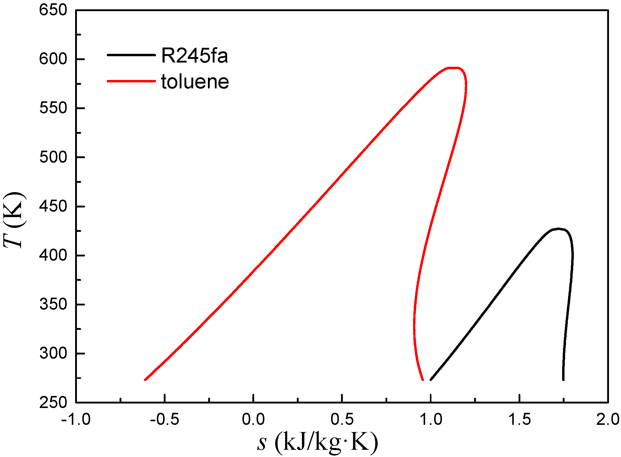
After the optimal blade installation angle and blade number are determined, other geometric parameters are also calculated, as listed in Table 3. Due to the low critical temperature and inlet temperature for working fluid R245fa, the specific enthalpy drop in the stator blade is low according to the T-s plots (Figure 13). Therefore, the chord length, cascade inlet diameter, and cascade outside diameter of the stator blade are larger, while the blade number is lower. These characteristics are advantage to improve the working fluid mass flow rate and the working capacity of the radial-inflow turbine. The critical temperature and inlet temperature for working fluid toluene are much higher than that for R245fa. The specific enthalpy drop in the stator blade is larger according to the T-s plots (Figure 13). Thus, less chord length, cascade inlet diameter, and cascade outside diameter of the stator blade and more blade number are preferred. These characteristics are beneficial to increase average outlet velocity and reduce the flow loss, which makes the working fluid entering the rotor more uniform.
4. Conclusions
This work investigates the effects of the blade installation angle and blade number on the performance of radial-inflow turbine stator. R245fa and toluene were selected as working fluids in the low and high temperature range, respectively. 2D stator blades model for the two working fluids were established. The CFD simulation method was used to analyse the performance of the stator blade. The distribution of static pressure along the stator blade, flow loss, average outlet temperature, and average outlet velocity were calculated with different blade installation angle and blade number. For low temperature working fluid R245fa, when the installation angle is 32° and blade number is 22, the distribution of static pressure has no obvious pressure fluctuation, and the flow loss is least. The stator blade obtained the optimal performance. For high temperature working fluid toluene, when the installation angle is 28° and blade number is 32, the average outlet temperature is the lowest, while the average outlet velocity is the largest. And the flow state is well and smooth, and no remarkable flow separation and shock wave presents. Due to the low critical temperature and inlet temperature, R245fa has lower specific enthalpy drop in the stator blade compared to toluene. Thus, the stator blade for R245fa has a larger chord length, cascade inlet diameter, and cascade outside diameter but a lower blade number.
Author Contributions
All authors contributed to this work. P.L. is the main author of this work. Z.H. guided the analysis and the writing of the paper. X.J. assisted with the modeling. Z.M. and X.H. provided suggestions with respect to article modification.
Funding
This research was funded by National Natural Science Foundation of China (51306059), and Fundamental Research Funds for the Central Universities (2017XS120).
Conflicts of Interest
The authors declare no conflict of interest.
Nomenclature
| b | Chord length of blade (mm) |
| C0 | Imaginary expansion speed (m/s) |
| c | Absolute velocity (m·s−1) |
| cp | Specific heat capacity (kJ/kg·K) |
| cp0 | Zero pressure specific heat capacity (kJ/kg·K) |
| Ratio of wheel diameter | |
| F1 | Synthetic function of turbulence model coefficients |
| F2 | Blending functions |
| k | Specific turbulence kinetic energy (m2/s2); thermal conductivity (W/(m·K)) |
| keff | Effective thermal conductivity (W/(m·K)) |
| kt | Turbulent thermal conductivity (W/(m·K)) |
| P | Pressure (kPa) |
| Pk | Generation term of turbulence |
| Prt | Turbulent Prandtl number |
| R | Ideal gas constant, J/mol K |
| t | Time (s) |
| Relative pitch | |
| S | Modulus of the mean rate-of-strain tensor |
| T | Temperature (K) |
| u | Peripheral velocity (m/s) |
| Turbulence velocity (m/s) | |
| Vm | Molar volume, m3/mol |
| w | Relative velocity (m/s) |
| x | X coordinate value (mm) |
| Velocity ratio | |
| yB | Y coordinate value of suction surface (mm) |
| yH | Y coordinate value of pressure surface (mm) |
| Subscripts | |
| 1 | Rotor inlet |
| 2 | Rotor outlet |
| c | Critical point |
| k | Turbulent kinetic energy |
| ω | Specific dissipation rate |
| Greek Letters | |
| α | Absolute velocity angle (°) |
| α1,α* | Coefficients in SST k-ω model |
| β | Relative velocity angle (°) |
| βk, βω, γ | Turbulence model coefficient |
| δij | Kronecker symnol |
| Isentropic entropy drop (kJ/kg) | |
| ηu | Peripheral efficiency |
| μ | Physical dynamic viscosity (Pa·s) |
| μeff | Effective dynamic viscosity (Pa·s) |
| μt | Turbulent dynamic viscosity (Pa·s) |
| ρ | Density (kg/m3) |
| Turbulence model constant | |
| τij | Stress tensor |
| Stator blade velocity coefficient | |
| Rotor blade velocity coefficient | |
| ω | Specific turbulence dissipation rate (m2/s2) |
| ω0 | Acentric factor |
| Ω | Degree of reaction |
References
- Zhang, C.; Fu, J.L.; Kang, J.; Fu, W.C. Performance optimization of low-temperature geothermal organic Rankine cycles using axial turbine isentropic efficiency correlation. J. Braz. Soc. Mech. Sci. Eng. 2018, 40, 61. [Google Scholar] [CrossRef]
- Zare, V. A comparative exergoeconomic analysis of different ORC configurations for binary geothermal power plants. Energy Convers. Manag. 2015, 105, 127–138. [Google Scholar] [CrossRef]
- Han, Z.H.; Li, P.; Han, X.; Mei, Z.K.; Wang, Z. Thermo-economic performance analysis of a regenerative superheating organic rankine cycle for waste heat recovery. Energies 2017, 10, 1593. [Google Scholar] [CrossRef]
- Feng, Y.; Zhang, Y.; Li, B.; Yang, J.; Shi, Y. Comparison between regenerative organic Rankine cycle (RORC) and basic organic Rankine cycle (BORC) based on thermoeconomic multi-objective optimization considering exergy efficiency and levelized energy cost (LEC). Energy Convers. Manag. 2015, 96, 58–71. [Google Scholar] [CrossRef]
- Song, J.; Gu, C.W.; Ren, X. Parametric design and off-design analysis of organic Rankine cycle (ORC) system. Energy Convers. Manag. 2016, 112, 157–165. [Google Scholar] [CrossRef]
- Wang, Y.Z.; Zhao, J.; Wang, Y.; An, Q.S. Multi-objective optimization and grey relational analysis on configurations of organic Rankine cycle. Appl. Therm. Eng. 2017, 114, 1355–1363. [Google Scholar] [CrossRef]
- Kim, D.Y.; Kim, Y.T. Preliminary design and performance analysis of a radial inflow turbine for ocean thermal energy conversion. Renew. Energy 2017, 106, 255–263. [Google Scholar] [CrossRef]
- Zheng, Y.; Hu, D.; Cao, Y.; Dai, Y. Preliminary design and off-design performance analysis of an organic rankine cycle radial-inflow turbine based on mathematic method and CFD method. Appl. Therm. Eng. 2017, 112, 25–37. [Google Scholar] [CrossRef]
- Dong, B.; Xu, G.; Luo, X.; Zhuang, L.; Quan, Y. Analysis of the supercritical organic Rankine cycle and the radial turbine design for high temperature applications. Appl. Therm. Eng. 2017, 123, 1523–1530. [Google Scholar] [CrossRef]
- Lio, L.D.; Manente, G.; Lazzaretto, A. A mean-line model to predict the design efficiency of radial inflow turbines in organic Rankine cycle (ORC) systems. Appl. Energy 2017, 205, 187–209. [Google Scholar] [CrossRef]
- Sauret, E.; Gu, Y. Three-dimensional off-design numerical analysis of an organic rankine cycle radial-inflow turbine. Appl. Energy 2014, 135, 202–211. [Google Scholar] [CrossRef]
- Rahbar, K.; Mahmoud, S.; Al-Dadah, R.K.; Moazami, N. Parametric analysis and optimization of a small-scale radial turbine for Organic Rankine Cycle. Energy 2015, 83, 696–711. [Google Scholar] [CrossRef]
- Colonna, P.; Rebay, S.; Harinck, J.; Guardone, A. Real-gas effects in ORC turbine flow simulations: Influence of thermodynamic models on flow fields and performance parameters. In Proceedings of the European Conference on Computational Fluid Dynamics, Egmond aan Zee, The Netherlands, 5–8 September 2006. [Google Scholar]
- Colonna, P.; Harinck, J.; Rebay, S.; Guardone, A. Real-gas effects in organic Rankine cycle turbine nozzles. J. Propul. Power 2008, 24, 282–294. [Google Scholar] [CrossRef]
- Fiaschi, D.; Manfrida, G.; Maraschiello, F. Design and performance prediction of radial ORC turboexpanders. Appl. Energy 2015, 138, 517–532. [Google Scholar] [CrossRef]
- Dong, B.; Xu, G.; Li, T.; Luo, X.; Quan, Y. Parametric analysis of organic Rankine cycle based on a radial turbine for low-grade waste heat recovery. Appl. Therm. Eng. 2017, 126, 470–479. [Google Scholar] [CrossRef]
- Li, Y.; Ren, X.D. Investigation of the organic Rankine cycle (ORC) system and the radial-inflow turbine design. Appl. Therm. Eng. 2016, 96, 547–554. [Google Scholar] [CrossRef]
- Li, Y.; Li, X.S.; Ren, X. Aerodynamic optimization of a high-expansion ratio organic radial-inflow turbine. J. Mech. Sci. Technol. 2016, 30, 5485–5490. [Google Scholar] [CrossRef]
- Song, Y.; Sun, X.; Huang, D.A. Preliminary design and performance analysis of a centrifugal turbine for Organic Rankine Cycle (ORC) applications. Energy 2017, 140, 1239–1251. [Google Scholar] [CrossRef]
- Bahadormanesh, N.; Rahat, S.; Yarali, M. Constrained multi-objective optimization of radial expanders in organic Rankine cycles by firefly algorithm. Energy Convers. Manag. 2017, 148, 1179–1193. [Google Scholar] [CrossRef]
- Han, Z.; Fan, W.; Zhao, R. Improved thermodynamic design of organic radial-inflow turbine and orc system thermal performance analysis. Energy Convers. Manag. 2017, 150, 259–268. [Google Scholar] [CrossRef]
- Zhai, L.; Xu, G.; Wen, J.; Quan, Y.; Fu, J.; Wu, H.; Li, T. An improved modeling for low-grade organic Rankine cycle coupled with optimization design of radial-inflow turbine. Energy Convers. Manag. 2017, 153, 60–70. [Google Scholar] [CrossRef]
- Pan, L.; Wang, H. Improved analysis of Organic Rankine Cycle based on radial flow turbine. Appl. Therm. Eng. 2013, 61, 606–615. [Google Scholar] [CrossRef] [Green Version]
- Song, J.; Gu, C.W.; Ren, X. Influence of the radial-inflow turbine efficiency prediction on the design and analysis of the Organic Rankine Cycle (ORC) system. Energy Convers. Manag. 2016, 123, 308–316. [Google Scholar] [CrossRef]
- Lee, Y.; LU, G. Radial Inflow Turbine and Centrifugal Compressor; China Machine Press: Beijing, China, 1984. [Google Scholar]
- Dong, B.; Xu, G.; Li, T.; Quan, Y.; Zhai, L.; Wen, J. Numerical prediction of velocity coefficient for a radial-inflow turbine stator using R123 as working fluid. Appl. Therm. Eng. 2018, 130, 1256–1265. [Google Scholar] [CrossRef]
- Harinck, J.; Turunen-Saaresti, T.; Colonna, P.; Rebay, S.; Van, B. Computational study of a high-expansion ratio radial organic rankine cycle turbine stator. J. Eng. Gas Turbines Power 2010, 132, 054501. [Google Scholar] [CrossRef]
- Pasquale, D.; Ghidoni, A.; Rebay, S. Shape optimization of an organic rankine cycle radial turbine nozzle. J. Eng. Gas Turbines Power 2013, 135, 042308. [Google Scholar] [CrossRef]
- Uusitalo, A.; Turunen-Saaresti, T.; Guardone, A.; Grönman, A. Design and flow analysis of a supersonic small scale ORC turbine stator with high molecular complexity working fluid. In Proceedings of the ASME Turbo Expo 2014, Turbine Technical Conference and Exposition, Düsseldorf, Germany, 16–20 June 2014. [Google Scholar]
- White, M.; Read, M.; Sayma, A. Using a cubic equation of state to identify optimal working fluids for an ORC operating with two-phase expansion using a twin-screw expander. In Proceedings of the 17th International Refrigeration and Air Conditioning Conference, Purdue, IN, USA, 9–12 July 2018. [Google Scholar]
Figure 1.
Velocity triangles of radial-inflow turbine.

Figure 2.
relationship curves for TC-4P blade profile.

Figure 3.
Two-dimensional model of stator blade.

Figure 4.
The unstructured mesh around the stator blade.
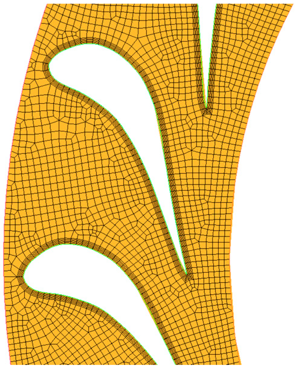
Figure 5.
Validation of mesh independence.
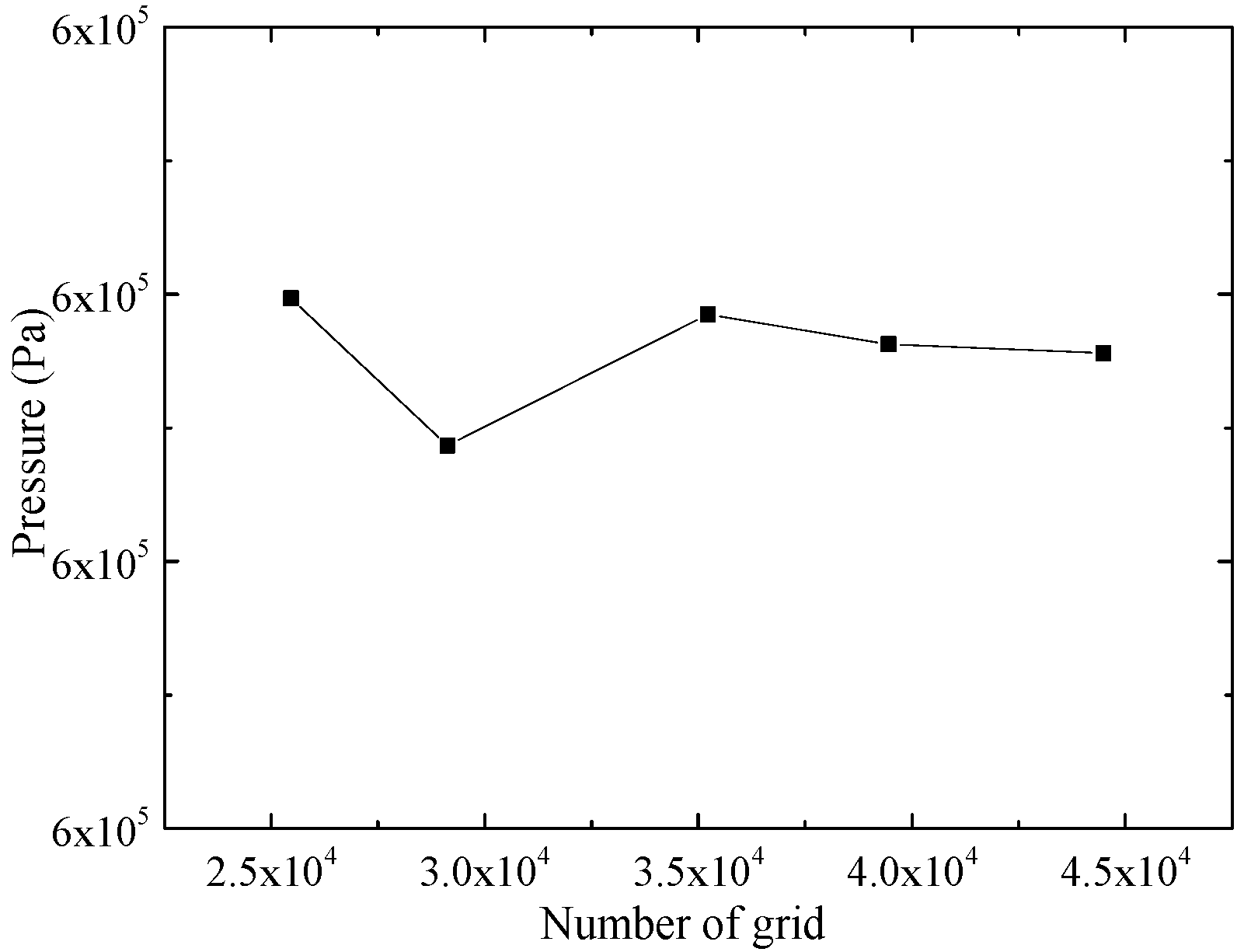
Figure 6.
Static pressure distribution around the stator blade surface with blade number 22.
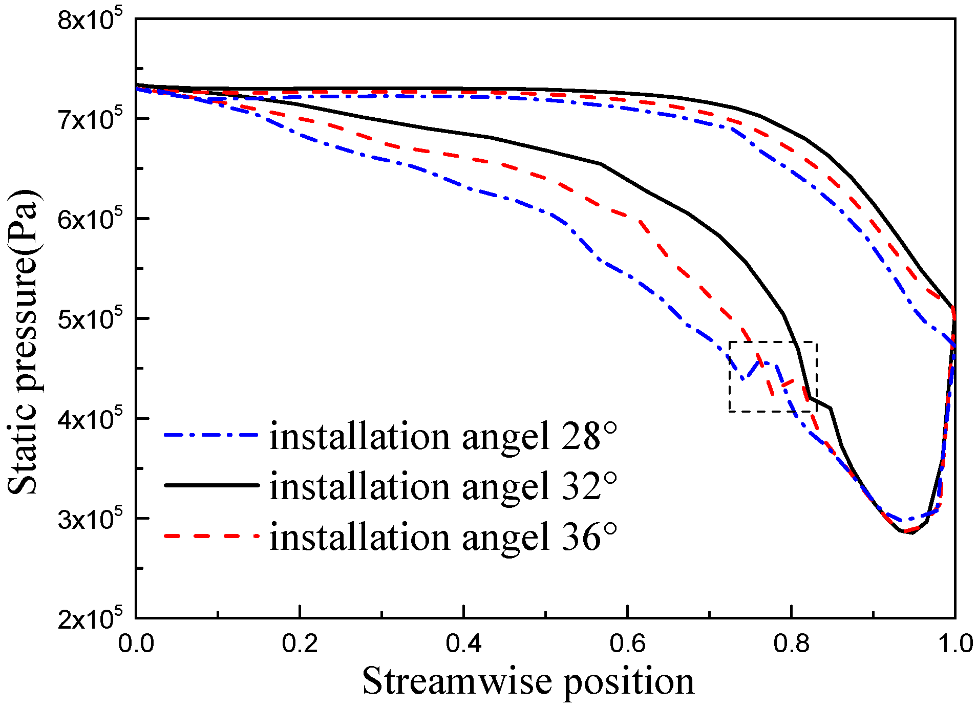
Figure 7.
Flow loss at different blade installation angle with blade number 22.
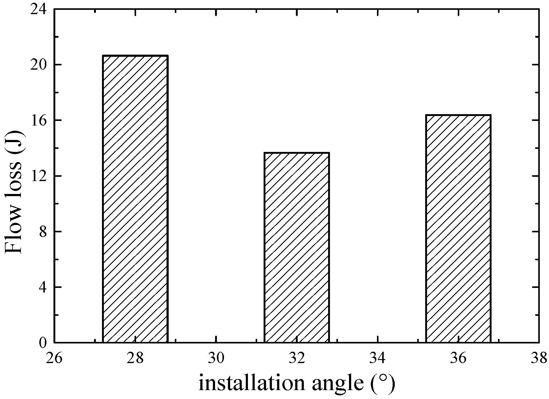
Figure 8.
Static pressure distribution along the nozzle blade surface with installation angle 32°.

Figure 9.
Flow loss at different blade number with installation angle 32°.
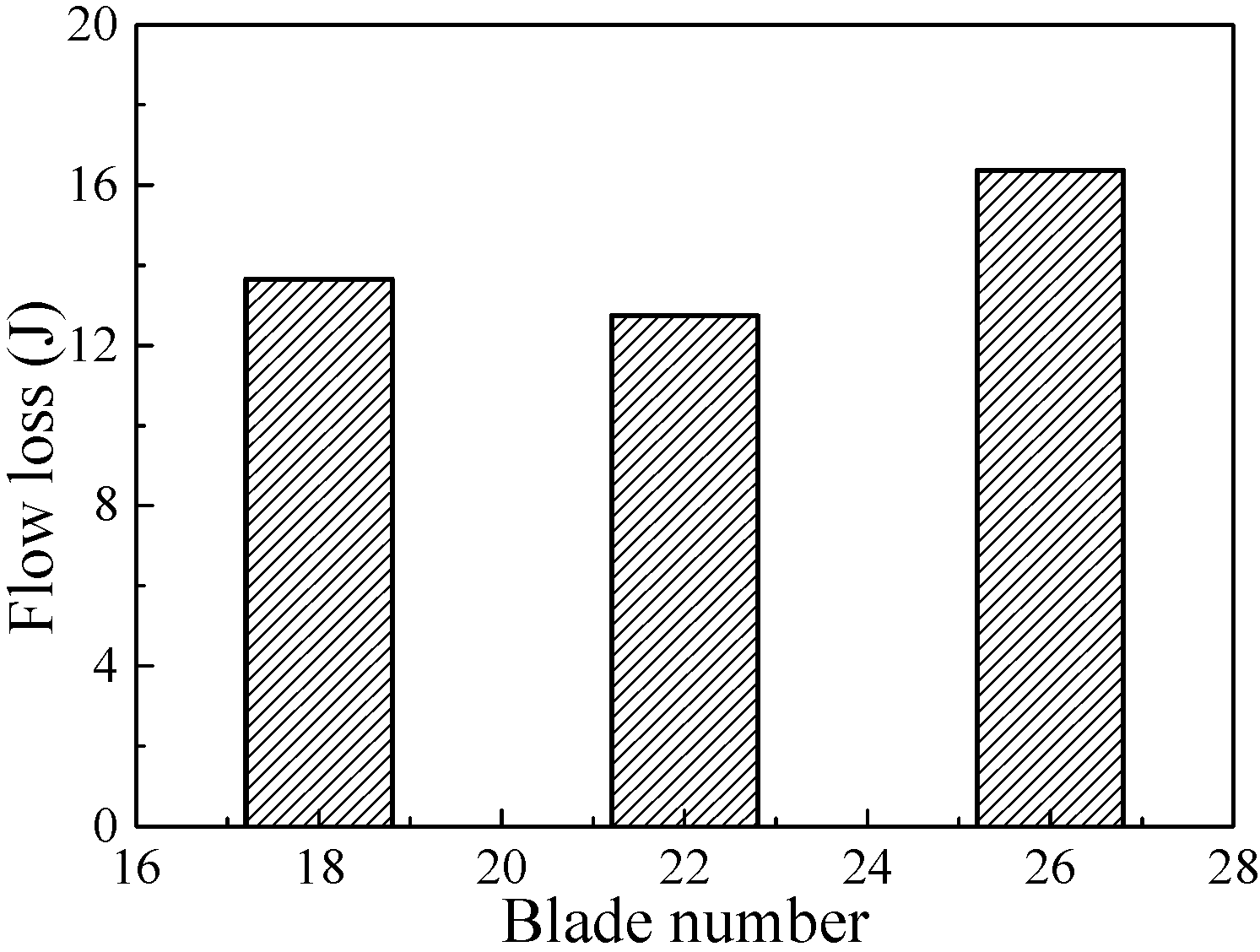
Figure 10.
Average outlet temperature and average outlet velocity for stator blade with blade number 32.
Figure 10.
Average outlet temperature and average outlet velocity for stator blade with blade number 32.
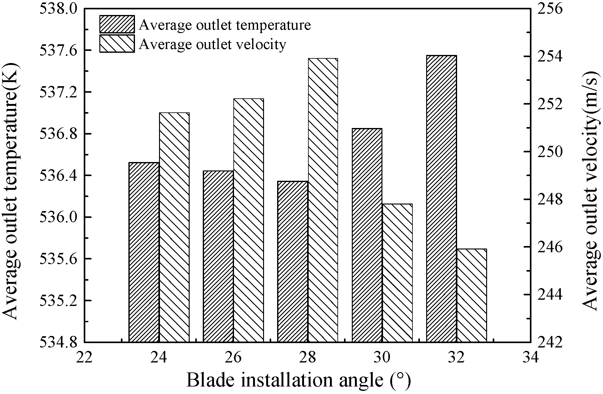
Figure 11.
Average outlet temperature and velocity of stator with an installation angle of 28°.
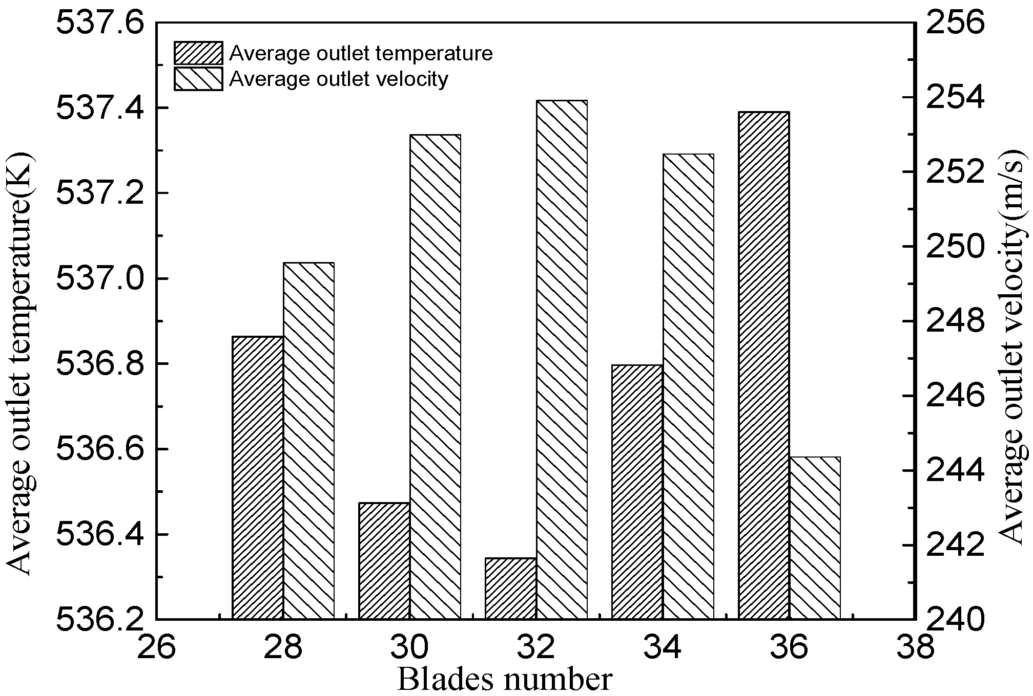
Figure 12.
Streamlines in the stator blade with an installation angle of 28° and blade number 32.

Figure 13.
The T-s plots for working fluids.

Table 1.
Relative coordinates for the TC-4P blade profile.
| x/b (%) | yB/b (%) | yH/b (%) | x/b (%) | yB/b (%) | yH/b (%) |
|---|---|---|---|---|---|
| 0 | 0.453 | 0.453 | 55 | 24.40 | 11.70 |
| 0.25 | 1.57 | 0.280 | 60 | 26.35 | 12.96 |
| 5.0 | 2.545 | 0.815 | 65 | 27.7 | 11.8 |
| 7.5 | 3.445 | 1.45 | 70 | 28.6 | 10.9 |
| 10.0 | 4.46 | 2.10 | 75 | 29.0 | 2.24 |
| 12.5 | 5.45 | 2.72 | 80 | 28.4 | 7.15 |
| 15.0 | 6.52 | 3.39 | 82.5 | 27.9 | 5.9 |
| 17.5 | 7.59 | 4.005 | 85 | 27.2 | 4.44 |
| 20 | 8.66 | 4.65 | 87.5 | 26.3 | 2.72 |
| 25 | 10.84 | 5.94 | 90 | 25.0 | 0.127 |
| 30 | 13.06 | 7.20 | 92.5 | 23.4 | 0.362 |
| 35 | 15.35 | 8.47 | 95 | 21.2 | 0 |
| 40 | 17.69 | 9.46 | 97.5 | 17.4 | 0.905 |
| 45 | 4519.90 | 10.50 | 100 | 7.43 | 7.43 |
| 50 | 22.4 | 11.23 |
Table 2.
Comparison of 1D thermal design and numerical 2D turbulent simulation.
| Variables | 1D Thermal Design | CFD Numerical Results | Deviation (%) |
|---|---|---|---|
| Inlet temperature (K) | 353.15 | 352.53 | −0.18 |
| Outlet temperature (K) | 328.66 | 328.54 | −0.037 |
| Inlet pressure (MPa) | 0.7355 | 0.7258 | −1.32 |
| Outlet pressure (MPa) | 0.3210 | 0.3209 | −0.031 |
| Velocity coefficient | 0.95 | 0.93 | −2.1 |
Table 3.
Geometric parameters of stator blades.
| Working Fluids | R245fa | Toluene |
|---|---|---|
| Chord length (mm) | 44.05 | 30.55 |
| Installation angle (°) | 32° | 28° |
| Blade number | 22 | 32 |
| Relative pitch | 0.67 | 0.65 |
| Cascade inlet diameter (mm) | 206 | 194 |
| Cascade outside diameter (mm) | 297 | 210 |
© 2018 by the authors. Licensee MDPI, Basel, Switzerland. This article is an open access article distributed under the terms and conditions of the Creative Commons Attribution (CC BY) license (http://creativecommons.org/licenses/by/4.0/).
Share and Cite
MDPI and ACS Style
Li, P.; Han, Z.; Jia, X.; Mei, Z.; Han, X. Analysis of the Effects of Blade Installation Angle and Blade Number on Radial-Inflow Turbine Stator Flow Performance. Energies 2018, 11, 2258. https://doi.org/10.3390/en11092258
AMA Style
Li P, Han Z, Jia X, Mei Z, Han X. Analysis of the Effects of Blade Installation Angle and Blade Number on Radial-Inflow Turbine Stator Flow Performance. Energies. 2018; 11(9):2258. https://doi.org/10.3390/en11092258
Chicago/Turabian StyleLi, Peng, Zhonghe Han, Xiaoqiang Jia, Zhongkai Mei, and Xu Han. 2018. "Analysis of the Effects of Blade Installation Angle and Blade Number on Radial-Inflow Turbine Stator Flow Performance" Energies 11, no. 9: 2258. https://doi.org/10.3390/en11092258
Note that from the first issue of 2016, this journal uses article numbers instead of page numbers. See further details here.