Article

Visualization Investigation of the Influence of Chamber Profile and Injection Parameters on Fuel Spray Spreading in a Double-Layer Diverging Combustion Chamber for a DI Diesel Engine

1
School of Energy and Power Engineering, Dalian University of Technology, Dalian 116024, China
2
Graduate School of Engineering, Chiba University, Chiba 2638522, Japan
3
Institute for Energy Research, Jiangsu University, Zhenjiang 212013, China
*
Author to whom correspondence should be addressed.
Energies 2018, 11(9), 2343; https://doi.org/10.3390/en11092343
Submission received: 7 August 2018 / Revised: 26 August 2018 / Accepted: 3 September 2018 / Published: 5 September 2018
(This article belongs to the Special Issue Internal Combustion Engines 2018)

Abstract

:
The double-layer diverging combustion chamber (DLDC chamber) aims to improve the fuel–air mixing formation and promote in-cylinder air utilization by changing fuel spray spreading characteristics. In order to investigate how the DLDC chamber profile and injection parameters affect the fuel spray spreading, visualization of fuel injection and impingement tests were carried out on two different DLDC chambers with different fuel injection parameters. The visualization test results showed that double-layer fuel spray spreading was obtained in the two DLDC chambers and the peripheral top clearance of each chamber was utilized efficiently. The DLDC chamber with a 50% upper layer volume provided a larger fuel spray distribution region after the start of injection. The DLDC chamber with a 70% upper layer volume obtained a larger fuel spray distribution region with better top clearance utilization at the later stage of injection. The injection parameters mentioned in this research showed significant effects on the fuel spray spreading in the DLDC chamber. Increasing the injection pressure provided a larger fuel spray distribution area at the beginning of injection. Decreasing the nozzle hole diameter had a positive influence on obtaining a larger fuel spray distribution. Advancing the injection timing enabled the enlarging of the fuel distribution region.

1. Introduction

Since the fossil energy shortages and air pollution have become increasingly serious in recent years, a series of brake-specific fuel consumption (BSFC) standards and strict emission control regulations have been released for diesel engines [1,2,3]. Decreasing diesel engine BSFC and harmful emissions is a great challenge.
Su et al. [4] investigated how chamber wall and injection parameters affected spray in a constant volume bomb by the shadowgraph method. Fuel impingement is the key point in balancing the fuel–air mixing and rich fuel spray distribution. Katsura et al. [5] investigated the effects of ambient conditions and proposed an experimental equation for the height and radius of the impinging spray. This research points out that the fuel jet is divided into the main jet region and wall jet region after the fuel is impinged to a flat wall. Montajir et al. [6,7] researched the effects of diesel chamber geometry and the in-cylinder reverse squish on the fuel spray behavior in an optical engine with a square chamber by the shadowgraph method. The results show that a larger injection angle provides longer floor jets with less fuel outside the chamber, and the re-entrant chamber with a round lip and bottom corner makes the fuel distribution better. Many other investigations [8,9,10,11,12,13,14,15], such as into injection strategies, nozzle structures, fuel properties, chamber structures and in-cylinder flow fields, were carried out. In brief, these investigations focused on fuel spray, air motion, and chamber profile and their interactions. One of the results is that optimizing spray and combustion processes by designing combustion chambers and matching chamber–spray–charge motion is one of the major measures to reduce BSFC and harmful emissions.
Hence, the combustion chamber geometry obviously affects the fuel spray spreading and fuel–air mixing processes. Furthermore, changing the chamber profile does not cause additional manufacturing costs. Therefore, optimizing the combustion chamber profile is a high-efficiency and low-cost method to improve diesel engine performance. In the past decades, many new kinds of diesel engine chambers have been proposed. Some of them are developed based on the re-entrant chamber; these chambers employ round lips and squish pips to enlarge the fuel spray distribution and provide high turbulence [16,17]. Doosan [18], Toyota [19], Ricardo [20] and Ford [21] changed the re-entrant chamber’s round lip into a tapered lip or a stepped lip and set a declining surface around the re-entrant entrance. Benz [22] and Mazda [23] moved the re-entrant chamber round lips downward and obtained stepped bowl chambers. These chambers present good in-cylinder air utilization with small peripheral top clearance volumes. Meanwhile, the fuel adhesion on the piston top surface is restrained by changing the reverse squish. Therefore, BSFC and harmful emissions, especially soot and CO, are decreased [24,25]. Some other chambers are developed based on the ω chamber, such as the double swirl combustion system (DSCS) chamber [26] and the bump chamber [27]. These chambers are focused on optimizing the fuel–wall impinging and minimizing fuel piling on the cavity wall to accelerate the fuel–air mixing rate.
The extant studies indicate the necessity of the optimization of the chamber profile and fuel–wall impinging. Therefore, the double-layer diverging combustion chamber (DLDC chamber) [28] has been designed to utilize the entirety of the in-cylinder air and enlarge the fuel spray distribution with less fuel piling and a high fuel–air mixing rate [29]. Figure 1 is the basic schematic diagram of the DLDC chamber. The narrow ring located in the middle of the cavity side wall is named as the impinging circular surface, and the other ring located at the lower edge of the impinging circular surface is named as the fuel stripping surface. These two rings form the impinging platform, which divides the chamber cavity into the upper layer and the lower layer. The fuel spray target is the impinging platform. Figure 2 shows the profile comparison of the DLDC chamber, ω chamber and re-entrant chamber. Among these three chambers, the DLDC chamber has the largest opening diameter on the piston top surface; it provides the smallest peripheral top clearance volume and the highest in-cylinder air utilization index (κ-factor) [30]. The DLDC chamber provides the smallest cavity throat diameter; this provides the most rapid fuel impingement on the chamber cavity wall, and the fuel adhesion on the cavity wall can be largely restrained according to references [29,31]. In this paper, the major objective is to find out the influence of a chamber profile with different injection parameters on the fuel spray spreading process in the DLDC chamber by a visualization method.

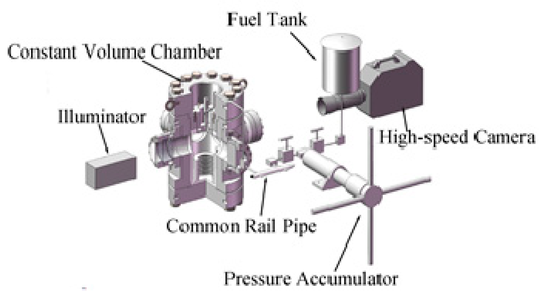
2. Experimental Setup and Method

Two different DLDC chambers were employed in this visualization test. These chambers were used in a single-cylinder diesel engine whose cylinder bore was 135 mm, displacement was 2.15 L, compression ratio was 16.5 and rated power was 14.7 kW. Two solenoid-valve injectors with multi-hole nozzles were applied in this diesel engine; the nozzles types were 8 × 150° × Φ0.16 mm and 7 × 150° × Φ0.18 mm (nozzle hole number × fuel spray cone angle × nozzle hole diameter). Figure 3 shows the profiles of these two DLDC chambers. In this figure, the shadow part is called the upper layer volume, and the ratio of the upper layer volume to the piston cavity volume is defined as the P factor. These two chambers have the same volumes of 105 mL. The type I DLDC chamber has a larger cavity throat diameter of 77 mm, and its P factor is 50%, while the type II DLDC chamber has a smaller throat diameter of 71 mm, and its P factor is 70%.
The shadowgraph method [32] was applied in this research, which is widely used as a tool for flow visualization testing in heat transfer and fluid mechanics [33,34]. The spray visualization measurement apparatuses consist of a constant volume chamber (CVC), a fuel injection system, a high-speed photographing system and a synchronous control system. Figure 4 shows the schematic diagram of these apparatuses. Table 1 lists these visualization measurement apparatus specifications. There are four observing windows arranged on the CVC side wall. The fuel injection system consists of a high-pressure common-rail pipe, a solenoid-valve fuel injector and a pressure accumulator. The maximum injection pressure of the fuel injection system is 160 MPa. The high-speed photographing system is composed of a high-speed camera, a lens and an illuminator. The synchronous control system comprises CompactRIO data measurement apparatuses including the control modules. The control logic and running mode of the synchronous control system shown in Figure 5 is established with LabVIEW. A detailed description of the experimental setup can be found in reference [29].
During the visualization test, the fuel spray was injected to the impinging block, which is a two-dimensional model employing the chamber profile characteristics and illuminated by the parallel light of the illuminator from one side of the impinging block. Two solenoid-valve injectors equipped with single-hole nozzles were employed in this research. The nozzle hole diameters are Φ0.16 mm and Φ0.18 mm respectively, which represented a hole in an eight-hole nozzle and in a seven-hole nozzle applied in the real diesel engine, respectively. The angular relationship between the impinging block and the nozzle hole and the nozzle hole position were set as equal to the real engine multi-hole nozzle cone angle. Figure 6 shows the schematic diagram of the relative positions between the spray axis and the piston position at different injection timings. Figure 7 shows the spatial relationship of the solenoid-valve injector, the illuminator and the impinging block, which is a two-dimensional model employing the chamber profile characteristics. Figure 8 shows the installation of the impinging block and the solenoid-valve injector in the CVC.
The medium load and full load frequently used in the real engine were selected for this visualization test. These two loads were represented by injection pulse and injection pressure. In order to distinguish the fuel spray spreading with different injection timing obviously and confirm the influence of injection timing on the fuel spray spreading process, a 15 °CA BTDC (crank angle before top dead center) and 5 °CA BTDC were selected, which are the two end injection timings in the real diesel engine at the medium load and full load. Table 2 lists the piston displacements at different crank angles around the top dead center; the displacement variation is very small. Therefore, the injection timing was represented by the piston position in this visualization test. The detailed parameters of fuel, nozzles, injection timings, injection pressures and injection pulses are listed in Table 3. The operation modes for these visualization tests are listed in Table 4. All the data listed in Table 3 and Table 4 are set according to the real diesel engine bench test results. The fuel mass of the Φ0.16 mm single-hole nozzle was 1/8th that of the eight-hole nozzle, and the fuel mass of the Φ0.18 mm single-hole nozzle was 1/7th that of the seven-hole nozzle in the real diesel engine.
The ambient gas in the CVC was nitrogen, the ambient temperature was set at 303 K, and the ambient pressures were set at 2.7 MPa and 3.4 MPa, which were approximate to the in-cylinder pressures of the real diesel engine at 15 °CA BTDC and 5 °CA BTDC, respectively. The frame rate of the high-speed camera was set at 20,000 fps, the aperture was set at 10.3 and the exposure time was set at 1/20,409 s. The photo resolution was 872 × 752. The brightness and contrast of the photos were adjusted to distinguish the details of the fuel spray distribution. MATLAB was applied to translate the photos into black–white binary images to calculate the fuel spray distribution area. In order to find out the influence of the chamber profile with different injection parameters on the fuel spray distribution exactly, the fuel spray distribution area and the fuel spray distribution ratio excluded the free fuel spray—the fuel spray between the nozzle and the impinging block. The fuel spray distribution ratio was the ratio of the fuel spray distribution area to the upper layer and top clearance cross-sectional area or the lower layer cross-sectional area.

3. Results and Discussion

3.1. Influence of Injection Pressure and Chamber Profile

Figure 9 shows the comparison of the fuel spray distributions between the two DLDC chambers on Mode A. The impinging platform split the fuel spray into the two different layers. The fuel spray in the lower layer of the type I DLDC chamber was stripped away from the cavity wall by the fuel stripping surface at 0.8 ms ASOI (after the start of injection) with 110 MPa injection pressure, and the fuel spray in the upper layer of the type II DLDC chamber was stripped away from the upper layer’s bottom by the impinging circular surface at 0.8 ms ASOI with the two injection pressures. These phenomena suggest that both the impinging circular surface and the fuel stripping surface can strip the fuel spray away from the cavity wall, and this is good for strengthening the air entrainment. The fuel spray spreading in the top region of the type II DLDC chamber was more obvious than in the type I DLDC chamber at 2.0 ms ASOI with the two injection pressures, because its larger opening diameter on the piston top surface led to a smaller peripheral top clearance volume. This indicates that a larger upper layer volume with a larger opening diameter on the piston top surface is better at utilizing the air in the chamber top clearance.
Figure 10 shows the fuel spray distribution comparison of the two chambers at 1.4 ms ASOI with different brightness and contrast in Mode A. The rich fuel spray distribution regions in the peripheral top clearance and around the cavity wall of the type I DLDC chamber became more obvious with 150 MPa injection pressure. The rich fuel spray distribution region around the upper layer bottom of the type II DLDC chamber was more obvious with 150 MPa injection pressure. These phenomena suggest that a higher injection pressure increases the peripheral top clearance utilization and provides a larger fuel spray distribution in a short period.
Figure 11 shows the comparison of the fuel spray distribution areas between the two DLDC chambers in Mode A. Increasing the injection pressure enlarged the fuel spray distribution area significantly after the start of injection. However, the fuel spray distribution areas in the two chambers with 110 MPa injection pressure became larger at the later stage of injection. Furthermore, the fuel spray distribution area of the type I DLDC chamber with 150 MPa injection pressure was decreased obviously after 1.6 ms ASOI. This was because the higher injection pressure shortened the injection pulse and injected more fuel at the beginning of injection, while lower injection pressure provided a longer injection period. The type I DLDC chamber provided a larger fuel spray distribution area than the type II DLDC chamber with the same injection pressure after the start of injection, while the situations were reversed at the later stage of injection. These phenomena indicate that the DLDC chamber with a 50% upper layer volume can provide a larger fuel spray distribution area after the start of injection and its chamber profile limits the fuel spray distribution at the later stage of injection, while the DLDC chamber with a 70% upper layer volume provides a larger fuel spray distribution area with a higher in-cylinder air utilization, which increases the time of the fuel spray.
Figure 12 shows the fuel spray distribution ratios of different layers at different times in Mode A. The upper layer and top clearance distribution ratio of the type I DLDC chamber was only higher than its lower layer distribution ratio at 2.0 ms ASOI. The upper layer and top clearance distribution ratio of the type II DLDC chamber was the highest with the same injection pressure and the same time. These phenomena suggest that the DLDC chamber with a larger upper layer volume utilizes the top clearance better.

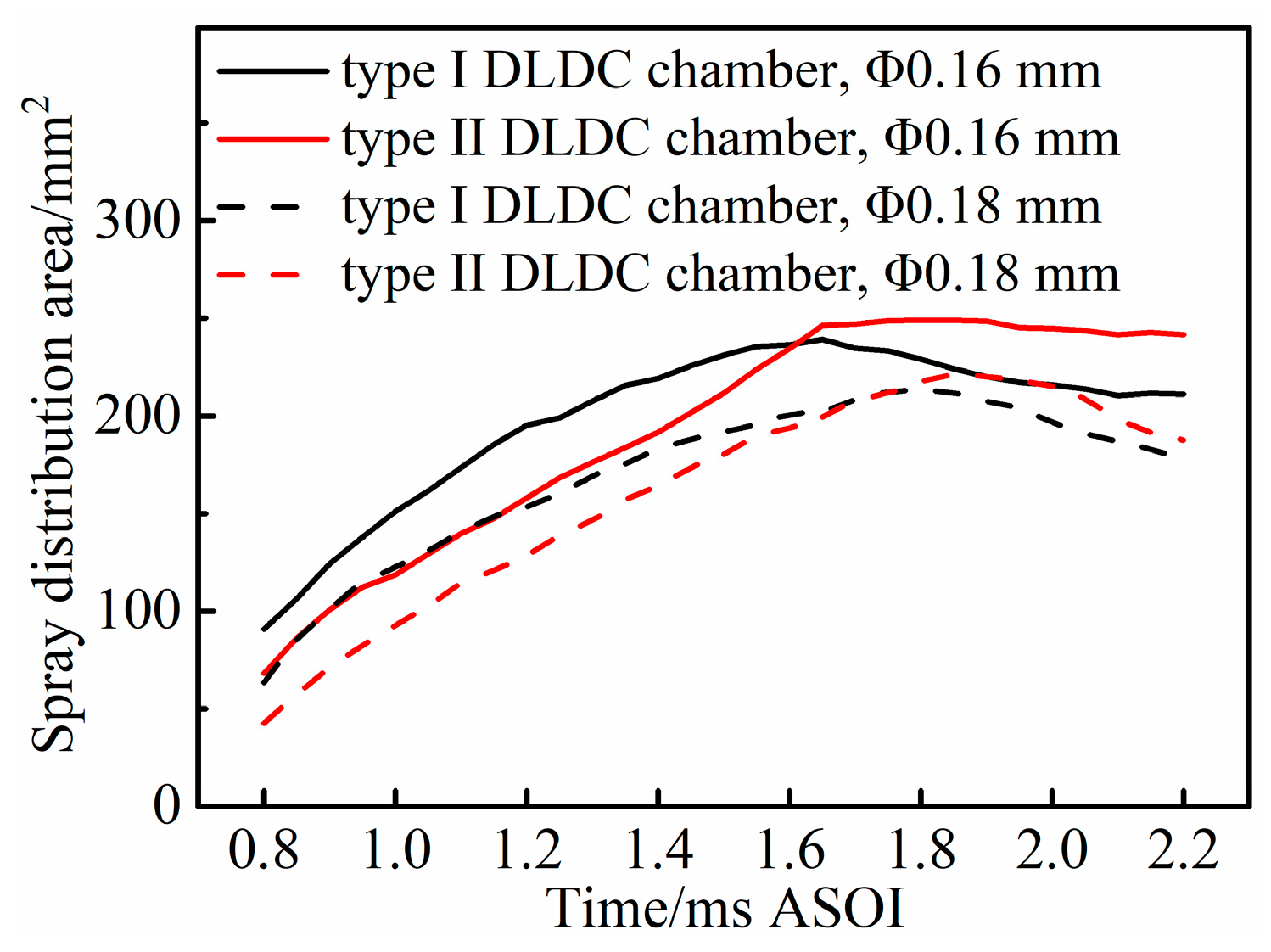
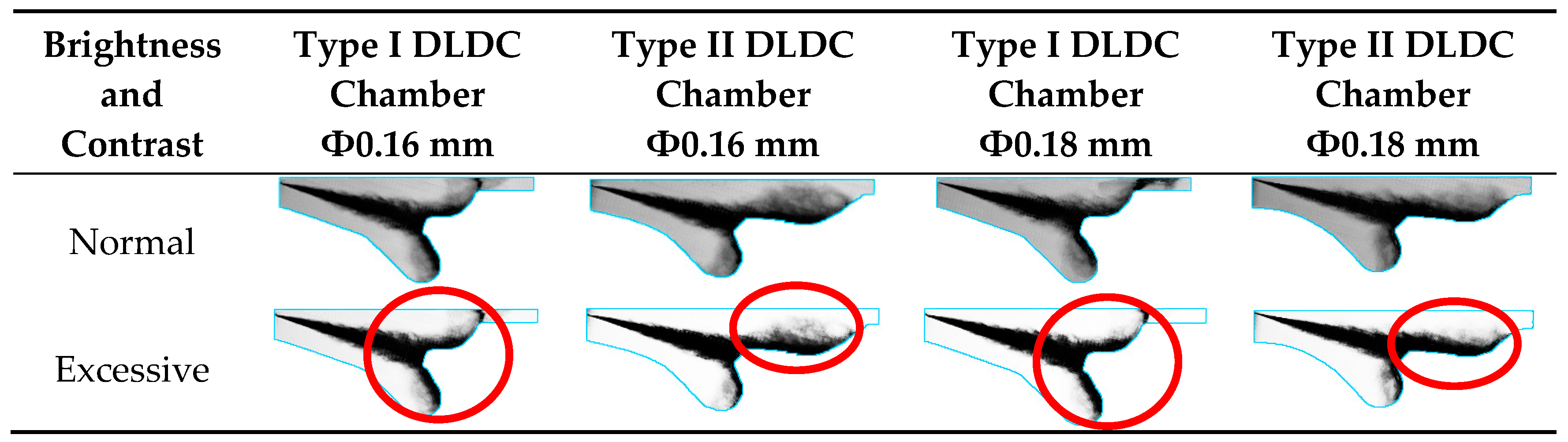
3.2. Influence of Nozzle Hole Diameter and Chamber Profile

Figure 13 shows the comparison of fuel spray distributions between the two DLDC chambers in Mode B. The type I DLDC chamber with the Ф0.18 mm nozzle provided a slightly longer fuel spray spreading distance in its upper layer than that achieved with the Ф0.16 mm nozzle at 0.8 ms ASOI, while the fuel spray was more obvious in its upper layer with the Ф0.16 mm nozzle at 1.4 ms ASOI and 2.0 ms ASOI. The fuel spray was restrained slightly in the type I DLDC chamber lower layer with the Ф0.18 mm nozzle. There was no obvious difference between the fuel spray spreading distances in the upper layer of the type II DLDC chamber with different nozzles: the fuel spray spreading in its lower layer was restrained at 1.4 ms and 2.0 ms ASOI when the Ф0.18 mm nozzle was employed. These phenomena suggest that the DLDC chamber with a 70% upper layer volume is better for encouraging the fuel spray spreading in its upper layer with different nozzles, and smaller hole diameter nozzles provide a better fuel spray spreading for the DLDC chamber.
Figure 14 shows the fuel spray comparison of the two chambers at 1.4 ms ASOI with different brightness and contrast in Mode B. The rich fuel spray distribution regions around the upper layer bottoms of the two DLDC chambers with the Ф0.18 mm nozzle were larger than those with the Ф0.16 mm nozzle, and there was no significant difference in the rich fuel spray distribution region of each DLDC chamber’s lower layer with different nozzles, while the fuel spray distribution regions of the two chambers with the Ф0.16 mm nozzle were larger than those with the Ф0.18 mm nozzle, especially in the upper layers. These phenomena suggest that smaller hole diameter nozzles provide a more homogeneous fuel spray distribution for the DLDC chamber.
Figure 15 shows the comparison of fuel spray distribution areas between the two DLDC chambers in Mode B. The fuel spray distribution areas of these cases increased to their maximal values and then decreased. The Ф0.16 mm nozzle provided a larger fuel spray distribution area than the Ф0.18 mm nozzle in each DLDC chamber. This indicates that smaller hole diameter nozzles are better for the fuel spray to obtain a larger distribution region in the DLDC chamber. With the same nozzle, the type I DLDC chamber provided a larger fuel spray distribution area than the type II DLDC chamber after the start of injection, while the type II DLDC chamber provided a larger fuel spray distribution area at the later stage of injection. These phenomena indicate that the DLDC chamber with a 50% upper layer volume can provide a larger fuel spray distribution region at the beginning of the injection, while the DLDC chamber with a 70% upper layer volume provides a larger fuel spray distribution area at the later stage of injection.
Figure 16 shows the fuel spray distribution ratios of different layers at different times in Mode B. The lower layer distribution ratio of the type I DLDC chamber was higher than that of the type II DLDC chamber, and the upper layer and top clearance distribution ratio of the type II DLDC chamber were higher than those of the type I DLDC chamber. These phenomena suggest that a larger space is better for fuel spray distribution. The fuel spray distribution ratios of the two chambers were decreased when the Ф0.18 mm nozzle was employed. This indicates that smaller hole diameter nozzles are more helpful for the DLDC chamber to improve the in-cylinder air utilization.

3.3. Influence of Nozzle Hole Diameter and Injection Timing (Piston Position)

Figure 17 shows the comparison of fuel spray distributions between the two DLDC chambers in Mode C. The fuel spray in the type I DLDC chamber peripheral top clearance was closer to the cylinder wall with the Ф0.18 mm nozzle than that with the Ф0.16 mm nozzle at 1.4 ms and 2.0 ms ASOI. The fuel spray distribution in the type II DLDC chamber upper layer with the Ф0.16 mm nozzle was more obvious than that with the Ф0.18 mm nozzle at 1.4 ms and 2.0 ms ASOI. These phenomena suggest that a larger hole diameter with earlier injection timing makes the fuel spray flow towards the chamber wall more quickly; this is good for the DLDC chamber with a 50% upper layer volume to utilize the peripheral top clearance well. However, this is not good for the larger upper layer of the DLDC chamber with a 70% upper layer volume. When the nozzle was adjusted to the Ф0.18 mm nozzle, the fuel spray spreading in each chamber lower layer was not as apparent as with the Ф0.16 mm nozzle at 0.8 ms and 2.0 ms ASOI. This indicates that a smaller hole diameter nozzle is better for the fuel spray distribution in the lower layer of the DLDC chamber.
Figure 18 shows the fuel spray distribution ratios of different layers at 1.4 ms ASOI under different brightness and contrast in Mode C. There was no significant difference in the rich fuel spray distribution regions around the cavity wall of the type I DLDC chamber with different nozzles, while the rich fuel spray distribution region in the type II DLDC chamber upper layer was concentrated with the Ф0.18 mm nozzle. These phenomena suggest that the nozzle hole diameter has a more obvious influence on the fuel spray distribution in the DLDC chamber with a 70% upper layer volume.
Figure 19 shows the comparison of fuel spray distribution areas between the two DLDC chambers in Mode C. The type II DLDC chamber with a Ф0.16 mm nozzle provided the largest fuel spray distribution area, and with the Ф0.18 mm nozzle it provided the smallest fuel spray distribution area before 2.0 ms ASOI, which meant that smaller hole diameter nozzle was better for the type II DLDC chamber to obtain a larger fuel spray distribution region. The fuel spray distribution differences of different nozzles in the type I DLDC chamber were much smaller than those in the type II DLDC chamber. These phenomena indicate that the nozzle hole diameter has a more obvious influence on the fuel spray distribution in the DLDC chamber with a 70% upper layer volume.
Figure 20 shows the fuel spray distribution ratios of different layers at different times in Mode C. The upper layer and top clearance distribution ratio of the type I DLDC chamber was smaller than its lower layer, except for 2.0 ms ASOI with the Ф0.16 mm nozzle, which meant that the top clearance utilization of the type I DLDC chamber should be promoted. The upper layer and top clearance distribution ratio of the type II DLDC chamber with a Ф0.16 mm nozzle was higher than it was with the Ф0.18 mm nozzle. The type II DLDC chamber lower layer ratio was increased with a Ф0.16 mm nozzle, while this ratio was decreased with a Ф0.18 mm nozzle from 1.4 ms ASOI to 2.0 ms ASOI. These phenomena suggest that a smaller hole diameter nozzle is better for the DLDC chamber with a 70% upper layer volume for enlarging the fuel spray distribution region.
Figure 21 shows the comparison of fuel spray distribution areas between the two DLDC chambers with different injection timings and a Ф0.18 mm nozzle. The type I DLDC chamber obtained a larger fuel spray distribution area with 15 °CA BTDC than it did with 5 °CA BTDC after 1.1 ms ASOI, and the type II DLDC chamber with 15 °CA BTDC obtained a larger fuel spray distribution area than it did with 5 °CA BTDC during the whole process. These results might be caused by the interaction of the increased fuel mass and the larger top clearance volume. These meant that advancing the injection timing changed the fuel spray target by decreasing the impinging platform position and increasing the top clearance volume, and more fuel flowed into the upper layer and the larger top clearance volume. The larger upper layer volume of the type II DLDC chamber showed a greater advantage for enlarging the fuel spray distribution under these conditions. These phenomena suggest that advancing injection timing is good for enlarging fuel spray distribution in the DLDC chamber.
Figure 22 shows the fuel spray distribution ratios of different layers with different injection timings and a Ф0.18 mm nozzle. The lower layer distribution ratios of the two chambers with 15 °CA BTDC were higher than those with 5 °CA BTDC. These might be caused by the interaction of the injection timing and the injection mass. The upper layer and top clearance distribution ratios of the two chambers with 15 °CA BTDC were smaller than those with 5 °CA BTDC. These meant that the fuel spray target made more fuel flow into the upper layer and the top clearance, but some space of the top clearance and the upper layer were still not filled by the fuel spray. These phenomena suggest that advancing injection timing can improve the fuel spray distribution; however, the larger top clearance is not utilized very well.

4. Conclusions

In this paper, the fuel spray impingement and spreading characteristics of two DLDC chambers were tested by a visualization method in the CVC. According to the visualization test results, the following conclusions are made:
(1)
Both DLDC chambers can split the fuel spray into two layers under different injection conditions by their impinging platforms and utilize the peripheral top clearances well. The impinging circular surface and the fuel stripping surface can strip the fuel spray away from the piston cavity wall;
(2)
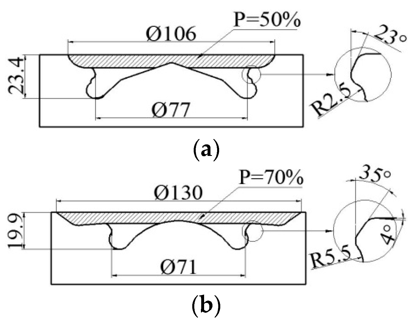
The DLDC chamber with a 50% upper layer volume can obtain a larger fuel spray distribution region at the beginning of injection. The DLDC chamber with a 70% upper layer volume can obtain a larger fuel spray distribution region with better top clearance utilization, but it needs a longer distribution time;
(3)
Injection parameters show significant effects on the fuel spray spreading in the two DLDC chambers. Increasing the injection pressure provides a larger fuel spray distribution area and encourages the rich fuel spray distribution after the start of injection, while a lower injection pressure provides a larger fuel spray distribution at the later stage of injection. A smaller hole diameter nozzle leads to a larger and more homogeneous fuel spray distribution in the DLDC chamber. The nozzle hole diameter shows a more obvious influence on the fuel spray distribution in the DLDC chamber with a 70% upper layer volume. Advancing the injection timing shows a positive influence on obtaining a larger fuel spray distribution in the DLDC chamber; however, the larger top clearance is not fully utilized.

Author Contributions

All the authors have co-operated for the preparation of this work. Y.F., W.L. and D.D. designed the research. A part of experiment and data analysis were carried out by Y.F. and D.D. A final review was performed by L.F., H.T. and X.L.

Funding

This research was funded by National Natural Science Foundation of China (No. 51479028).

Conflicts of Interest

The authors declare no conflict of interest.

Nomenclature

DLDC chamberDouble-layer diverging combustion chamber
BSFCBrake specific fuel consumption
DSCS chamberDouble swirl combustion system chamber
CVCConstant volume chamber
ФNozzle hole diameter
PPercentage of the upper layer volume to the chamber bowl volume
°CACrank angle
BTDCBefore top dead center
ASOIAfter the start of injection

References

  1. Taylor, A.M.K.P. Science review of internal combustion engines. Energy Policy 2008, 36, 4657–4667. [Google Scholar] [CrossRef]
  2. Berggren, C.; Magnusson, T. Reducing automotive emissions—The potentials of combustion engine technologies and the power of policy. Energy Policy 2012, 41, 636–643. [Google Scholar] [CrossRef] [Green Version]
  3. Zhang, Y.; Peng, Y.; Ma, C.; Shen, B. Can environmental innovation facilitate carbon emissions reduction? Evidence from China. Energy Policy 2017, 100, 18–28. [Google Scholar] [CrossRef]
  4. Su, W.; Zhao, K.; Wang, J. An investigation of effects of injection parameters and chamber wall confinement on spray characteristics in constant volume bomb. Chin. Intern. Combust. Engine Eng. 1992, 13, 1–5. [Google Scholar]
  5. Katsura, N.; Saito, M.; Senda, J.; Fujimoto, H. Characteristics of a Diesel Spray Impinging on a Flat Wall; Technical Report; SAE International Congress and Exposition: Detroit, MI, USA, February 1989. [Google Scholar]
  6. Montajir, R.M.; Tsunemoto, H.; Ishitani, H.; Minami, T. Fuel Spray Behavior in a Small DI Diesel Engine: Effect of Combustion Chamber Geometry; Technical Report; SAE 2000 World Congress: Detroit, MI, USA, March 2000. [Google Scholar]
  7. Montajir, R.M.; Tsunemoto, H.; Ishitani, H.; Minami, T. Effect of Reverse Squish on Fuel Spray Behavior in a Small DI Diesel Engine under High Pressure Injection and High Charging Condition; Technical Report; International Fuels & Lubricants Meeting & Exposition: Baltimore, MD, USA, October 2000. [Google Scholar]
  8. Gao, G.; Yuan, Z.; Zhou, A.; Liu, S.; Wei, Y. Effects of fuel temperature on injection process and combustion of dimethyl ether engine. J. Energy Resour. Technol. 2013, 135. [Google Scholar] [CrossRef]
  9. Payri, R.; Salvador, F.J.; Gimeno, J.; Bracho, G. The effect of temperature and pressure on thermodynamic properties of diesel and biodiesel fuels. Fuel 2013, 90, 1172–1180. [Google Scholar] [CrossRef]
  10. Soriano, J.A.; Mata, C.; Armas, O.; Ávila, C. A zero-dimensional model to simulate injection rate from first generation common rail diesel injectors under thermodynamic diagnosis. Energy 2018, 158, 845–858. [Google Scholar] [CrossRef]
  11. Mobassheri, R. Influence of narrow fuel spray angle and split injection strategies on combustion efficiency and engine performance in a common rail direct injection diesel engine. Int. J. Spray Combust. Dyn. 2017, 9, 71–81. [Google Scholar] [CrossRef]
  12. Lee, B.H.; Song, J.H.; Chang, Y.J.; Jeon, C.H. Effect of the number of fuel injector holes on characteristics of combustion and emissions in a diesel engine. Int. J. Automot. Technol. 2010, 11, 783–791. [Google Scholar] [CrossRef]
  13. Miles, P.C.; Megerle, M.; Sick, V.; Richards, K.; Nagel, Z.; Reitz, R.D. The Evolution of Flow Structures and Turbulence in a Fired HSDI Diesel Engine; Technical Report; Spring Fuels & Lubricants Meeting & Exhibition SAE International Fall Fuels & Lubricants Meeting & Exhibition: San Antonio, TX, USA, September 2001. [Google Scholar]
  14. Diwakar, R.; Singh, S. Importance of Spray-Bowl Interaction in a DI Diesel Engine Operating under PCCI Combustion Mode; Technical Report; SAE World Congress & Exhibition: Detroit, MI, USA, April 2009. [Google Scholar]
  15. Park, S.W.; Reitz, R.D. Optimization of fuel/air mixture formation for stoichiometric diesel combustion using a 2-spray-angle group-hole nozzle. Fuel 2009, 88, 843–852. [Google Scholar] [CrossRef]
  16. Ikegami, M.; Masatoshi, H.; Tamane, K.; Fukuda, M. Influence of top clearance on combustion in direct-injection diesel engine. JSAE Rev. 1990, 11, 10–15. [Google Scholar]
  17. Aronsson, U.; Andersson, Ö.; Egnell, R.; Miles, P.C.; Ekoto, I.W. Influence of Spray-Target and Squish Height on Sources of CO and UHC in a HSDI Diesel Engine during PPCI Low-Temperature Combustion; Technical Report; SAE 2009 Powertrains Fuels and Lubricants Meeting: San Antonio, TX, USA, November 2009. [Google Scholar]
  18. Yoo, D.; Kim, D.; Jung, W.; Kim, N.; Lee, D. Optimization of Diesel Combustion System for Reducing PM to Meet Tier4 Final Emission Regulation without Diesel Particulate Filter; Technical Report; SAE/KSAE 2013 International Powertrains, Fuels & Lubricants Meeting: Seoul, Korea, October 2013. [Google Scholar]
  19. Kogo, T.; Hamamura, Y.; Nakatani, K.; Toda, T.; Kawaguchi, A.; Shoji, A. High Efficiency Diesel Engine with Low Heat Loss Combustion Concept—Toyota’s Inline 4-Cylinder 2.8-Liter ESTEC 1GD-FTV Engine; Technical Report; SAE 2016 World Congress and Exhibition: Detroit, MI, USA, 2016. [Google Scholar]
  20. Crosse, J. Going Clean-off Highway; Ricardo plc: West Sussex, UK, 2010. [Google Scholar]
  21. Deraad, S.; Fulton, B.; Gryglak, A.; Hallgren, B.; Hudson, A.; Ives, D.; Morgan, P.; Styron, J.; Waszczenko, E.; Cattermole, I. The New Ford 6.7L V-8 Turbocharged Diesel Engine; Technical Report; SAE 2010 World Congress & Exhibition: Detroit, MI, USA, 2016. [Google Scholar]
  22. Eder, T.; Luckert, P.; Kemmner, M.; Sass, H. OM654—Launch of a new engine family by Mercedes–Benz. MTZ Worldw. 2016, 77, 60–67. [Google Scholar] [CrossRef]
  23. Nakai, E. Development of MAZDA diesel engine SKYACTIV-D1.5. In Proceedings of the 2015 SAE/JSAE P, F & L, International Meeting, Kyoto, Japan, 1–4 September 2015. [Google Scholar]
  24. Kidoguchim, Y.; Sanda, M.; Miwa, K. Experimental and theoretical optimization of combustion chamber and fuel distribution for the low emission direct injection diesel engine. J. Eng. Gas Turbines Power 2003, 125, 351–357. [Google Scholar] [CrossRef]
  25. Horibe, N.; Takahashi, K.; Kee, S.; Ishiyama, T.; Shioji, M. The Effects of Injection Conditions and Combustion Chamber Geometry on Performance and Emissions of DI-PCCI Operation in a Diesel Engine; Technical Report; JSAE/SAE International Fuels & Lubricants Meeting: Kyoto, Japan, July 2007. [Google Scholar]
  26. Wei, R.; Li, X.; Zhang, G. A study of mixing and burning for a new DSCS in diesel engine. Trans. CSICE 1998, 16, 446–452. [Google Scholar]
  27. Pei, Y.; Su, W.; Lin, T. The BUMP combustion chamber presented based on the concept of lean diffusion combustion in a D.I. diesel engine with common rail fuel injector. Trans. CSICE 2002, 20, 381–386. [Google Scholar]
  28. Long, W.; Fu, Y.; Tian, J.; He, S.; Chen, L.; Qi, K. Researches of Double-Layer Diverging Combustion System (DLDCS) in a DI Diesel Engine; Technical Report; JSAE/SAE 2015 International Powertrains, Fuels & Lubricants Meeting: Kyoto, Japan, September 2015. [Google Scholar]
  29. Zhao, M. Experimental Study on Spray and Combustion Characteristics of V-Type Intersection Hole Nozzle and in Double-Layer Diverging Combustion System. Master’s Thesis, Dalian University of Technology, Dalian, China, June 2015. [Google Scholar]
  30. Miles, P.C.; Andersson, Ö. A review of design considerations for light-duty diesel combustion system. Int. J. Engine Res. 2016, 17, 6–15. [Google Scholar] [CrossRef]
  31. Fu, Y.; Long, W.; Tian, H.; Dong, D.; Tian, J. Visualization research of double-layer diverging combustion system in CA4DK diesel engine. In Proceedings of the 9th Conference of CSICE, Shanghai, China, 17–19 October 2016. [Google Scholar]
  32. Panigrahi, P.K.; Muralidhar, K. Shadowgraph technique. In Schlieren and Shadowgraph Methods in Heat and Mass Transfer; Kulacki, F., Ed.; Springer: New York, NY, USA, 2012. [Google Scholar]
  33. Pastor, J.V.; García, J.M.; Pastor, J.M.; Zapata, L.D. Evaporating Diesel Spray Visualization Using a Double-Pass Shadowgraphy/Schlieren Imaging; Technical Report; 8th International Conference on Engines for Automobiles: Naples, Italy, September 2007. [Google Scholar]
  34. Klein-Douwel, R.J.H.; Frijeters, P.J.M.; Somers, L.M.T.; de Boer, W.A.; Baert, R.S.G. Macroscopic diesel fuel spray shadowgraphy using high speed digital imaging in a high pressure cell. Fuel 2007, 86, 1994–2007. [Google Scholar] [CrossRef]
  35. State Administration for Market Regulation, Standardization Administration of the People’s Republic of China. In General Diesel Fuels (GB 252-2015); China Standard Press: Beijing, China, 2015.
Figure 1. Basic schematic diagram of the double-layer diverging combustion (DLDC) chamber.
Energies 11 02343 g001
Figure 2. Profile comparison of different chambers.
Energies 11 02343 g002
Figure 3. Profiles of the two DLDC chambers. (a) Profile of type I DLDC chamber; (b) profile of type II DLDC chamber.
Energies 11 02343 g003
Figure 4. Schematic diagram of the visualization measurement apparatuses.
Energies 11 02343 g004
Figure 5. Control logic and running mode of the synchronous control system.
Energies 11 02343 g005
Figure 6. Schematic diagram of the relative positions between the spray axis and the piston position at different injection timings. (a) 15 °CA BTDC (crank angle before top dead center) injection timing; (b) 5 °CA BTDC injection timing.
Energies 11 02343 g006
Figure 7. Schematic diagram of the spatial relationship of the injector, impinging block and illuminator.
Energies 11 02343 g007
Figure 8. Schematic diagram of the installation of the impinging block and the injector in the CVC.
Energies 11 02343 g008
Figure 9. The comparison of fuel spray distributions between the two DLDC chambers with medium load, Φ0.16 mm nozzle, different injection pressures and 5 °CA BTDC injection timing of Mode A.
Energies 11 02343 g009
Figure 10. The comparison of fuel spray distributions at 1.4 ms ASOI (after start of injection) under different brightness and contrast with medium load, Φ0.16 mm nozzle, different injection pressures and 5 °CA BTDC injection timing of Mode A.
Energies 11 02343 g010
Figure 11. The comparison of fuel spray distribution areas between the two DLDC chambers with medium load, Φ0.16 mm nozzle, different injection pressures and 5 °CA BTDC injection timing of Mode A.
Energies 11 02343 g011
Figure 12. The fuel spray distribution ratios at different times with medium load, Φ0.16 mm nozzle, different injection pressures and 5 °CA BTDC injection timing of Mode A.
Energies 11 02343 g012
Figure 13. The comparison of fuel spray distributions between the two DLDC chambers with medium load, different nozzles, 150 MPa injection pressure and 5 °CA BTDC injection timing of Mode B.
Energies 11 02343 g013
Figure 14. The comparison of fuel spray distributions at 1.4 ms ASOI under different brightness and contrast with medium load, different nozzles, 150 MPa injection pressure and 5 °CA BTDC injection timing of Mode B.
Energies 11 02343 g014
Figure 15. The comparison of fuel spray distribution areas between the two DLDC chambers with medium load, different nozzles, 150 MPa injection pressure and 5 °CA BTDC injection timing of Mode B.
Energies 11 02343 g015
Figure 16. The fuel spray distribution ratios at different times with medium load, different nozzles, 150 MPa injection pressure and 5 °CA BTDC injection timing of Mode B.
Energies 11 02343 g016
Figure 17. The comparison of fuel spray distributions between the two DLDC chambers with full load, different nozzles, 150 injection pressure and 15 °CA BTDC injection timing of Mode C.
Energies 11 02343 g017
Figure 18. The comparison of fuel spray distributions at 1.4 ms ASOI under different brightness and contrast with full load, different nozzles, 150 injection pressure and 15 °CA BTDC injection timing of Mode C.
Energies 11 02343 g018
Figure 19. The comparison of fuel spray distribution areas between the two DLDC chambers with full load, different nozzles, 150 injection pressure and 15 °CA BTDC injection timing of Mode C.
Energies 11 02343 g019
Figure 20. The layer fuel spray distribution ratio at different times with full load, different nozzles, 150 injection pressure and 15 °CA BTDC injection timing of Mode C.
Energies 11 02343 g020
Figure 21. The comparison of fuel spray distribution areas between the two DLDC chambers with a Ф0.18 mm nozzle, 150 MPa injection pressure and different injection timings.
Energies 11 02343 g021
Figure 22. The layer fuel spray distribution ratio at different times with a Ф0.18 mm nozzle, 150 MPa injection pressure and different injection timings.
Energies 11 02343 g022
Table 1. Visualization measurement apparatus specifications.
ApparatusType
Constant volume chamber (CVC)Maximum pressure 10 MPa
Maximum temperature 1000 K
Solenoid-valve fuel injectorLiaoyang Xinfeng NCI3.1052
Fuel pressure generatorHIP USA
High-speed cameraFASTCAM SA-Z by Photron Co.
LensNIKON AF-S VR 70-300mm f/4.5-5.6G IF-ED
IlluminatorSIGMA LS-LHA
Synchronous control systemNI Compact RIO/NI 9075, NI 9751, NI 9401
Table 2. Piston displacement at different crank angles.
Crank Angle/°CA051015
Displacement/mm00.361.453.26
Table 3. Injection conditions and configurations for visualization testing.
ParameterParameter Value
Fuel typeChinese Standard #0 diesel [35],
density 860 kg/m3, kinetic viscosity 40 Pa·s @ 20 °C,
low calorific value, 42.5 MJ/kg
Single-hole nozzle diameterΦ0.16 mm, Φ0.18 mm
Piston position/ambient pressure5 °CA BTDC/3.4 MPa, 15 °CA BTDC/2.7 MPa
Injection pressure110 MPa, 150 MPa
Injection pulseΦ0.16 mmmedium load: 1.13 ms/110 MPa, 0.79 ms/150 MPa;
full load: 0.95 ms/150 MPa
Φ0.18 mmmedium load: 1 ms/150 MPa;
full load: 1.19 ms/150 MPa
Table 4. Parameter values of operation modes.
OperationParameter Value
Load LevelNozzle DiameterInjection PressureInjection Timing
Mode AMedium loadΦ0.16 mm110 MPa, 150 MPa5 °CA BTDC
Mode BMedium loadΦ0.16 mm, Φ0.18 mm150 MPa5 °CA BTDC
Mode CFull loadΦ0.16 mm, Φ0.18 mm150 MPa15 °CA BTDC

