Analytical Calculation of Armature Reaction Field of the Interior Permanent Magnet Motor

1
State Key Laboratory of Automotive Simulation and Control, Jilin University, Changchun 130000, China
2
China Automotive Technology and Research Center Co., Ltd., Tianjin 300300, China
*
Author to whom correspondence should be addressed.
Energies 2018, 11(9), 2375; https://doi.org/10.3390/en11092375
Submission received: 8 July 2018
/
Revised: 16 August 2018
/
Accepted: 18 August 2018
/
Published: 9 September 2018
(This article belongs to the Collection Electric and Hybrid Vehicles Collection)
Abstract
:The energy crisis and environmental concerns worldwide have helped usher in the age of electric vehicles (EVs) and hybrid EVs (HEVs). The interior permanent magnet motors (IPMMs) are widely used in these vehicles. The analysis of the armature reaction field is the most critical issue in the study of IPMMs since it determines the characters of torque, efficiency, vibration, and the radiated acoustic noise. This paper provides a calculation method of the armature reaction magnetic field (ARMF) of an IPMM. First, the formulas of ARMF without magnetic barrier are derived. Second, the relative permeance function of an IPMM is calculated. Third, the analytical solution of the ARMF of an IPMM is derived by applying the armature reaction magnetic field with unsaturated rotor multiplied by relative permeance function. Finally, several results of comparisons between the calculation method proposed in this paper and the finite element method are presented. Based on the calculation method proposed in this paper, the magnetic barrier’s influence on the ARMF is studied. The spatial harmonic orders and time harmonic orders of the ARMF of IPMM are revealed respectively.
1. Introduction
The energy crisis and environmental concerns worldwide have helped usher in the age of electric vehicles and hybrid electric vehicles. Since the interior permanent magnet motors (IPMMs) can utilize the reluctance torque, they have the advantages of high torque density, high efficiency, extended speed range. Therefore, they are widely used in these vehicles [1,2,3]. The analysis of the armature reaction field is the most critical issue in the study of IPMMs since it determines the characters of torque, efficiency, vibration, and the radiated acoustic noise [4,5].
A 2D analytical model of a slotless surface permanent magnet motor (SPMM) has been developed [6,7,8,9]. In Reference [10], a slotless model was developed to predict the radial component of flux density distribution; a relative permeance function was developed to consider the influences of stator slot; the calculation for the distribution of flux density in the slotted motor was carried out through multiplying the slotless model with the permeance function. The method proposed in Reference [10] has received extensive applications in the SPMM for predicting radial force [11,12,13].
However, the above theoretical analysis models of airgap magnetic field are all aimed at SPMMs. Because of the local saturation of the rotor magnetic circuit in IPMMs, radial attractive forces are mostly analyzed based on finite element method.
In References [14,15,16,17,18], the airgap flux density and electromagnetic pressure are obtained by finite element model (FEM) to investigate the effect of the combination of pole and slot on vibration and noise. While the eccentricity exists, the magnetic unbalanced force and radial force density of IPMM and SPMM are investigated in Reference [19]. The magnetic field considering the saturation of the magnetic field and rotor eccentricity is analyzed by the finite element method. The radial force density and magnetic unbalanced force are calculated by the maxwell stress tensor. The calculation results are analyzed by using discrete fourier transform. In Reference [20], the FEM is used to analyze the magnetic flux density of a 120-slot-116-pole machine. The radial electromagnetic forces and tangential electromagnetic forces in airgap are then calculated by the maxwell stress tensor method.
Although the airgap flux density can be directly calculated by the finite element (FE) software, the spatial harmonic orders and time harmonic orders of the airgap flux density cannot be investigated straightforwardly. This paper provides a calculation method of the ARMF of an IPMM. First, the formulas of ARMF with unsaturated rotor are derived. Second, the relative permeance of IPMM is calculated. Third, the analytical solution of the armature reaction magnetic field (ARMF) of IPMM is derived by applying the ARMF with unsaturated rotor by relative permeance. Finally, several results of comparisons between the calculation method proposed in this paper and the finite element method are presented. Based on the calculation method proposed in this paper, the magnetic barrier’s influence on the ARMF is studied. The spatial harmonic orders and time harmonic orders of the ARMF of IPMM are revealed respectively.
2. Analytical Model
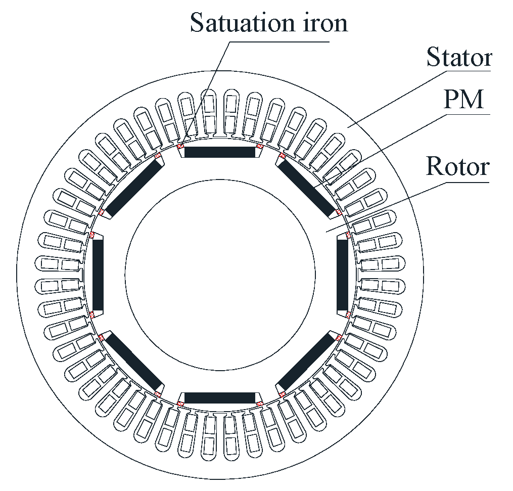
Figure 1 shows an interior permanent magnet motor. The rotor iron is partially saturated because the permanent magnet was inserted into the rotor. The assumptions of the infinite permeable iron material in the stator and the rotor except saturation iron area are used on the analytical model in this paper.
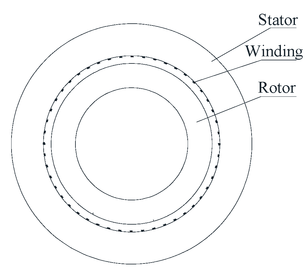
Analysis of the magnetic field in the IPMM is difficult due to the magnetic saturation in the rotor. The analytic formulas of the armature reaction magnetic field of IPMM can be derived as follows: (1) As shown in Figure 2, the armature reaction field distribution is obtained assuming a smooth airgap and without considering the interior permanent magnet. The solution of the simplified model has been discussed in the References [6,7]. To apply and understand this solution more conveniently and accurately, some coefficients in this solution have been revised, the solution details and results of the model have been extended in this paper. (2) A relative permeance function is introduced to account for the effect of the magnetic barrier t in the rotor.
2.1. The Armature Reaction Field Distribution of the Simplified Model
2.1.1. Magnetic Field Produced by a Coil
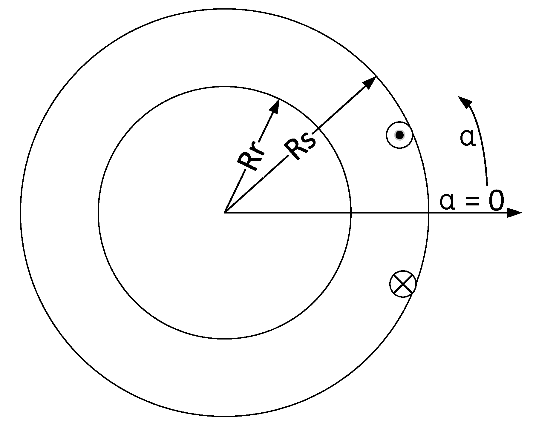
The simplified magnetic field model of a coil is shown in Figure 3. In polar coordinates, the governing Laplacian equation can be expressed as:
where r is the radius of the calculation air gap, α is the circumferential angle, ϕ is the vector magnetic potential.
Assuming that the permeability of the stator core and rotor hub is infinite, the boundary conditions to be satisfied are:
where J is the current density, i is the current of the coil, Rs is the stator inner radius, Rr is the rotor outer radius, b0 is the width of slot opening.
Since the general solution for ϕ(α,r) is:
And
where μ0 is the permeability of the vacuum.
Based on the current sheet model, the radial component of the magnetic flux density is derived as:
where Brv is the amplitude of the magnetic flux density, Q1 is the number of stator slots that a coil is covering, Qs is the number of stator slots.
2.1.2. Armature Reaction Field of 1-Phase Winding
According to the superposition method, the flux density of the one phase winding is derived.
where Kdυ is the winding distribution factor. For integer slot motors, Kdυ can be expressed as:
where q = Qs/2pm; p is the number of poles, m is the number of phases.
Taking an 8-pole 48-slot single-layer distributed winding as an example:
For cos (π + α) = −cosα, cos (2π + α) = cosα,
So, the Formula (12) can be simplified as:
Similarly, Equation (10) can be simplified as:
where N is the number of series turns per phase.
2.1.3. ARMF of 3-Phase Winding
There are significant harmonics contained in the phase winding current waveform of a brushless dc motor. These can be expressed as a Fourier series, viz:
where ωr is the electrical angular velocity, t is time, θu is the initial phase angle.
In a brushless dc motor, the flux density produced by 3-phase winding can be derived from (15) as:
where
Therefore,
where , , ,
- (1)
- While , , , v = 6c − 1
- (2)
- While , , , v = 6c + 1
2.2. Complex Relative Permeance in Rotor Motion Coordinate
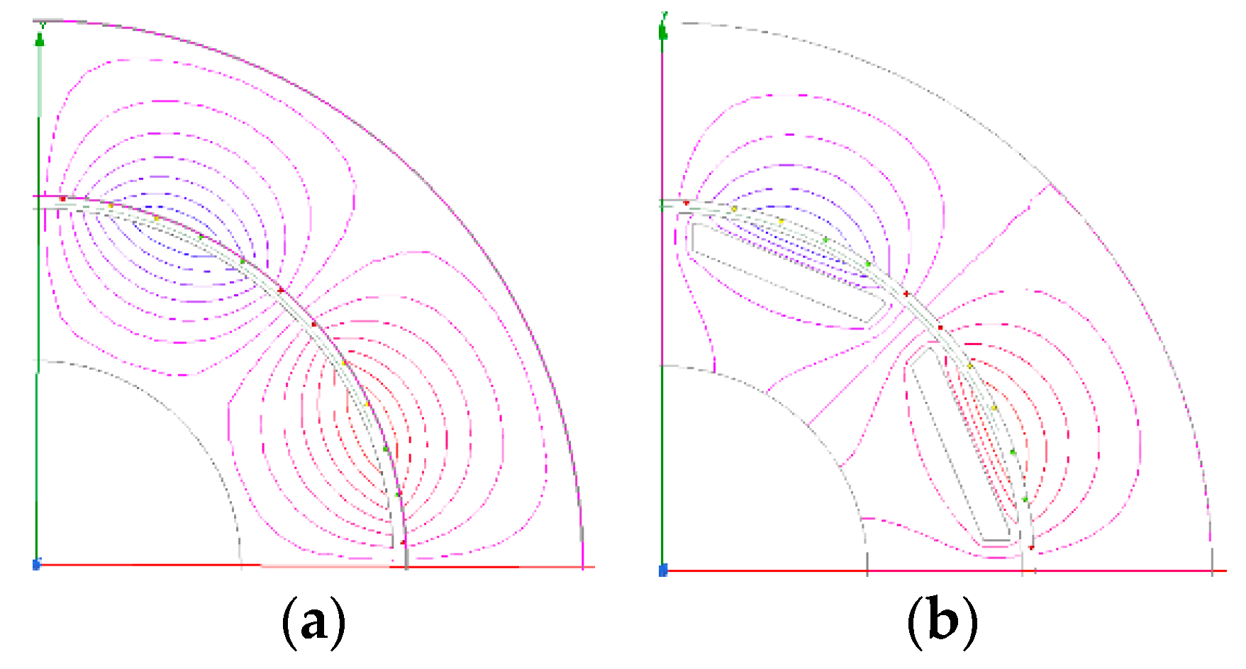
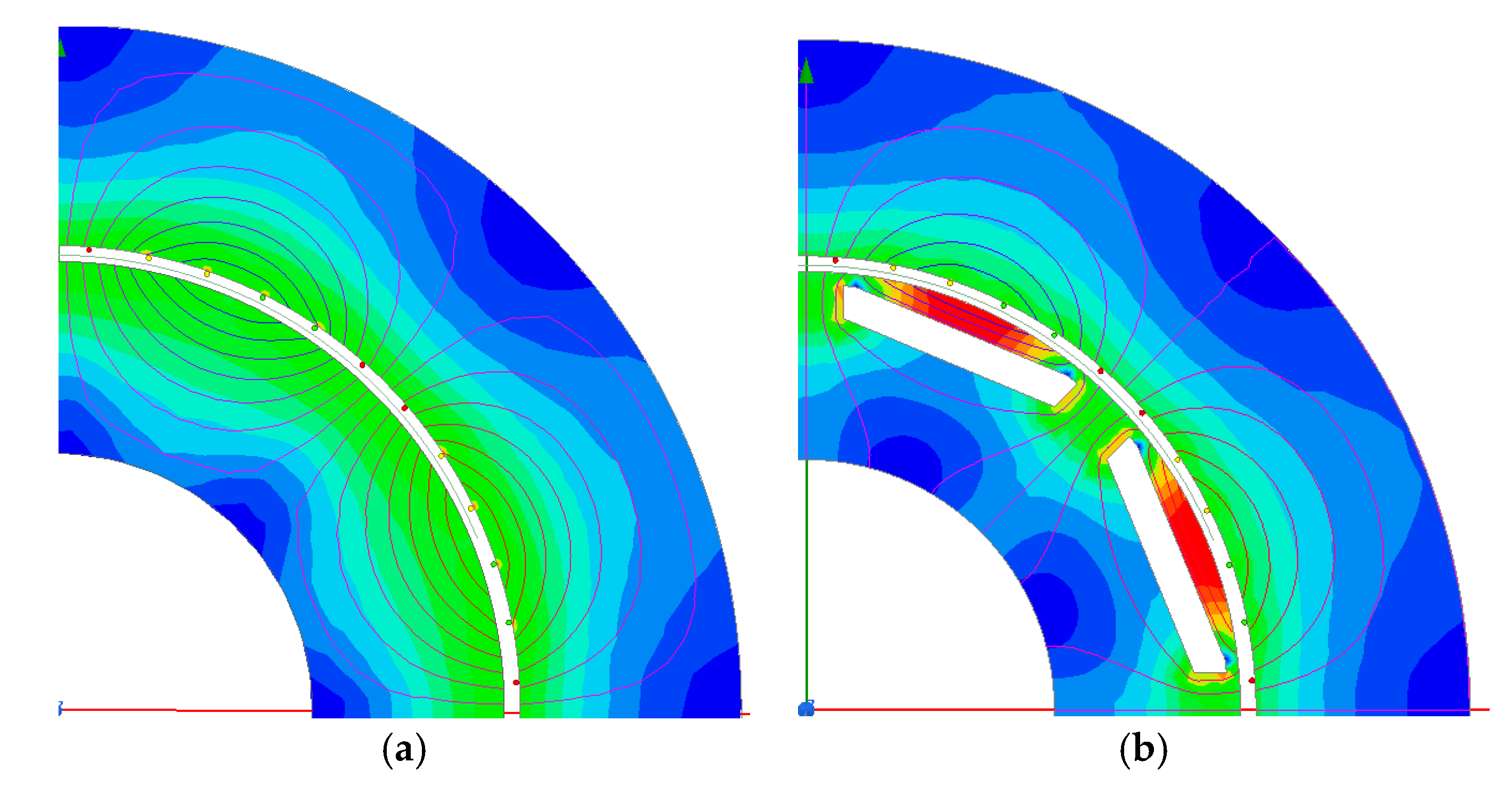
To calculate the airgap permeance per area unit, Reference [21] developed a numerical–analytical coupling model. To determine the fluctuations in the average airgap magnetic field caused by the rotor saturation of IPMM, two series of two magnetostatic FEs simulations are necessary as shown in Figure 4.
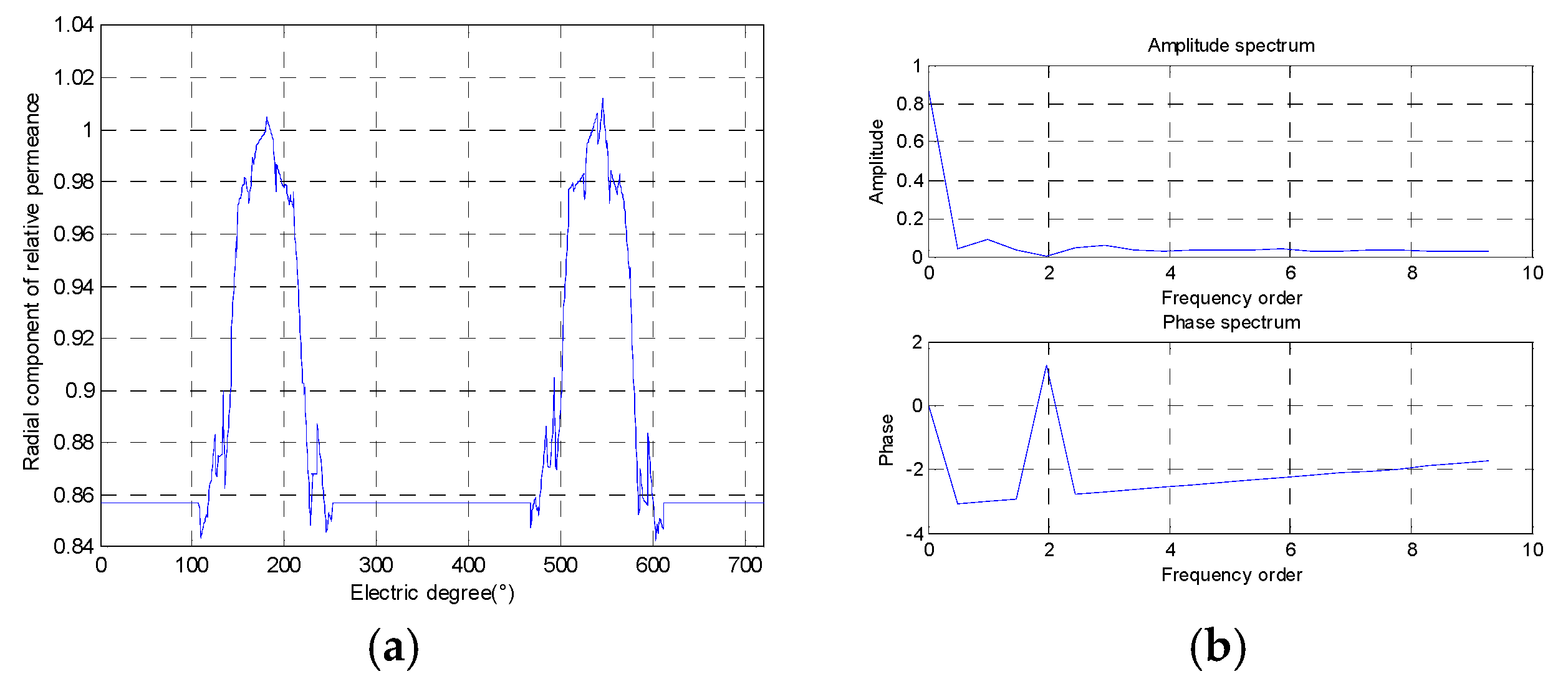
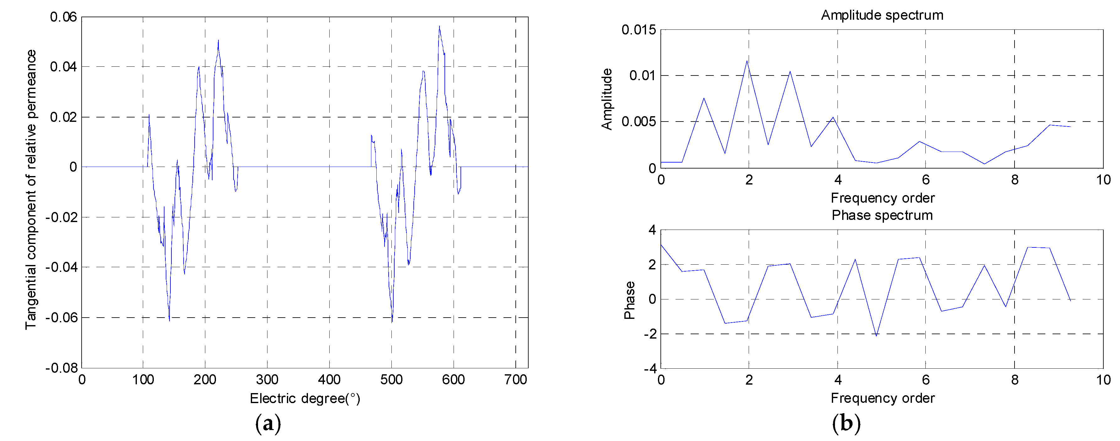
While unconsidering the influence of the magnetic barrier, the radial airgap magnetic flux density and tangential airgap magnetic flux density are calculated using the model shown in Figure 4a. While considering the influence of the magnetic barrier, the radial airgap magnetic flux density and tangential airgap magnetic flux density are calculated using the model shown in Figure 4b. The real (radial) and imaginary (tangential) parts of the global airgap permeance per unit can be expressed as:
where λreal and λimag are the radial and tangential components of relative permeance, Br_mb is the radial flux density with magnetic barrier, and Bθ_mb is the tangential flux density with a magnetic barrier, Br_unmb is the radial flux density without a magnetic barrier, and Bθ_unmb is the tangential flux density without a magnetic barrier. The relative permeances are calculated by (20) and (21).
2.3. Complex Relative Permeance in Stator Static Coordinate
The stator of the motor is stationary, but the rotor is rotated opposite the stator in the stator static coordinate. Therefore, the spatial angle and the time are both variables in the function of the complex relative permeance. Fourier series expansions of the λreal and λimag, in the stator static coordinate are:
where, an and bn is the amplitude of relative permeance.
2.4. Armature Reaction Field of IPMM
The radial airgap magnetic fields of IPMM are calculated in the stator static coordinate.
The spatial harmonic orders and time harmonic orders of the ARMF can be obtained from (26), as shown in Table 1.
3. Comparison with the Results of Finite-Element Calculation
Take an 8-pole-48-slot IPMM for example, a finite element model is established by the maxwell. Which is a kind of finite element software. The finite element model is used to verify the accuracy of the analytical model proposed in this paper. Table 2 shows the IPMM’s parameters. The material of the Iron core is M19-29G. To eliminate the effect of the permanent magnets on the armature-reaction field, the permanent magnets in the FEM are replaced by air. The calculation radius of airgap magnetic field is chosen close to the rotor surface to reduce the effect of the stator slots. To realize the effect of rotor saturation on airgap magnetic field, three models are adopted, which are the model unconsidering rotor saturation, the model considering rotor saturation in static rotor condition, and the model considering rotor saturation in rotating rotor condition. Finite-element simulation results are shown in Figure 7. The rotational speed is 3000 r/min, the current is 1000 A, the number of turns per slot in the stator is 1, the radius of calculation airgap is 71 mm.
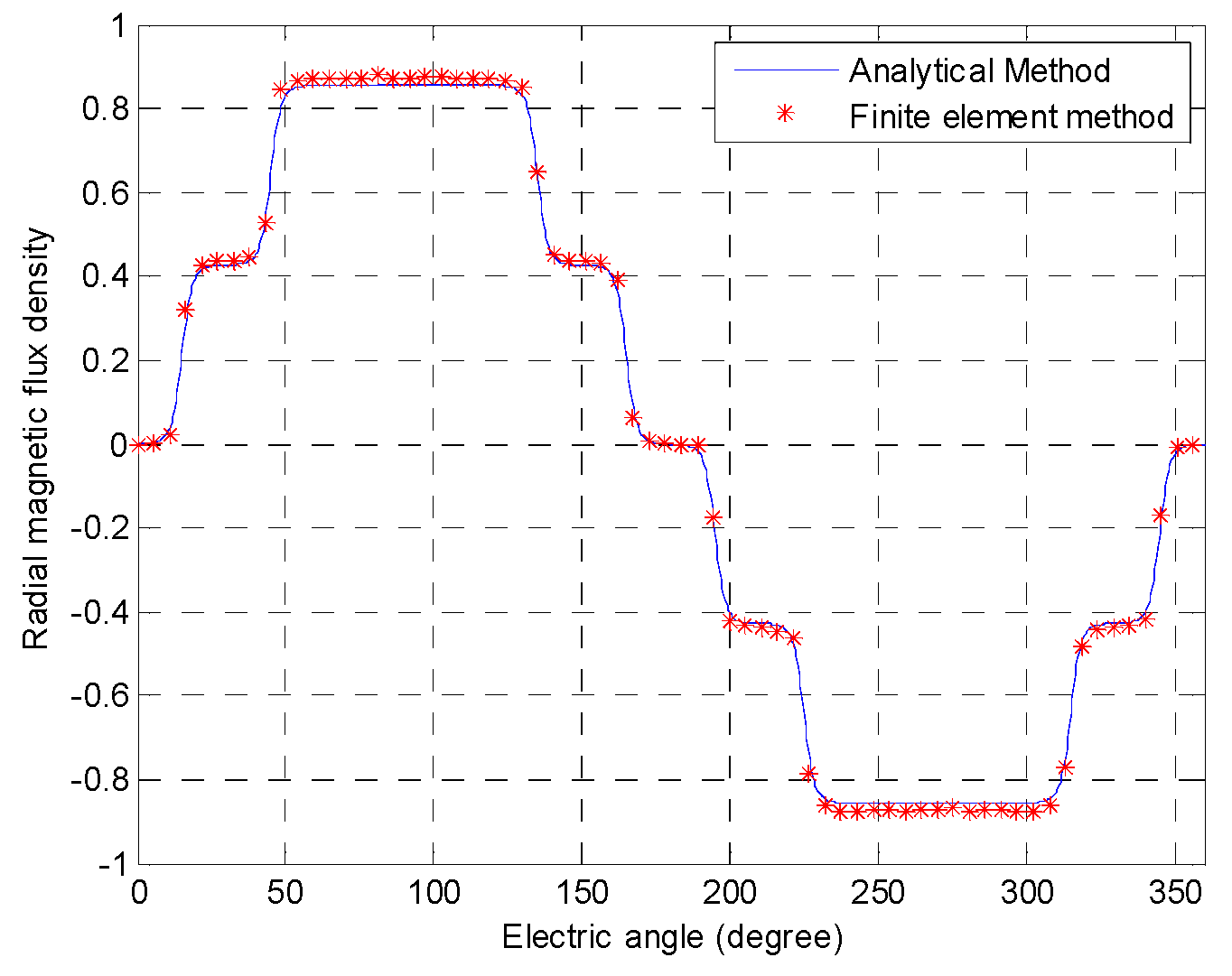
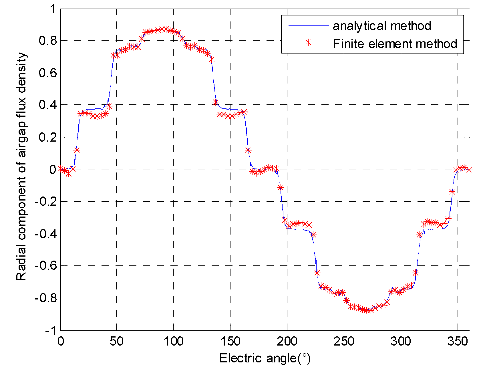
3.1. Verification of Analytical Method
As shown in Figure 8, the analytical model results are the same as the results of the finite element method without considering the magnetic barrier. As can be seen from Figure 9, while considering the magnetic barrier, there is a small error between the analytical model analysis results and the finite element calculation results, but most of them are consistent. The analytical results can reflect the spatial harmonic orders and time harmonic orders of the ARMF.
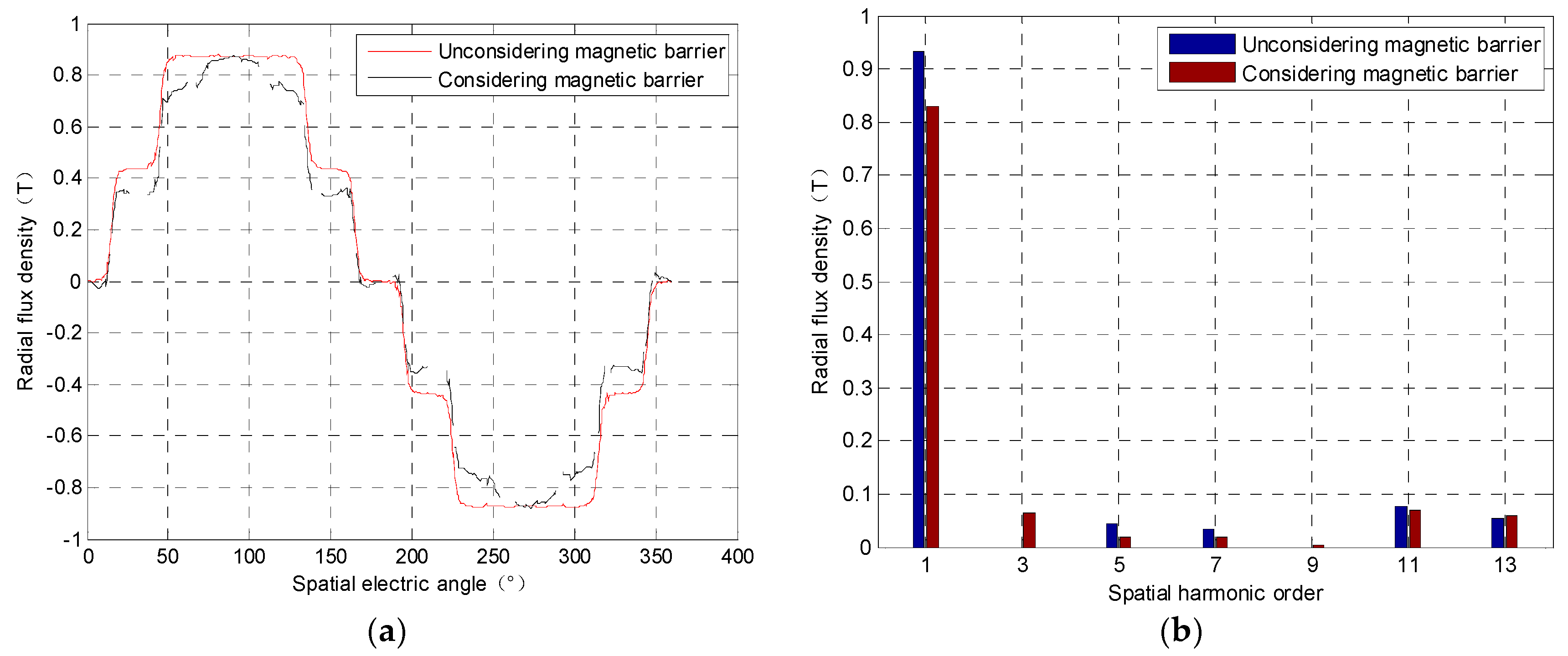
3.2. Spatial Order Distribution Characteristics
The spatial harmonic orders of the radial component of the flux density of ARMF are shown in Figure 10, which is obtained by FEM. Without considering the magnetic barrier, the spatial orders of armature reaction magnetic field are 1, 5, 7, 11… |6c ± 1|; while the magnetic barrier is considered, the spatial orders of armature reaction magnetic field are 1, 3, 5, 7, 11…. |6c ± 1 ± 2n|. These are consistent with the results of Table 1. And as can be seen from Figure 10, while considering interior permanent magnet, the fundamental component of the airgap magnetic field is significantly reduced, and there is a large third harmonic component. That is because the 0th harmonic and the 1st harmonic of the relative permeance have a great influence on the ARMF due to the saturation of the rotor.
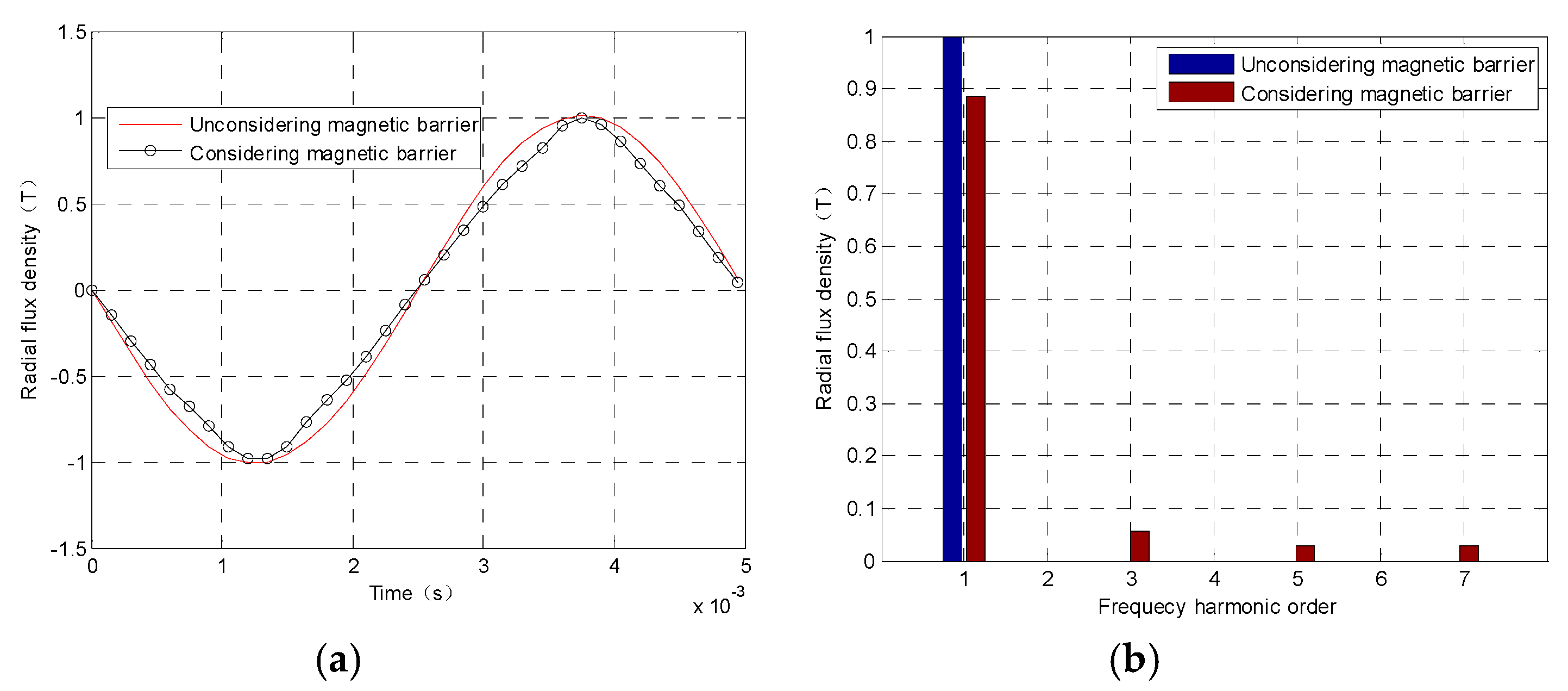
3.3. Frequency Distribution Characteristics
The frequency distribution characteristics of the radial magnetic flux density of the ARMF are shown in Figure 11, which is obtained by FEM. Without considering the magnetic barrier, the frequency order of the ARMF is 1 (u = 1); while the magnetic barrier is considered, the frequency orders of the armature reaction magnetic field are 1, 3, 5, 7…. |u ± 2n)|. These are consistent with the results of Table 1. And as shown in Figure 11, while considering the magnetic barrier, the fundamental component of the airgap magnetic field is significantly reduced, and there are large 3rd, 5th, and 7th harmonics components. That is because the 0th harmonic, 1st, and 3rd harmonic of the relative permeance have a great influence on the ARMF due to the saturation of the rotor.
4. Conclusions
This paper provides a calculation method of the armature reaction magnetic field (ARMF) of an IPMM. The analytical model results are consistent with the finite element results. The influence of the magnetic barrier on the armature reaction field is analyzed by the proposed analytical model. The spatial harmonic orders and time harmonic orders of the ARMF of IPMM are revealed respectively.
(1) Without considering the magnetic barrier, the spatial orders of ARMF are |6c ± 1|; while the magnetic barrier is considered, the spatial orders of ARMF are |6c ± 1 ± 2n|. For spatial order distribution characteristics of an IPMM, the fundamental component of the airgap magnetic field is significantly reduced, and there is a large 3rd harmonic component. That is because the 0th harmonic and the 1st harmonic of the relative permeance have a great influence on the ARMF due to the saturation of the rotor.
(2) Without considering the magnetic barrier, the frequency orders of the ARMF is |u|; while the magnetic barrier is considered, the frequency orders of the armature reaction magnetic field are |u ± 2n|. For frequency distribution characteristics of an IPMM, the fundamental component of the airgap magnetic field is significantly reduced, and there is a large 3rd, 5th, and 7th harmonics components. That is because the 0th harmonic, 1st, and 3rd harmonic of the relative permeance have a great influence on the ARMF due to the saturation of the rotor.
Author Contributions
Data curation, H.Y.; Funding acquisition, F.M.; Investigation, H.Y.; Methodology, H.Y.; Project administration, F.M.; Resources, C.G.; Software, H.Y.; Supervision, L.W. (Liang Wu); Validation, L.W. (Lulu Wei); Visualization, L.W. (Lulu Wei) and C.G.; Writing—original draft, H.Y.; Writing—review & editing, L.W. (Lulu Wei) and H.Y.
Funding
This research was funded by [National Science Foundation of China] grant number [51705185].
Conflicts of Interest
The authors declares no conflict of interest.
References
- Wang, X.; Xu, S.; Li, C.; Li, X. Field-Weakening Performance Improvement of the Yokeless and Segmented Armature Axial Flux Motor for Electric Vehicles. Energies 2017, 10, 1492. [Google Scholar] [CrossRef]
- Zhao, J.; Yan, Y.; Li, B.; Liu, X.; Chen, Z. Influence of different rotor teeth shapes on the performance of flux switching permanent magnet machines used for electric vehicles. Energies 2014, 7, 8056–8075. [Google Scholar] [CrossRef]
- Ma, F.; Yin, H.; Wei, L.; Tian, G.; Gao, H. Design and Optimization of IPM Motor Considering Flux Weakening Capability and Vibration for Electric Vehicle Applications. Sustainability 2018, 10, 1533. [Google Scholar] [CrossRef]
- Liu, X.; Gu, Z.; Zhao, J. Torque ripple reduction of a novel modular arc-linear flux-switching permanent-magnet motor with rotor step skewing. Energies 2016, 9, 404. [Google Scholar] [CrossRef]
- Li, Y.; Chai, F.; Song, Z.; Li, Z. Analysis of Vibrations in Interior Permanent Magnet Synchronous Motors Considering Air-Gap Deformation. Energies 2017, 10, 1259. [Google Scholar] [CrossRef]
- Zhu, Z.Q.; Howe, D.; Bolte, E.; Ackermann, B. Instantaneous magnetic field distribution in brushless permanent magnet DC motors. I. Open-circuit field. IEEE Trans. Magn. 1993, 29, 124–135. [Google Scholar] [CrossRef]
- Zhu, Z.Q.; Howe, D. Instantaneous magnetic field distribution in brushless permanent magnet DC motors. II: Armature-Reaction Field. IEEE Trans. Magn. 1993, 29, 136–142. [Google Scholar] [CrossRef]
- Zhu, Z.Q.; Howe, D. Instantaneous magnetic field distribution in brushless permanent magnet DC motors. IV: Magnetic Field on Load. IEEE Trans. Magn. 1993, 29, 152–158. [Google Scholar] [CrossRef]
- Zhu, Z.Q.; Howe, D.; Chan, C.C. Improved analytical model for predicting the magnetic field distribution in brushless permanent-magnet machines. IEEE Trans. Magn. 2002, 38, 229–238. [Google Scholar] [CrossRef] [Green Version]
- Zhu, Z.Q.; Howe, D. Instantaneous magnetic field distribution in brushless permanent magnet DC motors. III: Effect of stator slotting. IEEE Trans. Magn. 1993, 29, 143–151. [Google Scholar] [CrossRef]
- Zhu, Z.Q.; Xia, Z.P.; Wu, L.J.; Jewell, G.W. Analytical Modeling and Finite-Element Computation of Radial Vibration Force in Fractional-Slot Permanent-Magnet Brushless Machines. IEEE Trans. Ind. Appl. 2010, 46, 1908–1918. [Google Scholar] [CrossRef]
- Zarko, D.; Ban, D.; Lipo, T.A. Analytical calculation of magnetic field distribution in the slotted air gap of a surface permanent-magnet motor using complex relative air-gap permeance. IEEE Trans. Magn. 2006, 42, 1828–1837. [Google Scholar] [CrossRef]
- Ma, C.; Chen, C.; Li, Q.; Gao, H.; Kang, Q.; Fang, J.; Cui, H.; Teng, K.; Lv, X. Analytical Calculation of No-Load Magnetic Field of External Rotor Permanent Magnet Brushless Direct Current Motor Used as In-Wheel Motor of Electric Vehicle. IEEE Trans. Magn. 2018, 54, 1–6. [Google Scholar] [CrossRef]
- Verez, G.; Barakat, G.; Amara, Y.; Hoblos, G. Impact of Pole and Slot Combination on Vibrations and Noise of Electromagnetic Origins in Permanent Magnet Synchronous Motors. IEEE Trans. Magn. 2015, 51, 1–4. [Google Scholar] [CrossRef]
- Valavi, M.; Nysveen, A.; Nilssen, R.; Lorenz, R.D.; Rølvåg, T. Influence of Pole and Slot Combinations on Magnetic Forces and Vibration in Low-Speed PM Wind Generators. IEEE Trans. Magn. 2014, 50, 1–11. [Google Scholar] [CrossRef]
- Min, S.G.; Sarlioglu, B. Modeling and Investigation on Electromagnetic Noise in PM Motors with Single and Double Layer Concentrated Winding for EV and HEV Application. IEEE Trans. Transp. Electrif. 2018, 4, 292–302. [Google Scholar] [CrossRef]
- Ma, J.; Zhu, Z.Q. Unbalanced Magnetic Force Mitigation in 3-slot/2-pole Permanent Magnet Machine by Inserting Auxiliary Slots. In Proceedings of the 2017 IEEE International Electric Machines and Drives Conference (IEMDC), Miami, FL, USA, 21–24 May 2017; pp. 1–8. [Google Scholar]
- Valavi, M.; le Besnerais, J.; Nysveen, A. An Investigation of Zeroth-Order Radial Magnetic Forces in Low-Speed Surface-Mounted Permanent Magnet Machines. IEEE Trans. Magn. 2016, 52, 8107206. [Google Scholar] [CrossRef]
- Zhu, Z.Q.; Jamil, M.L.M.; Wu, L.J. Influence of Slot and Pole Number Combinations on Unbalanced Magnetic Force in PM Machines with Diametrically Asymmetric Windings. IEEE Trans. Ind. Appl. 2013, 49, 9–30. [Google Scholar] [CrossRef]
- Valavi, M.; Nysveen, A.; Nilssen, R. Effects of Loading and Slot Harmonic on Radial Magnetic Forces in Low-Speed Permanent Magnet Machine with Concentrated Windings. IEEE Trans. Magn. 2015, 51, 1–10. [Google Scholar] [CrossRef]
- Fakam, M.; Hecquet, M.; Lanfranchi, V.; Randria, A. Design and Magnetic Noise Reduction of the Surface Permanent Magnet Synchronous Machine Using Complex Air-Gap Permeance. IEEE Trans. Magn. 2015, 51, 1–9. [Google Scholar] [CrossRef] [Green Version]
Figure 1.
Interior permanent magnet motor (IPMM).

Figure 2.
Simplified model of IPMM.

Figure 3.
Distributed current sheet model of coil.

Figure 4.
Finite element (FE) simulations of airgap permeance (a) motor without magnetic barrier (b) motor with a magnetic barrier.
Figure 4.
Finite element (FE) simulations of airgap permeance (a) motor without magnetic barrier (b) motor with a magnetic barrier.

Figure 5.
Radial component of relative permeance: (a) Curve of relative permeance; (b) FFT analysis.
Figure 5.
Radial component of relative permeance: (a) Curve of relative permeance; (b) FFT analysis.

Figure 6.
Tangential component of relative permeance: (a) Curve of relative permeance; (b) FFT analysis.
Figure 6.
Tangential component of relative permeance: (a) Curve of relative permeance; (b) FFT analysis.

Figure 7.
Finite-element simulation model. (a) motor without magnetic barrier; (b) motor with a magnetic barrier.
Figure 7.
Finite-element simulation model. (a) motor without magnetic barrier; (b) motor with a magnetic barrier.

Figure 8.
Radial magnetic flux density of armature reaction field without a magnetic barrier.

Figure 9.
Radial magnetic flux density of armature reaction field considering the magnetic barrier.

Figure 10.
Spatial order distribution characteristics of the radial magnetic flux density of armature reaction field (Calculation with finite element model (FEM)). (a) radial flux density; (b) Fourier transform of radial flux density.
Figure 10.
Spatial order distribution characteristics of the radial magnetic flux density of armature reaction field (Calculation with finite element model (FEM)). (a) radial flux density; (b) Fourier transform of radial flux density.

Figure 11.
Frequency distribution characteristics of radial magnetic flux density of armature reaction field (Calculation with FEM). (a) radial flux density; (b) Fourier transform of radial flux density.
Figure 11.
Frequency distribution characteristics of radial magnetic flux density of armature reaction field (Calculation with FEM). (a) radial flux density; (b) Fourier transform of radial flux density.


Table 1.
The spatial harmonic orders and time harmonic orders of the armature reaction magnetic field (ARMF).
Table 1.
The spatial harmonic orders and time harmonic orders of the armature reaction magnetic field (ARMF).
| Items | Amplitude | Spatial Order | Time Order |
|---|---|---|---|
| Radial airgap magnetic fields unconsidering magnetic saturation | (6c ± 1) | u | |
| Complex relative permeance in stator static coordinate | an | 2n | 2n |
| Radial airgap magnetic fields considering magnetic saturation | (6c ± 1) ± 2n | u ± 2n |
Table 2.
The 8-pole-48-slot IPMM parameters.
| Items | Unit | Value |
|---|---|---|
| Number of stator slots | - | 48 |
| Number of rotor poles | - | 8 |
| Stator outer diameter | mm | 214 |
| Stator inner diameter | mm | 145 |
| Airgap length | mm | 0.9 |
| Rotor outer diameter | mm | 140 |
| Rotor inner diameter | mm | 100 |
| Iron core material | - | M19-29G |
| Rotational speed | rpm | 3000 |
| Amplitude of the current | A | 1000 |
| The conductors per slot | - | 1 |
© 2018 by the authors. Licensee MDPI, Basel, Switzerland. This article is an open access article distributed under the terms and conditions of the Creative Commons Attribution (CC BY) license (http://creativecommons.org/licenses/by/4.0/).
Share and Cite
MDPI and ACS Style
Ma, F.; Yin, H.; Wei, L.; Wu, L.; Gu, C. Analytical Calculation of Armature Reaction Field of the Interior Permanent Magnet Motor. Energies 2018, 11, 2375. https://doi.org/10.3390/en11092375
AMA Style
Ma F, Yin H, Wei L, Wu L, Gu C. Analytical Calculation of Armature Reaction Field of the Interior Permanent Magnet Motor. Energies. 2018; 11(9):2375. https://doi.org/10.3390/en11092375
Chicago/Turabian StyleMa, Fangwu, Hongbin Yin, Lulu Wei, Liang Wu, and Cansong Gu. 2018. "Analytical Calculation of Armature Reaction Field of the Interior Permanent Magnet Motor" Energies 11, no. 9: 2375. https://doi.org/10.3390/en11092375
Note that from the first issue of 2016, this journal uses article numbers instead of page numbers. See further details here.