1. Introduction
1.1. Motivation and Literature Review
The architecture of future power systems will change significantly, shifting from the centralized paradigm of production to the decentralized concept of a large number of prosumers enabling the transition to flexible low-carbon-energy systems [
1]. This large number of interactive distributed units creates new technical challenges in deploying different Smart Grid concepts such as virtual power plants [
2], microgrids [
3], or digital substations [
4]. The continuous development of communication technologies in terms of speed, reliability, and flexibility made it possible to transform traditional substation wiring into a completely digital environment. Although basic communication technologies were used in substations since the 1980s, their implementation was focused on signal exchange between the bay and station level and between station level and dispatching centers. Communication protocols were mostly manufacturer-dependent, and system interoperability between various devices, in particular between devices from different manufacturers, was extremely difficult.
Only by introducing the IEC 61850 Communication Networks and Systems in Substations [
5] set of standards have communication barriers been removed and interoperability on all station levels was enabled. By defining standardized communication blocks, data exchange on the bay level is eliminating the need for excessive bay cabling and wiring, completely shifting the design and interlocking logic to a new approach.
With an even bigger impact on substation and equipment design, communication on the process bus introduced the potential for completely digitalized substations. Primary switching equipment, such as circuit breakers and disconnectors, could be directly connected to the communication system and thus controlled and monitored completely as an intelligent electronics device (IED). According to the IEC 61850-9-2, analog representation of voltage and current in the primary circuit can be represented via sampled values, forming a continuous data stream in the communication network, available for further processing to all IEDs connected to the same network [
6]. As the original edition of the standard did not include the description of implemented data models, data sets, sampling rates, transmission rates, and time-synchronization methods, the UCA International Users Group created implementation guidelines that define a subset of IEC 61850-9-2, also known as IEC 61850-9-2LE. The guidelines are not a completely new standard, but rather an extended set of technical requirements set up to avoid interoperability issues [
7].
1.2. Contributions
Although foundation for a completely digital substation exists, the current state of technology is not there yet. With numerous technical challenges, and various intermediate steps and attempts, there is still a lot of research and development to be done to achieve the digital substation. The focus of this paper is to analyze the potential and limitations of sampled values in digitalized substation and hybrid substations by use of merging units or even protection relays. The paper provides several contributions:
An extended simulation-environment mathematical model of the IEEE 123-node bus test system has been developed, capable of simulating various fault current and voltage waveforms to test digital representations in sampled values.
A laboratory hardware-in-the-loop test bed has been developed with traditional current- and voltage-operated protection relays as well as protection functions operated by sampled values according to IEC 61850-9-2LE.
To support the results, a large number of test sequences have been performed. Statistical analysis of digital and analog performance supports the conclusions of the paper, demonstrating the usefulness of the proposed test bed in identifying the benefits of process-bus data digitalization.
2. IEC 61850 Standard Basics
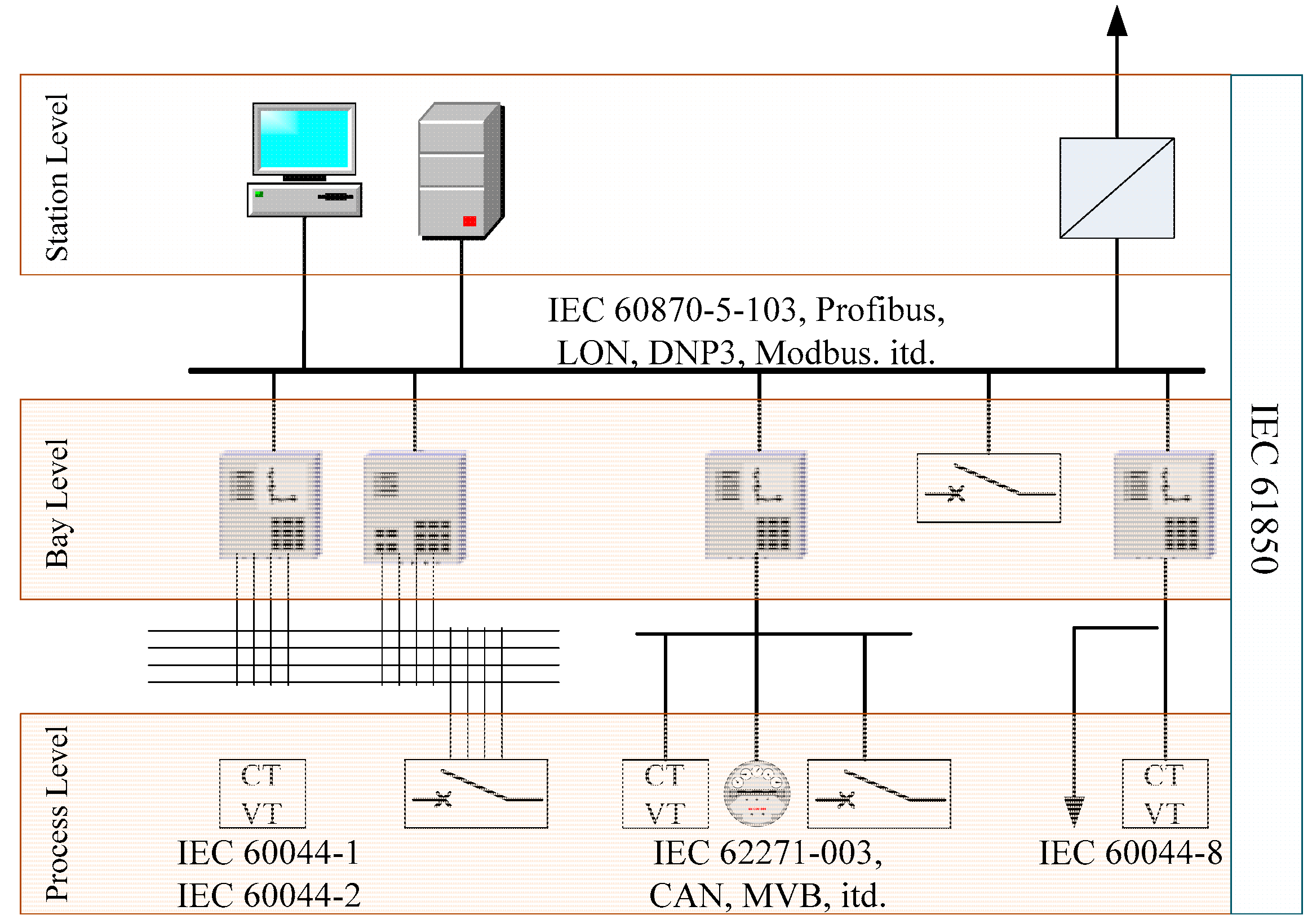
Today’s substation automation systems include three hierarchal levels: the substation level, bay level, and process level. Before the introduction of the IEC 61850, there was no comprehensive communication standard covering all substation levels; thus, information exchange between the levels was performed with incompatible standards that had to be adapted by implementing various protocol gateways or simplified binary or analog information exchange. Some of the basic standards used in substations are shown in
Figure 1.
Data exchange according to standard IEC 61850 is performed on an Ethernet data-link layer, which was enabled by continuous development of network technology in terms of speed and reliability. Ethernet network topology has had significant impact on overall communication performance. The five basic topology types used in substations are: (a) bus topology; (b) ring topology; (c) star topology; (d) multiple-star topology; and (e) ring-star topology. Depending on network topology, it is possible to incorporate advanced communication functions like network redundancy and enhanced speed and reliability.
Object-oriented substation modeling, according to IEC 61850, is based on logical nodes that represent the smallest functional object that can receive and send data [
8]. Logical nodes are standardized function blocks organized and defined with alphanumeric characters (e.g., PTOC—protection time over current), wherein the first sign indicates the logical node group. Two main logical node groups are:
Although the initial standard was created for communication networks within substations, due to its flexible and expandable data structure, the application has since spread to various industries (e.g., oil and gas, renewables, and hydropower plants) creating numerous application-specific logical notes [
9].
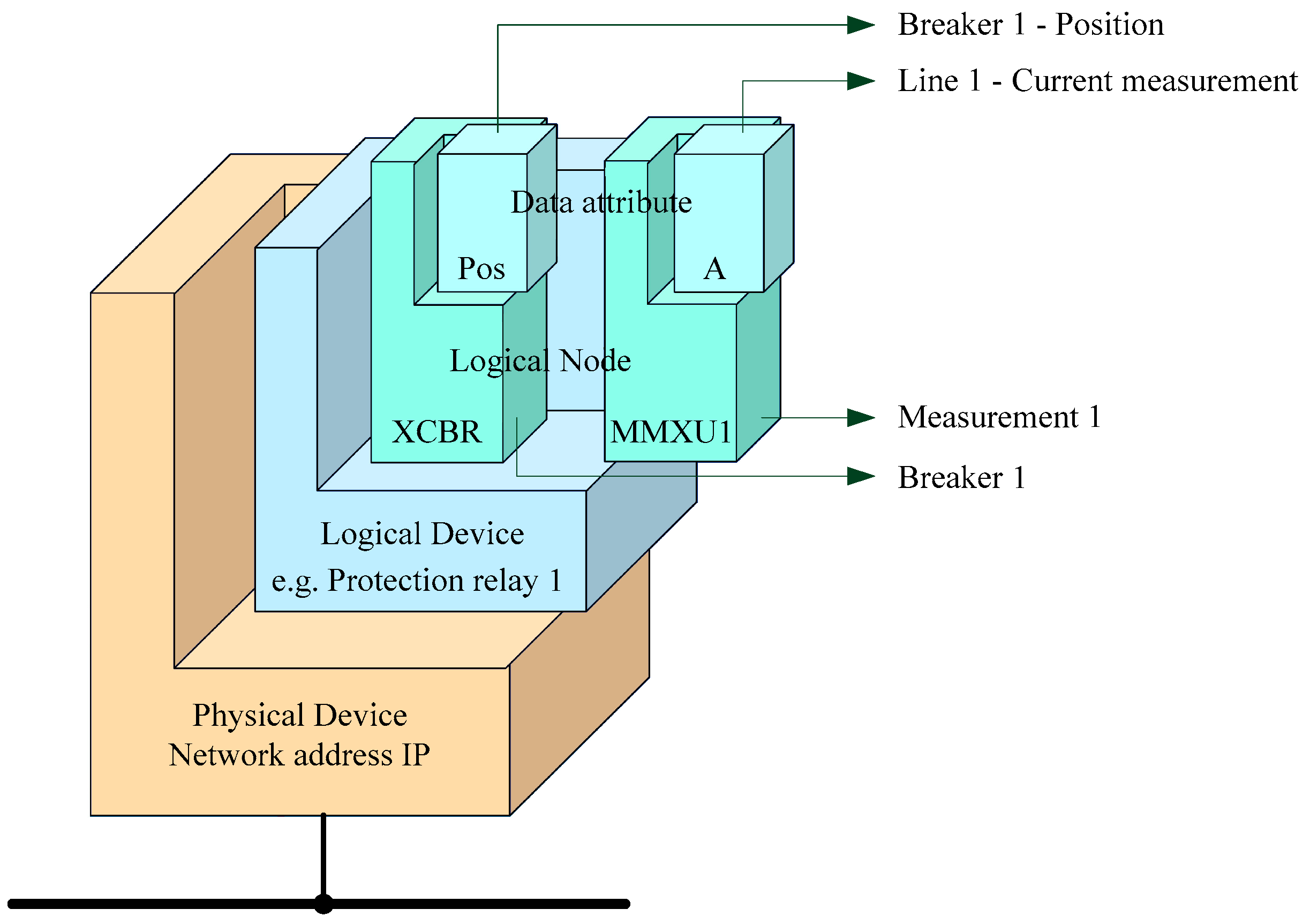
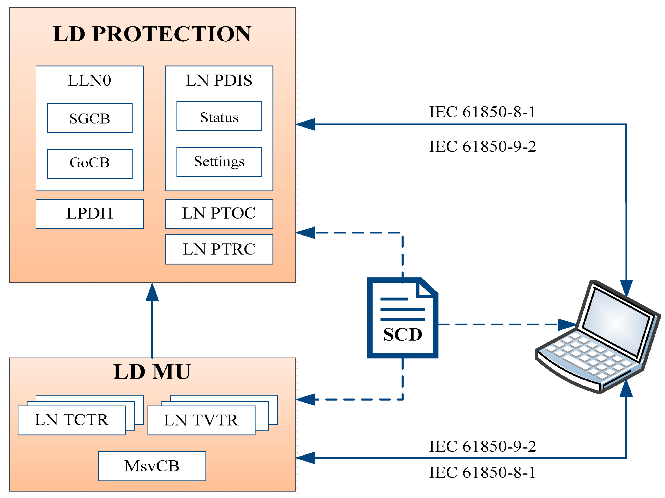
All intelligent electronic devices are represented by a physical device that performs numerical calculations, emulating logical devices that are the representation of function-related logical devices. On a single physical device, it is possible, and even common, to incorporate a series of grouped logic devices. A simplified illustration of the data models according to IEC 61850 is given in
Figure 2 [
10].
In addition to the function defining data structure, the standard IEC 61850 defines groups of communication mechanisms for information exchange as: 1—sampled values, 2—generic object-oriented substation event (GOOSE) messages, 3—time synchronization, and 4—vertical communication. As Ethernet technology is the underlying data-link layer, communication is inherently nondeterministic; hence, it introduces a certain level of communication uncertainty. However, to ensure proper and timely action of the control, protection, and monitoring functions in substations, a priority tag is added to every data packet on the communication bus [
9]. These priority tags enable network elements to transfer data with the highest priority first, ensuring that signals like “Trip” to arrive at the designation within the maximum transfer-time limit defined by the standard. The most widely used group within the IEC 61850 is GOOSE messages. This is an extremely flexible tool as it is an event-triggered data-exchange event transferred from and to all station levels that can contain binary states or even analog values [
11].
However, the exchange of measured data values, in terms of sampled values of primary voltage and current, has not been extended to practice, with the exception of pilot projects and proof of concept projects. The data exchange of sampled values is based on the principle of publisher and subscriber. Measurement transformers or merging units digitalize analog values and store/publish them in the output buffer, making them available to any subscriber on the network. Each sampled-value data package is marked with a time tag in order to form a continuous stream of measured values. A sampled-value control (SVC) system is introduced to control the data stream from the publisher output buffer to the subscriber input buffer [
12,
13]. Two types of sample-value models are used:
For protection functions: a stream of 80 samples per cycle is used (4000 samples/s).
For power-quality measurement functions: a stream of 256 samples per cycle is used (12,800 samples/s) in data blocks of eight samples, resulting in 32 data blocks per cycle.
The time needed to generate and transmit information from and to IED on the network is defined with the following equation:
tp: total time needed to generate and transmit information;
ta: time needed to save the data to the outgoing buffer of the publisher;
tb: time delay caused by the network communication system;
tc: time needed to save the data to the incoming buffer of the subscriber.
The IEC 61850 standard defines the requirements and methods for statistical analysis of total data transition time with the corresponding standard deviation. The standard defines the standard deviation with the Gauss distribution [
14]:
It has been confirmed that data transmission time in 99.99% of the tested cases is shorter than 1 ms, while it has been shown that, in the sample of 250,000 data packages, the actual distribution of standard deviation is significantly lower than required by the standard [
15]. A large number of IEDs support diagnostic reports of GOOSE messages, which makes it simple to perform statistical analyses of received and sent data. It should be mentioned that no additional hardware or IED configurations are needed to extract the diagnostic reports, making this a practical tool and basis for analyses of the communication system in IEC 61850 [
16].
3. Testing of Numerical-Protection Relays
Numerical protection relays in traditional substation topologies determine the state of a protected object or zone based on the analog measured values of current and voltage. In case of a fault state of the protected object or zone, protection relays activate tripping signals in order to isolate the fault as fast as possible and as close to the fault as possible. As already mentioned before, digitalized substations do not use analog values of current and voltage obtained by measurement, but rather sampled values that are the representation of the substation primary circuit.
Testing of traditional numerical relays is performed by simulating faults in the grid condition by generating fault values for voltage and current by using secondary injection-test instruments. Depending on the programmed configuration of the relay, the test instrument can monitor binary outputs or the communication signals of the tested object. The test is performed by a protection-relay specialist who must have profound knowledge of the power grid and protection-relay operation. All test sequences are managed and monitored by the protection relay specialist, making them a key figure in terms of periodical testing of protection relays [
17].
Unlike traditional substation topologies, information exchange on IEC 61850-based digital substations is completely performed on the Ethernet bus, so the test tool differs significantly and introduces new possibilities. Traditional secondary test instruments are obsolete in a digital-substation configuration as all signals are simulated virtually. Simulated test values of current, voltage, and binary states can be generated by newly developed IEC 61850-based simulator test sets or PC workstations, connected only to the station communication network. Faulty currents and voltages are simulated with a sampled value stream and trip actions in terms of GOOSE messages of the tested relay are monitored on the communication bus. The test approach in digital and traditional substations is the same, but the test medium is changed [
18].
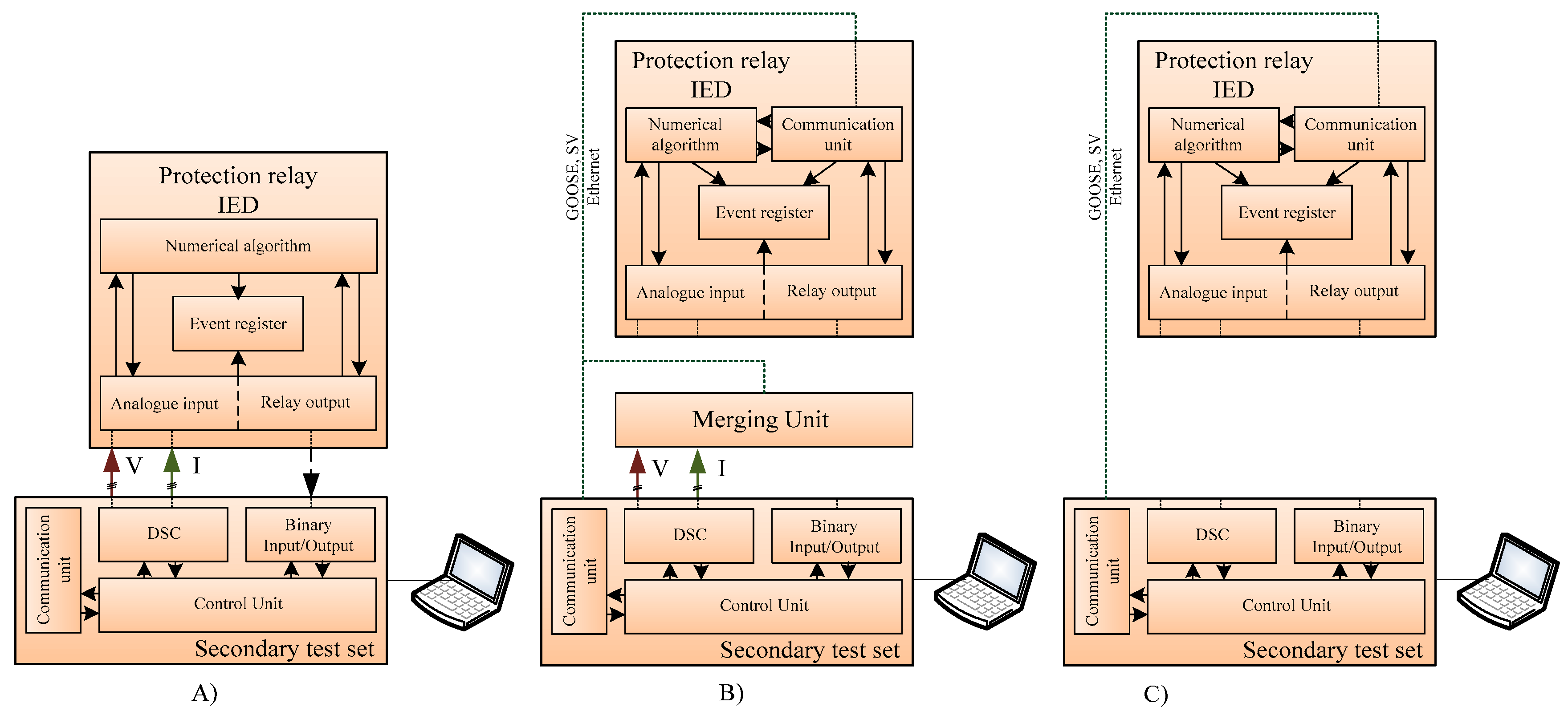
For the testing of local and distribution protection function blocks in numerical protection relays, besides current and voltage simulation, information of the relay configuration and the protection parameter settings is necessary. Although every protection-relay manufacturer has developed their own support software for protection-relay programming and setting, with the introduction of IEC 61850, relay manufacturers have the possibility to display the relay settings within the relays’ configured description file. Basic testing topology of traditional, digital, and hybrid substations is shown in
Figure 3 below.
The IEC 61850 standard introduces a description code for the configuration of substations (SCL—substation configuration language) [
19], which is manufacturer-independent and enables interoperability between various IEDs. The standard introduces four types of description files:
ICD—IED capability description;
CID—Configured IED description;
SSD—System specification description;
SCD—System configuration description.
The substation configuration-description language is XML (eXtensible markup language) code, which is not compliable, but serves only as a description structure [
20].
4. Testing Environment for Intelligent Electronic Devices
To determine the potential and limitations of numerical protection relays in digital substations as compared to traditional substations, hardware in the loop model has been developed that incorporates a MATLAB-based grid-fault simulation in combination with a secondary voltage- and current-injection test set and a sampled-values test set. To improve fault-state simulation and bring relay reaction closer to real-time grid operations, an extended IEEE 123-node test feeder has been implemented to realistically simulate current and voltage waveforms.
4.1. IEEE Distribution Test Feeder
Common test systems have been widely used by researchers to provide standardized test beds for new algorithms, protection, and control schemes as a way of independent verifications and test replications. The first IEEE test environment was introduced in 1991, and initially there were four test feeders, used primarily to check the accuracy of power-flow analyses. There are no comparisons of the results of short-circuit studies. The original four test feeders were [
21]:
13-node test feeder represents a highly loaded test feeder for simulations of power-flow convergence in a highly unbalanced system;
34-node test feeder represents an actual distribution network grid in Arizona with very long feeder requiring the application of voltage regulators;
37-node test feeder represents an actual distribution network in California with a three-wire delta line configuration;
123-node test feeder represents common characteristics in a large distribution network consisting of overhead lines and underground cables.
Additional test feeders have been developed, and various expansions and improvement of the initial test feeders have been added for special applications, e.g., for testing the impact of a distributed generation [
22].
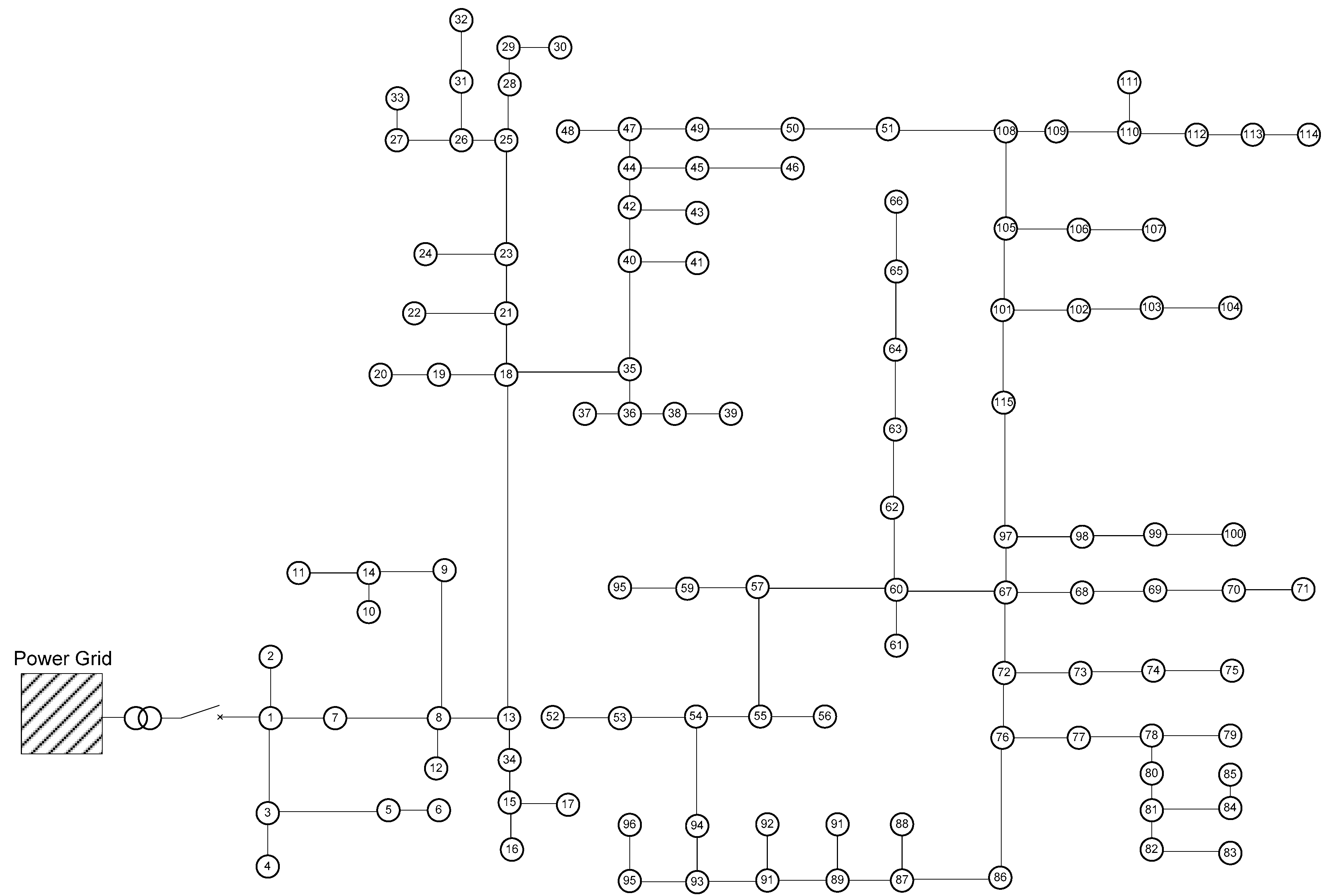
For the test purposes of this paper, a modified version of the IEEE 123-node test feeder was developed. To enable the use of simulated fault currents and voltages for protection relay-testing purposes, the IEEE 123-node test feeder was switched from the initial 60 Hz system to a 50 Hz system. Additional modifications include the elimination of the stabilization transformer from the initial topology and adding more generation units, which represent a more modern distribution grid with distributed energy resources. A simplified illustration of the IEEE test model is shown in
Figure 4.
Unlike the initial IEEE 123-node model, which was developed for power-flow analysis, the extended short-circuit analysis model is capable of analyzing all possible types of short circuits at all nodes. All model parameters, including source and fault impedances, have been defined by the revised IEEE model [
23].
In this paper, test-bed modeling has been performed in a MathWorks Simulink R2016a (MathWorks, Natick, MA, USA) environment. To be able to extract and analyze the simulation results for the generation of transient power-system disturbances in a COMTRADE format, the discrete execution time of the simulation was adjusted to the sample rate of process bus-sampled values of 4000 Hz.
4.2. Testing Environment-Sampled Value Communication
Digitalized substations according to IEC 61850 include a data exchange between the bay and process level, not only for status signals and commands, but also for measured currents and voltages. Only a few fully digitalized substations are completed as pilot projects. Primary equipment with inbuilt communication capabilities is not market-ready, meaning that, currently, the use of external digitalization equipment is necessary. In those substations, merging units are IEDs that can monitor binary input and control binary output in order to digitalize binary signals on the process level. They can be installed in marshaling kiosks to avoid excessive cable routing from the process level to the bay level, as they can send and receive binary data over the IEC 61850 communication port [
24].
Another type of merging unit digitalizes currents and voltages from the measurement transformers. They are connected to the secondary sides of the voltage and current transformers and publish the voltage and current values as sampled-value Ethernet packets. Digitalized analog data is transferred by optic fiber or twisted pair cables to receiving protection relays (IEDs) via an IEC 61850 process bus, and a data packet that includes sampled values, GOOSE messages, and precision time protocol (PTP) [
25]. IEDs are connected to the process bus by Ethernet switches.
For the testing purposes of this paper, hardware in the loop model has been developed that represents three development stages of the substation topology as shown in
Figure 3:
traditional topology with currents and voltages being physically measured by the protection relay;
hybrid topology with currents and voltages being digitalized in the merging unit and transferred to the protection relay via communication bus; and
digitalized topology with current and voltage being directly transferred to the protection relay via communication bus.
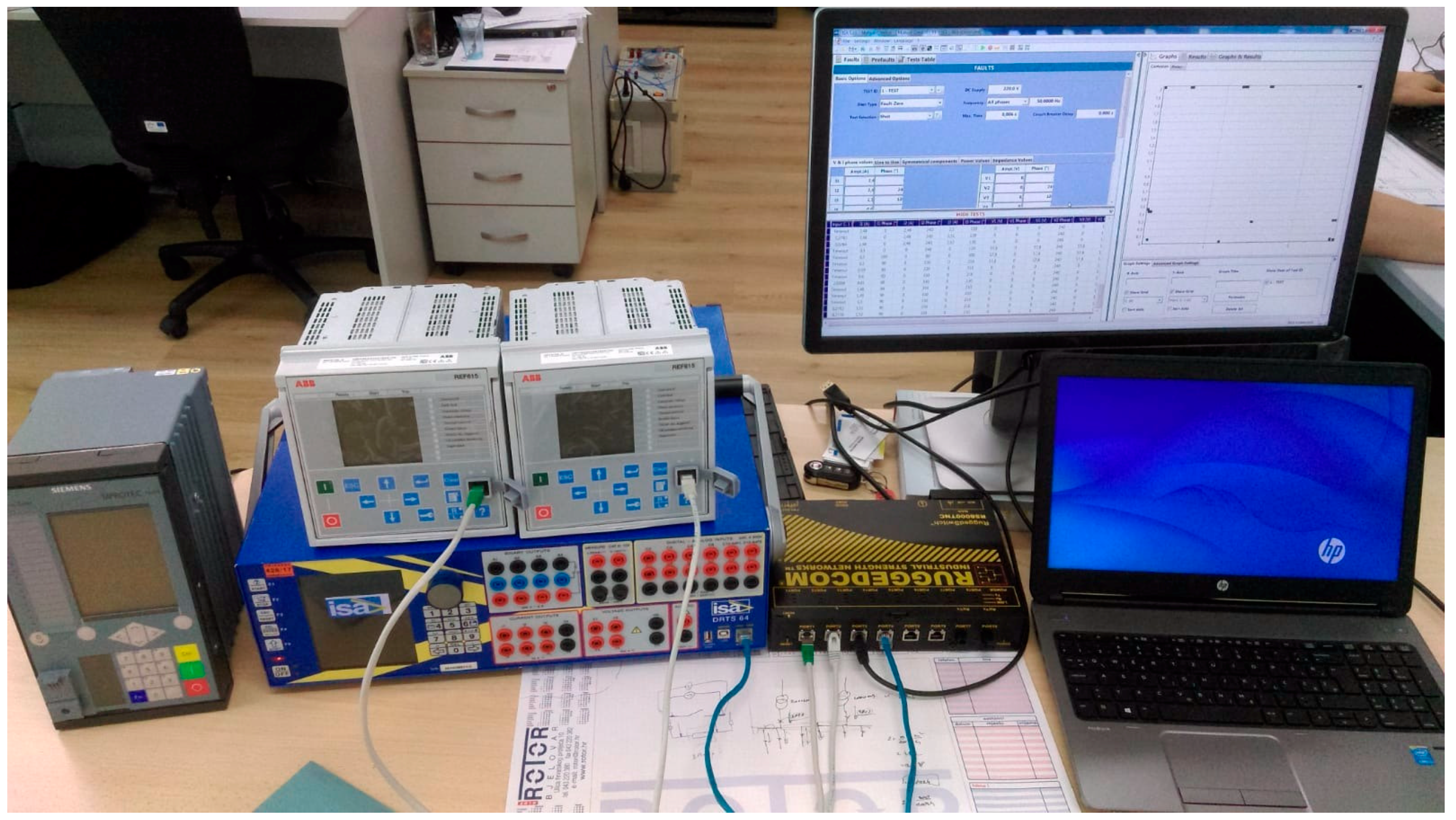
Hardware configuration, shown in
Figure 5, consists of the following elements:
secondary test set (ISA DRTS64) capable of generating customer-defined transient-voltage waveforms and a continued data stream of sampled values [
26];
numerical protection relay (ABB REF615) configured as a merging unit capable of generating continued data stream of sampled values [
27];
numerical protection relay (ABB REF615) configured as a protection relay with protection function operated by measured values or via sampled values;
control PC used for the simulation of transient waveforms according to the IEEE 123-node feeder model; and
communication infrastructure 100BaseFX (RUGGEDCOM RS8000TNC).
To test the performance of the traditional topology, secondary test-set voltage outputs were wired to the protection-relay inputs, and the protection trip contact of the protection relay was wired to the secondary test-set binary dry input. The relay was configured as a traditional protection relay operated with analog voltages, with no relevant data exchange on the communication bus. With the help of the test-set control software, a COMTRADE transient-voltage waveform-generated, according to the MATLAB simulation of the IEEE 123-node feeder model, was simulated and injected into the protection relay. The reaction of the relay was measured with a physical relay trip. Test-set configuration is shown in
Figure 3A. To test the performance of the hybrid topology, it was necessary to incorporate a protection relay capable of receiving sampled values and a merging unit to generate the sampled values based on measured voltages from the secondary test set. The protection relays used in the test bed were customizable, they could be configured to act as classical protection relays, protection relays operated by sampled values, and even to emulate an IEC 61850-9-2LE merging unit. To form a hybrid topology, one of the protection relays was configured as an IEC61850-9-2LE merging unit wired to the secondary test set. The second relay was configured as a protection relay operated by sampled values. The secondary test set generates transient-voltage waveforms and applies them to the physically operated relay, which is working as a merging unit. Reaction of the relay was measured as a GOOSE-message response [
28]. The test-set configuration is shown in
Figure 3B.
In order to test the performance of digital-substation topologies, one of the embedded protection relays was configured to be operated by sampled values, while the secondary test set directly simulated the MATLAB transients to the tested object without the use of an inbetween merging unit. The reaction of the relay was measured as a GOOSE-message response. Test-set configuration is shown in
Figure 3C.
4.3. Test Results
The extended mathematical model of the IEEE 123-node test feeder was used for generating faulty waveforms of voltage and currents. A MATLAB-calculated short-circuit fault was converted to COMTRADE file. The secondary test set was capable of replaying imported transient waveforms as physical currents and voltages or optionally as sampled values according to IEC 61850-9-2LE.
Three different reference fault locations were chosen from the IEEE 123-node test feeder model (nodes 13, 108, 114) to give a statistical overview of the different performances of the substation topologies. These faults represented typical fault currents that a protection relay in node 13 would measure in radial-grid topology. The results of the fault simulation on different substation topologies are shown in
Figure 5. All topologies were tested, with a total of 300 test samples; each fault simulation was performed 100 times for each fault location in groups of three different fault waveforms. It is important to point out that all topologies resulted in a trip signal for all conducted simulations.
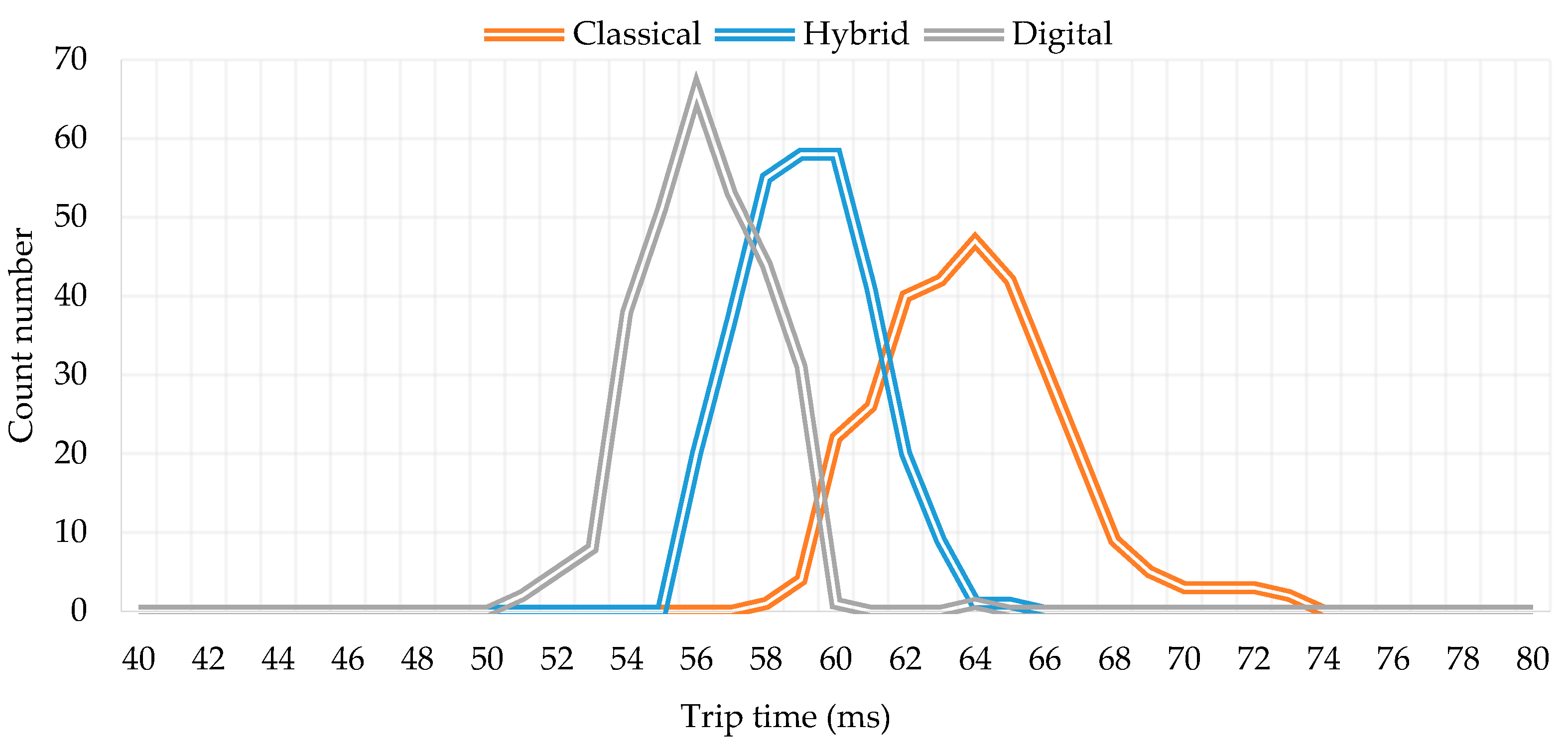
Figure 6 shows the results of a single-phase earth-fault simulation. The statistical distribution of the measured trip signals (for each of the 100 topology simulations) follows the shape resembling a Gauss distribution, with widened standard deviation due to additional delay components. The protection function activated in the relay was a short-circuit function block with a 50 ms trip delay.
By comparing the deviation of the measured trip time to the configured trip time, it is obvious that traditional topology had the lowest average trip time with a median value of 64 ms and tales spanning from 58 ms to 74 ms. Hybrid topology exhibited faster reaction times, with a median value of 59 ms and tales at 55 ms and 66 ms. Fully digital topology had a median at 55 ms for the reaction, while the tales of the result distribution ranged from 50 ms to 60 ms. The delay components responsible for the variation in the signal transmission delay shown in Equation (3) can be adapted for our test model with additional delays.
tp: total time needed to generate and transmit information;
t0: time needed for voltage and current data acquisition and processing;
ta: time needed to save the data to the outgoing buffer of the publisher;
tb: time delay caused by the network communication system;
tc: time needed to save the data to the incoming buffer of the subscriber;
td: time needed to activate/publish the output trip.
For the traditional substation topology, time delays ta, tb and tc do not contribute to the overall delay as the communication bus is not included in the protection system. However, significant delay is added by the activation of the output trip relay. In the hybrid and digital topology, the trip signal is not generated with an output relay, but with a GOOSE message that is significantly faster. By comparing the hybrid and digital topologies, the additional delay in the hybrid topology caused by the implementation of the merging unit causes a 4 ms slower response of the hybrid topology.
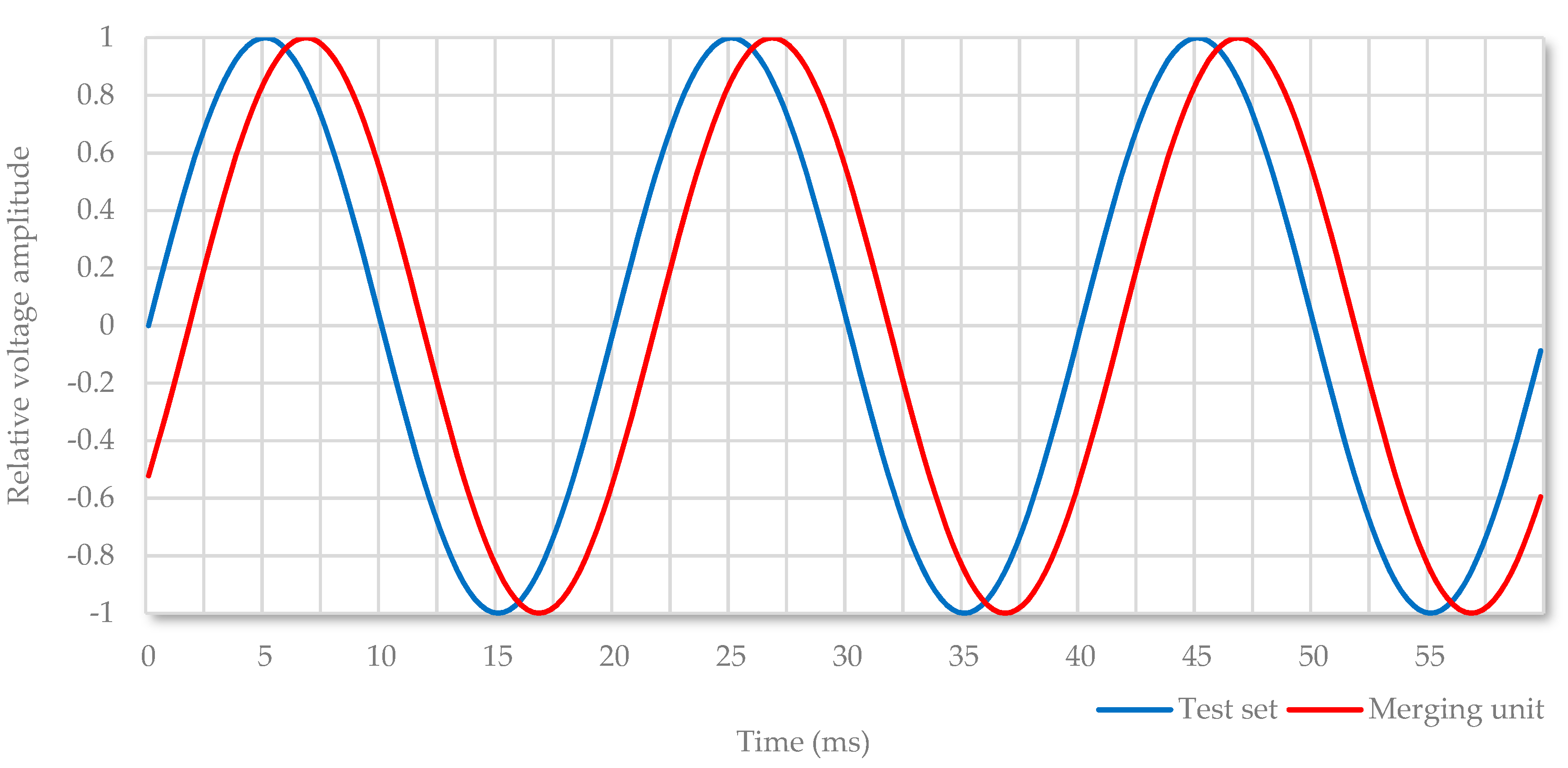
To verify the time delay of sampled values published by the merging unit, a comparison of the sampled values published by the secondary test set and the merging unit was made. Secondary test-set voltage output was wired to the merging-unit input, simultaneously generating analog voltage and a continuous stream of sampled values. The merging unit measured the applied analog voltage and generated its stream of sampled values—4000 samples per second for a 50 Hz system. By comparing the data streams from the merging unit and the secondary test set, a delay of seven samples or 1.75 ms was monitored. The test results are shown in
Figure 6. The shift between signals is a sum result of the time for data acquisition and processing of the analog inputs (
t0), the time needed to save the data to the outgoing buffer of the publisher (
ta), and time delay caused by the network communication system (
tb). The short time delay that is visualized as a phase shift was less than 2.00 ms, which is the maximum acceptable time delay according to the IEC 61869-9 standard for protective and measuring applications [
29].
Although a signal shift of 2.00 ms can have major impact on protection functions that are based on comparative algorithms, such as the differential protection function, time delay in hybrid- or digital-substation topology would not manifest itself as a phase shift as shown in
Figure 7, but rather as a delay on all levels. All analog signals from the process level would be sampled in the same interval, with the delay, thus avoiding signal-time shift [
30].
Network-bandwidth consumption for the single IEC 61850-9-2LE merging units, sending 80 samples per nominal cycle in 50 Hz power system, was 4.4 Mb/s. On a 100 Mb/s network, the theoretical limit of the number of merging units is 22 (97.2 Mb/s), leaving limited resources for the remaining network traffic. A continuing stream of sampled values from merging units affects the switching performance of Ethernet switches, with additional latency introduced due to output-queuing delays. In substation topologies with the number of merging units close to their theoretical limit, it is advised to switch to a 1000 MB/s communication network. However, process-bus networks have shown to be reliable, even at very high network loads. This provides confidence that the process-bus communication infrastructure can meet the requirements of a digital substation [
31]. Furthermore, ease of installation of fully digital compared to traditional substations indicates that a digital-based approach can significantly accelerate the process of distribution-grid digitalization and automation.
4.4. Further Test Scenarios
For an indepth performance analysis of numerical protection relays in the IEC 61850 environment, it is not enough to verify pickup values and trip time. A complete analysis of the protection system, including related communication infrastructure, is needed. The IEC 61850 standard introduces tools and procedures that provide relay-protection specialists with new viewpoints on protection systems, enabling a clear focus on key segments of the protection system instead of procedural tests.
The standard itself does not define testing procedures of complex protection schemes or logical nodes, but rather transparently defines the data structure of protection relays. By introducing the SCL, key information like communication topology, configuration of IEDs, and even setting of protection functions are available to the relay-protection specialist. All data can be used for the development of semiautomated test sequences as shown in
Figure 8. The main station PC can analyze the network topology, simulate, and test protection functions [
32].
Numerical-protection relays in digital substations require a different approach for testing, commissioning, and maintenance. Fully automated testing procedures of protection schemes can be implemented with the introduction of digital substations. However, the IEC 61850 group of standards describes technical requirements in general, leaving a lot of room for manufacturer-dependent interpretation. Key IEC 61850 features, interoperability and interchangeability, are still not fully supported. Current structure of the SCL description files of various manufacturers complies with IEC 61850 standards; however, their implementation resulted in fairly different XML structures, further limiting the development of manufacturer-independent software. Fully automated and adaptive protection-testing software cannot be achieved with the current scope of standards. It is expected that further standardization efforts will strongly focus on interoperability testing, thus enabling the development of more standard-compliant and vendor-neutral implementations.
5. Conclusions
Traditional substation topology is gradually going to be replaced with digital-substation topology in accordance with IEC 61850 standards. A digital-communication bus that covers all substation levels would drastically change the way substations are designed, built, tested, and maintained. A new approach in the way protection systems are tested and maintained, as well as new knowledge, tools, and software for analysis of communication systems may well be needed. Due to the ever-increasing complexity of protection and communication systems, the need for adapted test software arises, which will make use of the potential of SCLs and the transparent manufacturer-independent data structure they contain.
The paper proposes a laboratory test bed for analyzing and comparing the performance of traditional-, hybrid-, and digital-substation topologies. An extended-simulation-environment mathematical model of the IEEE 123-node bus test system was developed, capable of simulating various fault currents and voltage waveforms to test digital representations in sampled values. A laboratory hardware-in-the-loop test bed was proposed with traditional current- and voltage-operated protection relays as well as protection functions operated by sampled values according to IEC 61850-9-2LE. To support the results, many test sequences were performed that could easily be replicated by similar IEC 61850 test beds. Statistical analysis of digital and analog performance supports the conclusions of the paper, demonstrating the usefulness of the proposed test bed in identifying the benefits of process-bus data digitalization.
Differences in standard deviation were recorded for the performed test cases, whereby the results for the digital topology showed the lowest deviation, while the classical topology had the highest deviation. Test cases were based on fault simulations in a mathematical model of the IEEE 123-node bus test system. By comparing fault recordings of the tested protection relays, it is not possible to distinguish waveforms obtained by measured analog values and by sampled values. The interpolated merging unit did not change the accuracy of the protection system, nor did it affect the measured waveforms, as they have the same hardware platform. However, due to different test-set configurations for different substation topologies, trip-signal delays varied, from 55 ms on average for the digital topology up to 64 ms on average for the classical substation topology. The lowest trip signal for the protection relay in the traditional topology was 55 ms due to the additional time delay of the trip coil. Overall signal-transmission performance increased in digital-substation technology, as there were no signal delays besides the Ethernet communication network. Recorded sample-value measurement delays on the communication bus were synchronized via the Precision Time Protocol (PTP) defined by the IEEE 1588 standard, thus avoiding a measured-value phase shift. Protection-function performance in a digital substation is very similar to classical substations, with a signification advantage in terms of information availability.
Author Contributions
G.J. defined and constructed the laboratory-test bed and performed all the simulations. S.S. assisted with the test-bed giving relevant information about the communication standards, different topologies and ideas for future testing. J.H. supervised G.J. as his Ph.D. student, assisted in construction of the laboratory test-bed, analyzed the results and put them into the context of the future smart distribution networks. T.C. participated in the analysis of the results, wrote the paper and defined the main contributions. He is also the corresponding author of the paper.
Acknowledgments
This work was supported in part by the Croatian Environmental Protection and Energy Efficiency Fund under the project Microgrid Positioning (uGRIP) from the ERA Net Smart Grids Plus funding scheme and by the Croatian Science Foundation under the project SUstainable ConCept for integration of distributed Energy Storage Systems—SUCCESS. Facilities for testing were provided by Power System Protection Laboratory, University of Zagreb Faculty of Electrical Engineering and Computing.
Conflicts of Interest
The authors declare no conflict of interest.
References
- Wilson, A.B. Promoting Renewable Energy Sources in the EU after 2020; European Parliamentary Research Service: Aberdeen, UK, 2018. [Google Scholar]
- Pandžić, H.; Kuzle, I.; Capuder, T. Virtual power plant mid-term dispatch optimization. Appl. Energy 2013, 101, 134–141. [Google Scholar] [CrossRef]
- Vasquez, L.O.P.; Meneses, C.A.C.; Martínez, A.P.; Redondo, J.L.; García, M.P.; Hervás, J.D.Á. Optimal Energy Management within a Microgrid: A Comparative Study. Energies 2018, 11, 2167. [Google Scholar] [CrossRef]
- Uribe-Perez, N.; Angulo, I.; Hernandez-Callejo, L.; Arzuaga, T.; de la Vega, D.; Arrinda, A. Study of Unwanted Emissions in the CENELEC-A Band Generated by Distributed Energy Resources and Their Influence over Narrow Band Power Line Communications. Energies 2016, 9, 1007. [Google Scholar] [CrossRef]
- IEC 61850-1—Communication Networks and Systems in Substations, Part 1: Introduction and Overview; International Electrotechnical Commission: Geneva, Switzerland, 2016.
- IEC 61850-9-2—Specific Communication Service Mapping (SCSM)-Sampled Values over ISO/IEC 8802-3; International Electrotechnical Commission: Geneva, Switzerland, 2011.
- UCA International Users Group. Implementation Guideline for Digital Interface to Instrument Transformers Using IEC 61850-9-2; UCA International Users Group: Paris, France, 2004. [Google Scholar]
- Sučić, S.; Dragičević, T.; Havelka, J. A device-level service-oriented middleware platform for self-manageable DC microgrid applications utilizing semantic-enabled distributed energy resources. Int. J. Electr. Power Energy Syst. 2014, 54, 576–588. [Google Scholar] [CrossRef]
- Sučić, S.; Dragičević, T.; Capuder, T.; Delimar, M. Economic dispatch of virtual power plants in an event-driven service-oriented framework using standards-based communications. Electr. Power Syst. Res. 2011, 81, 2108–2119. [Google Scholar] [CrossRef]
- Mackiewicz, R. Benefits of IEC 61850 Networking; UCA International Users Group: Paris, France, 2004. [Google Scholar]
- Ángel, S.; Aleix, S.; Ramon, M.P.; Agustín, Z. Using IEC 61850 GOOSE Service for Adaptive ANSI 67/67N Protection in Ring Main Systems with Distributed Energy Resources. Energies 2017, 10, 1685. [Google Scholar]
- Andersson, L.; Brunner, C.; Engler, F. Substation Automation based on IEC 61850 with new process-close Technologies. In Proceedings of the 2003 IEEE Bologna Power Tech Conference Proceedings, Bologna, Italy, 23–26 June 2003. [Google Scholar]
- Adewole, A.C.; Tzoneva, R. Impact of IEC 61850-9-2 Standard-Based Process Bus on the Operating Performance of Protection IEDS: Comparative Study. In Proceedings of the 19th World Congress the International Federation of Automatic Control, Cape Town, South Africa, 24–29 August 2014. [Google Scholar]
- IEC 61850-10—Communication Networks and Systems in Substations, Part 10: Conformance Testing; International Electrotechnical Commission: Geneva, Switzerland, 2012.
- Schossig, T. Testing in Substations with IEC 61850-Advanced topics and extended possibilities. In Proceedings of the 10th IET International Conference on Developments in Power System Protection IEEE, Edinburgh, Scotland, 29 March–1 April 2010. [Google Scholar]
- Atienza, E. Testing and Troubleshooting IEC 61850 GOOSE-Based Control and Protection Schemes. In Proceedings of the IEEE 63rd Annual Conference for Protective Relay Engineers, College Station, TX, USA, 29 March–1 April 2010. [Google Scholar]
- Rafaela, C.; Luis, C.; Carlos, F.; Rui, F.; Fernando, L. Protection, Automation and Control Systems and the IEC 61850 Paradigm—New Testing and Maintenance Challenges. In Proceedings of the 2016 51st International Universities Power Engineering Conference, Coimbra, Portugal, 6–9 September 2016. [Google Scholar]
- Singh, V.K.; Thoke, A.S.; Awasthi, C.P. Procedures for testing control and protection scheme based on GOOSE messages-methodology and constraints from engineering perspective. In Proceedings of the 1st IEEE International Conference on Power Electronics, Intelligent Control and Energy Systems (ICPEICES-2016), New Delhi, India, 4–6 July 2016. [Google Scholar]
- IEC 61850-9-2—Configuration Description Language for Communication in Electrical Substations Related to IEDs; International Electrotechnical Commission: Geneva, Switzerland, 2011.
- Shin, I.J.; Song, B.K.; Eom, D.S. Auto-Mapping and Configuration Method of IEC 61850 Information Model Based on OPC UA. Energies 2016, 9, 901. [Google Scholar] [CrossRef]
- Kersting, W.H.; Shirek, G. Short Circuit Analysis of IEEE Test Feeders. In Proceedings of the 2012 IEEE/PES Transmission & Distribution Conference and Exposition, Montevideo, Uruguay, 3–5 September 2012. [Google Scholar]
- Pena, I.; Martinez-Anido, C.B.; Hodge, B.M. An Extended IEEE 118-Bus Test System with High Renewable Penetration. IEEE Trans. Power Syst. 2017, 1, 281–289. [Google Scholar] [CrossRef]
- Schneider, K.P.; Mather, B.A.; Pal, B.C.; Ten, C.W.; Shirek, G.J.; Zhu, H.; Fuller, J.C.; Pereira, J.L.R.; Ocnoa, L.F.; Araujo, L.R. Analytic Considerations and Design Basis for the IEEE Distribution Test Feeders. IEEE Trans. Power Syst. 2018, 3, 3181–3188. [Google Scholar] [CrossRef]
- Skendzic, V.; Ender, I.; Zweigle, G. IEC 61850-9-2 Process Bus and Its Impact on Power System Protection and Control Reliability; Schweitzer Engineering Laboratories: Pullman, DC, USA, 2007. [Google Scholar]
- Eidson, J.; Lee, K. IEEE 1588—Standard for a Precision Clock Synchronization Protocol for Networked Measurement and Control Systems. In Proceedings of the 2nd ISA/IEEE Sensors for Industry Conference, Houston, TX, USA, 19–21 November 2002. [Google Scholar]
- ABB REF 615 Manual “615 Series Technical Manual-ABB Group”; ABB: Vaasa, Finland, 2010.
- ISA TDMS Manual “Test Data Management Software”; ISA: Tiano, Italy, 2011.
- Wannous, K.; Toman, P. Sharing sampled values between two protection relays according to standard IEC 61850-9-2LE. In Proceedings of the 19th International Scientific Conference on Electric Power Engineering, Brno, Czech Republic, 16–18 May 2018. [Google Scholar]
- IEC 61869-9:2016—Digital Interface for Instrument Transformers; International Electrotechnical Commission: Geneva, Switzerland, 2016.
- Strnad, I.; Pregrad, G.; Višić, I.; Gazivoda, S. Development and Implementation of the Smart Measuring Unit with MU and PMU Functionalities for Smart Grid Applications. In Proceedings of the First International Colloquium on Smart Grid Metrology, Split, Croatia, 24–27 April 2018. [Google Scholar]
- Ingram, D.; Schaub, P.; Taylor, R.R.; Campbell, D.A. Performance Analysis of IEC 61850 Sampled Value Process Bus Networks. IEEE Trans. Ind. Inform. 2013, 9, 1445–1454. [Google Scholar] [CrossRef]
- Burkart, D.; Edwards, W.; Atalay, A.; Snuggs, S. If you cannot test it, you cannot use it—IEC 61850 GOOSE system designed with testing in mind. In Proceedings of the 2017 70th Annual Conference for Protective Relay Engineers, College Station, TX, USA, 3–6 April 2017. [Google Scholar]
© 2018 by the authors. Licensee MDPI, Basel, Switzerland. This article is an open access article distributed under the terms and conditions of the Creative Commons Attribution (CC BY) license (http://creativecommons.org/licenses/by/4.0/).


