Environmentally Friendly Compact Air-Insulated High-Voltage Substations


1
School of Engineering, Cardiff University, Cardiff CF24 3AA, UK
2
Electrical Engineering Department, Khalifa University of Science and Technology, Abu Dhabi 2533, UAE
3
National Grid, Warwick CV34 6DA, UK
*
Author to whom correspondence should be addressed.
Energies 2018, 11(9), 2492; https://doi.org/10.3390/en11092492
Submission received: 23 August 2018
/
Revised: 13 September 2018
/
Accepted: 16 September 2018
/
Published: 19 September 2018
(This article belongs to the Special Issue 10 Years Energies - Horizon 2028)
Abstract
:This paper investigates the possible options for achieving a substantial reduction in a substation footprint using air-insulated switchgear as a more environmentally-friendly alternative to gas-insulated substations that use SF6 gas. Adopting a new approach to surge arrester location and numbers, International Electrotechnical Commission (IEC) minimum clearances can be successfully selected instead of the maximum clearances as currently adopted by many utilities, as is the case in the UK. In addition, innovative alternative compact busbar arrangements using vertical and delta configurations have been proposed by the authors. A further opportunity for compaction is offered by the application of compact and integrated technology offered from several manufacturers. The full overvoltage control within the entire substation under any surge condition is a key aspect of the feasibility of this type of substation. This work demonstrates that the new design option can be an attractive alternative for future substation configuration with minimum footprint.
1. Introduction
Increasing the integration of renewable sources into the grid requires the reinforcement of power networks, and the construction of new lines and substations [1]. Restriction on land availability could suggest a wider application of gas-insulated substations (GIS) in future. However, despite the very efficient GIS space reduction, strong environmental pressures make this option less attractive due to the greenhouse effect of the insulating gas SF6 [2,3,4,5]. A sufficiently compact air-insulated substation would offer a cost-effective solution in many cases where restrictions in available land are encountered. For example, compaction could be successfully adopted for the construction of extension bays within existing substation boundaries. In many cases of substation replacement, the safety and operational issues associated with bay-by-bay replacement impose the selection of a GIS solution. However, with a compact design, a replacement substation could be constructed off-line on land of a reduced footprint that is adjacent to the existing substation, without affecting its availability during the construction period.
The substation footprint is not only affected by the minimum clearances, but also by the overall design of the substation, which determines the required ground surface and volume that is occupied by the plant. Typical substation layout arrangements are: single bus, double breaker, multi-section double bus, and double bus, in addition to mesh configurations. The layout arrangement is usually selected to obtain the desired level of security of supply. The number of buses, circuit breakers, and disconnectors are a function of the selected layout, and consequently, the substation footprint. Furthermore, a significant area is required for the installation of instrument transformers. Conventional high-voltage current and voltage transformers require separate equipment and clearances between them. Recent technologies offer similar or better performance using integrated equipment.
This paper describes the combination of a number of existing and new compact solutions, IEC 60,071 minimum clearances [6,7], innovative busbar arrangements, and non-conventional equipment, which allow for the achievement of a substantial reduction of the substation footprint using air-insulated switchgears. All these solutions satisfy the safety requirements as described in current UK standards related to the substations [8,9].
An important evaluation for the adoption of minimum clearances is the performance of the compact substation under lightning and switching surge conditions. When significant reductions of air clearances between phases and the shortening of switch bay lengths are achieved, increased surge reflections and phase-to-phase couplings are expected. The effect of the installed High-Voltage (HV) equipment within the substation needs also to be taken into account in order to estimate their influence on surge voltage magnitudes at different locations within the substation. All of these factors can lead to a different surge response of the substation. To quantify the surge voltages, an air insulated compact substation model is developed using the Electro Magnetic Transient Program (EMTP) in order to assess the impact of compaction within the substation. An evaluation of the potential footprint reduction is then performed, assuming a single line entrance bay as a case study for the comparison between conventional layout and compact configuration, which introduces the proposed compact solutions.
The lightning surge performances of existing and compact substations were computed following a shielding failure on an incoming line. This is then followed by a switching surge investigation to evaluate the performances of the two substation designs under switching operations. Two switching operations were selected: a breaker closure after fault clearance, and the energization of an incoming line; the effect of high-speed re-closure and circuit-breaker pole scatter are also taken into account in the statistical studies. The benefits of an extended use of surge arresters within the substation are also explored. In this paper, how to reduce air clearances with overvoltage control (Section 2), and then how to gain further compaction in adopting innovative alternative compact busbar arrangements (Section 3) are discussed. A further step is the introduction of selected plant technologies (Section 4). All of these compaction proposals have been introduced as example on the substation bay (Section 5).
2. Reduced Air Clearances with Overvoltage Control
The planning and the design of the super-grid system in England and Wales at 400 kV began in the 1960s [10]. The conductor clearances were established when overvoltage control was limited and the system was not subjected to environmental pressure. This led to the introduction of significant safety margins for minimum clearances in UK and international standards.
Figure 1 shows the evolution of minimum clearance distances for 400 kV and 275 kV systems in the UK since the 1960s. The original design was changed twice in order to avoid the effect of long wave-front switching surges, and to take into account additional electrical and civil tolerances. In the 1970s, the minimum phase-to-earth distance was set to 3 m, and the phase-to-phase clearance was set to 3.6 m. The green dotted line shows the targeted proposed compaction change from the current minimum clearances to the minimum proposed in IEC 60,071 values (Figure 1). The last change set the phase-to-earth and phase-to-phase distances to the current values [9], as shown in Table 1.
IEC 60071 [6,7] suggests three levels of switching impulse withstand voltage (SIWV) for 420 kV systems, equal to 850,950, and 1050 kV (peak value). The associated lightning impulse withstand voltage (LIWV) is between 1050 and 1425 kV (peak value). The clearance values are then correlated by the selected LIWV and SIWV values, as described in Annex A of IEC 60071-2 [7]. It is important to note that these minimum clearances are determined with a conservative approach and by considering common electrode configurations. Within the standard specification, it is clarified that it is possible to adopt lower clearances in case of more favorable gap configuration or lower prospective overvoltage levels.
In fact, the dielectric strength of the air insulation is a function of many factors, such as the geometric configuration of the electrodes, atmospheric conditions, and the shape of the applied surge. The geometric configuration of the electrodes influences the electric field distribution. In particular, it is shown that the rod-plane configuration results in a minimum value for the breakdown voltage under positive impulse compared with other electrode configurations, and its flashover voltage increases linearly with electrode distance. Therefore, the rod-plane was selected as the reference for electrode configuration. The data available on the breakdown voltage for a rod-plane gap represents a useful indication for the determination of safety distances, but it may determine a conservative safety margin. In substations, actual air clearances show important differences from this reference value, mainly because of the presence of electrodes of different shapes. In high-voltage substations, the air gap configurations that present a gap factor lower than 1.5 are very rare. If a rod shape is present, it is possible to adopt a gap factor of 1.15, by introducing shielding rings on the rod [11]. Since it is a very difficult task to consider all possible geometries of HV equipment, IEC standards take into account more common configurations. For phase-to-ground clearances, the rod-structure and conductor-structure configurations are considered. For phase-to-phase clearances, the rod-conductor and conductor-conductor parallel configurations are used. Recently, a new National Grid (NG) safety document has been proposed defining minimum clearances taking into account the type of geometry as a reference to the IEC values [8].
The electrical characteristics of a surge such as the magnitude, shape, duration, and polarity of the applied surge are all important factors affecting the dielectric strength of air. In addition, the presence of insulators on a complex structure can affect the withstand level and, therefore, it needs to be taken into account. Jones and Waters [12] highlighted useful observations and findings related to the effect of the insulator on withstanding switching and lightning impulses.
Therefore, it is not an easy task to reduce the conservative margin for these two factors. However, the highest LIWV and SIWV values presented in IEC 60071 are similar to current practice in the UK. With the adoption of a reliable overvoltage protection, e.g., ZnO surge arresters, any incoming surge could be safely limited and kept within the limits of the system withstand and protection margins. This additional protection permits the selection of smaller withstand values, as shown in Table 1. Phase-to-phase and phase-to-ground clearances are reduced in comparison with conventional substation designs, as currently adopted. Several techniques can be adopted to control surge magnitudes due to switching operations such as pre-insertion resistors, controlled switching using point-of-wave techniques, and surge arresters with high-energy absorption capability.
3. Innovative Alternative Compact Busbar Arrangements
The current arrangement generally adopted for high-voltage substations is the horizontal configuration. This arrangement offers a geometrical configuration that is easy to build, safer to access for maintenance, and it allows for the standardization of support structures. However, the footprint of the horizontal arrangement requires significant land area, and in a new site, this can be a very demanding constraint to satisfy [13].
In this work, new alternative configurations are proposed with the adoption of minimum standard clearances and alternative physical arrangements. These proposals will allow a significant reduction in a busbar footprint. Figure 2 shows a vertical section of the horizontal busbar, and Table 2 shows a detailed comparison of horizontal busbar arrangements using the clearances currently adopted in UK and the proposed equivalent compact configuration. It is important to note that the bay width is reduced by 40% using the compact solution. For comparison, the dimensions of a 400 kV Gas Insulated Substation (GIS) bay are also shown in Table 2.
It is important to note that the width of the GIS bay is significantly smaller, at around 7.0 m. However, if the bay is connected to an incoming overhead line, it will still require a gantry, surge arresters, and voltage instrument transformers. Such a connection requirement will need an area of 17.5 m × 10 m in addition to the GIS area, and this needs to be accounted for when estimating the footprint reduction.
Two new non-horizontal busbar arrangements are proposed for compaction: the delta and vertical arrangements, as shown in Figure 3a,b. The computed electrical potential around the conductors on a vertical section are shown in Figure 3c,d respectively. The delta arrangement could be useful when applied to the switchgear bays; while the vertical busbar arrangement could be readily extended to a double busbar layout using the same supporting structures, if polymeric cross-arms are utilized. These were initially investigated in [14,15,16] and have further studied in details in this work.
Figure 4 shows the coordinates of the busbar centers for the proposed arrangements using IEC 60,071 minimum clearances. The physical width of the system is only 1.14 m. It is worth noting that the centers of the three axes of the vertical busbar arrangement are not vertically aligned. This will avoid possible problems related to conductive paths being formed under heavy rain.
The proposed vertical arrangement uses two insulators for each busbar. Under short circuit forces, a single insulator configuration could not offer enough mechanical strength to support the busbars. Therefore, an extra insulator is suggested to enhance the mechanical strength of the proposed busbar arrangement. Detailed mechanical assessment is needed to verify this, in order to reduce the number of vertical supports, a maximum distance between them should be adopted. Further detailed mechanical/structure-based investigations are required to establish the optimal position and number of insulators.
If there is a need to reduce the maximum height of the busbars, a cage on both sides of the busbar may be considered. This action allows for the reduction of the busbar height to a maximum of 10.4 m, which is significantly below the recommended maximum 12.5 m height for new substations in the UK. In this case, the earth screen can be fitted with access gates or fitted as removable panels for maintenance work.
Table 3 shows the bay width and its height for a substation bay adopting existing designs and for the proposed compact configurations. From the table, the significant footprint reduction achievable is clearly demonstrated.
4. Selected Plant Technologies for Further Compaction
The research on a high-voltage plant with several integrated functions and the application of non-conventional instrument transformers is under active development by manufacturers. Selected applicable examples of innovative compact equipment are short-listed and described in this section:
- (i)
- Integrated arrester: systems are described in [17]. In particular, the metal oxide surge arresters have been used as post insulators in a 420 kV substation. This solution offers not only compaction in new substations, but it also introduces overvoltage protection when retrofitting substations that were not designed to accommodate surge arresters.
Another interesting example of integrated design is a transformer fitted with integrated surge arresters, where arresters are installed close the transformer bushings. In addition to providing a compact arrangement, this solution offers a better overvoltage protective performance due to the short distance between the surge arrester and the transformer. Additional cost saving is also possible through a reduced number of foundations. The adoption of surge arresters mounted on a super grid transformer (SGT) allows a footprint reduction equal to the length of the equipment and inter-equipment clearances along the bay length. Therefore, there is at least a 7-m reduction in length for a typical 400 kV substation bay.
- (ii)
- Traditionally, circuit breakers require more frequent maintenance than any other HV substation equipment. To provide access for maintenance or repair, isolators or disconnectors are installed on each side of the circuit breaker. However, the failure and maintenance rate of SF6 disconnecting circuit breakers are significantly lower compared with older technologies [18], requiring de-energization in the order of 15-year intervals; hence, maintenance is not as critical. An alternative device is a disconnecting circuit breaker (DCB), which is a combination of a disconnector and a circuit breaker, where the disconnector is contained within the SF6 chamber. This device fulfils all the requirements for a circuit-breaker, as well as those for a disconnector. In particular, normal isolation functions of lines for transformers can be fulfilled by DCBs. In order to offer the equivalent safety level of working conditions as in conventional devices, a locking system and earth switch are integrated. The outage duration of DCBs is significantly lower than that of the combination of conventional installation of circuit breakers and disconnectors, thereby reducing the substation operational costs.
- (iii)
- Conventional high-voltage instrument transformers occupy large areas within the substation. Therefore, a significant reduction in substation footprint may not be realizable using conventional wound currents (CTs) and voltage transformers (VTs). Non-conventional instrument transformers and fiber-optic transducers offer opportunities for advantageous applications in HV substations due to their small size and weight. These non-conventional devices can be installed and integrated with the designs of circuit breakers and bushings, to achieve considerable savings in switchgear bay footprints, and in particular, the shortening of bay lengths. This technology has already been introduced in substations of up to 550 kV. Non-conventional technologies offer significant benefits in measurement performance, and they present no risk of fire explosion compared with equipment filled with oil. Further benefits of passive optical sensors are high immunity to electro-magnetic interference and electrical isolation between the sensor head located at the high-voltage conductor and the ground [19]. In addition, no greenhouse effect is introduced since optical fiber transducers are also SF6 free.
The combination of the two new designs of the disconnecting circuit breaker and the optical current sensor is now available for voltages up to 550 kV. One of the manufacturers indicates that a 50% footprint reduction is feasible in comparison with a conventional solution, which includes disconnecting and current transformer equipment [20,21]. Another important feature of these new devices is the requirement of digital control. In the past, this requirement was a disadvantage since it was at an additional cost in comparison with the conventional solution. However, the future transmission networks will have a wider and more precise control of network state, which is pushing towards an increased adoption of smart grid solutions (IEC 61850-9-2LE bus) [22]. This “compact” technology is designed to fulfil this requirement as it is “smart grid ready”.
The application of this new equipment to part of the bay offers a significant reduction of the bay length.
5. Application of Compaction Options to a Substation Bay
The footprint of an air-insulated substation is dependent on its layout (e.g., double busbar) and the number of connected overhead lines to the substation. In order to simplify the comparison between the conventional and the compact footprint, the analysis has focused on the area required by a single 400 kV switch bay, including a double busbar section. A study is carried out to estimate the space saving that can be theoretically achieved with some of the illustrated compact solutions listed above, the introduction of IEC minimum clearances, innovative busbar arrangements, and novel equipment.
The conventional substation layout and its footprint are used as reference for the calculations. A typical line-entry bay configuration is shown in Figure 5 and Table 4. The total length from the gantry to the reserve busbar is 72 m. A number of compaction scenarios were investigated, and a proposed layout is suggested, as shown in Figure 6. This is achieved using IEC minimum clearances, the installation of surge arresters (SA) suspended on the gantry, and the adoption of an integrated disconnecting circuit breaker (CB-DS) with fiber-optic current sensor. These adoptions permit a significant footprint saving, since it takes advantage of eliminating several equipment lengths and their relative longitudinal clearances, as shown in Figure 6. The longitudinal part of the entry bay adopts the delta busbar configuration. The vertical busbar is selected for the main and the reserve busbars (BB) as main connection between each line entrance.
The bay length reduction is almost 48% for this layout and 73% in the footprint reduction, as shown in Table 5. The width of such compact bay still includes the clearance distance on both sides that allow maintenance and access between contiguous bays.
6. Performance of the Compact Design under Surge Conditions and Overvoltage Protection
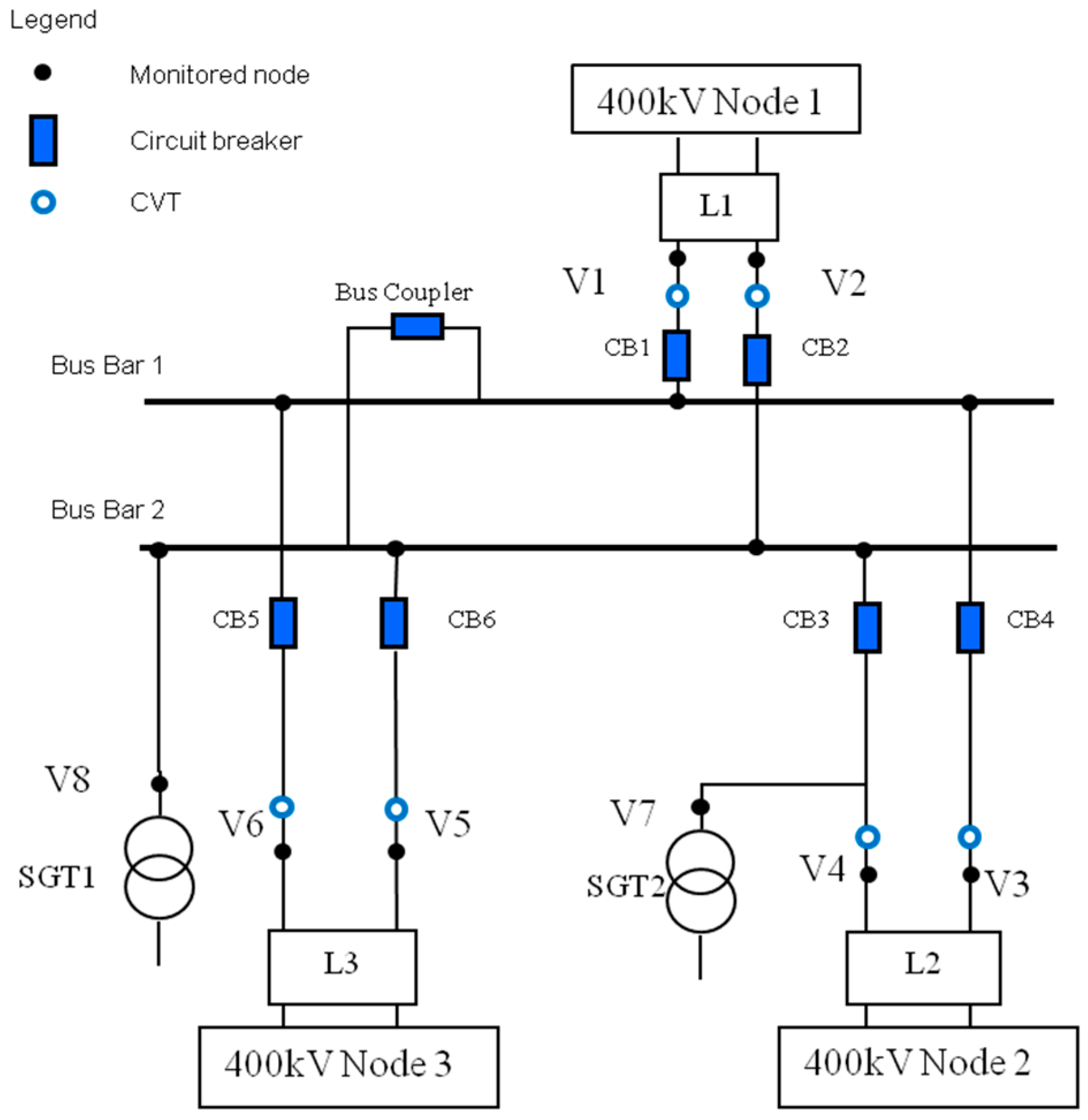
One of the key aspects of the proposed substation compaction is the achievement of a full overvoltage control at all substation locations and for all surge scenarios. Therefore, the lightning and switching overvoltages were computed for a compact substation model. These results were then compared with those obtained for an existing conventional substation layout. The example shown in Figure 7 of a single line diagram of the double busbar layout with three incoming overhead lines and two feeding connections via super grid transformers is used in this case. The model parameters were obtained from industrial equipment sources.
For the main and reserve busbars in the compact layout, the proposed vertical symmetrical arrangement is adopted (Figure 4b). In the conventional layout model, the two centers of the main busbar are 20 m apart, while in the compact layout, there is only a 4.5 m distance between the closest phase conductors.
The overvoltages within the substation were computed at eight nodes: V1 and V2 at the line entrance of Line L1, V3 and V4 at the line L2 entrance, V5 and V6 at the line L3 entrance, and V7 and V8 at the primary sides of SGT2 and SGT1, as shown in Figure 7.
6.1. Lightning Surges
In this investigation, lightning surge simulations were performed to evaluate the maximum overvoltages within the substation following a direct strike on a phase conductor. The stroke is injected at 1.5 km from the substation directly to one of the phase conductors, and the lightning source is modelled as a 32 kA current source, using a positive Heidler surge function, with a front duration 1.2 µs and 50 µs tail time, and with a parallel resistance of 400 Ω as the lightning path impedance [22,23]. It is worth noting that the selected current magnitude is one of the highest possible values for direct strike occurrences and, consequently, it will generate the highest overvoltages. Higher lightning current magnitudes will be intercepted by the earth-wire, which can then cause a back-flashover event.
- (i).
- Without any surge arrester protection, the maximum surge magnitudes for both configurations are well above 5 pu, exceeding the existing and compact withstanding levels of 4.16 pu and 3.06 pu, respectively. The pu base voltage is set as the peak of the maximum operational continuous rms voltage of 420 kV. Similar lightning simulations with the injection point on the other two transmission lines showed similar results.
- (ii).
- A second set of simulations were carried out placing surge arresters at the SGT terminals. As expected, the overvoltage magnitudes were reduced but they were not sufficient to protect the entire site. The computed overvoltages are 1546 kV (4.5 pu) and 1496 kV (4.4 pu) for the existing and conventional substations, respectively.
- (iii).
- A third simulation assumed a wider use of surge arresters. In addition to the surge arresters at the SGT terminals, additional surge arresters were placed at the line entrances and at the busbar coupler. The results showed a surge range between 2.4 to 3.0 pu and 2.4 to 2.7 pu for conventional and compact substations respectively, as shown in Table 6.
This arrangement reduces any lightning overvoltage incoming into the substation to levels below the LIWL for both designs. The lightning impulse protection margin (LIPM), calculated as percentage difference between the LIWL and the lightning residual voltage (LIRV) is also shown in Table 6, where the minimum margin is 12%. It is worth recalling that the surge arrester model was selected according to the specifications defined by National Grid [24].
6.2. Switching Surges
A further overvoltage simulation has focused on the computation of maximum voltages under switching conditions [25,26,27,28,29]. The selected operation regime for this investigation assumes that only one circuit of each line is connected to the main busbar, while the remaining circuits are connected to the reserve busbar. This regime is usually selected as the higher level of continuity of service, since it reduces the consequences of a fault on a section of the busbar.
In [30], the authors suggest line closure after a fault and line energization as typical events that initiate onerous switching overvoltages; therefore, two scenarios were considered:
- (i).
- Scenario A: a closing operation at the substation entry point (L1), where the substation feeds from Line 1 (L1), and:
- (ii).
- Scenario B: energization of a long line (L1), with the substation connected to the 400 kV network from the remaining Lines (L2 and L3).
The overvoltage magnitude is significantly affected by the circuit-breaker pole scatter and by the presence of trapped charge during re-closure operations. This parameter has been evaluated using a systematic-switch approach. The EMTP software has been set to perform 1000 switching operations using the combination of all three pole-steps over 120 degrees. The trapped charge on the line is also modelled by introducing a special current source that is connected to the isolated line [31,32].
Both scenarios (A and B) were simulated without and with the trapped charge (TP); the effect of corona losses during the propagation of the overvoltage along the transmission line is neglected. This assumption is conservative because a reduction of the peak of lightning by corona losses is possible [33]. Then, the peak voltage reduction was calculated with the application of surge arresters at all line entries, at transformer terminals and at the bus-coupler, the results of which can be seen in Table 7.
The simulations results show that the maximum overvoltage, following a closing operation, is below the SIWL for both conventional and compact designs, despite the lower margin for the compact substation (Scenario A). If a trapped charge is present (scenario A-TP), equipment failure may happen since the overvoltages are exceeding the SIWL for the two layouts. The switching impulse protection margin (SIPM) is calculated as the percentage difference between the SIWL and the switching residual voltage (SIRV). With the wide application of overvoltage protection (scenario A-SA), the SIMP is at least 5% and 12% for the conventional and the substation, respectively.
From the above results, it is clearly demonstrated that the overvoltages can be controlled to be within the SIWV for both layouts using metal-oxide surge arresters. Increased margins of protection could also be achieved using controlled switching (point-on-wave) or other techniques (e.g., pre-insertion resistors).
7. Conclusions
The dielectric properties of SF6 gas allow for the design of a very compact electrical substation. However, its negative impact on the environment is now becoming an issue. This paper proposes more environmentally friendly compact air-insulated substations that are up to 70% smaller in footprint compared to the existing designs.
The results demonstrate the satisfactory performance of compact substations under lightning and switching overvoltages. The extended use of surge arresters and a new approach to their locations within the substation plays a fundamental role in the extent of these performances.
The application of combinations of compact solutions to a standard 400 kV switch bay is shown to offer significant reduction in occupied ground area. Furthermore, new technologies offer significant benefits in the voltage and current measurements, with no risk of catastrophic failure compared with equipment filled with oil.
Author Contributions
Conceptualization, A.M.H., H.G. and P.C.; Investigation, M.A.; Writing—original draft, M.A.; Writing—review & editing, M.A. and A.M.H.
Funding
This research received no external funding.
Conflicts of Interest
The authors declare no conflict of interest.
References
- Schaber, K.; Steinke, F.; Mühlich, P.; Hamacher, T. Parametric study of variable renewable energy integration in Europe: Advantages and costs of transmission grid extensions. Energy Policy 2012, 42, 498–508. [Google Scholar] [CrossRef] [Green Version]
- Preve, C.; Piccoz, D.; Maladen, R. Validation methods of SF6 alternative gas. In Proceedings of the 23rd Conference and Exhibition on Electricity Distribution (CIRED), Lyon, France, 15–18 June 2015; p. 493. [Google Scholar]
- Zhou, S.; Teng, F.; Tong, Q. Mitigating Sulfur Hexafluoride (SF6) Emission from Electrical Equipment in China. Sustainability 2018, 10, 2402. [Google Scholar] [CrossRef]
- Beroual, A.; Haddad, A. Recent Advances in the Quest for a New Insulation Gas with a Low Impact on the Environment to Replace Sulfur Hexafluoride (SF6) Gas in High-Voltage Power Network Applications. Energies 2017, 10, 1216. [Google Scholar] [CrossRef]
- Widger, P.; Haddad, A.M. Evaluation of SF6 Leakage from Gas Insulated Equipment on Electricity Networks in Great Britain. Energies 2018, 11, 2037. [Google Scholar] [CrossRef]
- IEC 60071-1. Insulation Co-Ordination—Part 1: Definitions, Principles and Rules; IEC Standards, Ed.8; IEC: Geneva, Switzerland, 2006. [Google Scholar]
- IEC 60071-2. Insulation Co-Ordination—Part 2 Application Guide; IEC Standards, Ed.; IEC: Geneva, Switzerland, 1996. [Google Scholar]
- National Grid Technical Specification, Substations, TS 2.01 Part 1—Issue 1; National Grid: London, UK, October 2014.
- National Grid UK. Relevant Electrical Standards; NGET; National Grid: London, UK, 9 January 2006. [Google Scholar]
- Davenport, W.M.W. Requirements and Specification of 400 kV Substations for C.E.G.B. Presented at the Design Criteria and Equipment for Transmission at 400 kV and Higher Voltages, London, UK, 27 September–1 October 1965; pp. 128–131. [Google Scholar]
- Paris, L.; Taschini, A.; Schneider, K.H.; Weck, K.H. Phase-to-ground and phase-to-phase air clearances in substations. ELECTRA 1973, 29, 29–44. [Google Scholar]
- Jones, B.; Waters, R.T. Air insulation at large spacings. Proc. IEE 1978, 125, 1152–1176. [Google Scholar] [CrossRef]
- Ullah, N.; Haddad, A.; German, D.M.; Tong, Y.K. Insulation coordination of compact substations. Presented at the 28th International Universities Power Engineering Conference (UPEC), Thessaloniki, Greece, 1–3 September 2003; pp. 105–108. [Google Scholar]
- Albano, M.; Haddad, A.; Griffiths, H.; Coventry, P. Performance of Compact Air Insulated Substations under Surge Conditions. In Proceedings of the ISH2011, Hannover, Germany, 22–26 August 2011. [Google Scholar]
- Albano, M.; Haddad, A.; Griffiths, H.; Coventry, P. Electric and magnetic fields in 400kV compact Substations. In Proceedings of the International Symposium on High Voltage Engineering—ISH 2009, Cape Town, South Africa, 24–28 August 2009. [Google Scholar]
- Albano, M.; Haddad, A.; Griffiths, H.; Coventry, P. Air insulated compact Substations. In Proceedings of the 43rd International Universities Power Engineering Conference—UPEC 2008, Padova, Italy, 1–4 September 2008; ISBN 978-88-89884-09-6. [Google Scholar]
- CIGRE Working Group A3.17. MO Surge Arresters Stresses and Test Procedures; Technical Brochures 544; CIGRE: Paris, France, August 2013. [Google Scholar]
- Andersson, P.-O.; Olovsson, H.-E.; Franzén, B.; Lager, U.; Lundquist, J. Applications of Disconnecting Circuit-Breakers; Report A3-201; Cigré Session: Paris, France, 2004. [Google Scholar]
- Rahmatian, F. High-voltage current and voltage sensors for a smarter transmission grid and their use in live-line testing and calibration. In Proceedings of the 2011 IEEE Power and Energy Society General Meeting, Detroit, MI, USA, 24–29 July 2011; pp. 1–3. [Google Scholar]
- Bohnert, K.; Gabus, P.; Brändle, H. Fiber-Optic Current and Voltage Sensors for high-Voltage Substations. In Proceedings of the 16th International Conference on Optical Fiber Sensors, Nara, Japan, 14–17 October 2003; pp. 752–754. [Google Scholar]
- ABB. 362–550 kV Disconnecting Circuit Breaker (DCB) with FOCS, Small, Smart and Flexible. Technical doc. 1HSM 9543 21-10en DCB with FOCS Edition 1, 2013–2003. Available online: www.abb.com (accessed on 20 December 2015).
- IEC 61850. Communication Networks and Systems for Power Utility Automation. Introduction and Overview; PD IEC/TR 61850-1:2013; IEC: Geneva, Switzerland, 2013. [Google Scholar]
- Ametani, A.; Kawamura, T. A method of a lightning surge analysis recommended in Japan using EMTP. IEEE Trans. Power Deliv. 2005, 20, 867–875. [Google Scholar] [CrossRef]
- Ametani, A. Lightning Surge Analysis by EMTP and Numerical Electromagnetic Analysis Method. In Proceedings of the International Conference on Lightning Protection (ICLP 2010), Cagliari, Italy, 13–17 September 2010. [Google Scholar]
- National Grid NGTS 3.2.3. Metal Oxide Surge Arresters; National Grid Technical Specification; National Grid: London, UK, December 2003. [Google Scholar]
- IEEE Working Group 15.08.09. Modeling and Analysis of System Transients Using Digital Programs—Part 1; IEEE PES Technical Report PES-TR7; IEEE: Piscataway, NJ, USA, 1998. [Google Scholar]
- IEEE Working Group 15.08.09. Modeling and Analysis of System Transients Using Digital Programs—Part 2; IEEE PES Technical Report PES-TR7; IEEE: Piscataway, NJ, USA, 1998. [Google Scholar]
- IEC 60071-4. Insulation Co-Ordination—Part 4: Computational Guide to Insulation Co-Ordination and Modelling of Electrical Networks; IEC Standards, Ed.1; IEC: Geneva, Switzerland, 2004. [Google Scholar]
- Watanabe, T.; Fukui, K.; Motoyama, H.; Noda, T. The measurement and analysis of surge characteristics using miniature model of air insulated substation. In Proceedings of the International Conference on Power Systems Transients (IPST 05), Montreal, QC, Canada, 19–23 June 2005. [Google Scholar]
- Ibrahim, I.; Dommel, H.W. A Knowledge Base for Switching Surge Transients. In Proceedings of the International Conference on Power Systems Transients, Montreal, QC, Canada, 19–23 June 2005. [Google Scholar]
- Martinez-Velasco, J.A. Power System Transients—Parameter Determination; CRC Press: Boca Raton, FL, USA, 2010. [Google Scholar]
- Canadian EMTP/ATP User Group. ATP Rule Book. 1987–1999; Canadian EMTP/ATP User Group: Portland, OR, USA, 4 January 2002. [Google Scholar]
- Al-Tai, M.A.; Elayyan, H.S.B.; German, D.M.; Haddad, A.; Harid, N.; Waters, R.T. The simulation of surge corona on transmission lines. IEEE Trans. Power Deliv. 1989, 4, 1360–1368. [Google Scholar] [CrossRef]
Figure 1.
Evolution of UK HV minimum clearances and the proposed one [7].
Figure 1.
Evolution of UK HV minimum clearances and the proposed one [7].

Figure 2.
Busbar dimensions.

Figure 3.
Compact delta (a) and vertical (b) busbar arrangements and the computed electrical potential on a vertical section (c) and (d) respectively.
Figure 3.
Compact delta (a) and vertical (b) busbar arrangements and the computed electrical potential on a vertical section (c) and (d) respectively.
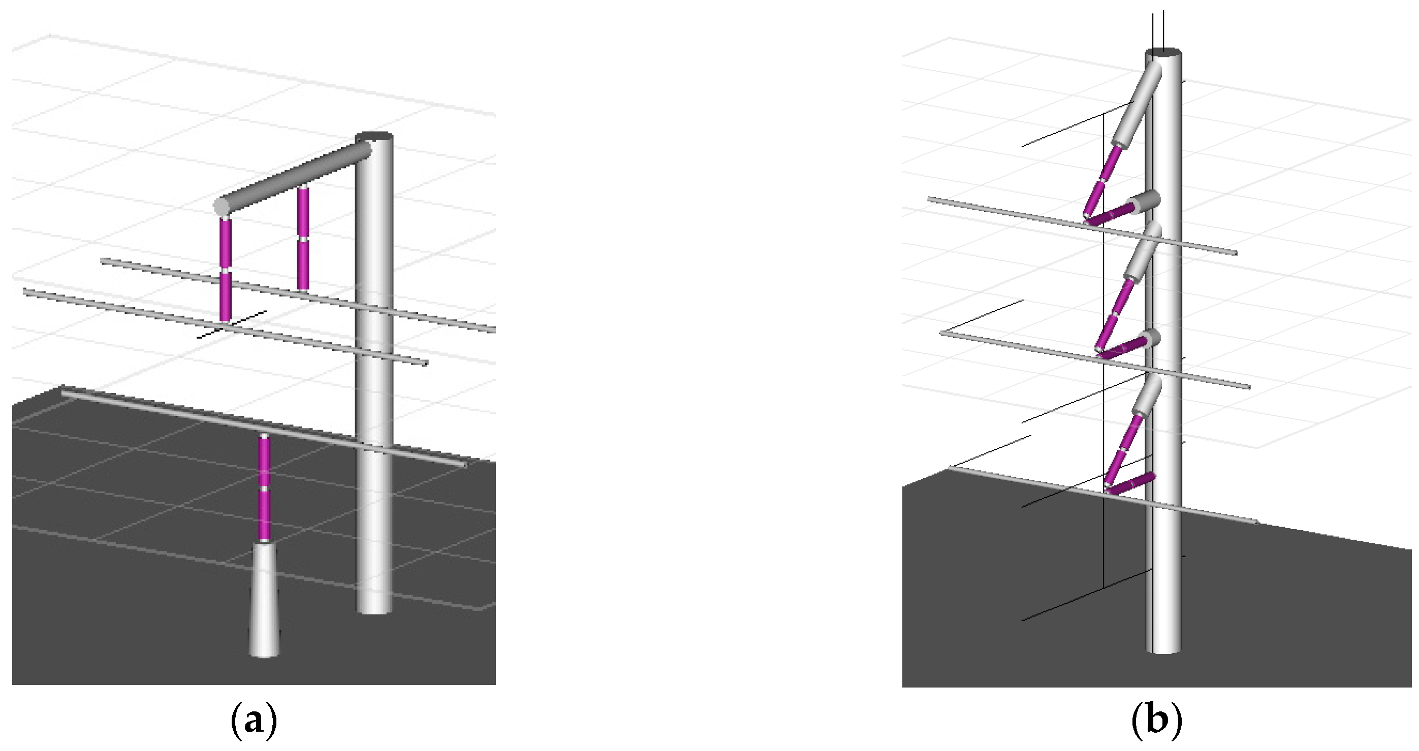
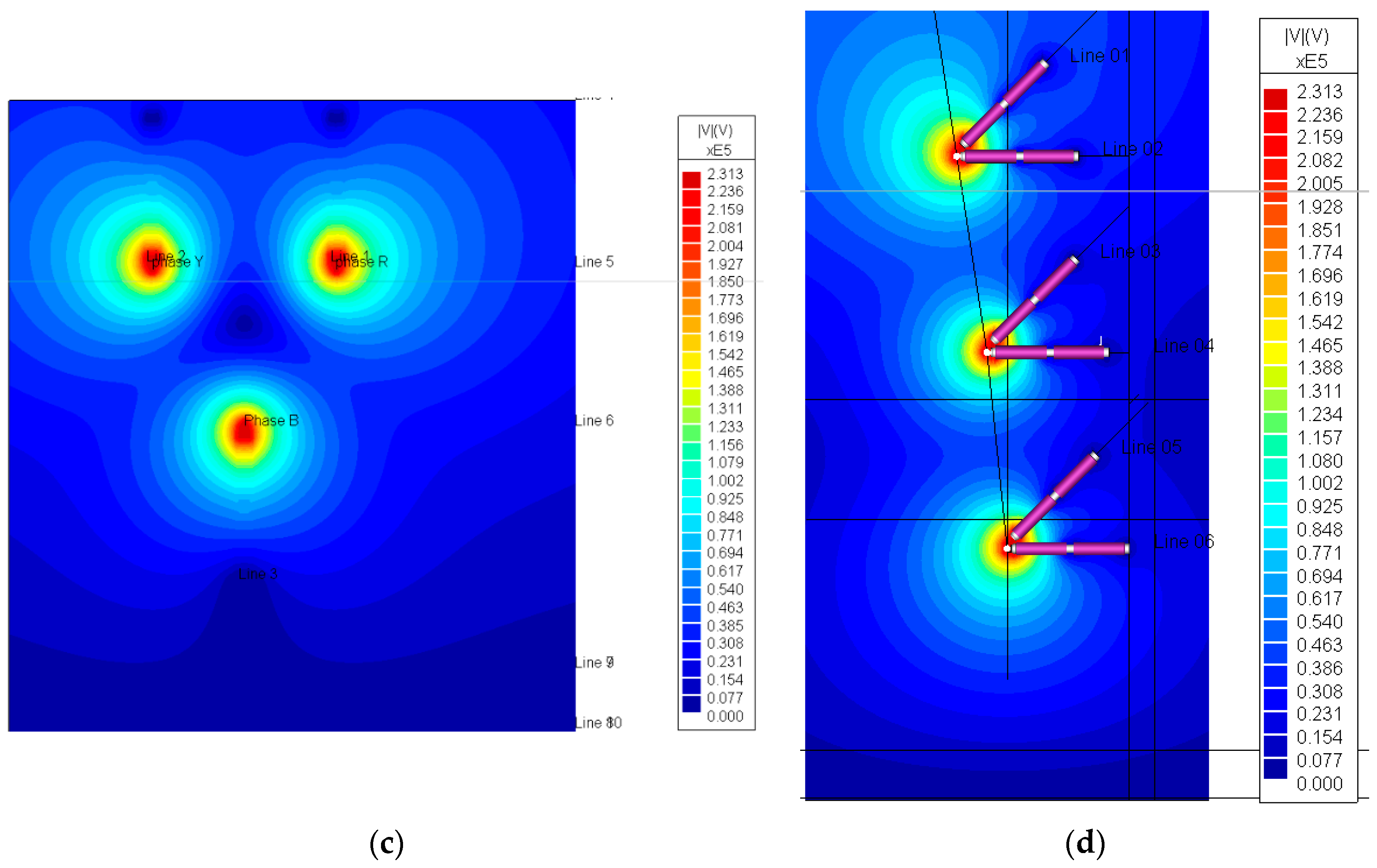
Figure 4.
Dimensions of delta (a) and vertical (b) busbar arrangements [14].
Figure 4.
Dimensions of delta (a) and vertical (b) busbar arrangements [14].

Figure 5.
Typical line-entry bay configuration. Lateral view (a) and the indication of volume occupation and longitudinal clearances between equipment (b).
Figure 5.
Typical line-entry bay configuration. Lateral view (a) and the indication of volume occupation and longitudinal clearances between equipment (b).

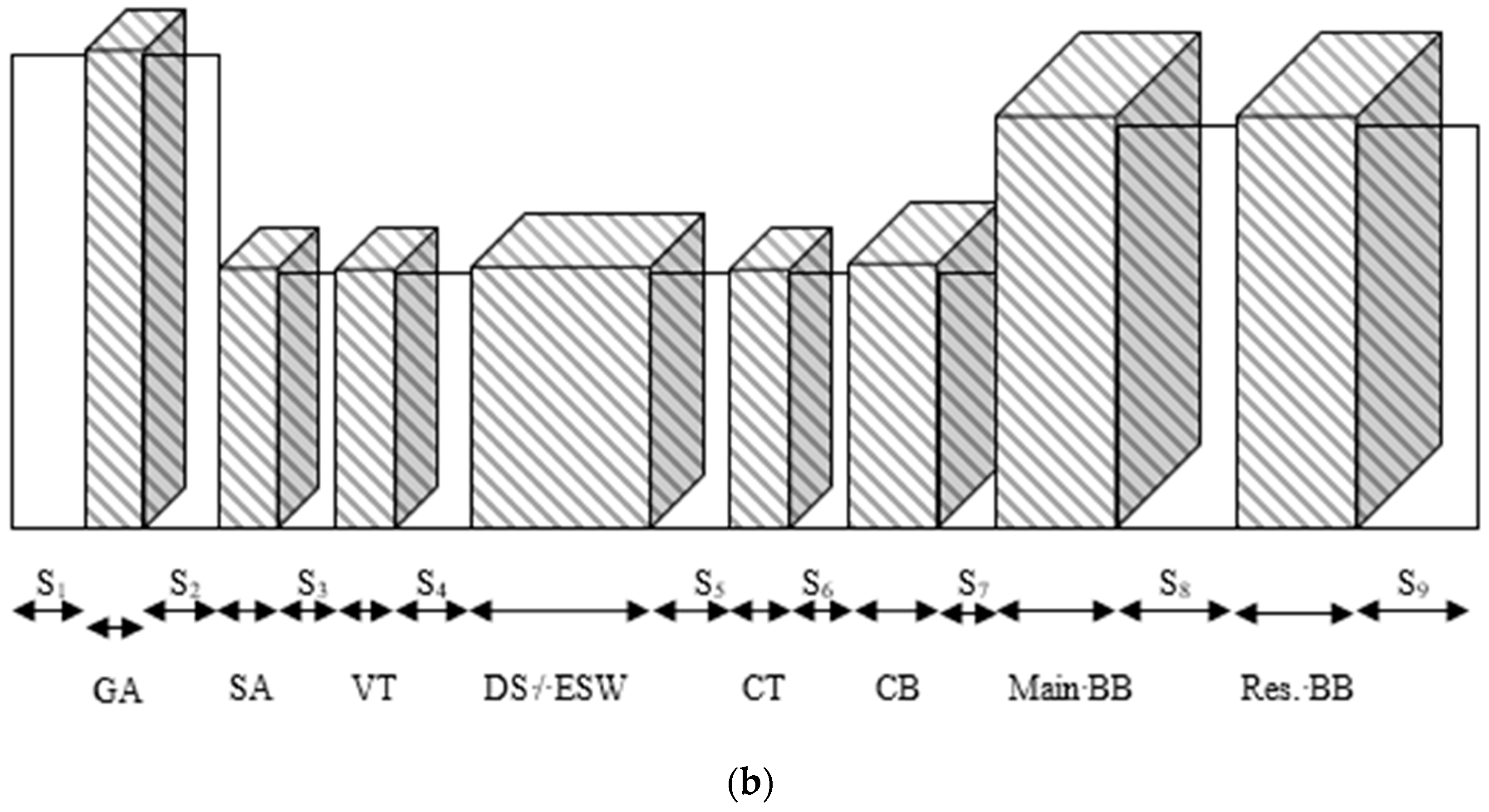
Figure 6.
Proposed line entry compact bay configuration.

Figure 7.
Single line diagram of a double busbar substation (400/132 kV). V1 to V8 nodes indicating the possible location of the SA installation.
Figure 7.
Single line diagram of a double busbar substation (400/132 kV). V1 to V8 nodes indicating the possible location of the SA installation.


Table 1.
Minimum air clearances and insulation levels (LIWV and SIWV) according to IEC 60071.
| Minimum Clearance | Existing Substation 1425/1050 kV [m] | Compact Substation 1050/850 KV [m] |
|---|---|---|
| phase-to-earth | 2.80 | 2.10 |
| phase-to-phase | 3.60 | 2.60 |
Table 2.
Busbar dimensions for the current UK system and the compact IEC systems (refer to Figure 2 for definitions).
Table 2.
Busbar dimensions for the current UK system and the compact IEC systems (refer to Figure 2 for definitions).
| Description | Existing Substation [m] | Compact Substation [m] |
|---|---|---|
| Minimum (Min.) clearances | ||
| C1—Min. phase-earth clearance | 2.80 | 2.10 |
| C2—Min. phase-phase clearance | 3.60 | 2.60 |
| Tolerance | ||
| T—Tool length (Safety tolerance) | 0.30 | 0.30 |
| PRv—Personal reach (vertical) | 2.40 | 2.40 |
| PRh—Personal reach (horizontal) | 1.50 | 1.50 |
| Safety | ||
| Safety Distance | 3.10 | 2.40 |
| SDv—Design clearance for safety (vertical) | 5.50 | 4.80 |
| SDh—Design clearance for safety (horizontal) | 4.60 | 3.90 |
| AIS Physical dimensions | ||
| a—Earthing frame height | 3.20 | 2.40 |
| b—Insulator height | 3.80 | 2.40 |
| c—Busbar phase separation | 5.00 | 2.67 |
| d—Bay side clearance | 3.60 | 2.17 |
| o—Busbar diameter | 0.14 | 0.14 |
| i—busbar center—ins. distance | 0.20 | 0.20 |
| h1—Buswork height (first layer) | 7.00 | 5.00 |
| Bay width | 17.48 | 10.39 |
| GIS Physical dimensions | GIS | |
| a—Earthing frame height | 3.00 | |
| c—Duct separation | 1.00 | |
| d—Bay side clearance | 2.10 | |
| o—GIS diameter | 0.14 | |
| i—GIS radius | 0.20 | |
| h1—GIS height | 7.00 | |
| Bay width | 6.80 |
Table 3.
Bay comparison.
| Busbar Arrangement | Bay Footprint Width (m) | Bay Height (m) |
|---|---|---|
| Existing design | 17.48 | 10.67 |
| Compact horizontal | 10.39 | 5.00 |
| Compact delta | 7.10 | 7.45 |
| Compact vertical | 5.34 | 15.47 |
| Compact vertical (cage) | 5.34 | 10.40 |
| GIS | 6.80 | 6.2 (to be indoor) |
Table 4.
List of plant components.
| Legend | Description | Component Length (m) | Component Clearance (m) |
|---|---|---|---|
| PLE | Point of Line Entry | 0 | 1.8 (S1, SC1) |
| GA | Gantry | 2.4 | 2.1 (S2, SC2) |
| SA | ZnO surge arrester | 1.4 | 3.35 (S3) |
| VT | Voltage transformer (conventional/non conventional) | 0.7 | 4.5 (S4, SC2) |
| DS/ESW | Disconnector isolator/earth switch | 5.3 | 1.7 (S5) |
| CT | Current transformer (conventional/non-conventional) | 0.9 | 2.1 (S6) |
| CB | Circuit breaker | 4.9 | 6.73 (S7, SC4) |
| Main BB | Main Busbar, including the isolator, vertical disconnector | 10.0 | 10.0 (S8) |
| Res. BB | Reserve busbar | 10.0 | 4.25 (S9) |
| Main C BB | Main Compact Busbar, includes the isolator, vertical disconnector | 1.5 | 4.5 (SC5) |
| Res. C BB | Reserve compact busbar | 1.5 | 4.25 (SC6) |
Table 5.
Length and area reduction of a compact bay.
| Layout | Bay Length | Footprint Reduction | ||
|---|---|---|---|---|
| (m) | Diff% | (m2) | Diff% | |
| Conventional | 72 | 0% | 1241 | 0% |
| Proposed Compact design | 37 | 48% | 336 | 73% |
Table 6.
Lightning overvoltages for existing and compact substations with surge arresters; Residual margin in percent.
Table 6.
Lightning overvoltages for existing and compact substations with surge arresters; Residual margin in percent.
| Existing Substation LIWL 1425 kV-4.16 pu | Compact Substation LIWL 1050 kV-3.06 pu | |||
|---|---|---|---|---|
| pu | LIPM% | pu | LIPM% | |
| V1 (L1–c1) | 2.7 | 34% | 2.7 | 12% |
| V2 (L1–c2) | 2.5 | 39% | 2.4 | 21% |
| V3 (L2–c1) | 2.6 | 37% | 2.4 | 20% |
| V4 (L2–c2) | 2.6 | 37% | 2.4 | 22% |
| V5 (L3–c1) | 3.0 | 27% | 2.3 | 24% |
| V6 (L3–c2) | 2.9 | 31% | 2.3 | 24% |
| V7 (SGT2) | 2.4 | 40% | 2.4 | 21% |
| V8 (SGT1) | 2.4 | 41% | 2.4 | 21% |
Table 7.
Switching overvoltages for existing and compact substations with surge arresters; residual margins in percentages.
Table 7.
Switching overvoltages for existing and compact substations with surge arresters; residual margins in percentages.
| Scenario | Existing Substation SIWL 1050kV-3.06pu | Compact substation SIWL 850kV-2.48pu | ||
|---|---|---|---|---|
| pu | SIPM% | p. | SIPM% | |
| A | 2.2 | 27% | 2.4 | 3% |
| A-TP | 4.1 | np 1 | 4.3 | np 1 |
| A-SA | 2.9 | 5% | 2.2 | 12% |
| B | 2.7 | 12% | 2.7 | np 1 |
| B-TP | 4.1 | np 1 | 4.4 | np 1 |
| B-SA | 2.9 | 4% | 2.0 | 17% |
1 np: not protected.
© 2018 by the authors. Licensee MDPI, Basel, Switzerland. This article is an open access article distributed under the terms and conditions of the Creative Commons Attribution (CC BY) license (http://creativecommons.org/licenses/by/4.0/).
Share and Cite
MDPI and ACS Style
Albano, M.; Haddad, A.M.; Griffiths, H.; Coventry, P. Environmentally Friendly Compact Air-Insulated High-Voltage Substations. Energies 2018, 11, 2492. https://doi.org/10.3390/en11092492
AMA Style
Albano M, Haddad AM, Griffiths H, Coventry P. Environmentally Friendly Compact Air-Insulated High-Voltage Substations. Energies. 2018; 11(9):2492. https://doi.org/10.3390/en11092492
Chicago/Turabian StyleAlbano, Maurizio, A. Manu Haddad, Huw Griffiths, and Paul Coventry. 2018. "Environmentally Friendly Compact Air-Insulated High-Voltage Substations" Energies 11, no. 9: 2492. https://doi.org/10.3390/en11092492
Note that from the first issue of 2016, this journal uses article numbers instead of page numbers. See further details here.