Flow and Temperature Characteristics of a 15° Backward-Inclined Jet Flame in Crossflow


1
Department of Mechanical Design Engineering, National Formosa University, Yunlin County 63246, Taiwan
2
Department of Mechanical Engineering, National Taiwan University of Science and Technology, Taipei 10607, Taiwan
*
Author to whom correspondence should be addressed.
Energies 2019, 12(1), 132; https://doi.org/10.3390/en12010132
Submission received: 10 November 2018
/
Revised: 24 December 2018
/
Accepted: 26 December 2018
/
Published: 31 December 2018
(This article belongs to the Special Issue Selected Papers from IEEE ICKII 2018)
Abstract
:The flow and flame characteristics of a 15° backward-inclined jet flame in crossflow were investigated in a wind tunnel. The flow structures, flame behaviors, and temperature fields were measured. The jet-to-crossflow momentum flux ratio was less than 7.0. The flow patterns were investigated using photography and Mie-scattering techniques. Meanwhile, the velocity fields were observed using particle image velocimetry techniques, whereas the flame behaviors were studied using photographic techniques. The flame temperatures were probed using a fine-wire R-type thermocouple. Three flame modes were identified: crossflow dominated flames, which were characterized by a blue flame connected to a down-washed yellow recirculation flame; transitional flames identified by a yellow recirculation flame and an elongated yellow tail flame; and detached jet dominated flames denoted by a blue flame base connected to a yellow tail flame. The effect of the flow characteristics on the combustion performance in different flame regimes is presented and discussed. The upwind shear layer of the bent jet exhibited different coherent structures as the jet-to-crossflow momentum flux ratio increased. The transitional flames and detached jet dominated flames presented a double peak temperature distribution in the symmetry plane at x/d = 60. The time-averaged velocity field of the crossflow dominated flames displayed a standing vortex in the wake region, whereas that of the detached jet dominated flames displayed a jet-wake vortex and a wake region source point.
1. Introduction
Jet flames in crossflow have been extensively investigated due to their widespread applications, especially in the design of gas turbine combustors and industrial burners. A jet flame in crossflow is classified as either wall-issued or stack-issued depending on the manner in which the fuel jet is injected into the crossflow. A wall-issued jet flame in crossflow [1,2] is created when the fuel jet is injected from an orifice on the wall into the crossflow, which commonly occurs in gas turbine combustors. A wall-issued jet flame in crossflow is influenced by the interactions of the issuing fuel jet, the crossflow, and the wall boundary layer. A stack-issued jet flame in crossflow [3,4] is produced when the fuel jet is emitted from an elevated stack into the crossflow, such as the flames created by stack flares. The aerodynamic interactions of the elevated stack, fuel jet, and crossflow play significant roles in determining the combustion characteristics of the jet flames in crossflow.
Based on the jet-to-crossflow momentum flux ratio, R, Huang and Chang [5] classified the stack-issued jet flame in crossflow into wake-stabilized and lifted jet flames. A wake-stabilized jet flame in crossflow is created when the fuel jet is ignited at low a jet-to-crossflow momentum flux ratio that falls below a critical value. The stack and jet provide favorable conditions for stabilizing the flames. The flame exists at a jet-to-crossflow momentum flux ratio of less than 100 before blow-off [6]. This flame is characterized by an appreciable down-washed recirculation flame. Huang and Chang [5] identified six flame modes in the flame stability regime of the wake-stabilized flames: a down-washed flame, flashing flame, developing flame, dual flame, flickering flame, and pre-blow-off flame. The dual flame showed improved combustion performance. Johnson et al. [7] measured the inefficiencies in a low-momentum non-premixed flame in crossflow. The inefficiencies were mainly found to consist of unburned fuel, which was emitted from the flame in a highly intermittent and spatially variable process. Johnson and Kostiuk [8] performed an analysis of the combustion products to determine the inefficiencies as a result of fuel stripping. They found that increasing the crossflow speed impacts the combustion efficiency, whereas increasing the jet exit velocity makes the flame less susceptible to the effects of the crossflow. A lifted jet flame in crossflow is created when the fuel jet is ignited at a high jet-to-crossflow momentum flux ratio that falls above a critical value [5]. The base of the resulting flame stabilizes at some stand-off height above the burner tube exit. The dominant feature in the flow-field of this flame is the presence of the counter-rotating vortices. Kalghatgi [9] obtained the stability characteristic curves for lifted jet flames in crossflow. Temperature measurements of lifted jet flames in crossflow were reported by Botros and Brzustowski [10].
In some cases due to combustor designs, the fuel jet is required to be issued into the crossflow from an inclined stack. The resulting flame is referred as an inclined/oblique stack-issued jet flame in crossflow. Few researchers have investigated the problem of an inclined stack-issued jet flame in crossflow compared to a transverse (perpendicularly issued jet into the crossflow) jet flame. Dan and Mungal [11] showed that forward-inclined stack-issued jet flames in crossflow (i.e., the stack facing the direction from which the crossflow issues) were short and more stable than backward-inclined stack-issued jet flames in crossflow (i.e., the stack facing the direction into which the crossflow issues). Kalghatgi [12] obtained the stability characteristic curves of an inclined jet flame in crossflow. The flame that was created by a forward-inclined stack was more resistant to blowout by the crosswind than that created by a backward-inclined stack counterpart. Han and Mungal [13] investigated the stabilization mechanism of a forward-inclined stack-issued jet flame. They observed that the jet flame with a higher crossflow velocity contained a lower liftoff height and was more stable than that created by a lower crossflow velocity.
This paper reports the flow and temperature characteristics of a jet flame in crossflow created by a low-backward inclination angle of the stack that have not been extensively addressed by previous researchers. The backward inclination angle of the stack in the wind tunnel was set as θ = 15°. The backward-inclination angle θ was the angle measured between the crossflow and jet flow. During the experiments, the crossflow Reynolds number was maintained at a constant of Rew = 2300, and the jet Reynolds number was varied within 0 ˂ Rej ˂ 13,000, hence the jet-to-crossflow momentum flux ratio was in the range of 0 ˂ R ˂ 7.0. The flame behaviors were investigated by the long- and short- exposure photography techniques. The flow patterns of the jet flames were examined using photography and Mie-scattering techniques, whereas the temperature fields were detected using an R-type thermocouple. The time-averaged velocity fields of the jet flame in crossflow were measured by the Particle image velocimetry (PIV) technique.
2. Experimental Methods
2.1. Apparatus
Figure 1 shows a schematic representation of the experimental setup. The experiments were performed in an open-loop, suction-type wind tunnel. The dimensions of the test section were 300 × 300 × 1100 mm3. The side walls and roof of the test section were made of transparent, thermal-resistive glass panels for visualizations and photography, whereas the floor was made of polished aluminium alloy plates. A centrifugal fan located behind the test section sucked the crossflow. Upstream of the test section, the crossflow was conditioned honeycombs, a series of mesh screens, and a 9:1 convergent nozzle. The crossflow velocity was monitored by a retractable pitot tube connected to a high-precision pressure transducer. The turbulence intensity of the crossflow as measured by a home-made, one-component hot-wire was within 0.25%. On the roof of the wind tunnel, a narrow slot was created for the insertion of the probes. The probes were positioned inside the test section by a computer-controlled three-dimensional traversing mechanism with step accuracy of 10 µm.
The burner tube was a stainless-steel tube. The internal diameter (d), external diameter (D), and length the burner tube are 5 mm, 6.4 mm, and 510 mm, respectively. In a vertical position within the test section, the burner tube penetrated a distance of 160 mm above the tunnel floor. The burner tube was connected to a nozzle assembly that was located beneath the test section. The nozzle assembly was carefully profiled into a fifth-order polynomial, and it had a contraction ratio of 900:1. The length of the nozzle was 300 mm. The fuel jet was conditioned through the honeycombs and a mesh screen within the nozzle assembly. The origin of the measurement coordinate system was positioned at the center tube’s exit plane.
The fuel used was commercial grade propane of the following composition: 95% C3H8, 3.5% C2H6, and 1.5% C4H10. The fuel was supplied from a high-pressure storage gas tank that contained a pressure regulator and a needle valve. It was passed through a high-pressure, flexible piping system, and a calibrated rotameter and was then fed into the nozzle assembly. The rotameter was calibrated by a high-precision electronic mass flowmeter.
2.2. Flame and Flow Visualizations
A digital camera (Nikon, Inc., Tokyo, Japan, Model D3200) was used to capture the long-exposure flame image. The color complementary metal oxide semi-conductor (CMOS) array and maximum resolution of this camera are 23.2 × 15.4 mm2 and 6016 × 4000 pixels, respectively. The flame images were taken at an exposure time of 2 s. To compute the characteristic length of the flames, an average of 30 images was used, which is equivalent to an exposure time of 60 s. The standard error in the average flame widths determined was within ±1.50 mm. The side view and top view instantaneous flame images were taken by a high-speed color camera (Photron Fastcam Inc., Tokyo, Japan, Model SA3), which had a CMOS sensor with a maximum resolution of 1024 × 1024 pixels. The camera’s frame rate was set to 2000 fps and its exposure time to 0.33 ms. The flow patterns were observed using the Mie-scattering technique. The fuel jet was seeded with 0.5 µm magnesium oxide (MgO) particles. The light source was from a 5 W solid state laser that had a wavelength of 532 ± 1 nm. The laser beam was converted into a triangular laser sheet of about 0.5 mm thickness using the cylindrical lenses. The laser sheet was illuminated in the symmetry plane of the flames. To acquire the flow images, the camera exposure time was adjusted to 0.2 ms, and the framing rate was set as 2000 fps.
2.3. PIV Measurements
The velocity fields were measured by a high-speed PIV system. The PIV system consisted of a light source, a high-speed camera, an electronic synchronizer, and PIV analysis software. The light source was obtained from a high-repetition-rate, dual-head, diode-pumped, neodymium-doped yttrium lithium fluoride pulsed laser. The electronic synchronizer externally triggered the pulsing laser at the double-pulsing mode with a pulse separation of 50 µs. The laser beams had a wavelength of 527 nm and maximum pulse rate of 20,000 pulses/s. The light energy per pulse of the laser was 10 mJ at 1 kHz. A light-sheet expander positioned at the laser head converted the laser beams into a triangular light sheet with a thickness of about 0.5 mm. To scatter the laser light, the fuel jet was seeded with 0.5-µm MgO particles. The camera had a 13.9 mm × 13.9 mm CMOS sensor. The maximum resolution of the camera was 1024 × 1024 pixels, which was mapped into a physical region of 150 × 150 mm. This resulted in a spatial resolution of about 146.5 × 146.5 µm/pixel. A total of 10,000 image pairs was acquired at a frame rate of 2500 fps. The cross-correlation technique proposed by Kean and Adrian [14] was employed to evaluate the two consecutive double-exposed image pairs using a PIV analysis software (IDT Inc., provision-XS PIV v3.12.1, Pasedena, USA). The interrogation window for PIV analysis was set as 32 × 32 pixels, with a 50% overlap. The displacement of the particles in the consecutive double-exposed images was maintained at less than 0.25 of the interrogation window length to reduce the velocity bias in high-velocity gradient regions, as suggested by Westerweel [15]. By adjusting the particle seed density for reliable measurements, at least four particle image pairs per interrogation spot were maintained. The predetermined number of vectors for PIV analysis was 2500. Spurious vectors were less than 2 percent per instantaneous field. During the PIV processing, error checks and interpolation routines were used to detect outliers. The outliers identified were replaced by regenerated interpolated values.
2.4. Temperature Measurements
The flame temperatures were measured by a homemade thermocouple (R-type). The thermocouple probe consisted of 125-µm diameter wires and a measuring bead of 175 µm. The wires were fitted into a ceramic tube of 1.3 mm diameter, which was securely held inside a stainless-steel tube for rigidity. The measuring bead extended 15 mm from the tip of the ceramic tube. A commercial data acquisition unit (Yokogawa Inc., Tokyo, Japan, model MX100) logged the electronic signals induced by the flame temperatures. For each measurement position investigated, the sampling frequency and time were 2 Hz and 60 s, respectively. The flame temperatures were recorded in the symmetry plane and in the transverse direction at different z levels. The temperature readings were not corrected for the radiation losses. An energy balance analysis Luo [16] expressions shows a deviation of the measured values from the actual values of approximately 50 °C for a flame temperature of 1600 °C. The uncertainty analysis of the standard error in the mean measured temperatures was within ±2 °C.
3. Results and Discussion
3.1. Flame Behaviors
Figure 2 shows the side-view, time-averaged flame images at θ = 15° for various jet-to-crossflow momentum flux ratios (R). The left column shows the direct shot flame images, whereas the right column displays the corresponding close-up images. Figure 2a,b show the flame images at a low R of R = 0.005 and 0.030, respectively. The flames display a blue flame that connects to a down-washed yellow recirculation flame in the −z direction. At this low R, the crossflow momentum is stronger than the jet momentum. The fuel jet is severely bent over in the crossflow direction as soon as it leaves the tube by the strong crossflow. Almost the entire fuel jet is entrained into the tube wake region, where it burns and creates these short flames. The flames with these characteristics are categorized as crossflow dominated flames and they exist for about R ˂ 0.040. These flames are similar in shape to those produced by the transverse stacks (θ = 0°) at a low R in the experiments of Gollahalli and Nanjundappa [17]. When the fuel jet momentum is increased above a critical value, the jet flames show a developed yellow tail flame and a down-washed yellow recirculation flame, as shown in Figure 2c,d,e for R = 0.095, 0.228, and 1.178, respectively. These flames are classified as transitional flames. The transitional flames are generated when some of the fuel jet combusts within the standing vortex in the wake region of the burner tube, which produces the recirculation flame. The remainder of the fuel jet burns toward the downstream region and creates the yellow tail flame. The transitional flames are denoted as partially yellowish necking flames when the neck flame (flame at the junction of the recirculation flame and tail flame) is partly yellow and partly blue, as shown in Figure 2c,d for R = 0.095 and 0.228, respectively. The partially yellowish necking flames exist for 0.04 ˂ R ˂ 0.35. These flames were not observed by Huang and Chang [5] for jet flames created by a perpendicular stack. When the neck flame is wholly blue, as displayed in Figure 2e for R = 1.178, the flames are called blue necking flames. The blue necking flames exist for 0.35 ˂ R ˂ 1.60. Figure 2f,g shows the flames at R = 2.011 and 4.586, respectively. The flames display a blue flame base that links to a yellow tail flame in the downstream region of the burner tube. The flames do not display the yellow recirculation flame. The flames are detached from the burner tube. These flames are categorized as detached jet dominated flames. At a high R, the jet momentum is strong enough to overcome the downwash effects created by the crossflow passing over the burner tube. Much of the fuel is transported into the downstream region, which results in the elongated yellow tail flames. When R is increased above a critical value of about R = 6.40, the flame stabilization region becomes unfavorable to sustain the combustion process and thus the flames blow-off. In previous studies on wake-stabilized jet flames in crossflow produced by perpendicular stack [5,6], stable detached jet flames from the burner tube were not sustained.
Figure 3 shows the corresponding time-averaged, top view flame images at θ = 15° for various jet-to-crossflow momentum flux ratios (R). The images were taken with the camera facing the −z direction at an exposure time of 2 s. The left column shows the direct shot flame images, whereas the right column are the close-up flame images. Figure 3a,b shows the flame images of the crossflow-dominated flames at R = 0.005 and 0.030, respectively. The flames display a yellow flame in the upstream region that corresponds to the recirculation flame and a blue reacting flame in the downstream. The flame tips are sharp. At R = 0.005, the yellow flame appears at the mid-plane location, and narrow blue flame sheets appear on the flame edges in the upstream region. The appearance of the blue flame sheets at the edges depicts the diffusion-controlled combustion characteristics of the flame, whereby intense mixing is confined at the fuel–air interface. Direct visual observations reveal the flame at R = 0.030 to contain the narrow blue flame sheets on the flame edges. However, the presence of an enlarged yellow recirculation flame obstructs the blue flame sheets from being seen in the presented images. The partially yellowish necking flames in the transitional regime mode appear wholly yellow, as shown in Figure 3c,d for R = 0.095 and 0.228. The blue flames seen in the side view images are obstructed in the top view images by the enlarged yellow flame underneath, indicating that these flames widen toward the −z direction. The blue necking flame depicts a yellow flame base followed by a wholly blue flame that connects to an enlarged yellow tail flame, as shown in Figure 3e for R = 1.178. The flame is narrow in the upstream and shows a gradual expansion toward the downstream region—initiating at about x/d = 7.5. The detached jet dominated flames depict a blue flame in the upstream region that similarly expands downstream and connects with an elongated yellow tail flame, as shown in Figure 3f,g for R = 2.011 and 4.586, respectively.
Figure 4 shows the variation of the time-averaged flame span width with R. In general, the width of the flames increases with the axial position for x/d ≤ 60 and R ≥ 0.5. In the near field at x/d = 5, the flame width shows almost constant values of about bf = 2d for R ≥ 0.5. At x/d = 20, the flame width increases; rapidly attains peak value in the partially yellowish necking flames (R = 0.095); and dips in transitional flame (R = 0.35). In the regime of the blue necking flames, the width increases with R for R ≤ 1.60. The width shows an insignificant rise in the regime of the detached jet dominated flames for R ≥ 1.60. At x/d = 40 and 60, the width rises with R in the regime of the crossflow dominated- and transitional flames for R ≤ 1.60. For R > 1.60, the width displays an insignificant rise with R in the regime of the detached jet dominated flame.
Figure 5 shows the process of a flame blow-off at about R = 6.40. The flame extinction process begins at the base of the blue flame zone. At blow-off, the blue flame base becomes unstable and starts to oscillate violently. The base of the flame starts to move to the downstream region, whereas the whole flame shrinks. The flames’ luminosity continues diminishing downstream. After some distance, the yellow flame disappears and leaves a blue flamelet that keeps traveling downstream. Finally, the blue flamelet diminishes, hence completing the flame extinction process. Huang and Chang [5] observed a similar flame extinction process for transverse jet flames, Huang et al. [18,19] for acoustically excited transverse jet flames, and Wang et al. [20] for lifted transverse jet flames in crossflow. Figure 6 shows the axial position of the blue flame base during the blow-off process. From 0.032 s to 0.176 s, the detached blue flame base moves linearly downstream at a speed of approximately 2.80 m/s while containing the yellow and blue flames. Beyond x/d = 90, the blue flamelet travels downstream at a speed of about 4.20 m/s and disappears at the axial location of about x/d = 160. The flame blow-off process shows that the flame extinguishes when the stabilization region can no longer sustain the combustion process as the fuel jet velocity rises above a critical value. It is worth noting that wake-stabilized jet flames in crossflow at θ = 15° in the present study are less stable than their counterpart transverse jet flames in crossflow [21]. Huang and Wang [21] documented stable jet flames in crossflow for R > 10.0. The faster blow-off when θ increases is due to the reduction in magnitude and physical range of the low pressure zone in the tube wake where the flames stabilize [22].
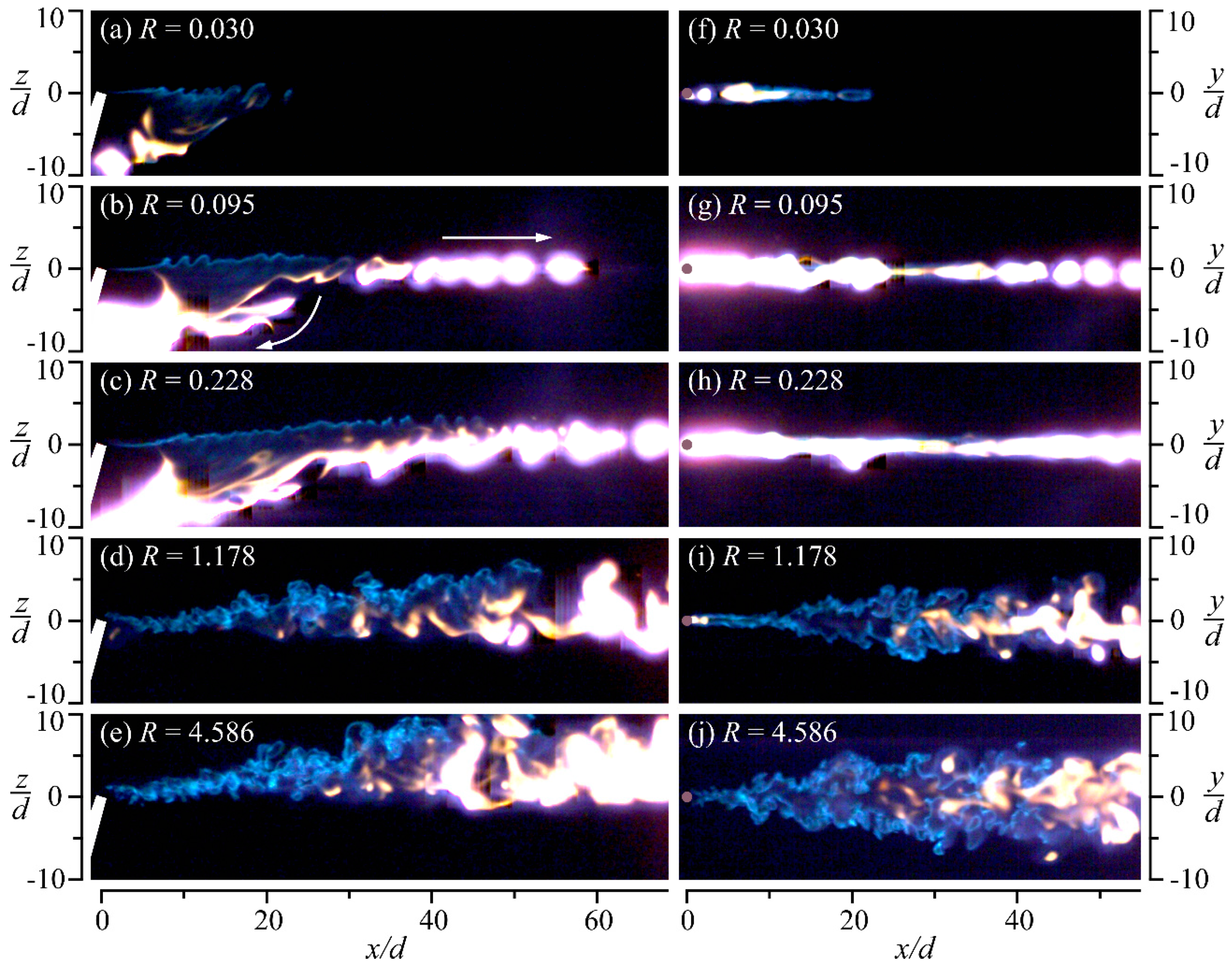
Figure 7 shows the instantaneous flame images at θ = 15° for various R. The left column shows the flame images of the side view, while the right column shows the corresponding flame images of the top view. The crossflow dominated flame shown in Figure 7a at R = 0.030 displays wrinkles on the upper surface of the flame. The flame wrinkles are generated by the upwind shear layer vortices [6]. Watching the captured flame videos on a computer shows the recirculation flame moving in the direction of clockwise to the burner tube. Meanwhile, watching the flame videos of the corresponding top view flame image shown in Figure 7f shows that the yellow flame travels upstream, while the blue flame travels downstream—exhibiting a puffing motion (the flame fragments in the downstream). Kimilu et al. [19] observed similar phenomenon of flame fragmentation for non-excited and low-excited jet flames in crossflow. Figure 7b,c show the instantaneous flames of the partially yellowish necking flames at R = 0.095 and 0.228, respectively. The upper flame surface similarly displays wrinkles. The recirculation flame is one intact flame that travels in a clockwise manner when observed in the flame movements. The counterpart top view flames shown in Figure 7g,h appear wholly yellow. The flame movements show that part of the flame moves toward the burner tube, which corresponds to the recirculation flame, whereas the rest of the flame travels downstream—exhibiting a puffing phenomenon. Figure 7d,i shows the blue necking flame at R = 1.178. The flame appears almost wholly turbulent. Observing the flame movements, the tail flame travels downstream, and the small yellow recirculation flame travels upstream. The flame image shows the blue flame sheets at the edges of the flame and a hollow center. This is a feature typical of non-premixed flames. The detached jet dominated flame shown in Figure 7e,j is fully turbulent. The flame movements show that the flame travels downstream. Similarly, the top-view flame image shown in Figure 7j shows typical diffusion flame characteristics of two blue flame sheets at the edges of the flame and a hollow center.
3.2. Flow Behaviors
Figure 8 shows the instantaneous flow patterns in the symmetry plane (y/d = 0) for various R. The bent-over jet displays coherent structures in the upwind shear layer. The crossflow dominated flame at R = 0.030 and the partially yellowish necking flame at R = 0.228 display coherent vortices appearing as roll-ups that move toward the downstream before they break up into small-scale structures. These vortices are designated as mixing layer-type vortices [23]. For the crossflow dominated flame at R = 0.030, much of the fuel is entrained into the tube wake region, where it combusts to generate the yellow recirculation flame. At R = 0.228, which corresponds to the partially yellowish necking flame, part of the fuel flows into the tube wake region to support the recirculation flame, and the rest burns downstream to produce the yellow tail flame. At R = 0.345, the upwind shear layer exhibits vortices that have the shape of a mushroom, as shown in Figure 8c. These vortices are referred to as mushroom-like vortices. The vortices are enlarged, and the distance between them is wider than that in the mixing layer-type vortices. The resulting flame produced by the bent jet with mushroom type vortices shows that the tail flame is divided into an upper tail and a lower tail. This flame was named the dual flame [5], and it exhibits a shortened total flame length and a more bluish flame. At R = 1.178, 2.011, and 4.586, the upwind shear layer displays counterclockwise rotating vortices that sometimes appear intermittently and are called jet-type vortices. For the flame at R = 1.178, which corresponds to the blue necking flame, the burner tube and the bent over jet act as the flame holders and provide favorable conditions for the combustion process, as shown in Figure 8d. However, the jet body becomes the flame holder for the detached jet dominated flames, as depicted in Figure 8e,f for R = 2.011 and 4.586, respectively. The shear layer vortices of the bent jet flame are dominated by the crossflow at low jet-to-crossflow momentum flux ratio (R < 1.0). However, the shear layer vortices of the bent jet flame are dominated by jet at high R (R > 1.0).
The time-averaged velocity streamlines and vector plots obtained by PIV in the near wake region in the symmetry plane (y/d = 0) at various R are shown in Figure 9. At low R, the flame characteristics are the crossflow dominated- and partially yellowish necking flame modes. The crossflow strongly bends over the jet streamlines in a large angle upon emerging from the tube, as shown in Figure 9a,b for R = 0.030 and 0.228, respectively. Some streamlines bend downwards and then turn toward the upstream in the tube wake region, creating a standing vortex. This vortex is responsible for the stabilization of these flames. Combustion within the recirculation zone leads to the creation of the large downwash recirculation flame, as depicted in Figure 2b–d. The rest of the streamlines propagate downstream and are responsible for the formation of the yellow tail flame observed in the transitional regime. Similar streamline patterns at low R were observed in non-reacting transverse jets [24]. Figure 9c shows the superimposed velocity streamlines and vector plots at R = 1.178 (blue necking flames). The streamlines penetrate deeper into the crossflow before they fully align into the crossflow direction than in the situations of the low R cases due to the increased jet momentum. A tube-wake bifurcation line appears in the flow field, standing at about x/d = 10. A clockwise-rotating vortex appears in the wake of the jet. The flow field of the detached jet dominated flame at R = 2.011, shown in Figure 9d, presents a clockwise rotating jet-wake vortex and a source point. Streamlines originating from the source point propagate radially. A tube-wake bifurcation line appears at about x/d = 6. On the left of the source point and tube-wake bifurcation line, the streamlines move toward the upstream, and some terminate at the burner tube, whereas some reverse toward the downstream by enclosing the jet-wake vortex. The streamlines on the right of the source point and tube-wake bifurcation line propagate toward the downstream area. The tube-wake vortex (as shown in Figure 9a) appears at low R. It is formed by the interaction of tube wake and downwash effect. However, the jet-wake vortex (as shown in Figure 9d) exhibits at high R. It is induced by the combined effects of jet shear and jet wake.
3.3. Temperature Distributions
Figure 10 reveals the time-averaged temperature distributions of the crossflow dominated flame at x/d = 5 and 15. A double-peak temperature profile presents at x/d = 5. The two temperature peaks and a dip between them shows that the type of combustion process occurring is diffusion controlled. The intense chemical reactions are confined at the vertices of the standing vortex resulting in the peak temperatures there. The dip is produced because of inadequate oxygen penetrating to the vortex center. Gollahalli and Nanjundappa [17] documented similar profiles for transverse jet flames in crossflow. At x/d = 15, the dip in the temperature profile detected at x/d = 5 disappears and the profile appears like a top-hat. Moreover, the peak temperatures at x/d = 15 are higher than those at x/d = 5, which indicates that the chemical mixing reactions are better at x/d =15 than at x/d = 5. Indeed, from the flame visualization images shown in Figure 2b,i, the location x/d = 15 contains the blue flame, which is like the premixed flames. These results of the symmetry temperature measurements indicate that the crossflow dominated flame consists of diffusion-controlled combustion reactions and premixed-like combustion characteristics.
Figure 11 shows the time-averaged temperature distributions in the symmetry plane for R = 0.228, 1.178, and 2.011 at x/d = 5, 30, and 60, respectively. At x/d = 5, the width of the temperature distributions decreases as R increases due to the narrowing and diminishing of the recirculation flame, as seen in Figure 2. The flame at R = 0.228 (partially yellowish necking flame) shows the diffusion-controlled combustion feature of a double-peak profile, as shown in Figure 11a. The flames at a high R of R = 1.178 and 2.011 show a single-peak temperature distribution, as depicted in Figure 11b,c, respectively. For the flames at R = 1.178 and 2.011, the location x/d = 5 contains the blue flame, which is similar to the premixed-like flame in the near field obtained by Huang et al. [18] for highly acoustically excited transverse jet flames that also displayed the same temperature distribution. Measuring the flame temperatures at x/d = 30, the profiles show skewed temperature distributions with peak temperatures detected at the lower surface of the flame, as shown in Figure 11d–f for R = 0.228, 1.178, and 2.011, respectively. The reduced temperatures at the upper surface of the flame are induced by the presence of the cold fuel, as shown in the superimposed instantaneous images of the jet with the flame in Figure 8, whereby the fuel appears above the flame surface. Strong chemical reactions between the fuel and fresh air are confined at the lower surface of the flame and thus cause the presence of the peak temperatures there. The temperature distributions at x/d = 60 show a double-peak profile for R = 0.228, 1.178, and 2.011, as shown in Figure 11g–i, respectively. At R = 0.228, the two peak temperatures are almost of equal magnitudes. Almost all fuel is expected to have disappeared in the far field at x/d = 60 and high temperature-lean mixtures are retained on the upper and lower surfaces of the flame, while cool temperature-rich mixtures are retained in the flame center. At a high R of R = 1.178 and 2.011, the lower peak is higher than the upper peak. At x/d = 60 for R = 1.178 and 2.011, the counter-rotating vortex pairs [25] are expected to be present and developed in the flow field of these flames. The peak temperatures at the lower surface of the flame are produced by the entrainment and mixing processes by the counter-rotating vortex pairs. Their counterpart upper-peak temperatures are produced by the entrainment and mixing processes as a result of the shearing of the fuel jet and the crossflow. It can be deduced that the entrainment and mixing mechanism by the counter-rotating vortex pairs is superior to that by the shearing processes because the lower surface has higher temperatures. The dip at the center of the flame is because of the influence of the retained cool temperature-rich mixtures.
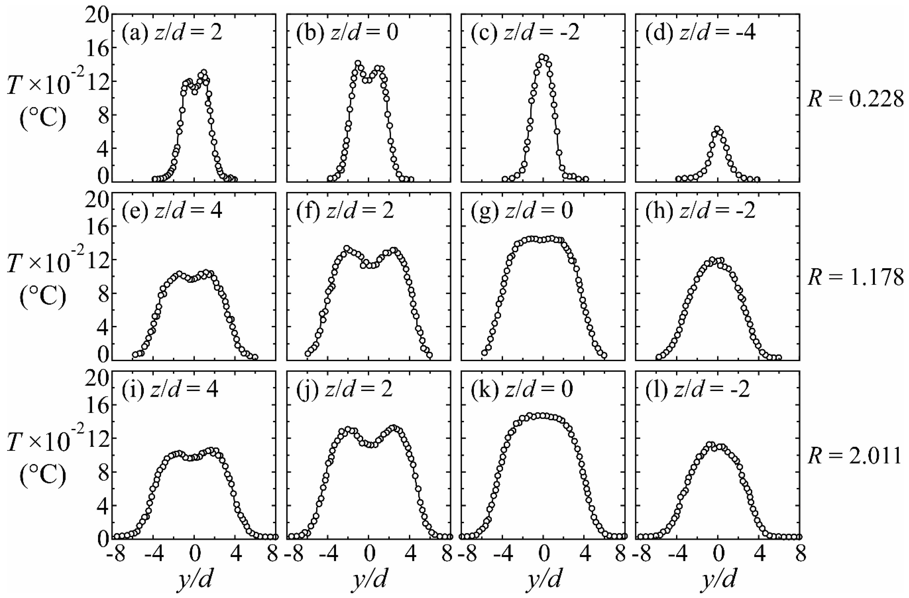
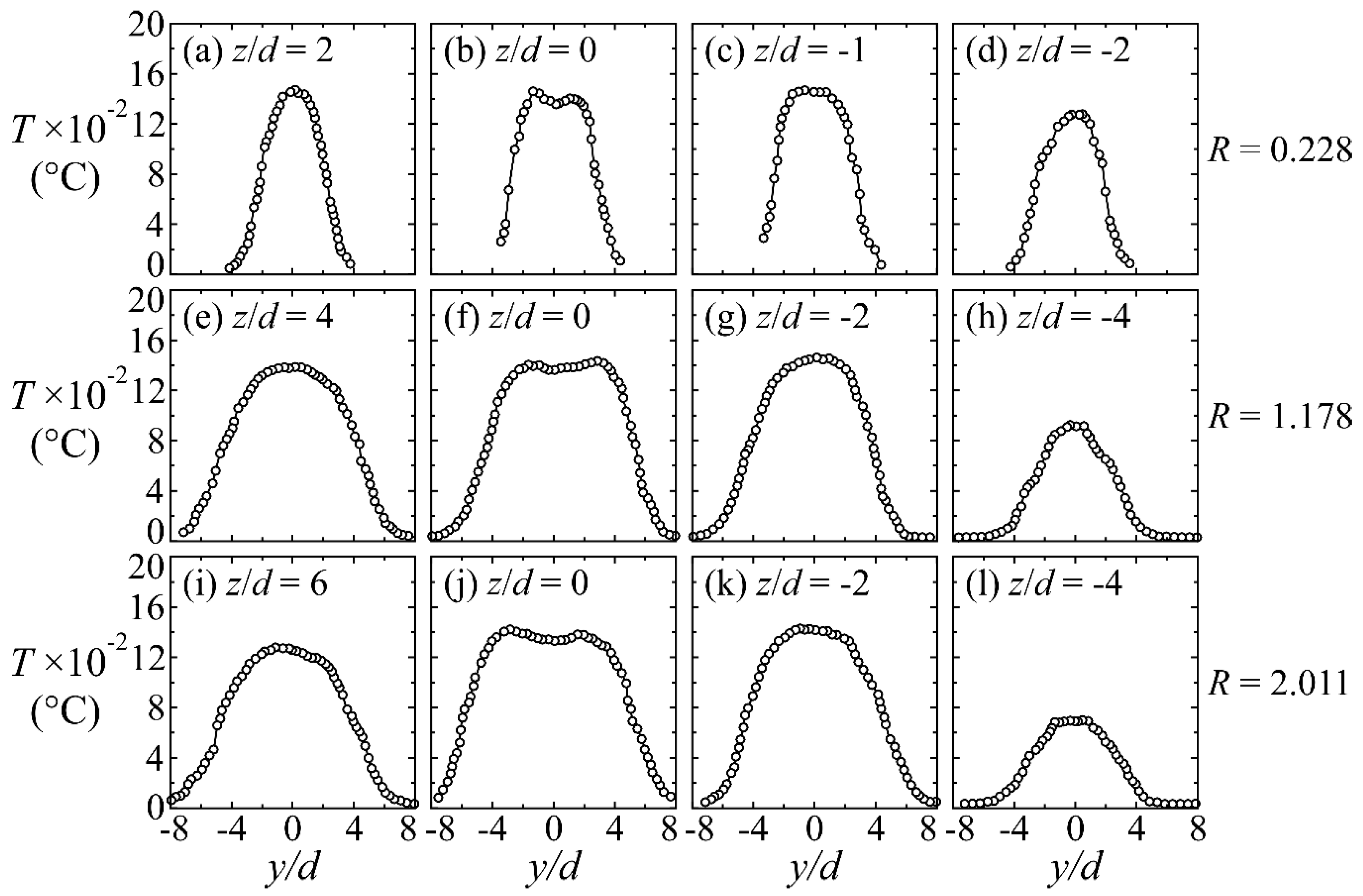
Figure 12 shows the time-averaged temperature distributions in the transverse direction across various z levels of the flames at x/d = 30 for R = 0.228, 1.178, and 2.011. At the upper surface of the flames, the temperature distributions display twin-peak profiles, as shown in Figure 12a,b,e,f,i,j for R = 0.228, 1.178, and 2.011, respectively. The dips in the temperature distributions are induced by the presence of cool temperature-rich mixtures at the upper surface of the flames in the symmetry plane, as shown in Figure 8. Combustion reactions are confined at the edges of the flame, where the chemical reactions are intense. The lower surface of the flame contains high temperature-lean mixtures, and the profiles show Gaussian-like profiles similar to those of the premixed flames, as shown in Figure 12c,d,g,h,k,l for R = 0.228, 1.178, and 2.011, respectively. At x/d = 60, the upper surface of the flames presents Gaussian-like temperature distributions, as observed in Figure 13a,e,i for R = 0.228, 1.178, and 2.011, respectively, which are induced by the shearing processes. Twin-peak temperature distributions are detected in the middle of the flame, which indicates that the combustion reactions at the flame center are diffusion controlled. The temperature distributions are Gaussian-like at the lower surface of the flames, as exhibited in Figure 13c,d,g,h,k,l for R = 0.228, 1.178, and 2.011, respectively. The presence of the counter-rotating vortices [25] at a high R is responsible for the premixed-like characteristics of a Gaussian profile for the flames at R = 1.178 and 2.011 at the lower surface.
4. Conclusions
This paper presents the flow and temperature characteristics of a stack-issued, backward-inclined jet flame in a crossflow. The backward inclination angle was set as θ = 15°. Three main flame modes are identified by varying the jet-to-crossflow momentum flux ratio: crossflow dominated flames, transitional flames, and detached jet dominated flames. The crossflow dominated flames are the short flames that are consisting of a blue flame connected to a down-washed yellow recirculation flame. A standing vortex in the wake region stabilizes the flames on the burner tube. The transitional flames consist of a yellow recirculation flame and a yellow tail flame. When the neck region of the transitional flames is partly yellow and partly blue, the flames are denoted as partially yellowish necking flames, and when the neck region appears wholly blue, the flames are called blue necking flames. The detached jet dominated flames are identified by a blue flame base, an elongated yellow tail flame, and an absence of the down-washed yellow recirculation flame. The detached jet dominated flames stabilize on the jet body.
The flame blow-off phenomenon initiates at the flame base and consists of two stages: The first stage involves the detached jet moving downstream while containing the blue and yellow flames. The second stage involves the shrunk blue flamelet traveling downstream until it vanishes. The flow patterns affect the temperature distribution in different flame modes. The temperature distributions in the symmetry plane of the crossflow dominated flame (R = 0.030) and the partially yellow neck flame (R = 0.228) show a double peak profile in the fuel recirculation area in the near field at x/d = 5. Meanwhile, those of the blue necking flame (R = 1.178) and detached jet dominated flame (R = 2.011) show a single peak profile. At x/d = 30, the partially yellowish necking flame, the blue necking flame, and the detached jet dominated flame have peak temperatures at the lower surface of the flame, where the chemical reactions are superior, while the upper surface has low temperatures due to the cold fuel quenching effect. In the far field at x/d = 60, these flames show peaks at the edges and a dip at the center, indicating that combustion reactions take place actively on the edges of the flames and cool temperature-rich mixtures are retained in the flame center. The time-averaged PIV results show a standing vortex in the wake region of the crossflow-dominated flames, whereas the detached jet-dominated flames display a jet-wake vortex and a source point.
Author Contributions
C.M.H. proposed the research topic, designed the experimental setup and methods, and organized the paper. D.B.M. carried out the experimental measurement and analyzed the data. C.M.H. and D.B.M. contributed to the writing of the manuscript. W.C.J. took part in image processing. All authors have read and approved the final manuscript.
Funding
The research received no external funding.
Conflicts of Interest
The authors declare no conflict of interest.
Nomenclature
| bf | Flame span width, mm. |
| D | External diameter of burner tube, 6.4 mm. |
| d | Internal diameter of burner tube, 5.0 mm. |
| L | Total length of burner tube, 510 mm. |
| R | Jet-to-crossflow momentum flux ratio (=ρjuj2/ρwuw2). |
| Rej | Jet flow Reynolds number (=ujd/νj). |
| Rew | Crossflow Reynolds number (=uwD/νw). |
| T | Time-averaged flame temperature, °C. |
| uj | Bulk velocity at exit of burner tube (4Qj/πd2), m/s. |
| uw | Crossflow velocity, m/s. |
| x | Cartesian coordinate in axial direction. |
| y | Cartesian coordinate in cross-stream direction. |
| z | Vertical coordinate. |
| θ | Backward-inclination angle of burner tube. |
| ρj | Fuel jet density, kg/m3. |
| ρw | Density of crossflow air, kg/m3. |
| νj | Kinematic viscosity of fuel jet, m2/s. |
| νj | Kinematic viscosity of crossflow air, m2/s. |
References
- Hasselbrink, E.F.; Mungal, M.G. Transverse jets and jet flames. Part 1. Scaling laws for strong transverse jets. J. Fluid Mech. 2001, 443, 1–25. [Google Scholar] [CrossRef]
- Karagozian, A.R. The flame structure and vorticity generated by a chemically reactingtransverse jet. AIAA J. 1986, 24, 1502–1507. [Google Scholar] [CrossRef]
- Bourguignon, E.; Johnson, M.R.; Kostiuk, L.W. The use of a closed-loop wind tunnel for measuring the combustion efficiency of flames in a cross flow. Combust. Flame 1999, 119, 319–334. [Google Scholar] [CrossRef]
- Brzustowski, T.A.; Gollahalli, S.R.; Sullivan, H.F. The Turbulent Hydrogen Diffusion Flame in a Cross-wind. Combust. Sci. Technol. 1975, 11, 29–33. [Google Scholar] [CrossRef]
- Huang, R.F.; Chang, J.M. The stability and visualized flame and flow structures of a combusting jet in cross flow. Combust. Flame 1994, 98, 267–278. [Google Scholar] [CrossRef]
- Huang, R.F.; Chang, J.M. Coherent structure in a combusting jet in crossflow. AIAA J. 1994, 32, 1120–1125. [Google Scholar] [CrossRef]
- Johnson, M.R.; Wilson, D.J.; Kostiuk, L.W. A Fuel Stripping Mechanism for Wake-Stabilized Jet Diffusion Flames in Crossflow. Combust. Sci. Technol. 2001, 169, 155–174. [Google Scholar] [CrossRef]
- Johnson, M.R.; Kostiuk, L.W. Efficiencies of low-momentum jet diffusion flames in crosswinds. Combust. Flame 2000, 123, 189–200. [Google Scholar] [CrossRef]
- Kalghatgi, G.T. Blow-Out Stability of Gaseous Jet Diffusion Flames Part II: Effect of Cross Wind. Combust. Sci. Technol. 1981, 26, 241–244. [Google Scholar] [CrossRef]
- Botros, P.E.; Brzustowski, T.A. An experimental and theoretical study of the turbulent diffusion flame in cross-flow. Symp. (Int.) Combust. 1979, 17, 389–398. [Google Scholar] [CrossRef]
- Han, D.; Mungal, M.G. Simultaneous measurements of velocity and CH distribution. Part II: Deflected jet flames. Combust. Flame 2003, 133, 1–17. [Google Scholar] [CrossRef]
- Kalghatgi, G.T. Blow-Out Stability of Gaseous Jet Diffusion Flames: Part III—Effect of Burner Orientation to Wind Direction. Combust. Sci. Technol. 1982, 28, 241–245. [Google Scholar] [CrossRef]
- Han, D.H.; Mungal, M.G. Stabilization in turbulent lifted deflected-jet flames. Proc. Combust. Inst. 2002, 29, 1889–1895. [Google Scholar] [CrossRef]
- Keane, R.D.; Adrian, R.J. Theory of cross-correlation analysis of PIV images. Appl. Sci. Res. 1992, 49, 191–215. [Google Scholar] [CrossRef]
- Westerweel, J. Fundamentals of digital particle image velocimetry. Meas. Sci. Technol. 1997, 8, 1379–1392. [Google Scholar] [CrossRef]
- Luo, M.C. Effects of radiation on temperature measurement in a fire environment. J. Fire Sci. 1997, 15, 443–461. [Google Scholar]
- Gollahalli, S.R.; Nanjundappa, B. Burner wake stabilized gas jet flames in cross-flow. Combust. Sci. Technol. 1995, 109, 327–346. [Google Scholar] [CrossRef]
- Huang, R.F.; Kimilu, R.K.; Hsu, C.M. Effects of jet pulsation intensity on a wake-stabilized non-premixed jet flame in crossflow. Exp. Therm. Fluid Sci. 2016, 78, 153–166. [Google Scholar] [CrossRef]
- Kimilu, R.K.; Huang, R.F.; Hsu, C.M. Non-Premixed Burner-Attached Jet Flames in Crossflow Pulsed at Resonance Frequency. J. Propul. Power 2016, 33, 1332–1350. [Google Scholar] [CrossRef]
- Wang, Q.; Hu, L.; Yoon, S.H.; Lu, S.; Delichatsios, M.; Chung, S.H. Blow-out limits of nonpremixed turbulent jet flames in a cross flow at atmospheric and sub-atmospheric pressures. Combust. Flame 2015, 162, 3562–3568. [Google Scholar] [CrossRef] [Green Version]
- Huang, R.F.; Wang, S.M. Characteristic flow modes of wake-stabilized jet flames in a transverse air stream. Combust. Flame 1999, 117, 59–77. [Google Scholar] [CrossRef]
- Kolla, H.; Grout, R.W.; Gruber, A.; Chen, J.H. Mechanisms of flame stabilization and blowout in a reacting turbulent hydrogen jet in cross-flow. Combust. Flame 2012, 159, 2755–2766. [Google Scholar] [CrossRef]
- Huang, R.F.; Lan, J. Characteristic modes and evolution processes of shear-layer vortices in an elevated transverse jet. Phys. Fluids 2005, 17, 034103. [Google Scholar] [CrossRef]
- Huang, R.F.; Hsieh, R.H. An experimental study of elevated round jets deflected in a crosswind. Exp. Therm. Fluid Sci. 2002, 27, 77–86. [Google Scholar] [CrossRef]
- Andreopoulos, J.; Rodi, W. Experimental investigation of jets in a crossflow. J. Fluid Mech. 1984, 138, 93–127. [Google Scholar] [CrossRef]
Figure 1.
Experimental setup.

Figure 2.
Flame appearances from side view. Left column: Direct shot; right column: Close-up. Exposure time = 2 s. θ = 15°.
Figure 2.
Flame appearances from side view. Left column: Direct shot; right column: Close-up. Exposure time = 2 s. θ = 15°.

Figure 3.
Typical flame images. Left column: Direct shot; right column: Close-up. Exposure time = 2 s. θ = 15°.
Figure 3.
Typical flame images. Left column: Direct shot; right column: Close-up. Exposure time = 2 s. θ = 15°.

Figure 4.
Variation of flame span width. θ = 15°.

Figure 5.
Flame blow-off process. Exposure time = 8 ms. θ = 15°, and R = 6.40.

Figure 6.
Position of the blue flame base during blow-off. θ = 15°.

Figure 7.
Instantaneous flame images. Left column: side view; right column: top view. Exposure time = 0.33 ms. Frame rate = 2000 fps. θ = 15°.
Figure 7.
Instantaneous flame images. Left column: side view; right column: top view. Exposure time = 0.33 ms. Frame rate = 2000 fps. θ = 15°.

Figure 8.
Instantaneous flow pattern and flame images in the symmetry plane (y/d = 0). Exposure time = 0.2 ms. Frame rate = 2000 fps. θ = 15°.
Figure 8.
Instantaneous flow pattern and flame images in the symmetry plane (y/d = 0). Exposure time = 0.2 ms. Frame rate = 2000 fps. θ = 15°.

Figure 9.
Time-averaged velocity vectors and streamlines in the symmetry plane. θ = 15°.

Figure 10.
Time-averaged temperature distributions at R = 0.030. θ = 15°.

Figure 11.
Time-averaged temperature distributions at R = 0.228, 1.178, and 2.011. θ = 15°.

Figure 12.
Time-averaged temperature distributions at x/d = 30. R = 0.228, 1.178, and 2.011. θ = 15°.
Figure 12.
Time-averaged temperature distributions at x/d = 30. R = 0.228, 1.178, and 2.011. θ = 15°.

Figure 13.
Time-averaged temperature distributions. R = 0.228, 1.178, and 2.011. θ = 15°.

© 2018 by the authors. Licensee MDPI, Basel, Switzerland. This article is an open access article distributed under the terms and conditions of the Creative Commons Attribution (CC BY) license (http://creativecommons.org/licenses/by/4.0/).
Share and Cite
MDPI and ACS Style
Hsu, C.M.; Mosiria, D.B.; Jhan, W.C. Flow and Temperature Characteristics of a 15° Backward-Inclined Jet Flame in Crossflow. Energies 2019, 12, 132. https://doi.org/10.3390/en12010132
AMA Style
Hsu CM, Mosiria DB, Jhan WC. Flow and Temperature Characteristics of a 15° Backward-Inclined Jet Flame in Crossflow. Energies. 2019; 12(1):132. https://doi.org/10.3390/en12010132
Chicago/Turabian StyleHsu, Ching Min, Dickson Bwana Mosiria, and Wei Chih Jhan. 2019. "Flow and Temperature Characteristics of a 15° Backward-Inclined Jet Flame in Crossflow" Energies 12, no. 1: 132. https://doi.org/10.3390/en12010132
Note that from the first issue of 2016, this journal uses article numbers instead of page numbers. See further details here.