A Novel Reconstruction Approach to Elevator Energy Conservation Based on a DC Micro-Grid in High-Rise Buildings

1
College of Architecture and Urban Planning, Tongji University, Shanghai 200092, China
2
Harbin Institute of Technology, Harbin 150001, China
*
Author to whom correspondence should be addressed.
Energies 2019, 12(1), 33; https://doi.org/10.3390/en12010033
Submission received: 23 November 2018
/
Revised: 16 December 2018
/
Accepted: 17 December 2018
/
Published: 23 December 2018
(This article belongs to the Section F: Electrical Engineering)
Abstract
:Elevators were reported to cause an important part of building energy consumption. In general, each elevator has two operation states: The load state and power regeneration state. During operation, it has the potential to save energy by using regeneration power efficiently. In existing research, a set of energy storage devices are installed for every elevator, which is highly costly. In this paper, an energy conservation approach for elevators based on a direct current (DC) micro-grid is proposed, which has better economy. Then, an innovative energy-efficient device for the elevator group is designed based on a supercapacitor with similar characteristics and lifetimes. In a high-rise building case study, the experimental test and field data collection show that the innovative approach could result in a high energy efficiency within 15.87–23.1% and 24.1–54.5%, respectively. It is expected that the proposed method and designed device could be employed practically, saving energy consumption for elevator reconstruction.
1. Introduction
In 1854, the American Elisha Graves Otis showed his invention, namely, the first lift at World Expo in the Crystal Palace in New York. In 1889, the elevator began to be driven by electricity, and formally entitled as a real elevator. Currently, the elevator has become an indispensable vertical means of transport in high-rise buildings [1,2,3,4].
At present, elevators have been applied in large numbers in Chinese construction, accounting for approximately 80% of the global elevator sales market. The number of elevators in China increased from 285,000 to 4,936,900 between the year of 2001 and 2016, with an average annual growth rate of over 20%. Building energy consumption accounts for approximately 1/3 of the total energy consumption in China. In high-rise buildings, the energy consumption of elevator systems accounts for approximately 5–15% of the total energy consumption of buildings [5,6]. The Fraunhofer Institute for Systems and Innovation Research in 2010 reported that there were about 4.8 million elevators in 27 EU countries, consuming the power of 1.8 billion kWh annually, which is equivalent to the annual power consumption of the German railway. It was presented that during the process of elevators design and installation, factors such as comfort, safety and speed were mainly focused on. However, their energy conservation was rarely discussed.
In fact, the energy consumption of the elevator can be reduced by using reasonable energy-saving methods. The method is propitious to each elevator. For instance, reducing energy consumption in the static time of residential elevators under lower use frequency, while improving energy efficiency in the running time of office elevators under higher use frequencies are both significant. For high-rise buildings, where elevators are the dominant vertical transportation tools, how to achieve the energy conservation of elevators is considerable to be investigated. Furthermore, for the normal operation of elevators in a building, it is necessary to build an internet of things (IoT) [7], with the help of remote data acquisition technology [8], which is able to monitor electric devices [9], provide predictive diagnosis [10,11] and realize optimal control [12].
1.1. Major Methods of Elevator Energy Conservation
Three primary methods and research directions for saving energy in elevators were summarized according to previous studies:
Firstly, improving the efficiency of elevator operation is able to achieve energy conservation mainly by utilizing an alternating current (AC) variable voltage and variable frequency (VVVF) speed regulation technology and a permanent magnet synchronous gearless tractor. During the past 10 years, the gearless permanent magnet synchronous traction machine has gradually replaced the traditional gear machine in elevator systems, resulting in energy savings of approximately 40%, compared with a gear machine.
The second method is to optimize the control scheduling of the elevator group based on the characteristics of elevator group operation, including numbers of elevator cars and the control algorithm. With the development of high-rise buildings, the number of elevator cars gradually increased from the traditional single, to double car elevator (DCE), which means that two independent elevators are installed in one shaft. A DCE with its special structure is able to reduce the area of the shaft in the core tube, meanwhile improving the carrying capacity, which also reduces the cost of elevators in high-rise buildings. Therefore, the DCE or multi-car elevator [13,14,15,16] is beneficial to optimize the control scheduling of elevator groups.
In terms of optimizing control algorithms to improve energy efficiency [17,18], several types are involved, which include particle swarm optimization algorithms [19], viral system algorithms [20], energy-efficient group scheduling [21], and sensor-aware elevator scheduling [22].
With the development of computer simulation, model-based studies [23] have been brought into focus in recent years. Liao et al. [24] introduced the elevator evacuation model, which aids elevator evacuation in ultra-tall buildings. Esteban et al. [25] introduced a dynamic model for an elevator installation. Adak et al. [26] introduced a simulator that can produce results to be used in the analysis of service quality and energy consumption levels of an elevator during the design. Tukia et al. [27] proposed a method for the simple projection of annual elevator electricity consumption based on short-term energy measurements and identified challenges in the determination of actual energy consumption based on kilowatt meter readings. Besides that, the paper [28] suggested that the efficiency of elevator systems could be improved if lift controllers had access to accurate counts of the number of passengers waiting at each floor.
The last method is to effectively utilize the elevator regeneration energy, which is the potential and kinetic energy in the elevator. This regeneration energy is converted from electrical energy, and then converted into electrical energy again. This method can apply in hoists and electro-hydraulic forklift trucks for the utilization of regeneration energy [29,30].
In summary, upgrading the elevator operation system, optimizing the control scheduling of an elevator group and utilizing the elevator regeneration energy are all significant technical approaches to improve the efficiency of an elevator system.
1.2. The Utilization of Elevator Regeneration Energy
In the perspective of elevator group control technology [31,32,33], elevators working at full speed consume much less electricity than those within the deceleration and acceleration periods. The more an elevator stops, the more energy it consumes. Therefore, it is necessary to reduce elevator stopping times by using an optimal scheduling of the elevator group to improve the conveying efficiency.
In terms of energy conversion in the elevator, two states are switched during the operation: The motor state and power generation state. There are two conditions of the state of power generation. (1) when the elevator with a variable frequency speed regulating system is running at a high speed, the absorbed electric energy will be converted into mechanical kinetic energy and stored in the elevator system. Before the elevator reaches the target layer, the kinetic energy will be gradually released during deceleration. (2) The elevator load system for balancing the elevator car and counterbalancing block is able to generate electricity. According to the law of energy conservation, when the elevator is in the power generation state, the mechanical energy stored in the elevator system (including kinetic energy and potential energy) will be re-converted to electric energy through the components of the tractor and frequency conversion speed control. This results in elevator energy regeneration.
The efficient utilization of elevator regeneration energy is also an important way to achieve elevator energy efficiency. There are three main methods to consume or utilize the regenerative energy as follows.
(1) To be consumed in the brake resistor:
More than 98% of elevators that use a heating regenerative resistor consume DC energy stored in capacitors. The regenerative resistor is pre-linked to the DC bus. When the voltage of the DC bus exceeds the pre-set value, the regenerative resistor is linked up to the DC bus. Meanwhile, the DC power, which is stored in the capacitor, is consumed by the heating regenerative resistor until the voltage of the DC bus is lower than the pre-set value. However, the overall processes not only cause energy waste, but also increase the elevator engine room temperature. Therefore, a heat abstractor is required to be installed for the engine room, resulting in extra energy consumption. This method will increase extra CO2 emissions and expenses.
(2) To be transformed to AC power into the public grid:
DC power, which is stored in the capacitor, can be transformed to AC power and put into the public grid, improving energy efficiency. Without resistors, the engine room temperature increase is avoided, which can save the extra energy consumption caused by air conditioning or cooling equipment. Marsong et al. [34] designed an energy-regenerative unit for an elevator, which is able to feed electricity back into the public grid. However, regenerative energy has the characteristics of randomness and intermittence, leading to a certain degree of impact on the quality of electricity, so that it is difficult to be popularized, although this technology has matured.
(3) To be stored for other electrical devices:
When the elevator is in its power generation state, it can transform the mechanical and potential energy of the elevator into electricity, which can be stored in an energy storage device. Then, the stored power can be supplied to other electric equipment via a DC/AC inverter. This method can not only reduce energy consumption in operation of elevators, but also decrease the air-condition load of elevator engine room. The reuse of regenerative energy can reduce CO2 emissions, which could gain additional benefits in future carbon markets [35,36,37].
At present, researchers have used energy storage devices to store elevator regenerative energy [38,39,40,41,42,43,44]. The papers [38,39] have presented the operational simulation of an elevator with supercapacitor in MATLAB. The paper [40] proposes a supercapacitor-based energy recovery system with improved power control and energy management capability. Liu et al. [41] presented a capacitance design method based on traffic flow differences for satisfying the elevator operational safety.
However, a set of energy storage devices is installed for every elevator in existing research and the cost of storage devices is relatively higher. Braslavsky et al. [42] introduced the calculation of economic efficiency and payback periods of using electric drives with supercapacitors. The results showed that the popularization and application of this technology is restricted mainly due to its high cost.
In this paper, a novel approach based on a DC micro-grid was proposed for elevator group energy conservation. This means that an energy conservation device can be used to serve an elevator group rather than a single elevator, which has better economic performance. This method is not only applicable to new-built elevators, but also to the reconstruction of existing elevator groups.
1.3. The Framework of the Article
In this study, a novel energy-efficient design for an elevator group was presented based on the characteristics of the running state of the elevator group. Then a supercapacitor was used for an elevator’s energy storage device because of its similar characteristics and lifetime. Additionally, the designed energy conservation device for the elevator group is verified by experiments and actual operations in a high-rise building. Finally, concluding remarks were summarized.
2. Methodology
2.1. The Characteristics of the Running State of an Elevator
According to the operating cycle of the elevator, the downstairs elevator with a heavy load and the upstairs elevator with a light load are both at power generation state, whereas the downstairs elevator with a light load and the upstairs elevator with heavy load are both in the power consumption state. In total, there are three working states for the upstairs and downstairs, i.e., to be driven by electricity, to generate power while decelerating and then to brake forward feedback. In terms of the characteristics of randomness and chaos in elevator traffic flow, the case might occur that some elevators are being driven by electricity, and others are being in the power generation state, resulting in randomness between electric generation and consumption within an elevator group.
In order to develop an energy-efficient method for the storage and reuse of regenerative electricity, the main circuit for a VVVF elevator is shown in Figure 1, including a three-phase full-bridge rectifier, a filter capacitor and a contravariant. When the elevator is at the status of power generation, the three-phase AC is charged to capacitor (C) through the reverse diode bridge rectifier in the inverter. Once the main circuit detects an increase in Uc, the triode (V) switches on, with current flowing through resistance (R) and triode to the negative pole. The electricity is mainly consumed in R during this process, otherwise, the capacitor will be broken down by a higher voltage.
In existing research, installing a set of highly cost energy storage device (see Figure 1) is the approach of storing and reusing the renewable energy for an elevator. However, installing an energy storage facility for each elevator is costly.
2.2. A New Energy-Efficient Method Proposed for Elevator Group
This paper proposes an energy conservation approach of an elevator group by a DC micro-grid, which has better economic performance. Based on the existing research [45,46,47], an elevator in the status of electrical motoring is regarded as a load, and an elevator in the status of power generation is regarded as a DC source. Through a DC micro-grid [48,49,50,51,52,53], renewable electricity can be shifted from the power generation elevator to the motoring elevator, achieving higher energy efficiency of the elevator group. Figure 2 illustrates a VVVF elevator control system. The positive and negative poles of the DC linking in the inverter of elevators are connected in parallel, which constructs a DC micro-grid. The bidirectional reversible DC/DC converter is connected to the energy storage device. An elevator, as a distributed power source in an intelligent building, is becoming the source and load of a DC micro-grid.
If the friction resistance and resistor can be ignored, when passengers go upstairs and downstairs by elevators, the elevator group ideally does not consume electricity because power exchange only exists in the DC micro-grid. Through a DC micro-grid, the regenerative energy will be shifted to the elevator as the load, so that regenerative energy is directly utilized and the excess power through the storage device is temporarily stored. With the number of elevators increasing, more regenerative power is able to flow into the micro-grid rather than the energy storage device. Therefore, the capacity of the storage device can be increasingly less than traditional energy storage system framework. The ideal capacity of supercapacitor is in the following:
where n is the number of elevators in a group and C is ideal capacity of supercapacitor which services for n elevators.
Apparently, a set of energy storage devices serving multiple elevators is effective to reduce the requirement of energy storage capacity rather than that serving a single elevator.
2.3. The Essential Issue of the Proposed Method for Elevator Groups
(1) Composition of the energy-efficient method:
Without affecting safety, the system introduces a DC micro-grid for energy management, including a bidirectional DC/DC converter, a DC micro-grid and energy storage devices (such as supercapacitors and flywheel energy storage devices).
(2) Voltage control of the DC micro-grid:
The voltage of the DC micro-grid can be controlled by the DC/DC converter, because the DC link voltage of the frequency converter can be influenced by the energy storage device, setting up of the threshold voltage of the bleeder resistor, and other factors.
(3) Protection of the DC micro-grid system:
A DC/DC converter can be used to protect the overcurrent or overvoltage of a DC micro-grid, such as the threshold voltage of the DC link for each elevator inverter (Umin, Umax). When the voltage is within a certain desirable range, a bidirectional converter can operate normally. When the voltage is out of the desirable range (i.e., below the minimum threshold (Umin) or above the maximum threshold (Umax)), the bidirectional converter will be locked. Consequently, energy in the elevator cannot be transferred into the storage system of the DC micro-grid. In this case, the elevator regenerative energy will not be exchanged with the DC micro-grid energy storage system, and the rest of the system can continue to operate, for ensuring the safety and stability of the DC micro-grid system.
3. Design of an Elevator Energy-Efficient Device Based on a Supercapacitor
3.1. Method of Engineering
In view of practical applications, a supercapacitor is selected as the energy storage device in this study. On one hand, the elevator with an expectant life of 15 to 20 years works generally 150 to 200 thousand times a year, so the total number of times is generally between 2.5–3.5 million. On the other hand, the lifetime of the current supercapacitor with fully charge-discharge is between 500 thousand to 1 million times. Therefore, the life of the supercapacitor is close to the lifetime of the energy storage device.
Based on the analysis of the voltage characteristics of the AC-DC-AC variable frequency DC link, the lower limit of the voltage is the voltage affected by the three-phase power rectifier (DC 540 V, under the condition of 380 V three phase alternating current), and the upper limit is the voltage connected to the discharge resistor (usually DC 700–800 V). When the elevator is in the power generation state, the three-phase AC is charged to capacitor C through a reverse diode bridge rectifier in the inverter, and the voltage rises until the voltage reaches the set voltage of the discharge resistor. When the elevator is consuming electricity, the voltage drops rapidly until the voltage reaches the set voltage of the three-phase power rectifier. Therefore, the voltage characteristics of the DC link in the elevator AC-DC-AC converter are shown in Figure 3.
On the other hand, the voltage characteristics of a supercapacitor charging and discharging (charging capacitor to rated voltage V0, V1 = 85%V0, V2 = 50%V0) are shown in Figure 4. It can be seen that, the voltage characteristic of supercapacitor charging and discharging has the uniform voltage characteristics of the DC link in the elevator AC-DC-AC converter. This means that the uniformity is beneficial to save bidirectional DC/DC converters in actual research.
3.2. Design Principle of an Elevator Group Energy-Efficient Device
(1) Voltage control of the DC micro-grid:
The voltage of the DC micro-grid can be adjusted automatically within a certain range. The voltage is mainly determined by the DC link voltage of the frequency converter and also affected by the energy storage device, as well as the setting voltage of the discharge resistance. The voltage of the DC micro-grid works without constant voltage control. The lower limit of voltage is the voltage affected by the three-phase power rectifier (DC 540 V, under the condition of 380 V three-phase alternating current), and the upper limit is the voltage connected to the discharge resistor (usually DC 700–800 V). The energy of the DC link is mainly from the rectification of the grid, and then the DC has been inversed, which can be provided as a load to the elevator motor.
When the load motor is in power generation status, because the rectifying device is a diode, electricity cannot flow into the grid and the voltage of the filter capacitor increases with more energy. Then, the bidirectional DC-DC converter is able to supply energy to the energy storage device, reducing the voltage to a normal value. When the motor is in the load status with the energy coming from the DC link, the supercapacitor voltage drops, therefore, in order to charge the motor, power rectifier is applied.
(2) Engineering design of the energy storage capacity:
The capacity selection of energy storage devices in DC micro-grids needs to be compromised. Choosing a small capacity could save initial investment, but its efficiency is low, whereas a tremendous capacity cost is a high initial investment. By using the method of engineering experiments in the debugging stage, the maximum and minimum loads during the evening peak were analyzed and a different number of supercapacitor modules were used to obtain the first-hand information. Different types of buildings can be analyzed in terms of their economy and storage capacity.
(3) Energy-efficient device for the elevator group:
DC micro-grid systems consist of power sources, elevators as sources and loads, supercapacitors, several circuit breakers and protection devices. In addition, these systems also have an operation monitoring system, which can be used as an independent system or a portal to the Building Automation System (BAS).
(4) Voltage problem of a DC link negative to ground in a frequency converter:
During the process of debugging and installing, the voltage of the negative pole in the frequency converter of the DC link is significant to be paid special attention, which is not zero. When undertaking the installation, a short-circuit by touch should be prevented especially.
4. Case Study
Previous research [47] presented the hybrid building power distribution system based on DC micro-grid and verified the feasibility of elevator DC micro-gird. The existing test experiment is presented in Section 4.2. and the further practical operation is presented in Section 4.3. Section 4.4. presented the analysis of test experiment and practical operation, and Section 4.5. presented the transverse comparison of the energy-efficient rate in different devices.
4.1. The Reconstruction of Elevator Group
The designed energy conservation device using our proposed method for the elevator group is verified by experiments in a high-rise building, named the Zhongheng Design Center (Figure 5). This building is located in the Dushu Lake Science and Education Innovation Zone, Suzhou Industrial Park. It is a 23-floor high-rise office building with a three-floor basement, having a total construction area of 77,000 square metres. This project has been awarded as Chinese national three-star green-building design.
The elevator engine room (generator room) is located on the top floor and has 4 VVVF elevators. For each elevator, the traction machine power is 28 kW, the Variable Frequency Drive (VFD) power is 37 kW, the rated speed is 3 m/s, and the maximum elevator load is 1350 kg. Figure 6 presents the elevator traction machine, power supply and control cabinet. Based on the measurement, it was found that the elevator group has high-power consumption, which is required to be reconstructed to achieve energy conservation.
On the grounds of our proposal method for the elevator group, the existing elevator group system is reconstructed with a DC micro-grid as shown in Figure 7. Legend ①–④ (see Figure 7) are the converters of four elevators with four bidirectional metering smart meters, respectively. Legend V1 is a multi-functional electrical meter which is able to record power, current, voltage, energy consumption and other related parameters. The capacity of a supercapacitor should be no less than the discharging capacity of an elevator during a cycle period with full load. The maximum gravitational potential energy of an elevator is calculated as following:
Supercapacitor (C3) with safety factor (considering the safety margin in practical projects, safety factor is 1.1 in the design of this device) can be obtained as Equation [3]:
4.2. The Analysis of the Test Experiment Data
To verify the relationship between the energy efficiency and the carrying capacity, the experiment was formulated to simulate the actual operation of the elevator with an energy-efficient device or not.
In order to simplify the experiment, one of four VVVF elevators was studied. Based on the existing research [47], it is assumed that there are three typical states classified by the weight of load: (1) A single person (75 kg) without any extra weight is simulated as an empty load; (2) one person (75 kg) with 500 kg weight stands for a half load, (3) one person (75 kg) with 1000 kg weight presents a full load. It can be seen that under all of the three states, one person was loaded as the elevator driver during the running.
The elevator conducted ten operations under each of the three load states separately. For simulating the randomness of elevator operation, the elevator was set up to go upward each time from the 1st floor to the 10th floor, then to the 12th floor, finally to the 20th floor. When going downward, it started from the 20th floor to the 12th floor, then to the 10th floor, finally to the 1st floor. Figure 8 shows the input and output power of the energy-efficient device at the state of going up.
The energy-efficient rate is calculated as following:
where E1 is the elevator energy consumption with an energy-efficient device and E2 is the elevator energy consumption without an energy-efficient device. The experimental data is shown in Figure 9, which displays that energy recovery rates were 15.87%, 18.74% and 23.1% under three typical test situations, respectively.
4.3. The Analysis of the Actual Operation Data
The operation of the elevator DC micro-grid gave rise to the data of the accumulated electric energy consumption (kWh) and the energy-efficient rate during the period from 1 July 2016 to 11 July 2016, as is presented in Figure 10. It can be seen that the elevator operation data shows high expected performance for an energy recovery range from 24.1% to 54.5%.
It is rather remarkable that the accumulated electric energy consumption and the energy-efficient rate of weekends (07/02, 07/03, 07/09 and 07/10) are lower than that of workdays. Figure 11 shows the relationship between of the total electric energy consumption (kWh) and the energy-efficient rate. When the accumulated electric energy consumption is between 12 kWh and 54 kWh, it can be seen that the correlation between each is positive, which means that the energy-efficient rate is growing with increasing consumption of electric energy.
The secondary fitting function is shown as Equation [5], and the coefficient of determination (R2) is 0.8743:
Further experiments will be undertaken to verify their relationship when the daily accumulated electric energy consumption is over 60 kWh.
4.4. The Analysis of Test Experiment and Actual Operation Data
The tests of experiment and actual operation data show that they have a high energy efficiency 15.87–23.1% and 24.1–54.5%, respectively. Comparison between the data from the test experiment and actual operation shows that the energy-efficient rate during actual operation is higher than that during the experiment. It is deduced to be explained by the following two reasons:
(1) In the experiment, an empty load of 75 kg and a full load of 1075 kg, respectively, were assumed. However, the commonly used elevator had a corresponding real empty load and full load of 0 kg and 1350 kg, respectively. According to the variation tendency in Figure 9, the energy-efficient rate of a truly empty load and full load could be more than 23.10% and 18.74%, respectively (corresponding 75 kg and 1075 kg).
(2) The working schedule of the elevator in this experiment was setup based on ideal objective reality. Unlike that, a real elevator in practice is working at a full-load upgoing state and an empty load down-going state during the morning peak, whilst an empty load upgoing state and a full-load down-going state during the evening peak.
Existing research [38,39,40,41,42,43,44] presents that the energy-efficiency rate is 23–58.6% under the condition that a set of storage devices is installed for each elevator. The energy-efficient rate of the proposed method is similar to that of existing research, which indicates that it is unnecessary to increase proportionally the capacity of storage devices with the increase in the number of elevators.
4.5. The Transverse Comparison of the Energy-Efficient Rate
In general, energy regeneration problem happens within many applications. It is not only elevators that could employ regeneration energy recovery methods, but also hoists and electro-hydraulic forklift trucks.
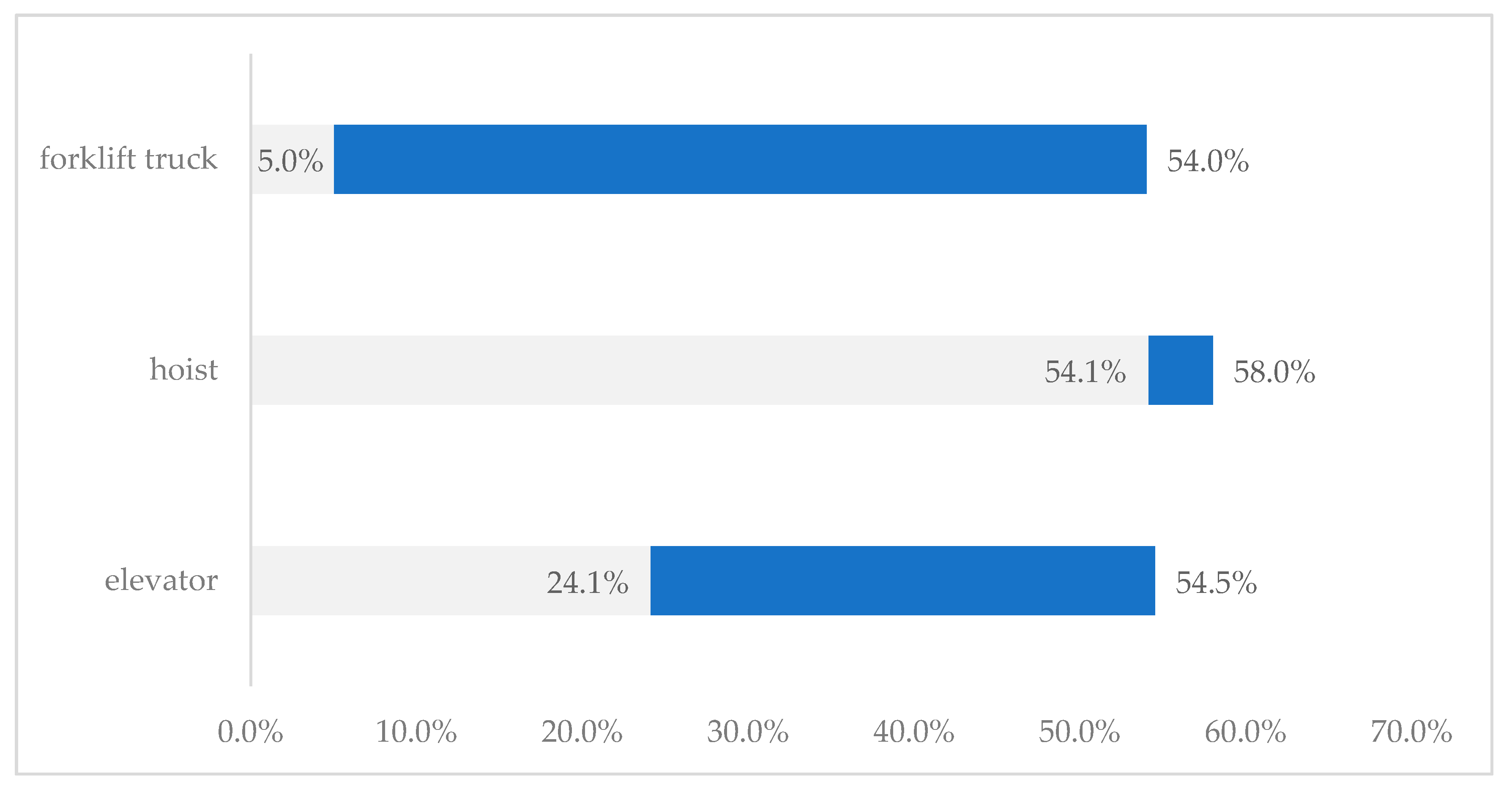
As aforementioned, the real elevator operation data shows that the energy conservation device had a high energy efficiency of 24.1–54.5% when using the proposed method in this study. According to the existing research [29,30], the energy-efficient rate of hoists is between 54.1% and 58%, and the rate of forklift trucks varies with fork speed, payload and setup system, reaching the maximum rate of 54%. Figure 12 shows the energy-efficient rate of different devices when the regenerative energy was applied, which presents that the energy-efficient rate of elevators is close to that of hoists and forklift trucks.
Each hoist or forklift truck requires their own energy conservation device, unlike that, our studied energy conservation device is designed for sharing within multiple elevators in the elevator group, which could also be used in a single elevator as a simplified version. This means that the expenditure on these devices could be reduced when achieving a given energy efficiency. Therefore, the studied method and design have a greater advantage than that applied in a single device.
5. Conclusion and Prospects
This paper shows an elevator group energy-efficient method based on a DC micro-grid, which is not only applicable to new-built elevators, but also to the reconstruction of existing elevator groups. The methodology, design and experiment were also investigated, showing the significance of energy efficiency.
The proposed method has a greater advantage than each energy storage device serving a single elevator. This method improves energy efficiency through shifting regenerative power from the elevator and reusing this power as a source to the elevator loading in the DC micro-grid. Theoretically, the required capacity of the energy storage device can be reduced with increasing number of elevators in the elevator group.
The results of the test experiment and actual operation show that the innovative approach could result in a high energy efficiency within 15.87–23.1% and 24.1–54.5%, respectively, which verifies that the proposed group method has a better performance.
The DC micro-grid of the elevator, as a part of building DC micro-grid, has expansibility. This can connect to another DC micro-grid in the building or directly access other loads, including the charging points of DC electric vehicles and a variety of DC distributed energy generation systems.
Author Contributions
Methodology, Y.Z., J.Y. and B.D.; Writing-Original Draft Preparation, Y.Z.; Investigation, Y.Z.; Funding Acquisition, Y.Z., F.Y. and J.Y.; Writing-Review & Editing, Z.Y.; Visualization, Z.Y.; Data curation, Z.Y.
Funding
This paper was funded by the National 13th Five-year Plan Key Project of Ministry of Science and Technology of China, grant number 2017YFB0903404, the Jiangsu Province Science and Technology Support Plan Project, grant number BE2014830, the Fundamental Research Funds for the Central Universities, grant number 102472015118, the China Postdoctoral Science Foundation Funded Project, grant number 2018M632162 and the Open Projects Fund of Key Laboratory of Shanghai Urban Renewal and Spatial Optimization Technology, grant number 201810101.
Acknowledgments
This research in experiment was supported by the ARTS (Zhongheng) Group Co., Ltd. And the authors are particularly grateful for the modification and improvement by Dr. Runqi Liang.
Conflicts of Interest
The authors declare no conflict of interest.
Nomenclature
| AC | Alternating Current |
| BAS | Building Automation System |
| DC | Direct Current |
| DCE | Double Car Elevator |
| IoT | Internet of Things |
| VFD | Variable Frequency Drive |
| VVVF | Variable Voltage and Variable Frequency |
References
- Barney, G.C.; Dos Santos, S.M. Elevator Traffic Analysis, Design and Control, 2nd ed.; Institution of Engineering and Technology: London, UK, 1985; ISBN 9780863410420. [Google Scholar]
- CIBSE Guide D: Transportation Systems in Buildings, 4th ed.; CIBSE Pub.: London, UK, 2010; ISBN 978-1906846169.
- Barney, G.C.; Al-Sharif, L. Elevator Traffic Handbook: Theory and Practice, 2nd ed.; Routledge Pub.: Abingdon, UK, 2015; 440p, ISBN 9781138852327. [Google Scholar]
- So, A.T.P.; Liu, S.K. An Overall Review of advanced elevator Technologies. Elevat. World 1996, 44, 96–101. [Google Scholar]
- Wang, D.H.; Cheng, K.W.E. General discussion on energy saving. In Proceedings of the 1st International Conference on Power Electronics Systems and Applications, Hong Kong, China, 9–11 November 2004; pp. 298–303. [Google Scholar]
- Ganga, D.; Ramachandran, V. IoT based Vibration Analytics of Electrical Machines. IEEE Internet Things J. 2018, 1, 1–12. [Google Scholar] [CrossRef]
- González, I.; Calderón, A.J.; Mejías, A.; Andújar, J.M. Novel Networked Remote Laboratory Architecture for Open Connectivity Based on PLC-OPC-LabVIEW-EJS Integration. Application in Remote Fuzzy Control and Sensors Data Acquisition. Sensors 2016, 16, 1822. [Google Scholar] [CrossRef] [PubMed]
- Kande, M.; Isaksson, A.J.; Thottappillil, R.; Taylor, N. Rotating Electrical Machine Condition Monitoring Automation—A Review. Machines 2017, 5, 24. [Google Scholar] [CrossRef]
- Saponara, S. Distributed Measuring System for Predictive Diagnosis of Uninterruptible Power Supplies in Safety-Critical Applications. Energies 2016, 9, 327. [Google Scholar] [CrossRef]
- Saponara, S.; Fanucci, L.; Bernardo, F.; Falciani, A. Predictive diagnosis of high-power transformer faults by networking vibration measuring nodes with integrated signal processing. IEEE Trans. Instrum. Meas. 2016, 65, 1749–1760. [Google Scholar] [CrossRef]
- Zhou, S.-Z.; Li, X.; Chen, G.; Hu, S. A Piecewise Control Strategy for a Bidirectional Series Resonant Converter. Electronics 2018, 7, 374. [Google Scholar] [CrossRef]
- Tukia, T.; Uimonen, S.; Siikonen, M.L.; Donghi, C.; Lehtonen, M. High-resolution modeling of elevator power consumption. J. Build. Eng. 2018, 18, 210–219. [Google Scholar] [CrossRef]
- Yu, L.; Zhou, J.; Mabu, S.; Shimada, K.; Hirasawa, K.; Markon, S. Multi-Car Elevator System using Genetic Network Programming. In Proceedings of the IEEE International Conference on Systems Man and Cybernetics, Tokyo, Japan, 20–22 August 2008. [Google Scholar]
- Ikeda, K.; Suzuki, H.; Markon, S.; Kita, H. Designing traffic-sensitive controllers for multi-car elevators through evolutionary multi-objective optimization. In Proceedings of the International Conference on Evolutionary Multi-Criterion Optimization, Matsushima, Japan, 5–8 March 2007; pp. 673–686. [Google Scholar]
- Yue, Y.T.; Wang, G.Z.; Kou, Z.Y. Study on Key Technologies of High-speed Elevators for Extra-high Buildings. Build. Electr. 2015, 5, 35–38. (In Chinese) [Google Scholar] [CrossRef]
- Ding, B.; Li, Q.C.; Zhang, Y.M.; Zhang, J.; Qi, W.G. Traffic mode prediction method for twin elevator group control system. J. Harbin Inst. Technol. 2013, 45, 79–83. (In Chinese) [Google Scholar] [CrossRef]
- Ding, B.; Zhang, Y.M.; Peng, X.Y.; Li, Q.C.; Tang, H.Y. A Hybrid Approach for the Analysis and Prediction of Elevator Passenger Flow in an Office Building. Autom. Constr. 2013, 35, 69–78. [Google Scholar] [CrossRef]
- Tang, H.Y.; Ding, B.; Qi, W.G. Study on optimal scheduling of multi control policy for elevator group. Trans. China Electrotech. Soc. 2007, 22, 179–183. (In Chinese) [Google Scholar]
- Bolat, B.; Altun, O.; Cortés, P. A particle swarm optimization algorithm for optimal car-call allocation in elevator group control systems. Appl. Soft Comput. 2013, 13, 2633–2642. [Google Scholar] [CrossRef] [Green Version]
- Cortés, P.; Onieva, L.; Muñuzuri, J.; Guadix, J. A viral system algorithm to optimize the car dispatching in elevator group control systems of tall buildings. Comput. Ind. Eng. 2013, 64, 403–411. [Google Scholar] [CrossRef] [Green Version]
- Zhang, J.L.; Zong, Q. Energy-saving scheduling optimization under up-peak traffic for group elevator system in building. Energy Build. 2013, 66, 495–504. [Google Scholar] [CrossRef]
- Kwon, O.; Lee, E.; Bahn, H. Sensor-aware elevator scheduling for smart building environments. Build. Environ. 2014, 72, 332–342. [Google Scholar] [CrossRef]
- Ahmed, S.S.; Iqbal, A.; Sarwar, R.; Salam, M.S. Modeling the energy consumption of a lift. Energy Build. 2014, 71, 61–67. [Google Scholar] [CrossRef]
- Liao, Y.J.; Liao, G.X.; Lo, S.M. Influencing factor analysis of ultra-tall building elevator evacuation. Procedia Eng. 2014, 71, 583–590. [Google Scholar] [CrossRef]
- Esteban, E.; Salgado, O.; Iturrospe, A.; Isasa, I. Model-based approach for elevator performance estimation. Mech. Syst. Signal Process. 2016, 68–69, 125–137. [Google Scholar] [CrossRef]
- Adak, M.F.; Duru, N.; Duru, H.T. Elevator simulator design and estimating energy consumption of an elevator system. Energy Build. 2013, 65, 272–280. [Google Scholar] [CrossRef]
- Tukia, T.; Uimonen, S.; Siikonen, M.L.; Hakala, H.; Donghi, C.; Lehtonen, M. Explicit method to predict annual elevator energy consumption in recurring passenger traffic conditions. J. Build. Eng. 2016, 8, 179–188. [Google Scholar] [CrossRef]
- Schofield, A.J.; Stonham, T.J.; Mehta, P.A. Automated people counting to aid lift control. Autom. Constr. 1997, 6, 437–445. [Google Scholar] [CrossRef]
- Lee, M.; Kim, T.; Jung, H.K.; Lee, U.K.; Cho, H.; Kang, K.I. Green construction hoist with customized energy regeneration system. Autom. Constr. 2014, 45, 66–71. [Google Scholar] [CrossRef]
- Minav, T.A.; Virtanen, A.; Laurila, L.; Pyrhönen, J. Storage of energy recovered from an industrial forklift. Autom. Constr. 2012, 22, 506–515. [Google Scholar] [CrossRef]
- Zhang, T.; Mabu, S.; Yu, L.; Zhou, J. Energy saving elevator group supervisory control system with Idle Cage Assignment using Genetic Network Programming. In Proceedings of the 2009 ICCAS-SICE, Fukuoka, Japan, 18–21 August 2009. [Google Scholar]
- Liu, Y.; Hu, Z.; Su, Q.; Huo, J. Energy Saving of Elevator Group Control Based on Optimal Zoning Strategy with Interfloor Traffic. In Proceedings of the 3rd International Conference on Information Management Innovation Management and Industrial Engineering, Kunming, China, 26–28 November 2010. [Google Scholar]
- Zhang, J.L.; Jie, T.; Zong, Q.; Li, J.F. Energy-saving scheduling strategy for elevator group control system based on ant colony optimization. In Proceedings of the 2010 IEEE Youth Conference on Information Computing and Telecommunications, Beijing, China, 28–30 November 2010. [Google Scholar]
- Marsong, S.; Plangklang, B. Implementation analysis of an elevator energy regenerative unit (EERU) for energy saving in a building. In Proceedings of the 2016 13th International Conference on Electrical Engineering/Electronics, Computer, Telecommunications and Information Technology (ECTI-CON), Chiang Mai, Thailand, 28 June–1 July 2016. [Google Scholar]
- D’Adamo, I. The Profitability of Residential Photovoltaic Systems. A New Scheme of Subsidies Based on the Price of CO2 in a Developed PV Market. Soc. Sci. 2018, 7, 148. [Google Scholar] [CrossRef]
- Wang, Y.H.; Li, Y.; Cao, Y.J.; Tan, Y.; Li, H.; Han, J.Y. Hybrid AC/DC microgrid architecture with comprehensive control strategy for energy management of smart building. Int. J. Electr. Power Energy Syst. 2018, 101, 151–161. [Google Scholar] [CrossRef]
- Tony, C.C.; Macarulla, A.M.; Kamara-Esteban, O.; Borges, C.E. Analysis and assessment of an off-grid services building through the usage of a DC photovoltaic microgrid. Sustain. Cities Soc. 2018, 38, 405–419. [Google Scholar] [CrossRef]
- Kubade, P.; Umathe, S.K. Enhancing an elevator efficiency by using supercapacitor. In Proceedings of the 2017 Third International Conference on Advances in Electrical, Electronics, Information, Communication and Bio-Informatics, Chennai, India, 27–28 February 2017. [Google Scholar]
- Mathew, S.; Mogre, P.; Chouthai, R.; Karandikar, P.B.; Kulkarni, N.R. Supercapacitor based energy recovery system for an elevator. In Proceedings of the 2017 International Conference on Advances in Computing, Communication and Control, Mumbai, India, 1–2 December 2017. [Google Scholar]
- Jabbour, N.; Mademlis, C. Supercapacitor-based energy recovery system with improved power control and energy management for elevator applications. IEEE Trans. Power Electron. 2017, 32, 9389–9399. [Google Scholar] [CrossRef]
- Liu, H.P.; Liu, K.; Sun, B.N. Analysis of energy management strategy for energy-storage type elevator based on supercapacitor. In Proceedings of the 2017 11th IEEE International Conference on Compatibility, Power Electronics and Power Engineering, Cadiz, Spain, 4–6 April 2017. [Google Scholar]
- Braslavsky, I.; Plotnikov, I.; Ishmatov, Z.; Polunin, F. The estimation of technical and economic efficiency of using the supercapacitors in the hoisting applications. In Proceedings of the 2014 International Symposium on Power Electronics, Electrical Drives, Automation and Motion, Ischia, Italy, 18–20 June 2014. [Google Scholar]
- Li, Z.; Ruan, Y. A Novel Energy Saving Control System for Elevator Based on, Supercapacitor Bank Using Fuzzy Logic. In Proceedings of the 2008 International Conference on Electrical Machines and Systems, Wuhan, China, 17–20 October 2008. [Google Scholar]
- Kafalis, K.; Karlis, A.D. Supercapacitors based energy saving mode of electromechanical elevator’s operation. In Proceedings of the 2016 XXII International Conference on Electrical Machines, Lausanne, Switzerland, 4–7 September 2016. [Google Scholar]
- Huang, B.C. Elevator energy-efficient control system of shared DC bus. Build. Electr. 2007, 7, 8–10. (In Chinese) [Google Scholar] [CrossRef]
- Zhang, Y.M.; Fu, W.D.; Ding, B.; Liu, Q. Electrical energy conservation based on DC distribution and DC microgrid. Trans. China Electrotech. Soc. 2015, 30, 389–397. (In Chinese) [Google Scholar] [CrossRef]
- Zhang, Y.M.; Yan, Z.; Li, L.; Yao, J.W. A Hybrid Building Power Distribution System in Consideration of Supply and Demand-Side: A Short Overview and a Case Study. Energies 2018, 11, 3082. [Google Scholar] [CrossRef]
- Cha, H.J.; Won, D.J.; Kim, S.H.; Chung, I.Y.; Han, B.-M. Multi-Agent System-Based Microgrid Operation Strategy for Demand Response. Energies 2015, 8, 14272–14286. [Google Scholar] [CrossRef] [Green Version]
- Huang, W.T.; Chen, T.H.; Chen, H.T.; Yang, J.S.; Lian, K.L.; Chang, Y.R.; Lee, Y.D.; Ho, Y.H. A Two-stage Optimal Network Reconfiguration Approach for Minimizing Energy Loss of Distribution Networks Using Particle Swarm Optimization Algorithm. Energies 2015, 8, 13894–13910. [Google Scholar] [CrossRef] [Green Version]
- Elena Dragomir, O.; Dragomir, F.; Stefan, V.; Minca, E. Adaptive Neuro-Fuzzy Inference Systems as a Strategy for Predicting and Controling the Energy Produced from Renewable Sources. Energies 2015, 8, 13047–13061. [Google Scholar] [CrossRef] [Green Version]
- Sanseverino, E.R.; Di Silvestre, M.L.; Badalamenti, R.; Nguyen, N.Q.; Guerrero, J.M.; Meng, L. Optimal Power Flow in Islanded Microgrids Using a Simple Distributed Algorithm. Energies 2015, 8, 11493–11514. [Google Scholar] [CrossRef] [Green Version]
- Thangavelu, S.R.; Nutkani, I.U.; Hwee, C.M.; Myat, A.; Khambadkone, A. Integrated Electrical and Thermal Grid Facility—Testing of Future Microgrid Technologies. Energies 2015, 8, 10082–10105. [Google Scholar] [CrossRef]
- Yao, J.; Zhang, Y.; Yan, Z.; Li, L. A Group Approach of Smart Hybrid Poles with Renewable Energy, Street Lighting and EV Charging Based on DC Micro-Grid. Energies 2018, 11, 3445. [Google Scholar] [CrossRef]
Figure 1.
The inverter main circuit and energy storage for the energy-efficient method.

Figure 2.
Elevator DC micro-grid power dispatching energy-efficient method diagram.

Figure 3.
Voltage characteristics of the DC link in the elevator AC-DC-AC converter.
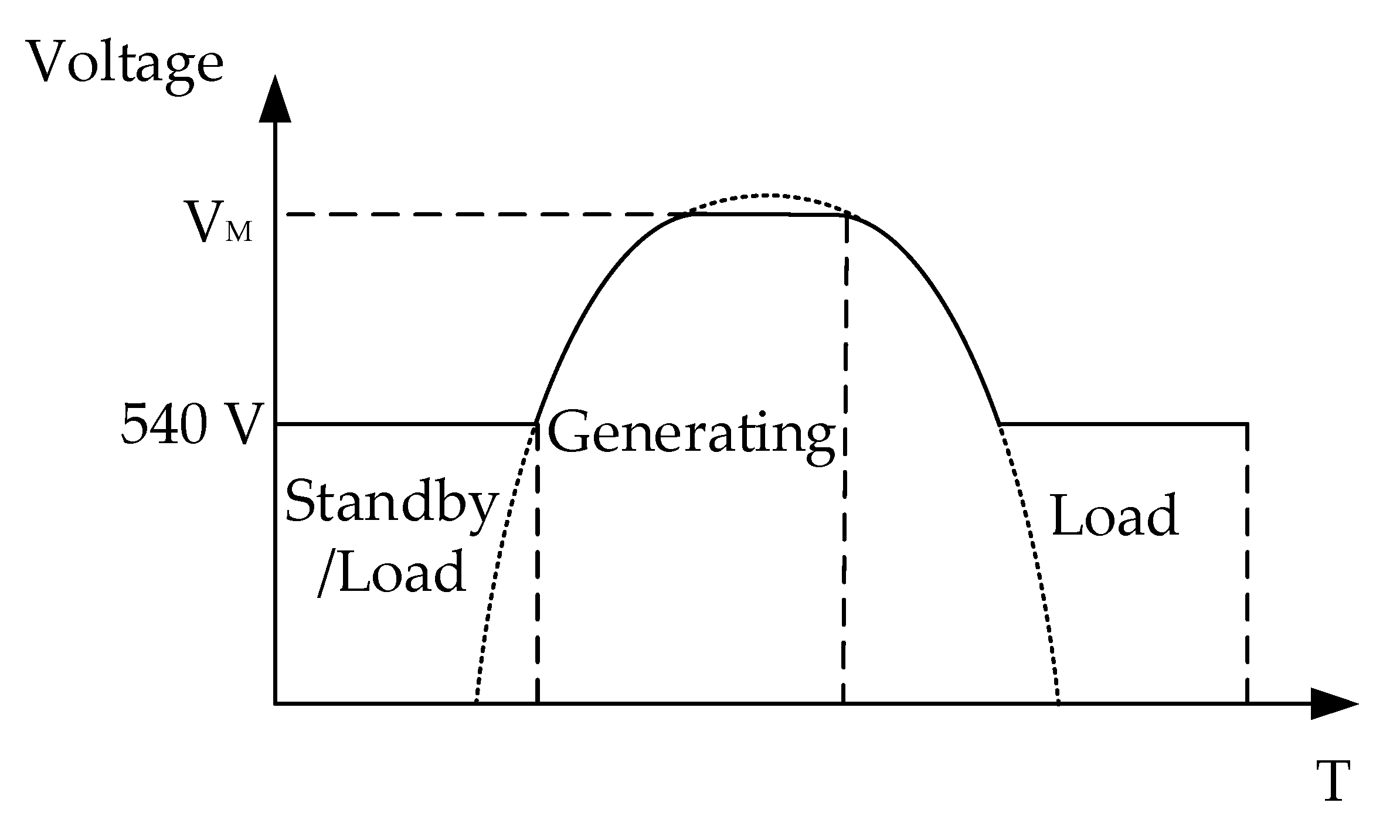
Figure 4.
Voltage characteristic of a supercapacitor charging and discharging.

Figure 5.
Zhongheng Design Center Building.
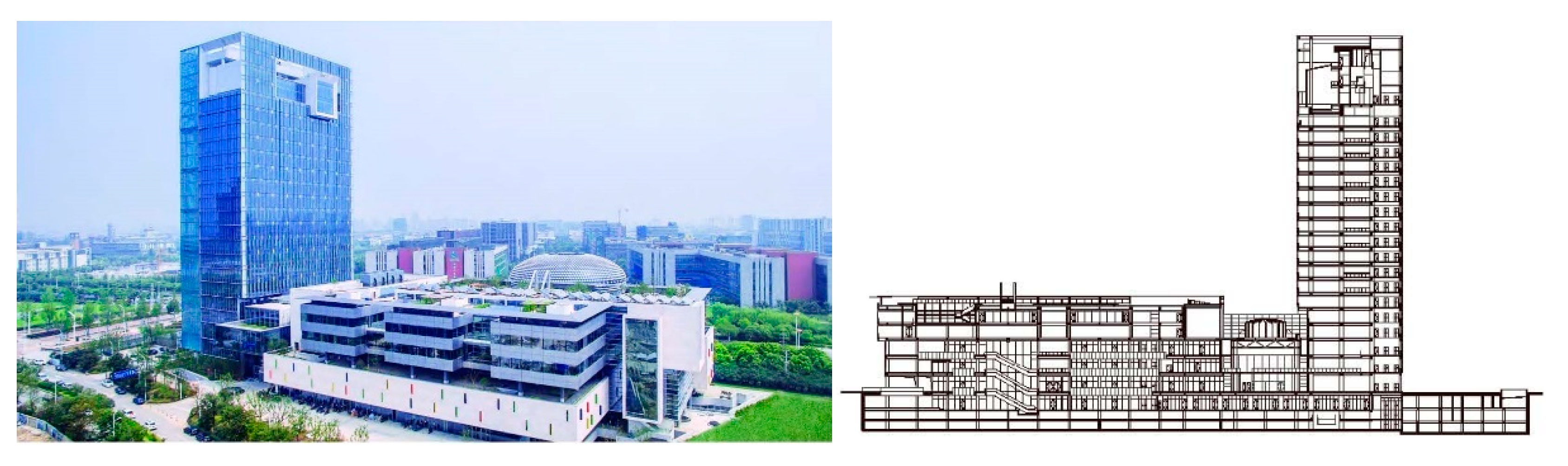
Figure 6.
The elevator traction machine, power supply and control cabinet.

Figure 7.
The design of the elevator DC micro-grid [47].
Figure 7.
The design of the elevator DC micro-grid [47].
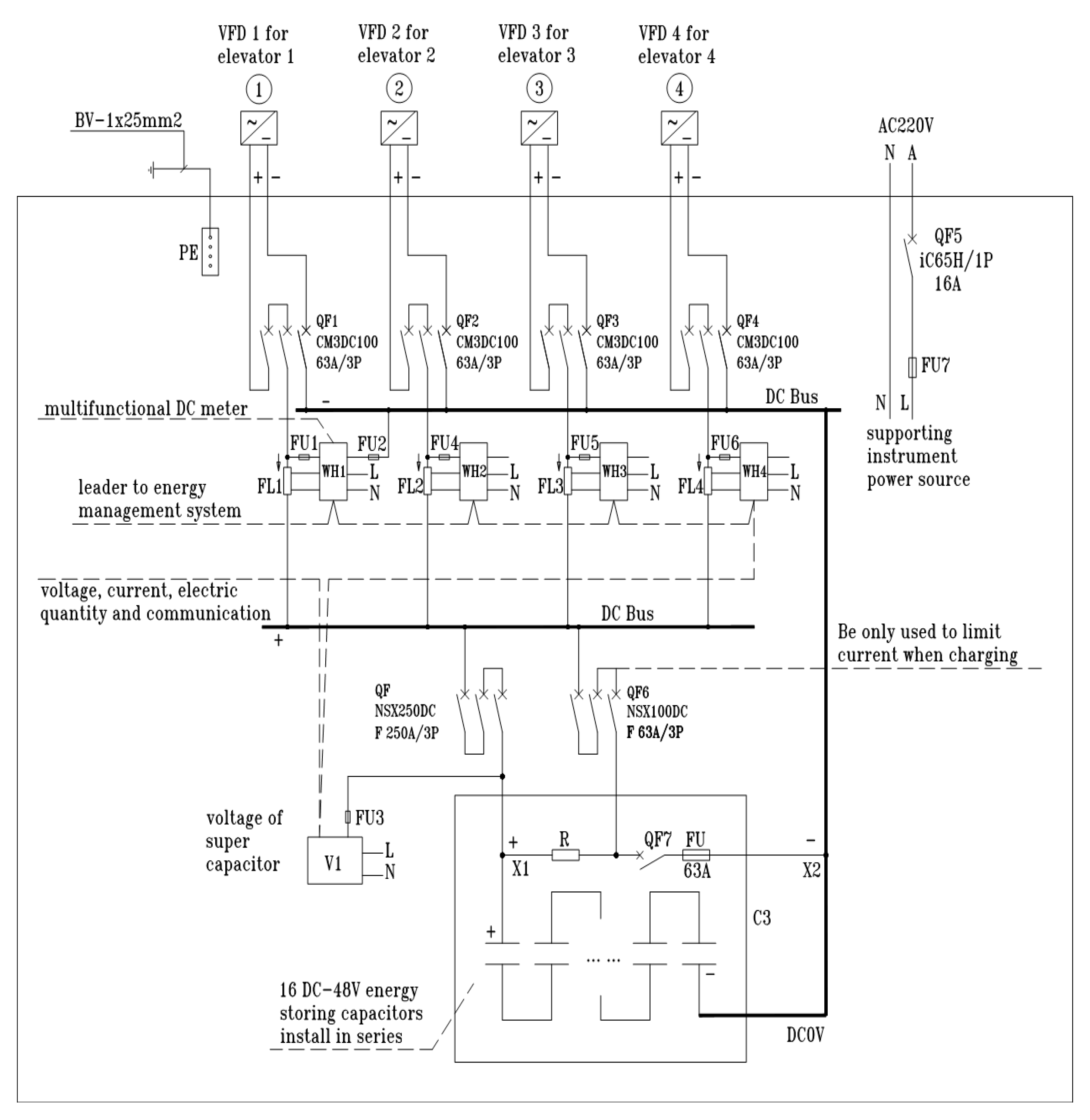
Figure 8.
The input and output power of the supercapacitor at the upgoing state [47].
Figure 8.
The input and output power of the supercapacitor at the upgoing state [47].

Figure 9.
The energy consumption and energy-efficient rate in the experiment [47].
Figure 9.
The energy consumption and energy-efficient rate in the experiment [47].

Figure 10.
The accumulated energy consumption (kWh) and energy-efficient rate (%) of elevator group from 1 July 2016 to 11 July 2016.
Figure 10.
The accumulated energy consumption (kWh) and energy-efficient rate (%) of elevator group from 1 July 2016 to 11 July 2016.
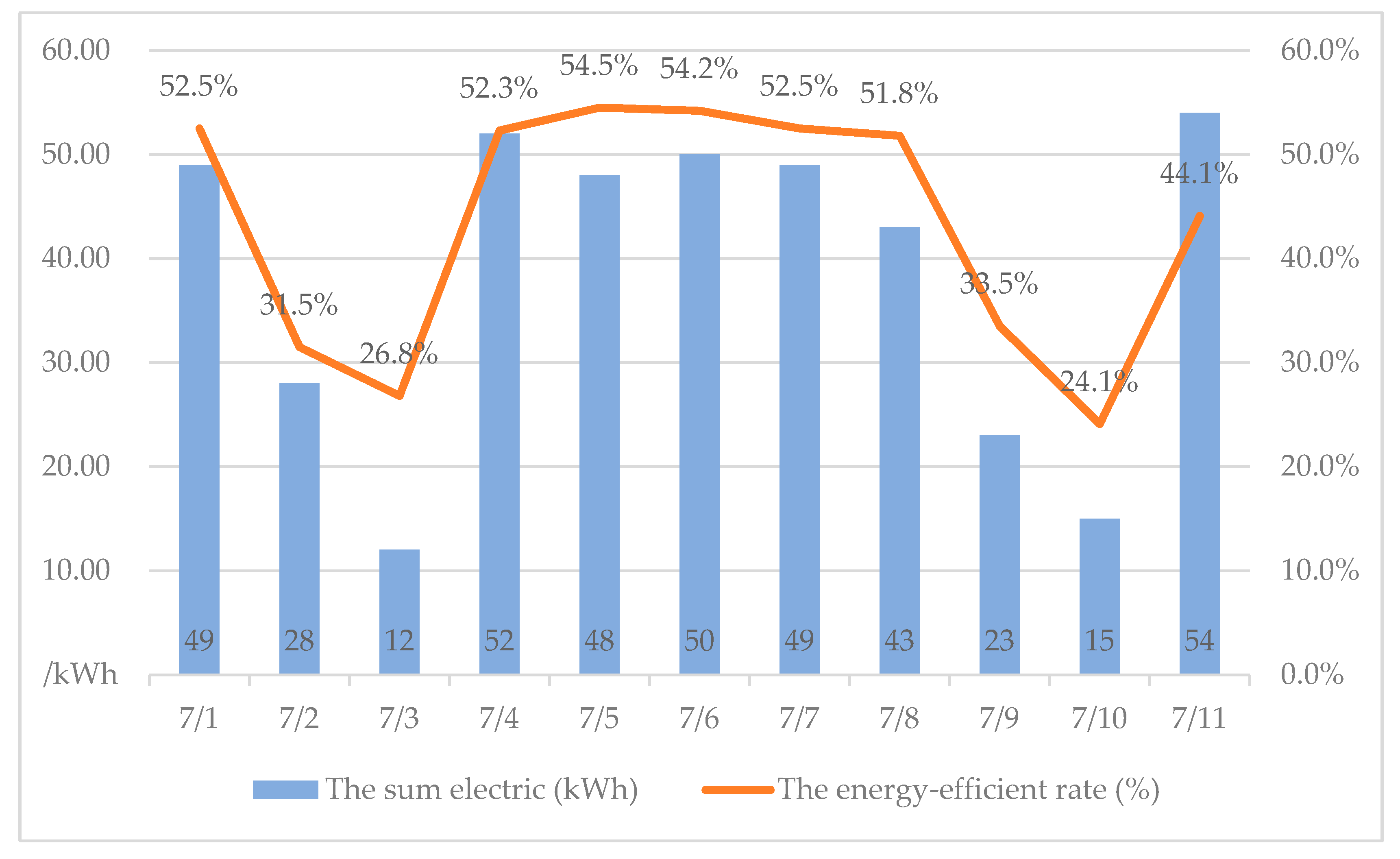
Figure 11.
The relation schema of the accumulated electric energy consumption (kWh) and the energy-efficient rate (%).
Figure 11.
The relation schema of the accumulated electric energy consumption (kWh) and the energy-efficient rate (%).
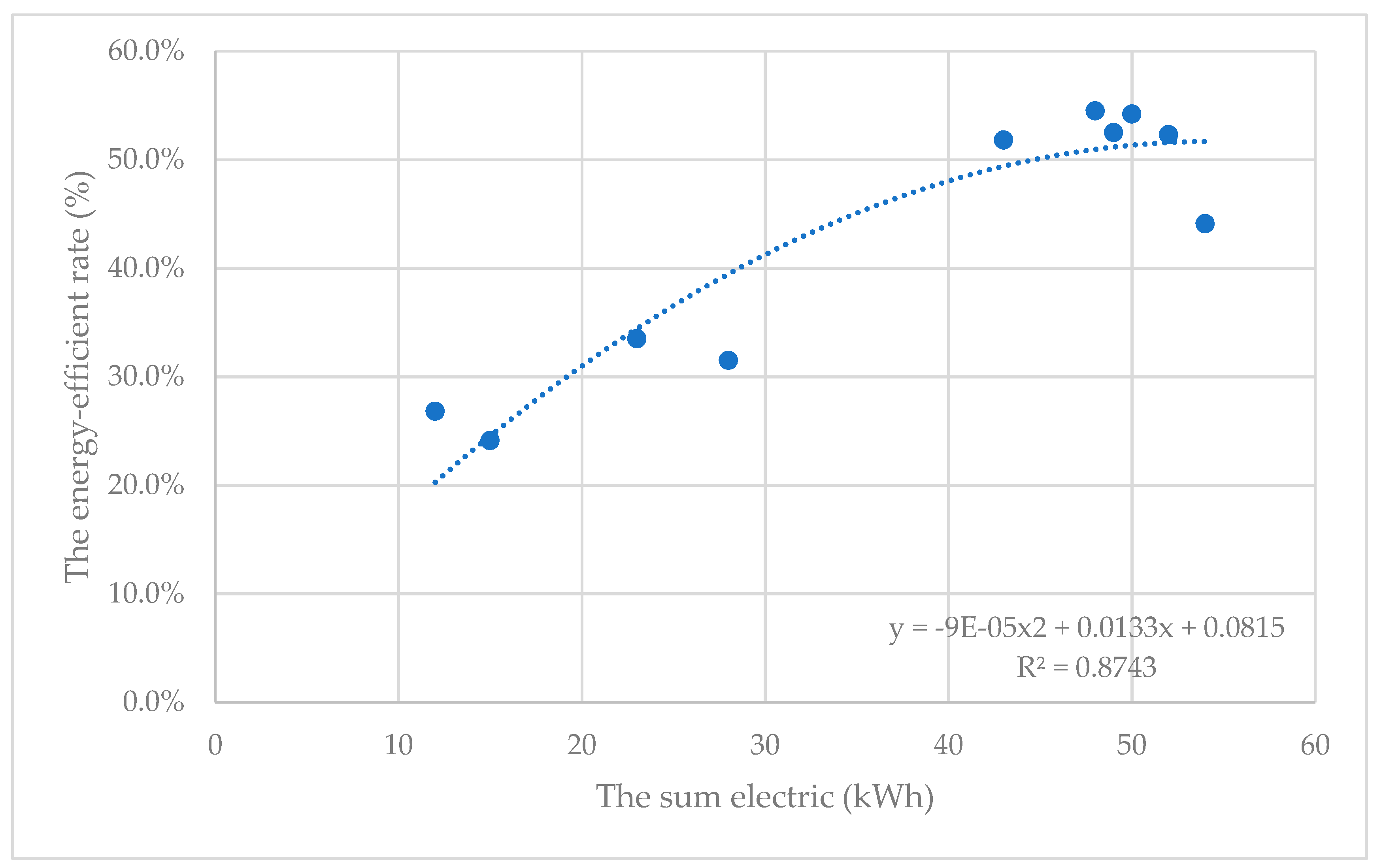
Figure 12.
The range of energy-efficient rates of supercapacitor in different devices.
© 2018 by the authors. Licensee MDPI, Basel, Switzerland. This article is an open access article distributed under the terms and conditions of the Creative Commons Attribution (CC BY) license (http://creativecommons.org/licenses/by/4.0/).
Share and Cite
MDPI and ACS Style
Zhang, Y.; Yan, Z.; Yuan, F.; Yao, J.; Ding, B. A Novel Reconstruction Approach to Elevator Energy Conservation Based on a DC Micro-Grid in High-Rise Buildings. Energies 2019, 12, 33. https://doi.org/10.3390/en12010033
AMA Style
Zhang Y, Yan Z, Yuan F, Yao J, Ding B. A Novel Reconstruction Approach to Elevator Energy Conservation Based on a DC Micro-Grid in High-Rise Buildings. Energies. 2019; 12(1):33. https://doi.org/10.3390/en12010033
Chicago/Turabian StyleZhang, Yongming, Zhe Yan, Feng Yuan, Jiawei Yao, and Bao Ding. 2019. "A Novel Reconstruction Approach to Elevator Energy Conservation Based on a DC Micro-Grid in High-Rise Buildings" Energies 12, no. 1: 33. https://doi.org/10.3390/en12010033
Note that from the first issue of 2016, this journal uses article numbers instead of page numbers. See further details here.