On Speed Control of a Permanent Magnet Synchronous Motor with Current Predictive Compensation

1
School of Electrical Engineering, Southwest Jiaotong University, Chendu 610031, Sichuan, China
2
Department of Manufacturing and Transportation, Hangzhou Wanxiang Polytechnic College, Hangzhou 310023, Zhejiang, China
*
Author to whom correspondence should be addressed.
Energies 2019, 12(1), 65; https://doi.org/10.3390/en12010065
Submission received: 4 November 2018
/
Revised: 25 November 2018
/
Accepted: 10 December 2018
/
Published: 26 December 2018
(This article belongs to the Special Issue Permanent Magnet Synchronous Machines)
Abstract
:In this study, a current model predictive controller (MPC) is designed for a permanent magnet synchronous motor (PMSM) where the speed of the motor can be regulated precisely. First, the mathematical model, the specifications, and the drive topology of the PMSM are introduced, followed by an elaboration of the design of the MPC. The MPC is then used to predict the current in a discrete-time calculation. The phase current at the next sampling step can be estimated to compensate the current errors, thereby modifying the three-phase currents of the motor. Next, Simulink modeling of the MPC algorithm is given, with three-phase current waveforms compared when the motor is operated under the designed MPC and a traditional vector control for PMSM. Finally, the speed responses are measured when the motor is controlled by traditional control methods and the MPC approach under varied speed references and loads. In comparison with traditional controllers, both the simulation and the experimental results suggest that the MPC for the PMSM can improve the speed-tracking performance of the motor and that this motor has a fast speed response and small steady-state errors under the rated load.
1. Introduction
Permanent magnet synchronous motor (PMSM) technology is widely explored and employed in industrial equipment, aerospace aircraft, domestic appliances, and electric vehicles. The motor takes advantage of high working efficiency, high power density, highly accurate position tracking, and low power factor, as compared to induction motors [1]. One popular application of PMSM is the surface-mounted permanent magnet (PM) motor, with embedded PM motors already widely used in industry. The direct-axis inductance and quadrature-axis inductance of the surface-mounted PM motor are equal because this motor has identical air gaps around the stator [2]. The identical inductance values enhance the performance of the power converter for the motor as a load. Consequently, control of the motor becomes easier, since the motor is at a constant load. As of now, field-oriented control (FOC) is widely employed for PMSM [3]. After sampling the phase currents of the motor, the controller of the motor converts three-phase current signals to two orthogonal values via Clark and Parker transformations. The alternating-current motor can be controlled like a direct-current motor because the amplitude of phase voltage or current can be directly regulated to control the motor, thus improving its performance and simplifying the control [4]. Generally, the current loop regulation for PMSM includes hysteresis control and pulse width modulation (PWM) [5]. Vector control further simplifies the control by using seven voltage vectors to directly drive the motor without current modulation, improving its dynamic response [6]. Space vector pulse width modulation (SVPWM) is becoming increasingly popular for the motor. Moreover, the mechanical performance of the motor can be enhanced by SVPWM in combination with flux-weakening modulation when the motor is operated in high-speed applications. Also, some papers have investigated direct torque control (DTC) to improve the performance of the motor. DTC can directly govern the torque of the motor by observing flux linkage and speed. As reported in the literature [7], DTC is employed to reduce the torque ripples of the motor by an optimized duty cycle. This control method has also been investigated to address the fault tolerance, maximum torque outputs, and evaluation of power factors for PMSM [8,9,10]. In one study in particular, a predictive DTC has been developed to propose a fault-tolerance function for PMSM [10]. The performance and dynamic responses of the motor can be further modified.
Recently, model predictive control (MPC) as an advanced control method has become more attractive for the control of PMSM and has been strongly developed in the last three decades. For power electronics development, MPC can merge cascaded control loops into one loop for power converters in the initial exploration algorithm, especially for multivariable systems, to tackle parameter varieties [11]. An MPC consists mainly of three parts: a cost function, a predictive model, and a model of the load. By minimizing the cost function, the motor will reach the desired behavior defined by the function that compares the output of the predictive model with a reference [5]. Weighting factors play an important role for fast responses and the stability of the control system [12]. Two main branches of MPC are finite control set MPC (FCS-MPC) and continuous control set MPC (CCS-MPC) [13,14]; CCS-MPC calculates a continuous control solution and outputs a desired voltage in the power converter through a modulator with a fixed switching frequency. In addition, modified generalized predictive control (GPC) and explicit MPC (EMPC) are popular and increase some scholars’ interest [15,16]; FCS-MPC discretizes the signal to formulate the MPC algorithm without external modulation and can be sorted in two types, namely, optimal switching vector MPC (OSV-MPC) and optimal switching sequence MPC (OSS-MPC) [17,18]. OSV-MPC computes predictive values for the power converter only via an enumerated searching algorithm, making this MPC very intuitive. Only one voltage vector is employed in the entire switching period. This drawback of this MPC is avoided by OSS-MPC, which produces a limited number of possible switching sequences in a working period. In general, all MPC methods heretofore mentioned are time-consuming for microprocessors. CCS-MPC outweighs FCS-MPC in the aspect of computational cost, as the former predicts the output value and optimizes it offline. Under this condition, CCS-MPC can be used on a long predictive horizon, which can stabilize the whole system because more steps need to be predicted by the controller [19]. By contrast, FCS-MPC methods are usually adopted in short predictive horizons. Therefore, the key factors of MPC are the selection of a cost function, the design of the weighting factor, the reduction of the computational cost, and the predictive horizon extension. In recent studies, some practical MPCs of PMSM have been developed to simplify the control, to save computing time, to eliminate harmonic currents, and to reduce torque ripples [20,21,22,23]. Designing a practical, stable MPC quickly and applying the controller on a PMSM to replace traditional methods is meaningful for industrial applications.
In this study, an MPC is introduced and designed for a PMSM, with phase currents regulated by a simple predictive control, and a computation period reduced for microchips. Speed control of the motor by using the MPC is carried out under varied loads. The performance of MPC is compared with those of FOC, SVPWM, and DTC. In Section 2 of this paper, the mathematical model of the PMSM is elaborated. In Section 3, a Simulink model is built. Experiments are carried out in Section 4. Conclusions are presented in Section 5. First, the model of a surface-mounted PMSM is introduced as well as the basic control method mentioned, particularly the influence of the calculation step time for three-phase bridge topology. Then, the principles of MPC are given, followed by a predictive model of the inverter and the model of the PMSM. Finally, an MPC for the PMSM is designed, built, and programmed, with simulations and experimental results showing the improvement of the performance of the motor. Phase currents of the motor can be regulated accurately under limited calculation steps. The whole performance of the motor is improved by MPC with a fast response and smaller response errors.
2. Mathematical Model of the PMSM
2.1. PMSM Model
The voltage equation for the PMSM under Cartesian coordinates can be expressed by Equation (1), neglecting local magnetic circuit saturation, eddy losses, and hysteresis losses.
The equation for flux linkage of the motor can be expressed by
where is the flux linkage of the three windings. and are voltages, resistances, and currents of the motor, respectively. is the three-phase inductance, and is the three-phase angle.
where are mutual inductances, and are inductance leakages. The torque of the motor can be calculated as
are pole pairs of the motor. The dynamic behavior of the motor can be expressed by
where is the rotating inertia of the motor, B is the damping coefficient, and is the loading torque. is the angular speed of the motor. Two classical current regulations, hysteresis comparator and PWM regulation, are popular for the current loop of PMSM and they are able to regulate the phase current of PMSMs. The main specifications of the motor are listed in Table 1.
2.2. Drive Topology
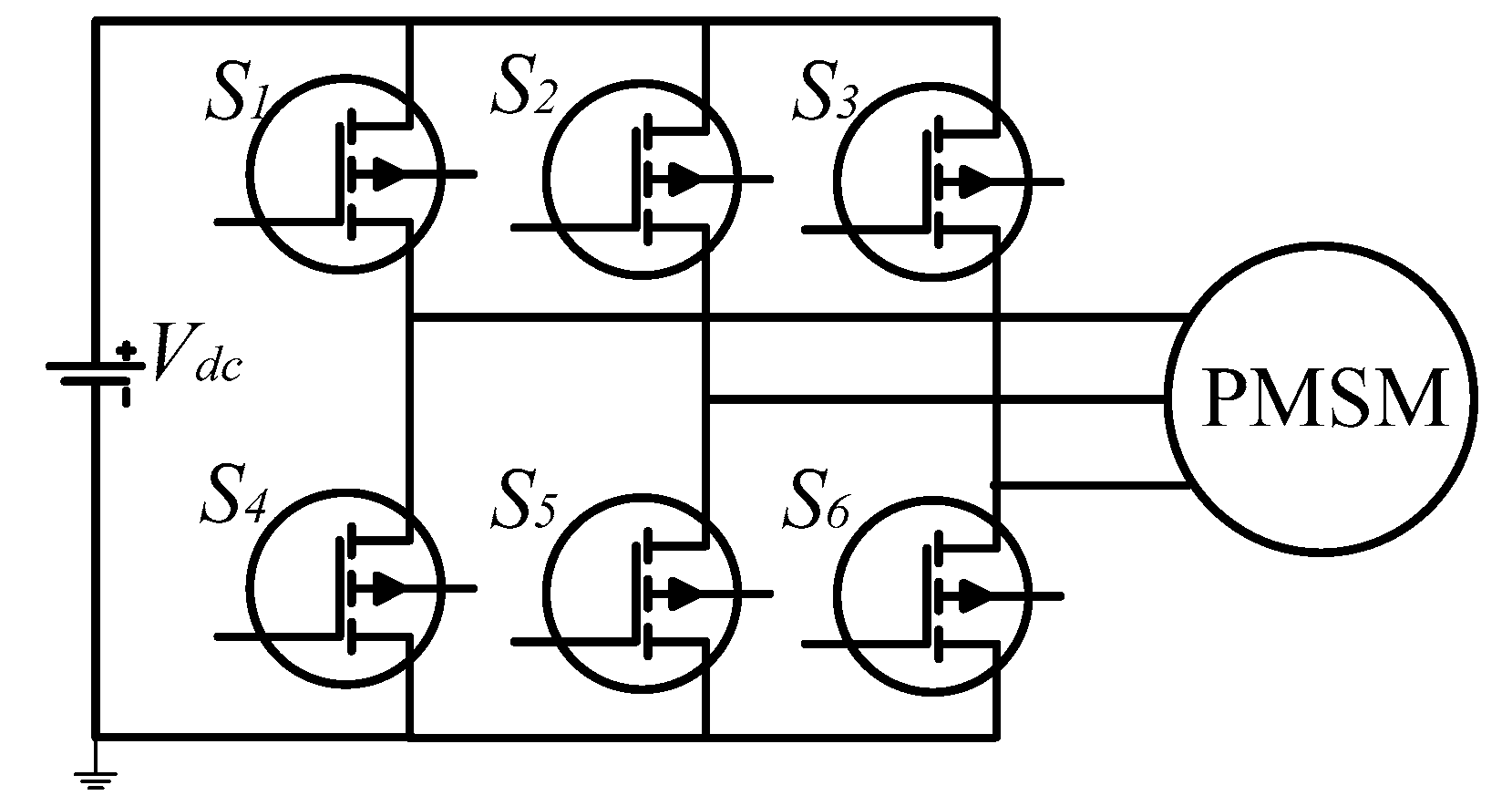
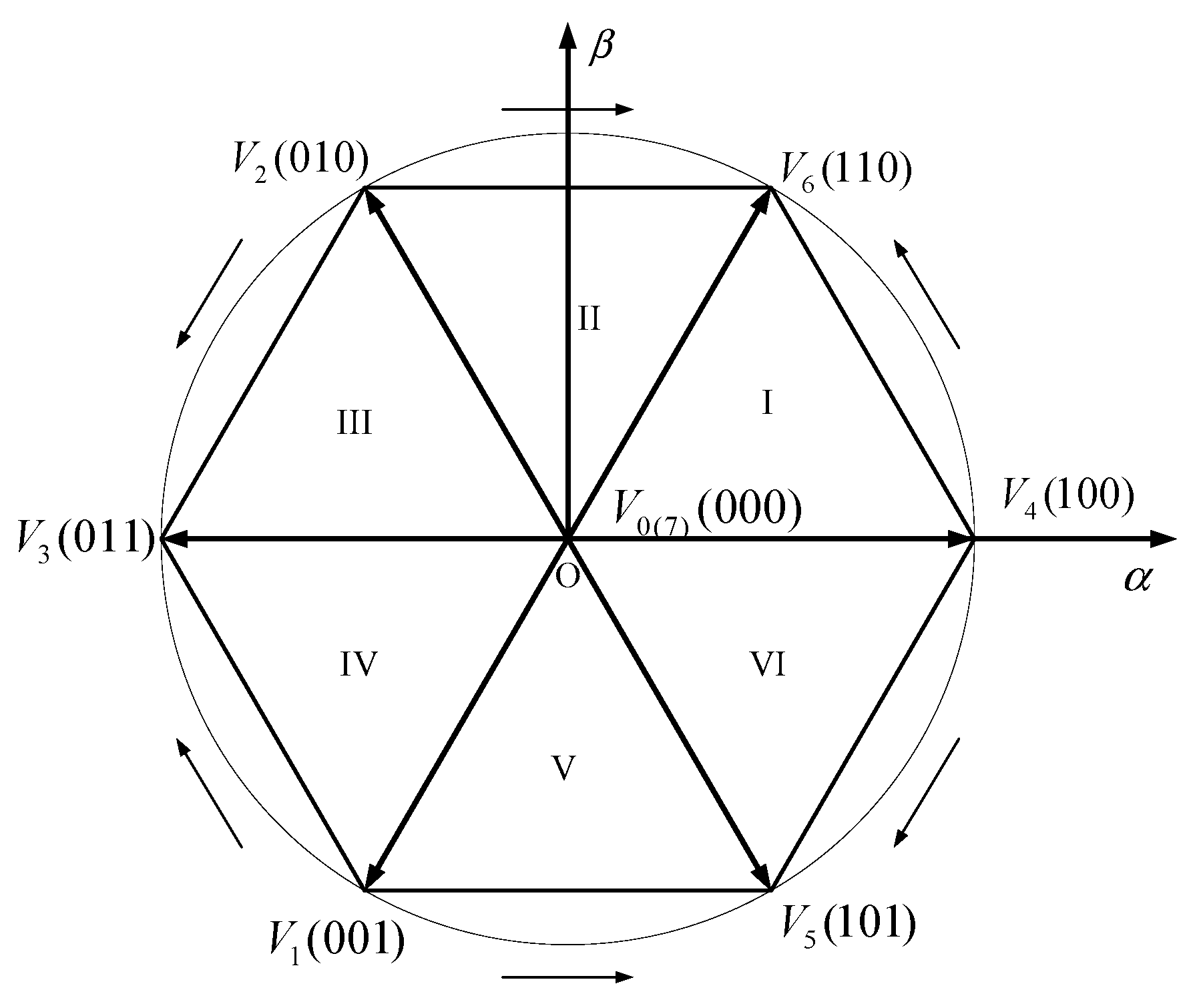
The three-phase inverter topology for PMSM is shown in Figure 1. Six metal-oxide semiconductor field-effect transistors (MOSFETs) and their states are given and indicated as S1–S6. For one bridge, S1 and S4 cannot switch on simultaneously in case of a short circuit between Vdc and the ground. Therefore, when S1 switches on, S4 will switch off and vice versa. For three-phase alternative current motors, six MOSFETs construct eight switching modes, i.e., V1–V6, as shown in Figure 2. The eight vectors divide the vector plane into six sections for the motor.
2.3. Model Predictive Control
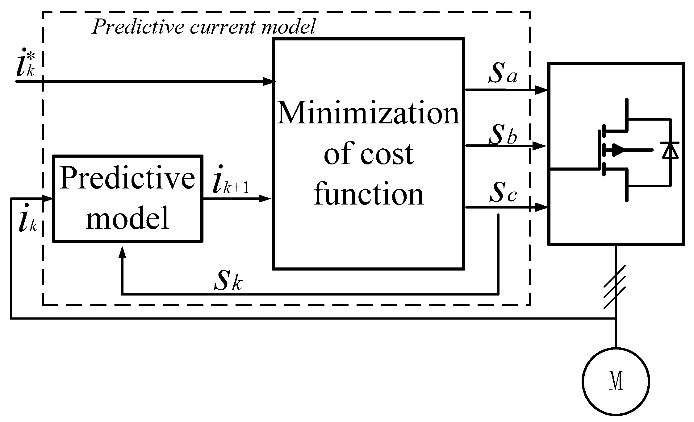
An MPC consists mainly of three parts: (1) a cost function, (2) a predictive model of the inverter, and (3) a model of the load. For the control of the PMSM, the load is the PMSM. The entire control scheme is shown in Figure 3. A predictive current is obtained by a predictive model that includes parts 2 and 3. The predictive current and the current reference are the inputs of part 1. If a static power converter can be controlled by a set of switching states within a finite number, these states can be predicted by an MPC according to criteria that can estimate the predictive values. This criterion is called the cost function. This function is used to predict the future variables for the system or the switching states of the inverter. The state that minimizes the cost function is usually the criterion.
In this study, a current MPC is employed to control a PMSM. As a load, the model of the PMSM has been given. However, the discrete-time model of the motor is needed, and this model will be an important part of the predictive model. In addition, this predictive model should take the model of the inverter into consideration as well. The states of the switches can be expressed by Equation (11):
where and the voltage vector generated by the inverter is formulated as Equation (12).
Consequently, the load voltage vector can be calculated by the switching states.
According to the voltage vector of Equation (12), the current vectors for the PMSM can be expressed as Equation (14), and the back electromagnetic force s Equation (15).
The load current dynamic is calculated in Equation (16):
This function can be expressed by two equations after Clark and Parker transformation:
The discretized dynamic functions of the predictive model from Equations (17) and (18) can be expressed as
The discrete currents derived from Equations (19) and (20) according to the dynamic functions are
The cost function is used to select the voltage vector for the PMSM. The voltage vectors will be applied to the inverter so that the phase currents of the PMSM will reach the expected current references in the next sampling time after minimizing the cost function. The consequence is that the predictive current will be applied to the motor, and it will be operated according to the references. For current prediction of the PMSM, the cost function is given as Equation (23). The flow chart of the current predictive control is shown in Figure 4. Assuming that the initial value of the cost function is infinite, when the temporary variable j changes from 0 to 7, the states of the MOSFETs will be determined. First, the voltage vector can be obtained according to Equation (13). Then, the predicted current in the d-q axis can be calculated from Equations (22) and (23), respectively. Finally, according to the cost function, as given in Equation (23), the states of the MOSFETs will be obtained if the temporary variable j = 7. Otherwise, the program will jump to Equation (13). The corresponding control algorithm code is shown in the Appendix A.
3. Simulink Modeling of the MPC Algorithm
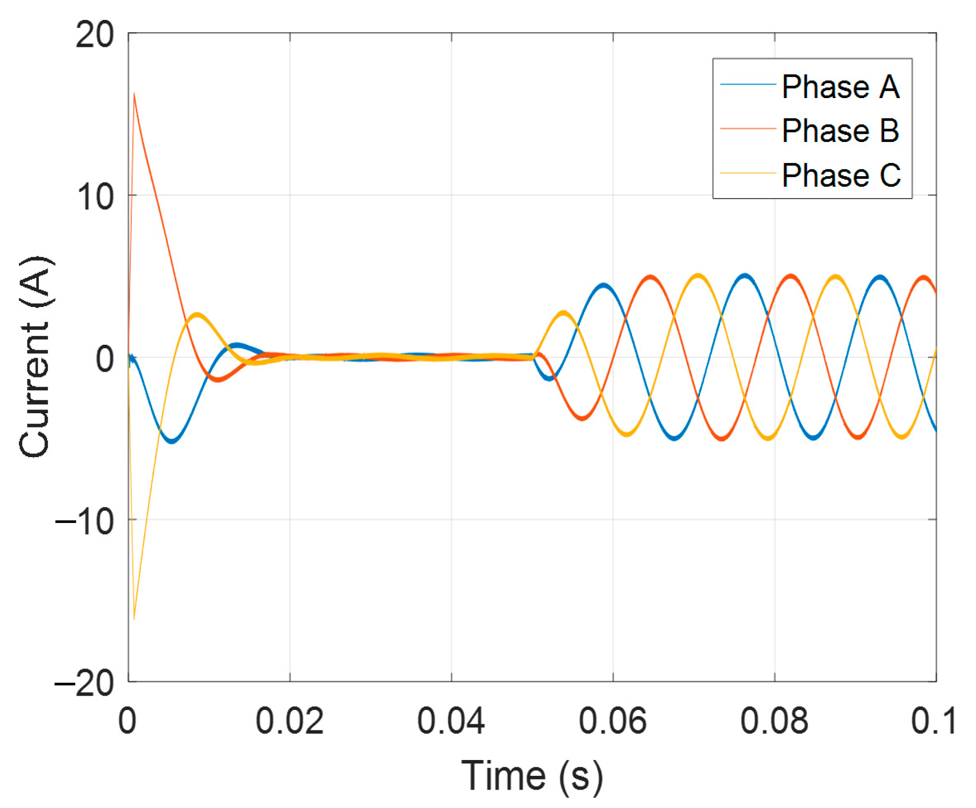
Simulations for an MPC of a PMSM are designed as shown in Figure 5. The whole operation time is 0.1 s. The reference speed changes from 500 rpm to 1000 rpm at 0.03 s, and the load varies from 5 Nm to 8 Nm at 0.07 s.
Three-phase currents are shown in Figure 6. Also, simulations are carried out when the motor is controlled by an SVPWM controller. Three-phase currents are obtained in Figure 7. and are also obtained. Compared with the three-phase currents under the two controllers, the inverter outputs nonsinusoidal currents for the MPC but totally sinusoidal waves for the SVPWM. The amplitudes of the currents from the SVPWM method change dramatically when the speed reference changes and the load varies.
4. Experimental Verification
Experimental Setup
The experimental setup is established by employing a dSPACE DS1104 card, which can be regarded as a microprocessor. The microprocessor is the controller of the whole system after the proposed algorithm is programmed and downloaded. The experimental hardware is shown in Figure 8, including power suppliers, a computer, a dSPACE control card, three highly accurate current sensors, a driver of the three-phase PMSM, and the motor. The entire control part of the PMSM is built using MATLAB/Simulink software, and the designed program can be debugged into the dSPACE card. An encoder interface of the card is employed to obtain the angles and the speeds of the rotor, and six analog-to-digital converters are used to sample the phase currents and voltages of the motor for the controller.
Three-phase currents of the motor under steady state with no load and in loaded state at the speed of 500 rpm are shown in Figure 9a,b. When the motor works with no load, the amplitude of the three-phase current is 0.3 A, and the currents are nearly sinusoidal. When a rated load of 8 Nm is produced for the motor at this speed, it can be seen from Figure 9b that the three-phase currents of the motor with the MPC controller are increased accordingly, with slight current deformation. This deformation begins mainly at the interchange section between the top half of the current and the bottom half; the dead time of MOSFETs could be the cause. In Figure 10, the reference speed increases to 1000 rpm, the initial currents are shown when the motor starts, and the load of 5 Nm is carried on at 0.05 s. The motor performs well at the beginning and in the loaded states.
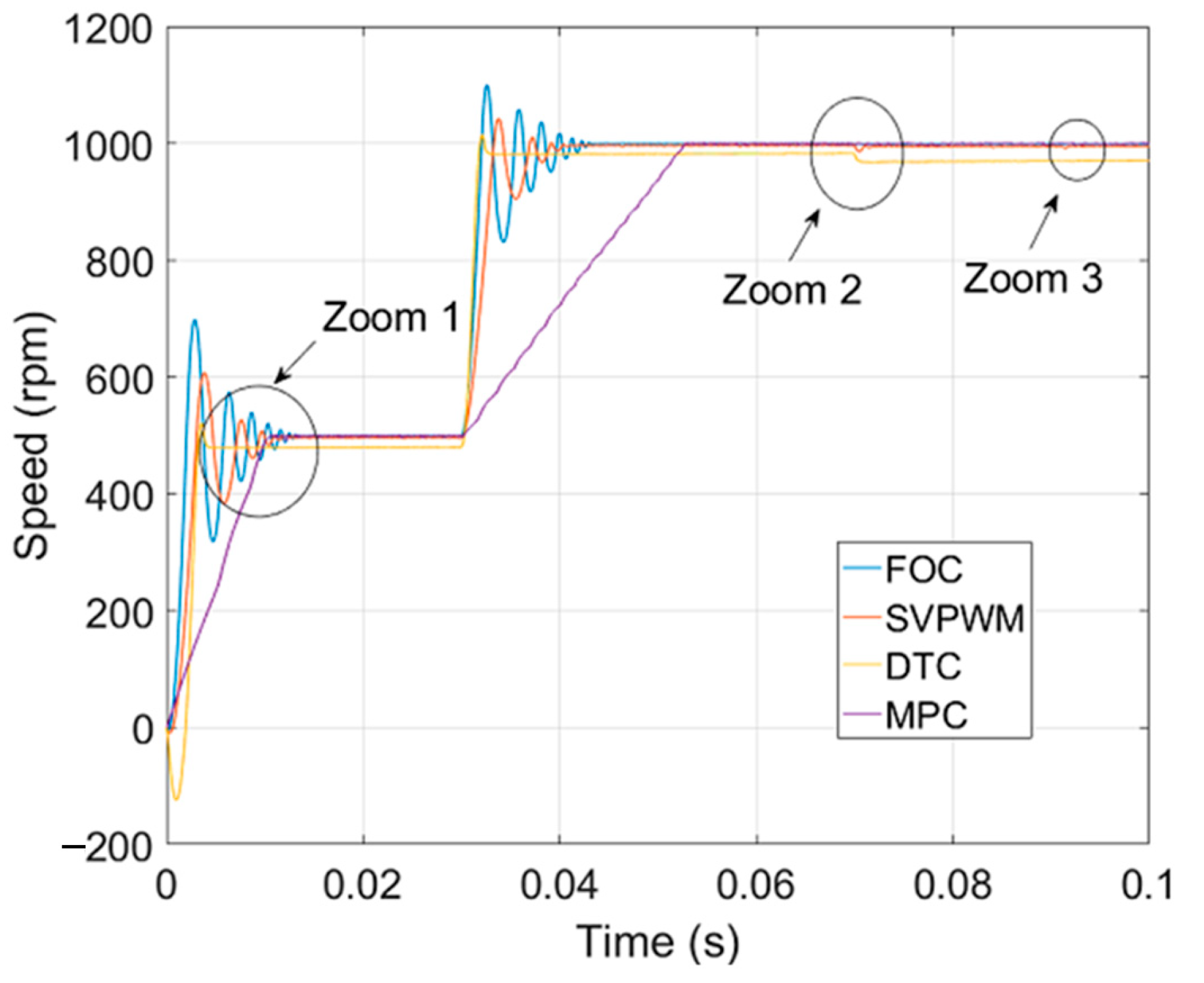
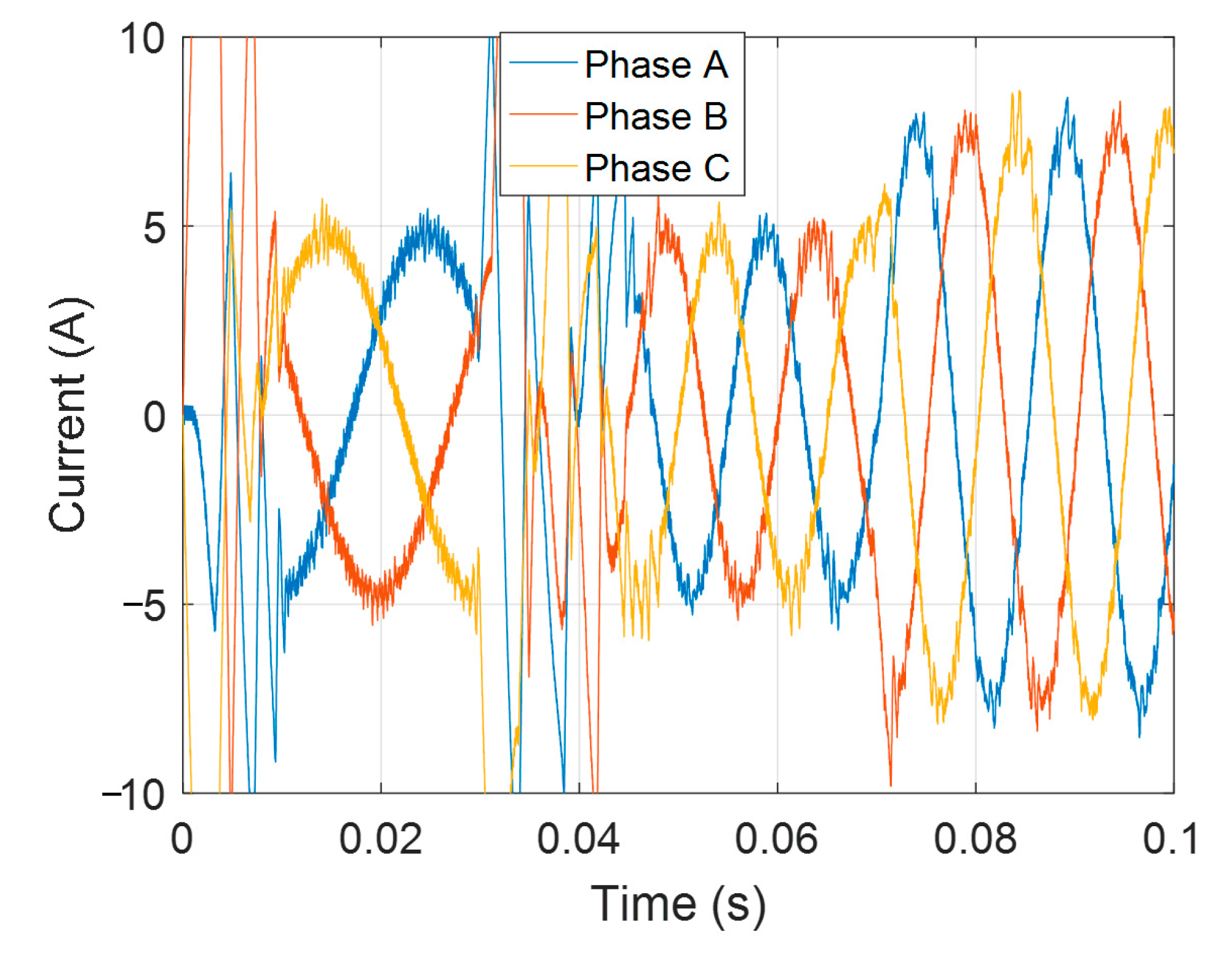
The speed control of the motor with the current MPC is shown in Figure 11, compared with classic control methods. The speed reference is 500 rpm under the load of 5 Nm, increasing to 1000 rpm at 0.03 s. The load increases from 5 Nm to 8 Nm at 0.07 s. There is no overshoot if the motor is governed by the MPC. The speed cannot fully reach the reference when the motor enters a steady state via the controllers of FOC, SVPWM, and DTC. Three details are shown in Figure 12, including the motor start (zoom 1), the loading variation (zoom 2), and the steady-state errors (zoom 3). The three-phase measured currents of the motor are shown in Figure 13. These details show that the dynamic responses under MPC outweigh those of other controllers, with fewer overshoots and small steady-state errors. The MPC system is not vulnerable to varied loads or to the parameter change of the control system. In addition to the MPC, other controllers cannot avoid overshoot and vibration when the motor starts. Although the DTC has less rising time, the steady-state error from this controller is obvious. In Figure 12b, the controllers of both the FOC and the MPC are stable, with the loading torque varying from 1 Nm to 2 Nm. The steady-state errors are shown in Figure 12c. The FOC can curb the steady error at the lowest scope. However, this method has an obvious overshoot. The steady errors can be limited at 5 rpm by using MPC and other control methods, suggesting higher steady errors that exceed 5 rpm. This shows that the performance of the designed MPC outweighs that of other controllers under identical conditions.
Figure 14 shows the speed response of the motor under different speed references. The speed reference starts at 100 rpm in the beginning and increases to 500 rpm at 0.02 s and 1000 rpm at 0.05 s. The entire speed response is shown in Figure 14a. The details of the speed variations at each step are shown in Figure 14b–d. There are a few overshoots within 1% at the stepping times. Speed steady-state errors could be on the rise with the increase of the speed reference. However, the speed steady-state errors can be limited to 0.5 rpm according to the experimental results.
5. Conclusions
In this study, a current MPC of a PMSM was investigated. The mathematical model of the motor and the Simulink modeling of the MPC method are given. Both the simulation and experimental results suggest that the designed MPC is feasible. For practical application, the main programmed algorithm is also given. The speed responses show that the MPC performs better than traditional controllers, as supported by the simulation and experimental results. MPC is shown to possess fast-tracking capability and small steady errors in speed regulation, and the speed reference has a lower overshoot under varied loads. The speed responses could be limited to 0.5 rpm, with experimental results validated under different speed references. The experimental results proved the feasibility and effectiveness of the designed MPC. This control method could be a promising candidate to control the PMSM in the future.
Author Contributions
M.T. developed the analysis, hardware design, and measurement. He also conducted the simulation. S.Z. was responsible for the background theory. He also provided guidance and supervision.
Funding
The authors gratefully acknowledge the support by the government of Hang Zhou city (grant code 2017JD60) and Zhejiang Provincial Education Department funding with code YB201705.
Conflicts of Interest
The authors declare no conflict of interest.
Appendix A
The main function of the code is to determine the states of MOSFET according to the cost function g. According to the topology in Figure 1, the entire states of all MOSFETs can be determined if states S1, S2, and S3 are obtained. States S4, S5, and S6 are correspondingly opposite to the three former states. The control program corresponding to Figure 4 is shown below.
function Smin = MPC[wr,id,iq,theta]
s = [0 0 0; 0 0 1; 0 1 0; 0 1 1;1 0 0; 1 0 1; 1 1 0; 1 1 1]
gm = zeros(8,1);
s1 = s2 = s3 = s4 = s5 = s6 = s6 = s7 = 0;
for i = 1:8
sa = s(i,1); sb = s(i,2); sc = s(i,3);
Vinva = (Vdc*(2*Sa − b − Sc))/3;
Vinvb = (Vdc*(2*Sb − Sa − Sc))/3;
Vinvc = (Vdc*(2*Sc − Sb − Sa))/3;
vsq = (2/3)*((Vinva*cos((Wr*t + theta))) + (Vinvb*cos((Wr*t) + theta + (4*pi/3))) + (Vinvc*cos((Wr*t) + theta + (2*pi/3))));
vsd = (2/3)*((Vinva*sin((Wr*t + teta))) + (Vinvb*sin((Wr*t) + theta + (4*pi/3))) + (Vinvc*sin((Wr*t) + theta + (2*pi/3))));
iq1 = iq + Ts*[vsq − R*iq − L*wr*id − phi*wr]/L;
id1 = id + Ts*[vsd − R*id + L*wr*Iq]/L
g = abs(idr − id1) + abs(iqr − iq1);
if(g < gm)
i_min = i;
g_min = g;
end
end
v = v(i_min);
iq = iq1;
id = id1;
s = s(:,i_min);
References
- Krishnan, R. Permanent Magnet Synchronous and Brushless DC Motor Drives; CRC Press/Taylor & Francis: Boca Raton, FL, USA, 2010. [Google Scholar]
- Hanselman, D.C. Brushless Permanent-Magnet Motor Design; McGraw-Hill: New York, NY, USA, 1994. [Google Scholar]
- Abu-Rub, H.; Iqbal, A.; Guzinski, J. High Performance Control of AC Drives with MATLAB/Simulink Models; John Wiley & Sons: Hoboken, NJ, USA, 2012. [Google Scholar]
- Quang, N.P.; Dittrich, J. Vector Control of Three-Phase AC Machines System Development in the Practice; Springer: Berlin/Heidelberg, Germany, 2015. [Google Scholar]
- Rodriguez, J.; Pontt, J.; Silva, C.A.; Correa, P.; Lezana, P.; Cortes, P.; Ammann, U. Predictive Current Control of a Voltage Source Inverter. IEEE Trans. Ind. Electron. 2007, 54, 495–503. [Google Scholar] [CrossRef]
- Bida, V.M.; Samokhvalov, D.V.; Al-Mahturi, F.S. PMSM vector control techniques—A survey. In Proceedings of the IEEE Conference of Russian Young Researchers in Electrical and Electronic Engineering (EIConRus), Moscow, Russia, 29 January–1 February 2018; pp. 577–581. [Google Scholar] [CrossRef]
- Mohan, D.; Zhang, X.; Foo, G.H.B. A Simple Duty Cycle Control Strategy to Reduce Torque Ripples and Improve Low-Speed Performance of a Three-Level Inverter Fed DTC IPMSM Drive. IEEE Trans. Ind. Electron. 2017, 64, 2709–2721. [Google Scholar] [CrossRef]
- Shinohara, A.; Inoue, Y.; Morimoto, S.; Sanada, M. Maximum Torque Per Ampere Control in Stator Flux Linkage Synchronous Frame for DTC-Based PMSM Drives Without Using q-Axis Inductance. IEEE Trans. Ind. Appl. 2017, 53, 3663–3672. [Google Scholar] [CrossRef]
- Xia, C.; Wang, S.; Gu, X.; Yan, Y.; Shi, T. Direct Torque Control for VSI-PMSM Using Vector Evaluation Factor Table. IEEE Trans. Ind. Electron. 2016, 63, 4571–4583. [Google Scholar] [CrossRef]
- Zhou, Y.; Chen, G. Predictive DTC Strategy with Fault-Tolerant Function for Six-Phase and Three-Phase PMSM Series-Connected Drive System. IEEE Trans. Ind. Electron. 2018, 65, 9101–9112. [Google Scholar] [CrossRef]
- Wang, S.; Xu, D.D.; Li, C. Dynamic control set-model predictive control for field-oriented control of VSI-PMSM. IEEE Appl. Power Electron. Conf. Expos. 2018, 2630–2636. [Google Scholar] [CrossRef]
- Caseiro, L.M.A.; Mendes, A.M.S.; Cruz, S.M.A. Dynamically Weighted Optimal Switching Vector Model Predictive Control of Power Converters. IEEE Trans. Ind. Electron. 2018. [Google Scholar] [CrossRef]
- Siami, M.; Khaburi, D.A.; Rivera, M.; Rodríguez, J. A Computationally Efficient Lookup Table Based FCS-MPC for PMSM Drives Fed by Matrix Converters. IEEE Trans. Ind. Electron. 2017, 64, 7645–7654. [Google Scholar] [CrossRef]
- Ahmed, A.A.; Koh, B.K.; Lee, Y.I. A Comparison of Finite Control Set and Continuous Control Set Model Predictive Control Schemes for Speed Control of Induction Motors. IEEE Trans. Ind. Inform. 2018, 14, 1334–1346. [Google Scholar] [CrossRef]
- Shoukry, Y.; El-Kharashi, M.W.; Hammad, S. MPC-On-Chip: An Embedded GPC Coprocessor for Automotive Active Suspension Systems. IEEE Embed. Syst. Lett. 2010, 2, 31–34. [Google Scholar] [CrossRef]
- Pejcic, I.; Korda, M.; Jones, C.N. Control of nonlinear systems with explicit-MPC-like controllers. In Proceedings of the IEEE 56th Annual Conference on Decision and Control (CDC), Melbourne, VIC, Australia, 12–15 December 2017; pp. 4970–4975. [Google Scholar] [CrossRef]
- Vazquez, S.; Aguilera, R.P.; Pablo Acuna, J.P.; Agelidis, V.G. Model Predictive Control for Single-Phase NPC Converters Based on Optimal Switching Sequences. IEEE Trans. Ind. Electron. 2016, 63, 7533–7543. [Google Scholar] [CrossRef]
- Kakosimos, P.; Abu-Rub, H. Predictive Speed Control with Short Prediction Horizon for Permanent Magnet Synchronous Motor Drives. IEEE Trans. Power Electron. 2018, 33, 2740–2750. [Google Scholar] [CrossRef]
- Rubino, S.; Bojoi, R.; Odhano, S.A.; Zanchetta, P. Model predictive direct flux vector control of multi three-phase induction motor drives. IEEE Trans. Ind. Appl. 2018. [Google Scholar] [CrossRef]
- Zhang, Y.; Huang, L.; Xu, D.; Liu, J.; Jin, J. Performance evaluation of two-vector-based model predictive current control of PMSM drives. Chin. J. Electr. Eng. 2018, 4, 65–81. [Google Scholar] [CrossRef]
- Zhang, X.; He, Y. Direct Voltage-Selection Based Model Predictive Direct Speed Control for PMSM Drives without Weighting Factor. IEEE Trans. Power Electron. 2018. [Google Scholar] [CrossRef]
- Luo, Y.; Liu, C. Elimination of Harmonic Currents Using a Reference Voltage Vector Based-Model Predictive Control for a Six-Phase PMSM Motor. IEEE Trans. Power Electron. 2018. [Google Scholar] [CrossRef]
- Zhou, Z.; Xia, C.; Yan, Y.; Wang, Z.; Shi, T. Torque Ripple Minimization of Predictive Torque Control for PMSM With Extended Control Set. IEEE Trans. Ind. Electron. 2017, 24, 6930–6939. [Google Scholar] [CrossRef]
Figure 1.
Inverter topology for the permanent magnet synchronous motor (PMSM).

Figure 2.
Voltage vectors for the PMSM.

Figure 3.
Scheme of current model predictive controller (MPC) for the PMSM.

Figure 4.
Main flow chart of the controller for the MPC.

Figure 5.
MPC blocks for the PMSM.

Figure 6.
Three-phase currents of the motor. (a) The currents under MPC, (b) the currents under vector control.
Figure 6.
Three-phase currents of the motor. (a) The currents under MPC, (b) the currents under vector control.

Figure 7.
The currents of the motor after coordination transformation from three phases to the d-q axis. (a) of the motor and (b) of the motor.
Figure 7.
The currents of the motor after coordination transformation from three phases to the d-q axis. (a) of the motor and (b) of the motor.

Figure 8.
Experimental setup of the PMSM control system.

Figure 9.
Three-phase currents of the motor. (a) The currents when the motor is operated with a rated load and (b) with no load.
Figure 9.
Three-phase currents of the motor. (a) The currents when the motor is operated with a rated load and (b) with no load.

Figure 10.
Sstart of three-phase currents and the currents with load of 5 Nm.

Figure 11.
Speed responses of the motor under different controllers. FOC: field-oriented control, SVPWM: space vector pulse width modulation, DTC: direct torque control.
Figure 11.
Speed responses of the motor under different controllers. FOC: field-oriented control, SVPWM: space vector pulse width modulation, DTC: direct torque control.

Figure 12.
Details of the speed responses with zoomed parts: (a) zoom 1, (b) zoom 2, and (c) zoom 3.
Figure 12.
Details of the speed responses with zoomed parts: (a) zoom 1, (b) zoom 2, and (c) zoom 3.


Figure 13.
Three-phase measured currents of the motor.

Figure 14.
Speed responses under different speed references. (a) Complete graph of the speeds changing from 100 rpm to 500 rpm and finally to 1000 rpm. (b) Speed changes from 0 rpm to 100 rpm. (c) Speed changes from 100 rpm to 500 rpm. (d) Speed changes from 500 rpm to 1000 rpm.
Figure 14.
Speed responses under different speed references. (a) Complete graph of the speeds changing from 100 rpm to 500 rpm and finally to 1000 rpm. (b) Speed changes from 0 rpm to 100 rpm. (c) Speed changes from 100 rpm to 500 rpm. (d) Speed changes from 500 rpm to 1000 rpm.


Table 1.
Main specifications of the motor.
| Specifications | Quantity (SI) |
|---|---|
| Rated power | 500 W |
| Rated current | 8 A |
| Pole number (p) | 8 |
| Length of the stator (l) | 350 mm |
| Number of turns of each coil | 60 |
| Width of the mover plate (w) | 16 mm |
| Height of the mover plate (h) | 16 mm |
| Width of the coil area (c) | 10 mm |
© 2018 by the authors. Licensee MDPI, Basel, Switzerland. This article is an open access article distributed under the terms and conditions of the Creative Commons Attribution (CC BY) license (http://creativecommons.org/licenses/by/4.0/).
Share and Cite
MDPI and ACS Style
Tang, M.; Zhuang, S. On Speed Control of a Permanent Magnet Synchronous Motor with Current Predictive Compensation. Energies 2019, 12, 65. https://doi.org/10.3390/en12010065
AMA Style
Tang M, Zhuang S. On Speed Control of a Permanent Magnet Synchronous Motor with Current Predictive Compensation. Energies. 2019; 12(1):65. https://doi.org/10.3390/en12010065
Chicago/Turabian StyleTang, Meiling, and Shengxian Zhuang. 2019. "On Speed Control of a Permanent Magnet Synchronous Motor with Current Predictive Compensation" Energies 12, no. 1: 65. https://doi.org/10.3390/en12010065
Note that from the first issue of 2016, this journal uses article numbers instead of page numbers. See further details here.