Modified State-of-Charge Balancing Control of Modular Multilevel Converter with Integrated Battery Energy Storage System


State Key Laboratory of Advanced Electromagnetic Engineering and Technology, School of Electrical and Electronic Engineering, Huazhong University of Science and Technology, Wuhan 430074, China
*
Author to whom correspondence should be addressed.
Energies 2019, 12(1), 96; https://doi.org/10.3390/en12010096
Submission received: 22 November 2018
/
Revised: 21 December 2018
/
Accepted: 24 December 2018
/
Published: 28 December 2018
(This article belongs to the Special Issue Multilevel Converters: Analysis, Modulation, Topologies, and Applications)
Abstract
:Modular multilevel converter with integrated battery energy storage system (MMC-BESS) has been proposed for energy storage requirements in high-voltage applications. The state-of-charge (SOC) equilibrium of batteries is essential for BESS to guarantee the capacity utilization. However, submodule voltage regulation can lead to over-modulation of individual submodules, which will limit the efficiency of SOC balancing control. Focusing on this problem, a modified SOC balancing control method with high efficiency is proposed in this paper. The tolerance for battery power unbalance is defined to quantize the convergence of SOC balancing control. Both the DC component and AC component are considered while regulating submodule voltage. The linear programming method is introduced to realize the maximum tolerance for battery power unbalance in different operation modes. Based on the analysis, by choosing appropriate submodule voltage regulation method, the efficiency of SOC balancing control is improved greatly. In addition, the SOC controller is also optimally designed to avoid over-modulation of submodules. Finally, the detailed simulation and experiment results verify the effectiveness of the analysis and proposed control strategy.
1. Introduction
In recent years, renewable resources are becoming more and more important, but they have great impact on grid due to their stochastic nature, reducing the voltage and frequency stability [1,2]. Battery energy storage system (BESS) is necessary and effective in these applications to improve the stability [3]. As the interface between batteries and grid, many researches focus on medium and high-voltage power conversion system (PCS).
Due to the advantages in medium and high-voltage applications, modular multilevel converters (MMC) has been used in BESS (MMC-BESS). Batteries can be directly connected with the DC bus in a centralized manner [4]. However, the series connection of massive batteries reduces the reliability and increases the complexity of energy management. In [5,6,7], batteries are integrated into submodules of MMC, constituting a modularized and distributed PCS. Compared with the centralized structure, the reliability and flexibility of distributed structure are greatly improved. Hence, it is more applicable to medium and high-voltage applications [8]. Most importantly, MMC-BESS is not only a pure PCS, but also a three-port converter. As an example, Figure 1 is the structure diagram of wind energy system. By integrating batteries into MMC, the original PCS is eliminated, which simplifies the whole configuration and lowers the costs. In addition, BESS can coordinate the operation of AC and DC side while transferring power among them [9]. Figure 1b is the topology of MMC-BESS, consisting of three phases, each with two arms. In submodule A, batteries are directly connected with submodules [10,11]. However, low-frequency current ripple can flow into batteries, which leads to additional heat generation and temperature rise of batteries. That will accelerate the degradation of batteries, resulting in significant reduction of battery life span [12,13]. Then a DC/DC converter (isolated or non-isolated) is used to filter the low-frequency current in submodule B [14,15,16]. The main advantages of non-isolated DC/DC are the simple structure and low cost. The isolated DC/DC can achieve the electrical isolation between batteries and MMC, which is utilized to meet some special requirements of batteries, such as grounding. At the same time, the DC/DC converter offers an additional control degree of freedom (DOF). Therefore, the capacitor voltage can be directly controlled by the DC/DC converter with traditional dual closed-loop control structure. Compared with the methods based on traditional MMC [17,18], the capacitor voltage balancing control is greatly simplified, and this paper also prefers this control structure.
For the massive submodules of MMC-BESS, the state-of charge (SOC) of each submodule will inevitably be different. The capacity utilization of the whole BESS is limited by the submodules with highest or lowest SOC due to the over-charge or over-discharge of them. Therefore it is essential to maintain the SOC equilibrium of all submodules [19]. The SOC balancing control is usually divided into three levels, including SOC balance among phases, SOC balance between arms and SOC balance within arms. In [20], the zero-sequence voltage is injected to balance the SOC among phases. However, the calculation of zero-sequence voltage is too complex. In [21,22], the DC and fundamental circulating current are regulated to balance the SOC among phases and between arms respectively. The SOC within arms is balanced by regulating the submodule voltage, which contains both the DC component and AC component. So there are two dimensions to regulate the submodule voltage. In [23], only AC component of submodule voltage is regulated to balance SOC. In [24], the DC component is regulated to balance SOC in AC-side fault mode and the AC component is regulated to balance SOC in DC-side fault mode. In [25], a power factor is introduced to regulate both the DC component and AC components. However, the problem is that the regulation of submodule voltage can lead to over-modulation of submodules when the battery power unbalance exceeds certain limit. To avoid the over-modulation of submodules, the gain of SOC controller should be limited [17,22]. However, that will seriously limit the SOC convergence rate of the whole BESS. To guarantee appropriate SOC convergence, the key is to improve the tolerance for battery power unbalance, which is closely related to the submodule voltage regulation method. However the methods above only investigate some special cases, which are not necessarily optimal in any case. More seriously, the SOC may not converge in some case. For example in [15], the SOC will not converge when the power only transfers between DC side and batteries. Therefore, this paper aims to investigate the submodule voltage regulation method to optimize the SOC balancing control.
In this paper, capacitor voltage is controlled by the DC/DC converter with traditional dual closed-loop structure. Carrier phase shifted modulation (CPS-PWM) is used to generate switching signals. By analyzing the power flow of MMC-BESS, the factors that limit the SOC convergence rate are investigated in detail. Then the tolerance for battery power unbalance is defined to quantize the convergence of SOC balancing control. Both the DC and AC components are taken into account when regulating submodule voltage. Linear programming method is introduced to reach the maximum tolerance in different operation modes. One the basis, a modified SOC balancing control method with high efficiency is proposed by optimizing the submodule voltage regulation method. Finally, a downscaled prototype is built to verify the analysis and proposed method.
The rest of this paper is organized as follows: the power flow and principles of SOC balancing control are introduced in Section 2. The submodule voltage regulation method is investigated in Section 3. On the basis, optimized SOC balancing control strategy is proposed in Section 4. Then the detailed simulation and experiment results are given in Section 5. Finally, the conclusions are presented in Section 6.
2. Fundamental Principles of MMC-BESS
Due to the symmetry of MMC-BESS, the following analysis only takes one phase as an example and the results are also applicable to the other two phases. The subscript k ∈ {a, b, c} denotes different phases, and the subscript j ∈ {u, l} denotes the upper arm and lower arm respectively. i ∈ {1, 2, …, N} represents the number of submodule per arm.
2.1. Power Flow of MMC-BESS
In Figure 1b, and are the arm voltage and current; and are the AC-side voltage and current; and are the DC-side voltage and current. is the circulating current flowing from upper arm to lower arm. is the total battery power injected into arms.
For a generalized MMC-BESS, the circulating current mainly contains DC, fundamental frequency and second harmonic component. When only considering the power flow of MMC-BESS, the second harmonic component can be ignored.
where is the dc circulating current; and are the amplitude and phase of fundament circulating current.
Just like the traditional MMC, the following basic relations still exist for arm voltages and currents
where and are the voltages required to drive circulating current and AC-side current respectively. In this way, the system is divided into two parts: one part is only related to circulating current and the other part is only related to AC-side current.
Ignoring power losses, the absorbed average power of arms can be calculated according to the arm voltages and currents in (1) and (2).
where φ is the power factor angle; Vk, Ik are the amplitude of and . The DC circulating current transfers the same power from DC bus to upper and lower arm, which is denoted by Pkdc. The fundamental circulating current transfers the same power PkΔ from upper arm to lower arm. Ac-side current absorbs the same power from both upper and lower arm, which is denoted by Pkac.
To maintain the power balance of arms, the absorbed active power should be equal to zero, hence the total battery power injected into arms can be calculated as
According to Equations (3) and (4), the power flow among phases and between arms is shown in Figure 2a, in which Pdc is the total power of dc-bus. The power flowing into AC-side for each phase is usually the same. The power absorbed from DC bus by each phase can be controlled by regulating the dc circulating current. Therefore the total battery power injected into each phase is controllable. The power flowing from upper arm to lower arm can be controlled by regulating the fundamental circulating current. Therefore, the battery power distribution between upper and lower arm can be controlled arbitrarily. In this way, the power injected into arms can be controlled independently.
In this paper, capacitor voltage of each submodule is controlled by the DC/DC converter with traditional dual closed-loop control structure, which makes the DC/DC side of submodule as a controlled voltage source, offering stable voltage for the MMC side. Then the arm can be equivalent to Figure 2b, in which , and are the switching function, capacitor voltage and submodule voltage respectively. and are the power absorbed from batteries and MMC side, which are balanced in steady state. Therefore, the battery power injected into each submodule is
where T is the fundamental frequency period. For submodules connected in series within arms, the currents flowing through them are the same. The total battery power injected into arms can be flexibly allocated to submodules through regulating the DC and AC components of submodule voltage. Combination with the DC power control, AC power control and balance power control, the battery power injected into each submodule can be controlled independently.
2.2. SOC Balancing Control of MMC-BESS
The capacity utilization of the whole BESS is limited by the submodule with the highest or lowest SOC. To improve the capacity utilization of BESS, the SOC of each submodule should be maintained at the same value. The SOC of each submodule can be established by
where Pbat is the battery power; Ebat is the nominal energy, which can be calculated by multiplying the battery voltage and its capacity.
Figure 3 is the general control structure of MMC-BESS. Capacitor voltage is controlled by the DC/DC converter. The notch filter is used to filter capacitor voltage ripples, which can introduce low-frequency current ripples into batteries. The AC-side power control adopts typical control structure in dq frame just like the two-level voltage source converter [26]. The SOC balancing control is divided into three levels, including SOC balance among phases, SOC balance between arms and SOC balance within arms. is the SOC of the ith submodule. SOCkj, SOCk, and SOCBESS are the average SOC of arms, phases, and the whole BESS respectively.
According to (6), the three-level SOC balancing control can be realized by regulating the battery power injected into phases, arms, and submodules respectively. In Figure 3, K1, K2, K3 are the corresponding proportional controllers, and the battery power injected into each phase, arm, and submodule is
The battery power injected into each phase and arm is controlled by regulating the dc and fundamental circulating current. In Figure 3, the output of circulating current control is the reference of , which is used to drive the circulating current. The reference of dc circulating current is
To prevent the fundamental circulating current from flowing into DC side, fundamental circulating current should contains no zero-sequence component, and the reference is given as [9,17]
In Figure 3, the battery power injected into submodules is controlled by regulating the submodule voltage. As an example, with the method in [20,25], the submodule voltage is calculated as
where is the voltage increment to regulate the battery power injected into submodules.
For half-bridge submodule used in this paper, the submodule voltage should be between 0 and Vdc/N. However, the voltage increment can easily result in or , which exceeds the output range of submodules. Then over-modulation of submodules occurs, leading to massive harmonics. To solve the problem, the gain of SOC controller should be limited, and the following relation exists
where m = 2Vk/Vdc is the modulation ratio of MMC-BESS. When the modulation ratio m is relatively large, the allowed K3 is very small, which limits the convergence rate of SOC balancing control. More seriously, the SOC may not converge in some case, decreasing the capacity utilization of the whole BESS. Therefore, it is essential to ensure appropriate SOC convergence rate.
3. Investigation of Submodule Voltage Regulation Method
The SOC convergence rate of the whole BESS is decided by the three-level SOC balancing control. SOC balance among phases and between arms are guaranteed by regulating the DC and fundamental circulating current. In Figure 3, is injected into upper arm and lower arm to drive the circulating current. However, considering that the arm impedance of MMC-BESS is relatively small, the injection of will not lead to the over-modulation of submodules. Therefore, the SOC convergence rate of the whole BESS is mainly limited by the SOC balancing control within arms. This section mainly focuses on investigating the submodule voltage regulation method to improve the SOC convergence rate of the whole BESS.
3.1. Constraints of Submodule Voltage Regulation Method
Before the analysis, a parameter λ is defined to assess the battery power unbalance caused by SOC balancing control.
The battery power unbalance degree λ reflects how much the battery power injected into submodule deviates from the average battery power of the arm. Specially, λ = −1 represents that the battery power is equal to zero, or the battery is breakdown. λ < −1 denotes that some batteries are charging while some batteries are discharging in one arm, which is usually not allowed in practice. So this paper stipulates that the battery power unbalance degree should be greater than −1.
According to Figure 3, the battery power unbalance degree is calculated as
Submodule voltage contains dc component and ac component, so there are two dimensions to regulate submodule voltage. Then the voltage increment is given as
where and are defined as the DC factor and AC factor, which are used to regulate the DC and AC component of voltage respectively.
Substituting (15) into (5), the submodule power regulated by the dc factor and ac factor is
In steady state, the total active power absorbed by submodule should be equal to zero. According to (14) and (16), the submodule voltage regulation should satisfy the relation
Increasing K3 can improve the convergence rate of SOC, but it requires more power regulation to balance the submodule power. In different operation modes, the contribution of DC factor and AC factor to power regulation is different. Choosing appropriate DC and AC factor can increase the power regulation capability, meaning that the allowed SOC convergence rate can be improved.
To facilitate the analysis, the Equation (17) can be rewritten as
where
ξkj is the power ratio of dc power and ac power in arms, which can denote the operation mode of MMC-BESS. To improve the SOC convergence rate, the range of allowed battery power unbalance degree should be as large as possible.
To avoid over-modulation of submodules, we find the following constraints
In addition to constrain in (18), the dc factor and ac factor also should locate at the shadow area in Figure 4. S1, S2, S3, and S4 are the boundaries of the shadow area according to constrains in (20).
3.2. Tolearance for Battery Power Unbalance
In different operation modes, the contribution of DC factor and AC factor to power regulation is different. To facilitate the following analysis, the ratio of DC and AC factor is defined as
By regulating , the allowed range of battery power unbalance degree can be improved, and the SOC convergence rate can also be improved.
Linear programming method is the typical method to study the extremum of linear objective function under linear constraints. In this paper, linear programming method is used to study the extremum of allowed unbalance degree.
According to the principles of linear programming method, the objective function is defined as
The line L1 intersects with L at point (−λ, −λ), which can represent the unbalance degree. For a larger unbalance degree, the intersection should be far away from the origin.
The line L2 denotes the ratio of DC factor and AC factor. The line segment EF is the intersection of L2 and the shadow area. Therefore, the DC and AC factor should locate at the line segment EF.
- (1)
- When 0 < ηkj ≤ 1, E and F locate at S1 and S2 as shown in Figure 4a. The coordinates of E and F are calculated as
- (2)
- When ηkj > 1, E and F locate at S2 and S3 as shown in Figure 4b. The coordinates of E and F are calculated as
- (3)
- When −1 < ηkj ≤ 0, point E and F still locate at S1 and S2 as shown in Figure 4c, and the coordinates of E and F are the same as Equation (25).
- (4)
According to the principles of linear programming method, it is obvious that λ reaches maximum or minimum values when L1 passes through the point E or F. The point A (λE, λE) and B (λF, λF) are the corresponding intersections of the line L1 and L. Then substituting (25)–(27) into (22), the unbalance degree λE and λF can be calculated.
In Figure 4, one of the point A and B locates at the first quadrant, and the other point locates at the third quadrant. It means that the maximum values of λ must be positive and the minimum values of λ must be negative. Therefore, we find the relations
where λp denotes the tolerance for positive battery power unbalance degree, and λn denotes the tolerance for negative battery power unbalance degree.
Considering that the battery power unbalance degree can be negative or positive for submodules within one arm, the tolerance for battery power unbalance is defined as
If the battery power unbalance degree does not exceed the tolerance, over-modulation will not occur, which can ensure the normal operation of MMC-BESS.
According to (29), the tolerance for battery power unbalance is calculated as shown in Figure 5, which can be divided into several cases according to the power ratio.
- 1.
- In Figure 5a, the power ratio 0 < ξkj ≤ 1. The power regulation capability increases when the absolute value of weighting ratio ηkj increases. Apparently as weighting ratio approaches infinity, the tolerance reaches the maximum value.
- 2.
- In Figure 5b, the power ratio ξkj > 1. The tolerance for battery power unbalance reaches the maximum value when ηkj is equal to zero.
According to Figure 4, when the power ratio ξkj = −1/m, the slope of L is the same to the boundary S2. When L passes through point F, the intersection of L and L1 is a fixed point, meaning that the power regulation capability is a fixed value. It can be calculated according to Equations (23) and (24).
- 3.
In addition, note that all the curves in Figure 5 passes through a fixed point. The tolerance for unbalanced power has no relation with the power ratio. According to Figure 4, when the weighting ratio is equal to 1, the point B and F coincide together, so that the power regulation capability will not change, and can be calculated as
4. Modified SOC Balancing Control
The previous analysis indicates that the convergence of SOC is mainly limited by the SOC balancing control within arms. Therefore, this section mainly modifies the SOC balancing control within arms for high SOC convergence rate.
The convergence of SOC balance within arms is mainly decided by the submodule voltage regulation method, which is investigated in detail as shown in Figure 5. To maximize the SOC convergence rate, the ratio of DC and AC factor should change with the power ratio, which can be concluded as:
- 1.
- When −1/m < ξkj ≤ 1, only ac component needs to be regulated, so that the DC factor and AC factor are
Then according to the analysis in Section 3.2, the tolerance for battery power unbalance can be calculated as
- 2.
- When ξkj > 1 or ξkj ≤ −1/m, only DC component needs to be regulated, so that the DC factor and AC factor are
With the same method, the tolerance for battery power unbalance is
On the basis, the modified SOC balancing control within arms is shown in Figure 6. First, the unbalance degree is calculated according to (13). Then according to the power ratio, the DC and AC factor are calculated. The reference of submodule voltage is given by adding the voltage increment into the original submodule voltage. At last, CPS-PWM generates switching signals to control the state of submodules.
Figure 7a shows the comparisons of tolerance for battery power unbalance when η takes some special values. In [19,25], a power factor is introduced to distribute submodule voltage, which can be equivalent to the case η = 1. The tolerance for battery power unbalance is a fixed value, but it is too small for near all power ratio, which seriously limits the convergence rate of SOC balancing control. For the case η = 0, only AC component is redistributed. However, the tolerance becomes too small when the power ratio is relatively large. For the case 1/η = 0, only DC component is regulated, but the tolerance is too small when the power ratio is around zero. For the modified method, the weighting ratio changes with power ratio, and the tolerance reaches maximum for all operation modes.
Figure 7b shows the relation between modulation ratio and tolerance for battery power unbalance. With the increase of modulation ratio, the tolerance sharply decreases. To avoid the over-modulation of submodules, the gain of controller should be limited as
where
Hence the SOC controller should satisfy
Note that the power ratio and maximum SOC unbalance of six arms are different, meaning that the controller K3 may be different for different arms. To simplify the whole SOC balancing control structure, K3 should take the same value, which should satisfy the relations
In this way, over-modulation of submodules can be avoided, and the convergence rate of SOC balancing control can be improved greatly.
5. Simulation and Experiment Results
5.1. Simulation Results
To verify the analysis and proposed model in this paper, a simulation model based on the topology shown in Figure 1 is built in MATLAB/Simulink (Mathworks, Inc., Natick, MA, USA), and the detailed parameters are shown in Table 1.
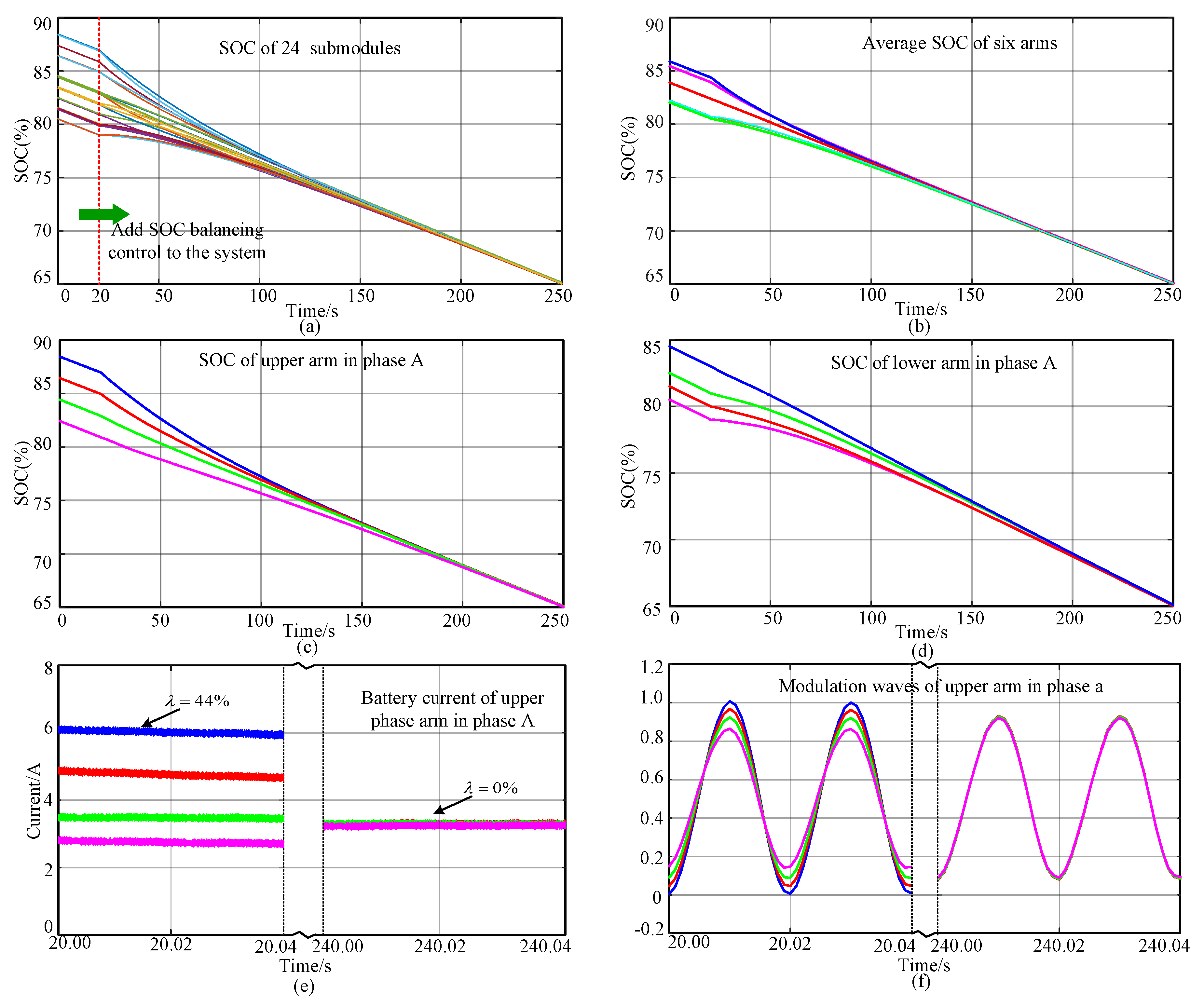
Figure 8 is the simulation results of traditional SOC balancing control method used in [25]. The power of AC side and DC side are: Pdc = 4.8 KW, Pac = 9.6 KW. Figure 8a is the SOC of 24 submodules in MMC-BESS. At time T = 20 s, the SOC balancing control is added to the system, and then the SOC starts to converge. However the convergence rate is too small for the whole BESS. Figure 8b shows the average SOC of six arms, which can denote the SOC balancing control among phases and between arms. Figure 8c,d are the SOC of upper and lower arm in phase A. It is obvious that the convergence rate of whole BESS is mainly limited by SOC balancing control within arms. The analysis in Section 3.2 indicates that the tolerance for battery power unbalance is limited in 11% when m = 0.8. In Figure 8e, the maximum power unbalance is 10% and over-modulation almost occurs as shown in Figure 8f. It means that the SOC convergence rate has already reached the limit, however the SOC convergence of the whole BESS is still so poor.
Figure 9 is the simulation results of the proposed SOC balancing control, and the power configuration is the same as the simulation in Figure 8. The SOC of all submodules is shown in Figure 9a. At time T = 20 s, the SOC balancing control is added to the control system, and then the SOC of the whole BESS converges to the same value at around T = 200 s. Figure 9b shows the average SOC of six arms. Figure 9c,d are the SOC of upper and lower arm in phase A. In Figure 8, the tolerance for battery power unbalance is about 50%, and the control design is according to (39). At T = 20 s, the difference of SOC among submodules is the greatest, but the battery power unbalance is still limited into the allowed values and over-modulation does not occur.
Compared with the traditional method, the proposed SOC balancing control method improves the tolerance for battery power unbalance. Therefore, the efficiency of SOC balancing control can be greatly improved and over-modulation also can be effectively avoided.
5.2. Experiment Results
The detailed simulation results above have verified the effectiveness of the analysis and proposed control strategy. For further verification, a downscaled prototype is built in this paper as shown in Figure 10. Owing to the limitation of experiment conditions. The utilized battery is the lead-acid battery, and the detailed parameters are shown in Table 2.
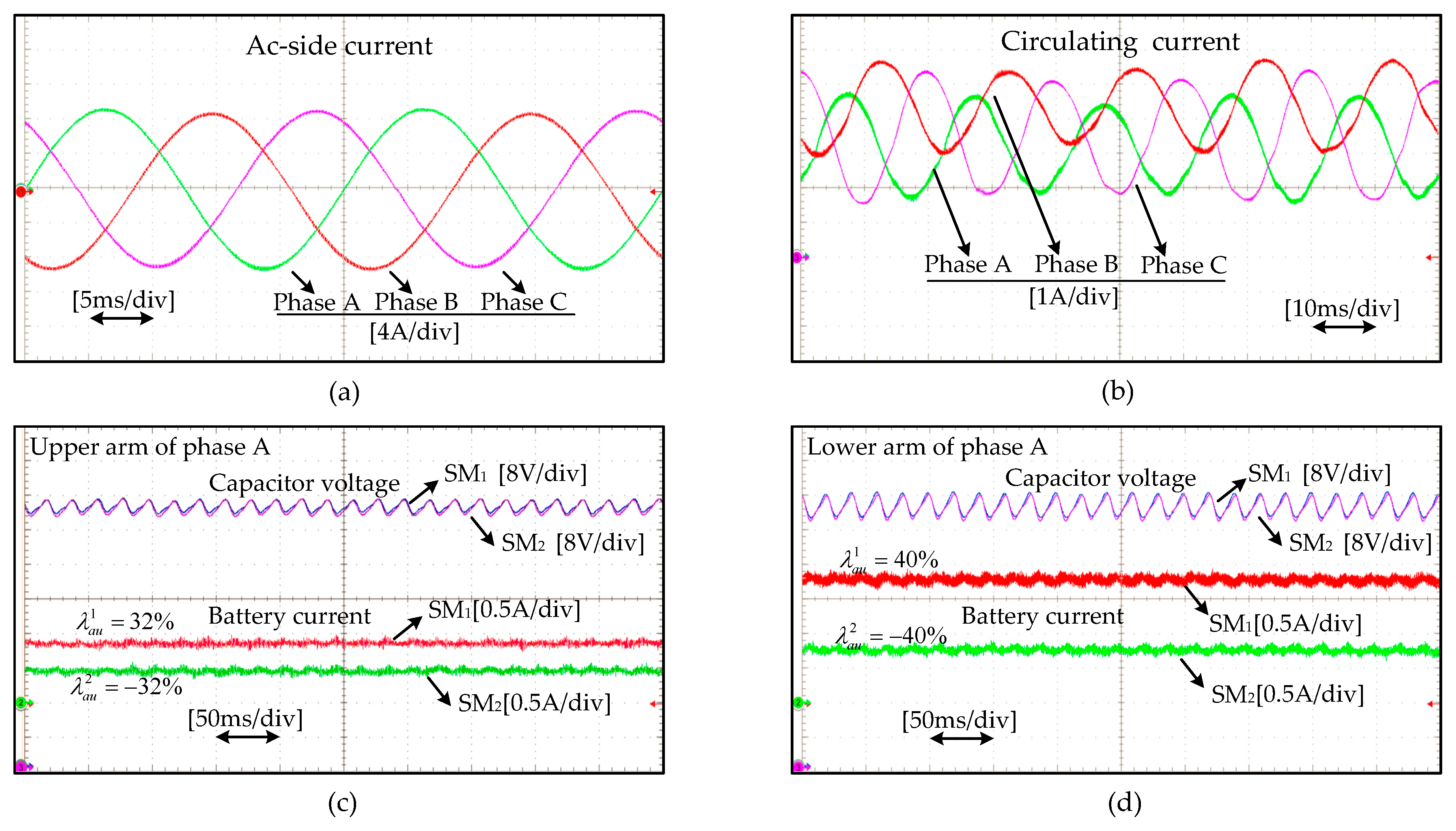
Figure 11 is the steady-state waveforms of MMC-BESS, and the BESS works in charging mode. Figure 11a is the ac-side current, and Figure 11b shows the circulating current of three phases. Circulating current contains DC component and fundamental frequency component. The dc circulating currents of phase A, B, and C are different, which are controlled to balance the SOC among legs. Fundamental frequency circulating currents are injected to balance the SOC between phase arms. Figure 11c,d show the submodule capacitor voltages and battery currents of upper arm and lower arm in phase A. The ripples of capacitor voltage are filtered by the notch filter, so there is nearly no low-frequency component in the battery current. The maximum battery power unbalance degree is about 40%, which is much greater than the allowed unbalance degree in traditional method.
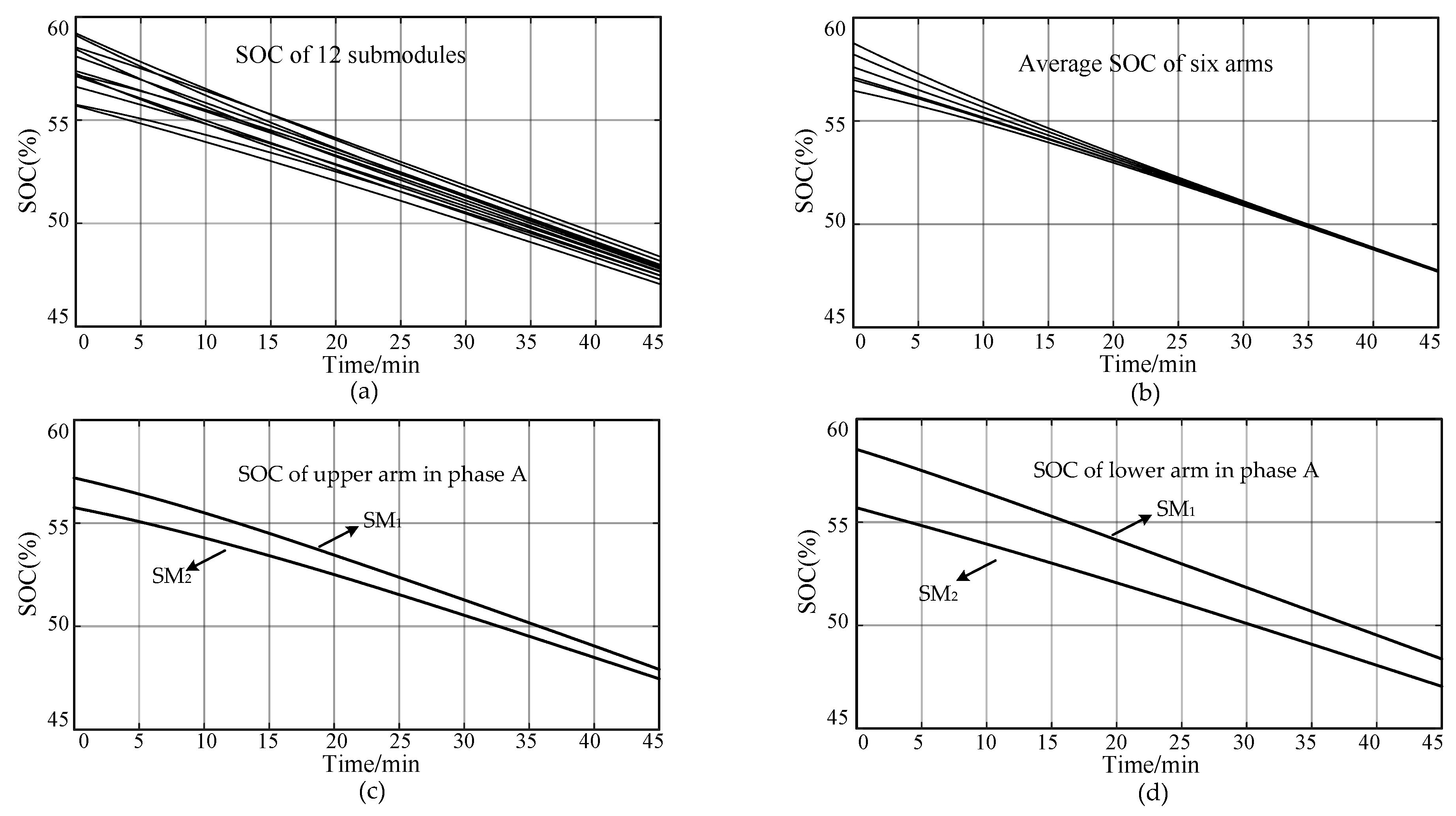
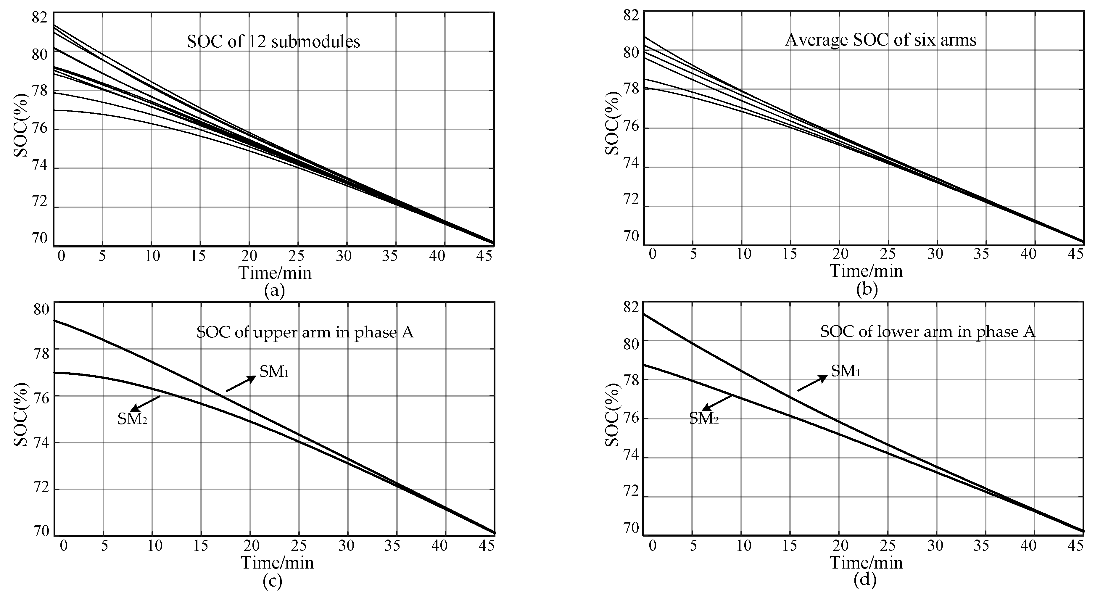
Figure 12 is the experiment result of optimized SOC balancing control proposed in this paper. The SOC of 12 submodules is between 76–82% at T = 0, and the SOC of all submodules converges to 70% at T = 40 min. Figure 13 is the experiment result of traditional SOC balancing control. The SOC of 12 submodules is between 55–60% at T = 0. Figure 12a and Figure 13a shows the SOC of all submodules. it is obvious that the convergence of proposed method is much better than that of traditional method. Figure 12b and Figure 13b denote the SOC balancing control among phases and between arms. The convergence of the two methods are basically the same. In Figure 12c,d and Figure 13c,d, the SOC balancing control within arms of the proposed method is much faster than that of traditional method. That is why the efficiency of the proposed method is much higher than that of traditional method.
6. Conclusions
This paper mainly focuses on the SOC balancing control of MMC-BESS, aiming to improve the efficiency of SOC balancing control. The investigation indicates that the battery power unbalance can lead to the over-modulation of submodules, limiting the efficiency of SOC balancing control. Then the tolerance for battery power unbalance is defined to quantize the convergence of SOC balancing control. The submodule voltage regulation method is studied in detail by introducing the DC factor and AC factor. The linear programming method is introduced to reach the maximum tolerance in different operation modes. Based on the analysis, by choosing appropriate submodule voltage regulation method, the efficiency of SOC balancing control is improved greatly. To avoid over-modulation of submodules, the controller of SOC balancing control is also optimally designed. In this way, the convergence rate of SOC is greatly improved compared with traditional method. Finally, the analysis and proposed SOC balancing method are verified through detailed simulation and experiment results.
Author Contributions
Y.M. proposed the main idea, performed the theoretical analysis, and wrote the paper. H.L. contributed the experiment materials and gave some suggestions. Z.W. and Z.Z. performed the experiments.
Funding
This research was funded by National Natural Science Foundation of China, grant number 51741703.
Conflicts of Interest
The authors declare no conflict of interest.
References
- Qian, H.; Zhang, J.; Lai, J.S.; Yu, W. A high-efficiency grid-tie battery energy storage system. IEEE Trans. Power Electron. 2011, 26, 886–896. [Google Scholar] [CrossRef] [Green Version]
- Alipoor, Y.; Miura, Y.; Ise, T. Power System Stabilization Using Virtual Synchronous Generator with Alternating Moment of Inertia. IEEE J. Emerg. Sel. Top. Power Electron. 2015, 3, 451–458. [Google Scholar] [CrossRef]
- Jiang, Q.Y.; Gong, Y.Z.; Wang, H.J. A battery energy storage system dual-layer control strategy for mitigating wind farm fluctuations. IEEE Trans. Power Syst. 2013, 28, 3263–3273. [Google Scholar] [CrossRef]
- Baruschka, L.; Mertens, A. Comparison of cascaded H-bridge and modular multilevel converters for BESS application. In Proceedings of the Energy Conversion Congress and Exposition, Phoenix, AZ, USA, 17–22 September 2011; pp. 909–916. [Google Scholar] [CrossRef]
- Soong, T.; Lehn, P.W. Evaluation of emerging modular multilevel converters for BESS applications. IEEE Trans. Power Deliv. 2014, 29, 2086–2094. [Google Scholar] [CrossRef]
- Trintis, I.; Munk-Nielsen, S.; Teodorescu, R. A new modular multilevel converter with integrated energy storage. In Proceedings of the IECON 2011-37th Annual Conference on IEEE Industrial Electronics Society, Melbourne, Australia, 7–10 November 2011; pp. 1075–1080. [Google Scholar] [CrossRef]
- Coppola, M.; Del Pizzo, A.; Iannuzzi, D. A power traction converter based on modular multilevel architecture integrated with energy storage devices. In Proceedings of the Electrical Systems for Aircraft, Railway and Ship Propulsion (ESARS), Pittsburgh, PA, USA, 14–18 September 2014; pp. 1–7. [Google Scholar] [CrossRef]
- Hillers, A.; Stojadinovic, M.; Biela, J. Systematic comparison of modular multilevel converter topologies for battery energy storage systems based on split batteries. In Proceedings of the 17th Europe Conference Power Electronics, Geneva, Switzerland, 8–10 September 2015; pp. 1–9. [Google Scholar] [CrossRef]
- Soong, T.; Lehn, P.W. Internal Power Flow of a Modular Multilevel Converter with Distributed Energy Resources. IEEE J. Emerg. Sel. Top. Power Electron. 2014, 2, 1127–1138. [Google Scholar] [CrossRef]
- Gao, F.; Zhang, L.; Zhou, Q. State-of-charge balancing control strategy of battery energy storage system based on modular multilevel converter. In Proceedings of the IEEE Energy Conversion Congress and Exposition, Pittsburgh, PA, USA, 14–18 September 2014; pp. 2567–2574. [Google Scholar] [CrossRef]
- Zhang, L.; Gao, F.; Li, N. Interlinking modular multilevel converter of hybrid AC-DC distribution system with integrated battery energy storage. In Proceedings of the IEEE Energy Conversion Congress and Exposition, Montreal, QC, Canada, 20–24 September 2015; pp. 70–77. [Google Scholar] [CrossRef]
- Bala, S. The effect of low frequency current ripple on the performance of a Lithium Iron Phosphate (LFP) battery energy storage system. In Proceedings of the IEEE Energy Conversion Congress and Exposition, Raleigh, NC, USA, 15–20 September 2012; pp. 3485–3492. [Google Scholar] [CrossRef]
- Puranik, I.; Zhang, L.; Qin, J. Impact of Low-Frequency Ripple on Lifetime of Battery in MMC-based Battery Storage Systems. In Proceedings of the IEEE Energy Conversion Congress and Exposition, Portland, OR, USA, 23–27 September 2018; pp. 2748–2752. [Google Scholar] [CrossRef]
- Novakovic, B.; Nasiri, A. Modular multilevel converter for wind energy storage applications. IEEE Trans. Ind. Electron. 2017, 64, 8867–8876. [Google Scholar] [CrossRef]
- Ma, Y.J.; Lin, H.; Wang, Z.; Wang, T. Capacitor voltage balancing control of modular multilevel converters with energy storage system by using carrier phase-shifted modulation. In Proceedings of the IEEE Applied Power Electronics Conference and Exposition, Tampa, FL, USA, 26–30 March 2017; pp. 1821–1828. [Google Scholar] [CrossRef]
- Soong, T.; Lehn, P.W. Assessment of Fault Tolerance in Modular Multilevel Converters with Integrated Energy Storage. IEEE Trans. Power Electron. 2016, 31, 4085–4095. [Google Scholar] [CrossRef]
- Hagiwara, M.; Akagi, H. Control and experiment of pulse width-modulated modular multilevel converters. IEEE Trans. Power Electron. 2009, 24, 1737–1746. [Google Scholar] [CrossRef]
- Adam, G.P.; Anaya-Lara, O.; Burt, G.M. Modular multilevel inverter: Pulse width modulation and capacitor balancing technique. IET Power Electron. 2010, 3, 702–715. [Google Scholar] [CrossRef]
- Han, W.; Zou, C.; Zhou, C. Estimation of cell SOC evolution and system performance in module-based battery charge equalization systems. IEEE Trans. Smart Grid 2018. [Google Scholar] [CrossRef]
- Vasiladiotis, M.; Rufer, A. Analysis and Control of Modular Multilevel Converters with Integrated Battery Energy Storage. IEEE Trans. Power Electron. 2015, 30, 163–175. [Google Scholar] [CrossRef]
- Quraan, M.; Tricoli, P.D.; Arco, S. Efficiency assessment of modular multilevel converters for battery electric vehicles. IEEE Trans. Power Electron. 2017, 32, 2041–2051. [Google Scholar] [CrossRef]
- Quraan, M.; Yeo, T.; Tricoli, P. Design and control of modular multilevel converters for battery electric vehicles. IEEE Trans. Power Electron. 2016, 31, 507–517. [Google Scholar] [CrossRef]
- Zhang, L.; Tang, Y.; Yang, S. Decoupled Power Control for A Modular Multilevel Converter-Based Hybrid AC-DC Grid Integrated with Hybrid Energy Storage. IEEE Trans. Ind. Electron. 2018. [Google Scholar] [CrossRef]
- Chen, Q.; Li, R. Analysis and Fault Control of Hybrid Modular Multilevel Converter with Integrated Battery Energy Storage System. IEEE J. Emerg. Sel. Top. Power Electron. 2017, 5, 64–79. [Google Scholar] [CrossRef]
- Liang, H.; Guo, L.; Song, J. State-of-Charge Balancing Control of a Modular Multilevel Converter with an Integrated Battery Energy Storage. Energies 2018, 11, 873. [Google Scholar] [CrossRef]
- Debnath, S.; Qin, J.; Saeedifard, M. Control and stability analysis of modular multilevel converter under low-frequency operation. IEEE Trans. Ind. Electron. 2015, 62, 5329–5339. [Google Scholar] [CrossRef]
Figure 1.
Wind energy generation system: (a) structure of offshore wind farm; (b) topology of MMC-BESS.
Figure 1.
Wind energy generation system: (a) structure of offshore wind farm; (b) topology of MMC-BESS.

Figure 2.
Power flow of MMC-BESS: (a) power flow among phases and between arms; (b) power flow among submodules within arms.
Figure 2.
Power flow of MMC-BESS: (a) power flow among phases and between arms; (b) power flow among submodules within arms.
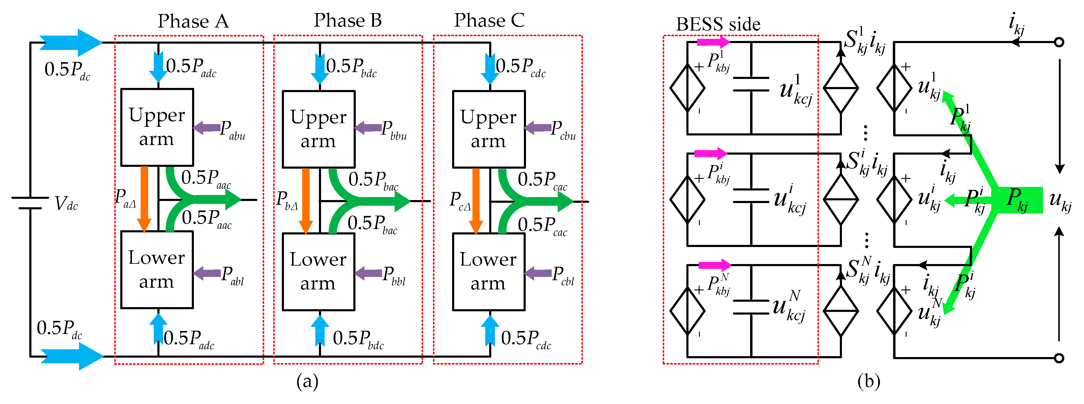
Figure 3.
General control structure of MMC-BESS.

Figure 4.
Choosing appropriate DC and AC factor for maximum tolerance in different conditions: (a) when ; (b) when ; (c) when ; (d) when .
Figure 4.
Choosing appropriate DC and AC factor for maximum tolerance in different conditions: (a) when ; (b) when ; (c) when ; (d) when .
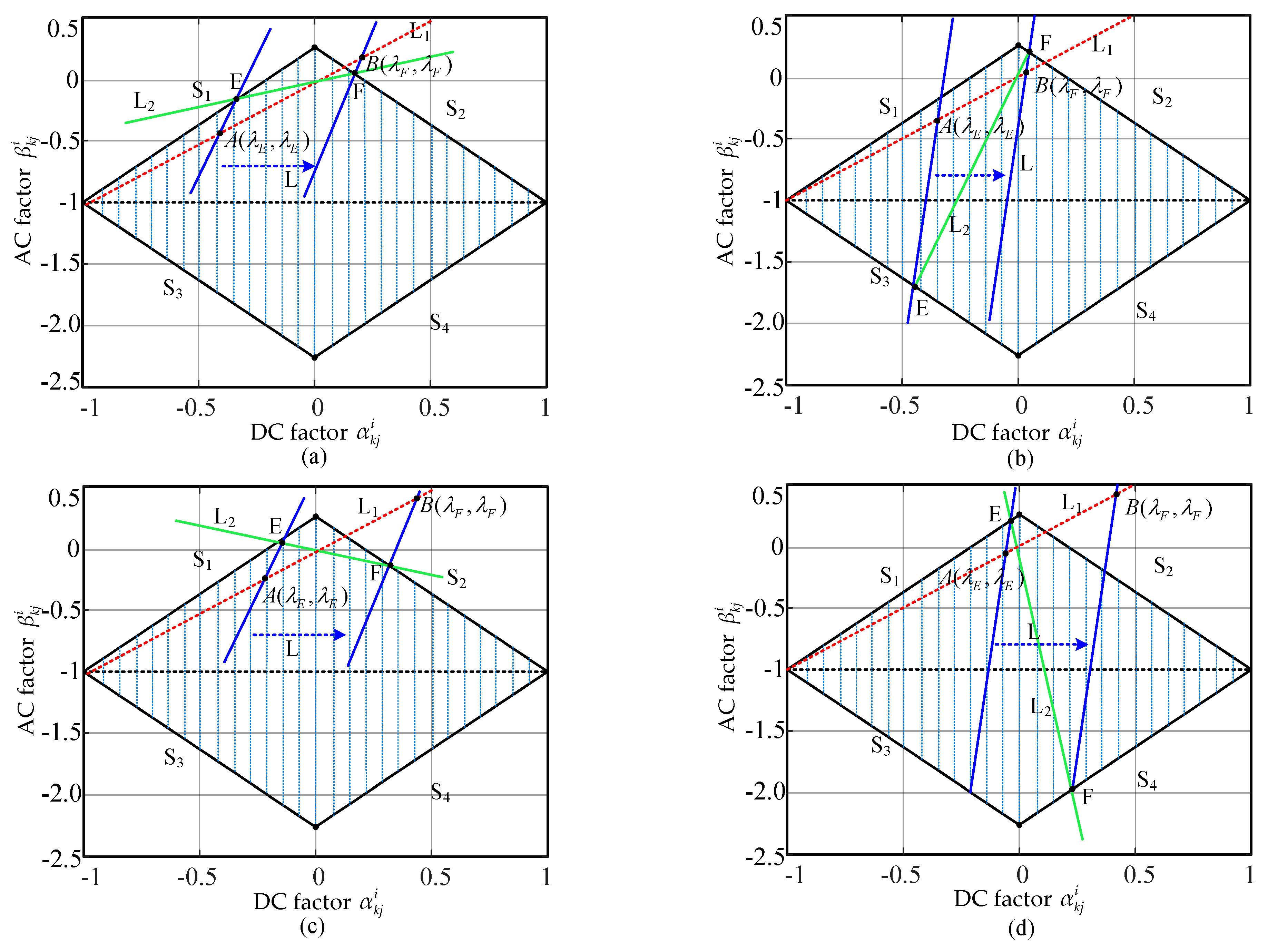
Figure 5.
Power regulation capability of submodules when m = 0.8: (a) when power ratio 0 < ξkj ≤ 1; (b) when power ratio ξkj > 1; (c) when power ratio ξkj ≤ −1/m; (d) when power ratio −1/m < ξkj ≤ 0.
Figure 5.
Power regulation capability of submodules when m = 0.8: (a) when power ratio 0 < ξkj ≤ 1; (b) when power ratio ξkj > 1; (c) when power ratio ξkj ≤ −1/m; (d) when power ratio −1/m < ξkj ≤ 0.

Figure 6.
Modified SOC balancing control within arms.
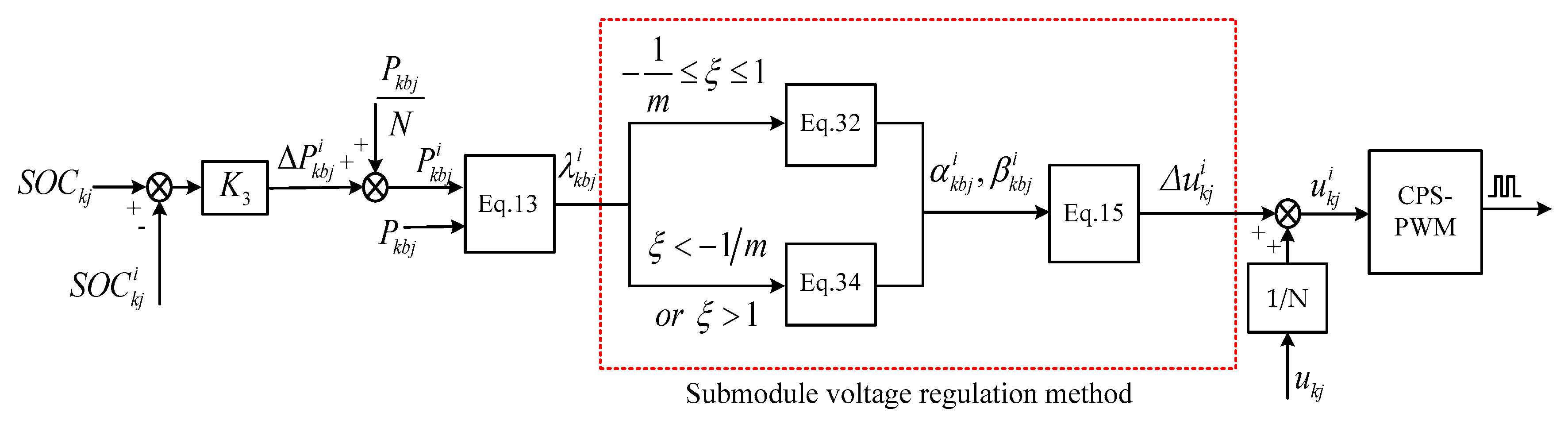
Figure 7.
Tolerance for battery power unbalance: (a) comparison of different submodule voltage regulation methods; (b) influence of modulation ratio.
Figure 7.
Tolerance for battery power unbalance: (a) comparison of different submodule voltage regulation methods; (b) influence of modulation ratio.
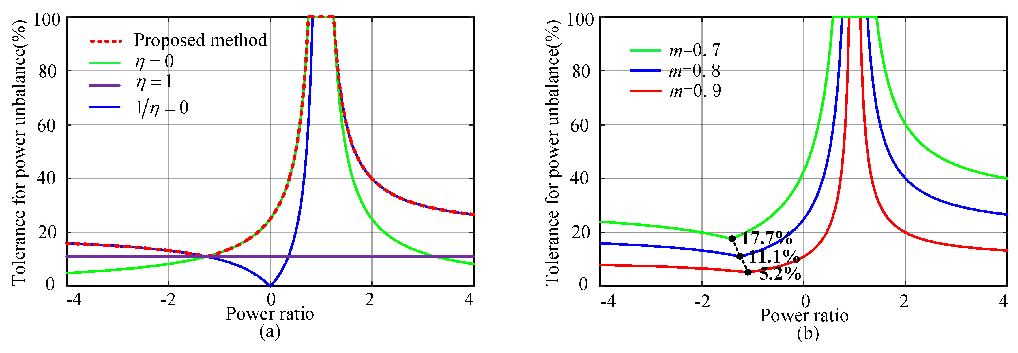
Figure 8.
Simulation results of traditional SOC balancing control: (a) SOC of all submodules; (b) average SOC of six arms; (c) SOC of upper arm in phase a; (d) SOC of lower arm in phase a; (e) battery current of phase arm in phase a; (f) modulation waves of upper arm in phase A.
Figure 8.
Simulation results of traditional SOC balancing control: (a) SOC of all submodules; (b) average SOC of six arms; (c) SOC of upper arm in phase a; (d) SOC of lower arm in phase a; (e) battery current of phase arm in phase a; (f) modulation waves of upper arm in phase A.

Figure 9.
Simulation results of the modified SOC balancing control: (a) SOC of all submodules; (b) average SOC of all phase arms; (c) SOC of upper arm in phase a; (d) SOC of lower arm in phase a; (e) battery current of phase arm in phase A; (f) modulation waves of upper arm in phase A.
Figure 9.
Simulation results of the modified SOC balancing control: (a) SOC of all submodules; (b) average SOC of all phase arms; (c) SOC of upper arm in phase a; (d) SOC of lower arm in phase a; (e) battery current of phase arm in phase A; (f) modulation waves of upper arm in phase A.

Figure 10.
Prototype of three phase MMC-BESS.

Figure 11.
Steady-state waveforms of MMC-BESS with optimized SOC balancing control method: (a) AC-side current; (b) circulating current; (c) capacitor voltage and battery current of upper arm in phase A; (d) capacitor voltage and battery current of lower arm in phase A.
Figure 11.
Steady-state waveforms of MMC-BESS with optimized SOC balancing control method: (a) AC-side current; (b) circulating current; (c) capacitor voltage and battery current of upper arm in phase A; (d) capacitor voltage and battery current of lower arm in phase A.

Figure 12.
Experiment results of modified SOC balancing control method: (a) SOC of all submodules; (b) average SOC of phase arms; (c) SOC of upper arm in phase A; (d) SOC of lower arm in phase A.
Figure 12.
Experiment results of modified SOC balancing control method: (a) SOC of all submodules; (b) average SOC of phase arms; (c) SOC of upper arm in phase A; (d) SOC of lower arm in phase A.

Figure 13.
Experiment results of traditional SOC balancing control method: (a) SOC of all submodules; (b) average SOC of phase arms; (c) SOC of upper arm in phase A; (d) SOC of lower arm in phase A.
Figure 13.
Experiment results of traditional SOC balancing control method: (a) SOC of all submodules; (b) average SOC of phase arms; (c) SOC of upper arm in phase A; (d) SOC of lower arm in phase A.

Table 1.
Parameters of simulation model.
| Quantity | Value | Comment |
|---|---|---|
| Vdc | 400 V | DC-Link voltage |
| m | 0.8 | Modulation ratio |
| Pac | 10 KW | Nominal AC-side power |
| Vsm | 100 V | Submodule capacitor voltage |
| N | 4 | Number of submodules per arm |
| C | 5 mF | Submodule capacitance |
| La | 5 mH | Arm inductor |
| Lbat | 10 mH | DC/DC side inductor |
| Vbat | 60 V | Nominal battery voltage |
| Cbat | 1 Ah | Nominal battery capacity |
| fM | 2 kHz | MMC side switching frequency |
| fB | 10 kHz | DC/DC converter frequency |
Table 2.
Parameters of experiment prototype.
| Quantity | Value | Comment |
|---|---|---|
| Vdc | 120 V | DC-Link voltage |
| m | 0.8 | Modulation ratio |
| Pac | 2 KW | Nominal AC-side power |
| Vsm | 60 V | Submodule capacitor voltage |
| N | 2 | Number of submodules per arm |
| C | 3 mF | Submodule capacitance |
| La | 5 mH | Arm inductor |
| Lbat | 10 mH | DC/DC side inductor |
| Vbat | 36 V | Nominal battery voltage |
| Cbat | 12 Ah | Nominal battery capacity |
| fM | 5 kHz | MMC side switching frequency |
| fB | 10 kHz | DC/DC converter frequency |
© 2018 by the authors. Licensee MDPI, Basel, Switzerland. This article is an open access article distributed under the terms and conditions of the Creative Commons Attribution (CC BY) license (http://creativecommons.org/licenses/by/4.0/).
Share and Cite
MDPI and ACS Style
Ma, Y.; Lin, H.; Wang, Z.; Ze, Z. Modified State-of-Charge Balancing Control of Modular Multilevel Converter with Integrated Battery Energy Storage System. Energies 2019, 12, 96. https://doi.org/10.3390/en12010096
AMA Style
Ma Y, Lin H, Wang Z, Ze Z. Modified State-of-Charge Balancing Control of Modular Multilevel Converter with Integrated Battery Energy Storage System. Energies. 2019; 12(1):96. https://doi.org/10.3390/en12010096
Chicago/Turabian StyleMa, Yajun, Hua Lin, Zhe Wang, and Zuyao Ze. 2019. "Modified State-of-Charge Balancing Control of Modular Multilevel Converter with Integrated Battery Energy Storage System" Energies 12, no. 1: 96. https://doi.org/10.3390/en12010096
Note that from the first issue of 2016, this journal uses article numbers instead of page numbers. See further details here.