Experimental Research for Stabilizing Offshore Floating Wind Turbines


1
School of Engineering, Newcastle University, Newcastle upon Tyne NE1 7RU, UK
2
School of Mechanical Engineering, Shanghai Jiaotong University, Shanghai 200240, China
3
School of Mechanical Engineering, Hunan Institute of Engineering, Xiangtan 411104, China
4
School of Naval Architecture, Ocean & Civil Engineering, Shanghai Jiaotong University, Shanghai 200240, China
*
Author to whom correspondence should be addressed.
Energies 2019, 12(10), 1947; https://doi.org/10.3390/en12101947
Submission received: 6 March 2019
/
Revised: 10 May 2019
/
Accepted: 14 May 2019
/
Published: 21 May 2019
(This article belongs to the Special Issue Power System for Offshore Renewable Energy)
Abstract
:Floating turbines are attracting increasing interest today. However, the power generation efficiency of a floating turbine is highly dependent on its motion stability in sea water. This issue is more marked, particularly when the floating turbines operate in relatively shallow water. In order to address this issue, a new concept motion stabilizer is studied in this paper. It is a completely passive device consisting of a number of heave plates. The plates are connected to the foundation of the floating wind turbine via structural arms. Since the heave plates are completely, rather than partially, exposed to water, all surfaces of them can be fully utilized to create the damping forces required to stabilize the floating wind turbine. Moreover, their stabilizing effect can be further amplified due to the application of the structural arms. This is because torques will be generated by the damping forces via the structural arms, and then applied to stabilizing the floating turbine. To verify the proposed concept motion stabilizer, its practical effectiveness on motion reduction is investigated in this paper. Both numerical and experimental testing results have shown that after using the proposed concept stabilizer, the motion stability of the floating turbine has been successfully improved over a wide range of wave periods even in relatively shallow water. Moreover, the comparison has shown that the stabilizer is more effective in stabilizing the floating wind turbine than single heave plate does. This suggests that the proposed concept stabilizer may provide a potentially viable solution for stabilizing floating wind turbines.
1. Introduction
Attributing to the successful implementation of the Round 1 to Round 3 offshore wind development programs, the UK consistently tops the international rankings for offshore wind market. It is predicted that the installed capacity of offshore wind in the UK will increase from the present 5.07 GW to 30 GW by 2030 and 50 GW by 2050, which will attract a significant investment in the UK [1]. However, despite the bright future the current development of the offshore wind industry is still facing a number of challenges, one of which is the high Cost of Energy (COE). To lower the COE of offshore wind power, almost all existing and planned offshore wind projects in the UK are or will be located in the shallow water near the coast. Currently, the average water depth of the grid-connected offshore wind farms in the UK is only 27.2 m [2], where the proven fixed wind turbine foundation technologies can be readily applied. However, the extensive application of the fixed steel foundations is raising concern today. The reasons are as follows: (1) The steel foundations have led to a high COE of offshore wind power due to the costly manufacturing, transportation, and installation. The survey has shown that fixed foundations account for nearly 40% of the total cost of bringing an offshore wind turbine to fruition [3]. This makes the offshore wind industry difficult to make profit even without considering the operation and maintenance costs of wind turbines, which on average accounts for 20–25% of the total cost of wind power project [4]. (2) The offshore wind farms move further offshore [2], where there are better wind resources and the turbines can potentially achieve higher power capacity factors [5,6]. But farther offshore sites are often associated with deeper water. Siemens’ experience suggests that the application of fixed foundations in deep water will become prohibitively expensive due to the increased installation difficulties [7,8]. For these reasons, floating wind turbines are attracting increasing interest in recent years and are now regarded as a potential driver to lower the COE due to their potential advantages of easier installation, transportation, and decommission. For example, floating wind turbines can be assembled onshore and then towed to the offshore site by boat. That will no longer require large purpose-designed installation and transportation vessels, thereby lowering the COE. In addition, the decommissioning of a floating turbine is also relatively easier than decommissioning a fixed turbine. Due to these potential advantages, the research and application of floating wind turbines are booming today. For example, the Hywind Scotland, a 30 MW floating wind farm consisting of five 6 MW turbines, has started to deliver electricity to the Scottish grid in 2017 [9]; a 14 MW pilot floating wind farm run by Marubeni, consisting of one 2 MW, one 7 MW, and one 5 MW turbines, was developed off the coast of Fukushima in Japan in 2016 [10]. Besides these, a few floating wind farms are either planned or constructed as well. For example, the Windfloat Atlantic project, a 25 MW floating wind project in Viana do Castelo off the north coast of Portugal, is under construction. It will come into operation in 2019 [11]. Meanwhile, France also has the potential to be a big player of floating wind farms in the future. France’s Energy Ministry has awarded contract to build two 24 MW floating wind projects in the Mediterranean Sea, which are to be commissioned by 2020 [12].
2. Challenges in the Present Application of Floating Wind Turbines
At present, the application of floating wind turbines is facing many challenging issues, one of which is the lack of a proven concept of floating foundation. The reasons of concern are explained below.
2.1. Limitations of Existing Floating Wind Turbines
As mentioned earlier, the majority of existing and planned offshore wind projects in the UK are or will be located in nearshore shallow water. For example, the 4.8 GW Dogger Bank, one of the largest offshore wind projects in the UK, will be built in water of depth ranging from 18 m to 63 m [13,14]. However, the authors’ preliminary research has shown that it is more difficult to achieve a stable floating wind turbine in shallow water than in deep water [14]. This can be inferred from the results shown in Figure 1, where H refers to water depth, the x-axis is wave period, and the y-axis is the pitch motion of a floating turbine.
From Figure 1, it is seen that pitch motion, which may have a big influence on the power generation efficiency of a floating wind turbine, increases with decreasing water depth H. This partially explains why the majority of existing floating wind turbines were erected or are planned to be erected in deep water rather than in shallow water. Some of these existing floating turbines are illustrated in Figure 2 and briefly reviewed in Table 1.
From Table 1, it is seen that nearly all existing floating wind turbines are installed in >50 m depth water. They can be roughly classified into the following three categories according to the types of their supporting foundations:
- Spar-supported turbines—were initially designed for application in deep water, where the sufficient buoyancy force and desired motion stability of the turbine can be easily achieved. However, the mean water depth of the North Sea is only 90 m [15] and the existing and planned offshore wind farms in the UK are or will be developed mainly in nearshore shallow water. From this point of view, this kind of floating turbine cannot be widely adopted in the future British offshore wind market if it is not re-designed for application in relatively shallow water.
- Semi-submersible floater (SSF)-supported turbines—can easily obtain sufficient buoyancy in shallow water due to the use of multiple floaters. However, due to the large water plane areas of the floaters, the motion stability of this kind of turbine is sensitive to sea waves. This is a matter of concern because unstable motion will reduce the power generation efficiency of the turbine. To address this issue, this kind of turbine is usually equipped with active ballast systems. Taking WindFloat as an example, the turbine is mounted over one of the three floating columns. An alignment sensor is configured to detect the pitch angle of the turbine tower. Then based on the measurement result, water is pumped from one column to another to adjust the alignment of the tower. Apparently, such a turbine stabilization method is unable to respond quickly. There is difficulty to adapt it to the instantaneous changes in wind and wave loads.
- Tension leg platform (TLP)-supported turbines—are inspired by a deep-water design in the oil and gas industry. These structures are stable; however, prohibitively expensive [16]. Moreover, owing to the use of steel tethers, their cost will exponentially increase with the increase of water depth. For example, the PelaStar turbine, which is going to be installed in >50 m depth water, would cost more than £20 million [17]. There is no doubt that this kind of turbine is not favored by the wind farm developers, particularly, when they are facing pressure to lower the COE.
In summary, in comparison with the TLP-supported turbines, the affordability of the Spar-supported and SSF-supported turbines makes them more likely to be extensively used in the future offshore wind farms, if the Spar-supported turbines can adapt to application in relatively shallow water and the SSF-supported turbines can be improved in motion stability.
2.2. Limitations of Existing Measures That are Taken for Stabilizing Floating Wind Turbines
The large pitch motion of a floating turbine may disturb the pitch control of its blades, consequently leading to the decrease of power generation efficiency. This implies that the application of floating wind turbines in shallow water will experience more challenges in operation because (a) it may not be easy to achieve the power production target due to the unstable motion of the turbine [14]; (b) the large movements may lead to more reliability issues or even the sinking of the turbine in the worst situation. For example, the 1:6 test model of Norwegian Sway floating turbine, which was installed in 25 m depth water, sank in extreme weather in 2011 [18].
In essence, the unstable motion of a floating turbine is due to the unbalanced wind and wave forces and moments acting on the turbine. They vary over time in both strength and direction. This motivates the research for stabilizing floating wind turbines in recent years. To date, the achieved techniques can be roughly classified into the following three groups:
Group A—stabilizing floating wind turbines via blade pitch control [19,20,21]. This method is popularly used in the present wind power practice. However, it shows the following defects in practical application:
- It requires the blade pitch control system to be run frequently. It is well known that blade pitch control system is vulnerable to failure [4]. The frequent pitch control operation will further worsen the situation and make it more unreliable;
- The operation of blade pitch control system is based on the data collected by the wind farm Supervisory Control and Data Acquisition (SCADA) system. As the SCADA data is usually collected using a low sampling frequency, the method that is developed based on blade pitch control is unable to respond to the instantaneous changes in wind and wave loads;
- It can limit the movements caused by unstable wind loading. However, it is unable to reduce those caused by inconsistent waves and tidal current;
- It is not capable of dealing with both power generation efficiency and the motion stability of the turbine simultaneously. Therefore, how to improve motion stability while not sacrificing the power generation efficiency of the turbine is still an open issue remaining to be resolved.
Group B—stabilizing floating wind turbines using additional control actuations [22,23,24]. In spite of the demonstrated success, drawbacks with this type of approach are evident. For example, Tuned Liquid Column Damper (TLCD) [22] has a low actuation bandwidth and requires significant modification of the floating turbine structures to host the TLCD; the application of Tuned-Mass Damper (TMD) [23,24], which is characterized by a heavy mass moving in large strokes, also requires the re-design of wind turbine nacelle. There is no doubt that the modification or re-design of wind turbine structures will cause extra cost inevitably.
Group C—stabilizing floating wind turbines via active mooring line control [25,26]. Artificial muscle was studied firstly in the field of robotics and found to have very high power density, high efficiency, and low hysteresis. Artificial muscle-based actuators are also desirable for the design and application of active mooring lines due to the fact that artificial muscle-based actuators can be easily integrated to the junction of the mooring lines and floating platforms. However, the development of such an actuator often requires multiple bundles of artificial muscle clustered as an array; this is very costly. In addition, at present this technique is still at the stage of preliminary research. Further effort is required to verify its applicability, effectiveness, reliability, and durability in real-life offshore engineering.
The foregoing highlights that achieving a stable floating turbine, particularly in relatively shallow water, is still a challenging issue that has not been successfully solved today. Motivated by this, a new concept motion stabilizer is studied in this paper. The details of the research are reported below.
3. Proposal of a New Concept Motion Stabilizer
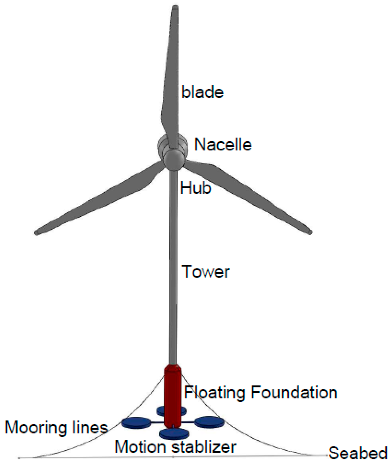
Scientists have studied how dragonflies use four wings, rather than two as observed in other insects, to achieve stable suspension, efficient flying, and fast maneuvers in the air. It is known that the dragonfly’s fore and hind wings are controlled by separate muscles. Due to this distinctive feature, the dragonfly’s wing movements are dependent on the phase relation of the four wings during various maneuvers. When hovering, the fore and hind wings tend to beat out of phase; during takeoff, they tend to beat closer in phase. This has never been observed from other insects. One plausible explanation of the reason why a dragonfly varies the phase in different maneuvers is that alternating the down-stroke can reduce body oscillation [27]. Inspired by such an interesting finding, a new concept motion stabilizer is proposed in this paper dedicatedly for stabilizing offshore floating wind turbines. The schematic diagram of a four-wing motion stabilizer that is specifically designed for Spar-supported turbines is shown in Figure 3.
As shown in Figure 3, the proposed stabilizer will be installed on the bottom plane of the spar foundation of the floating turbine. The damping forces required to stabilize the turbine will be created by the four heave plates, which are connected to the spar foundation via four structural arms. Considering that power electric control systems are prone to develop faults in wet and corrosive marine environments, the proposed stabilizer will be a completely passive device without using any power electronic components or control systems. So, it is likely to be much more reliable in practical use. Besides this, the proposed stabilizer also has the following merits:
(1) The damping forces created by it are adaptive to the external loads.
This merit can be easily explained using Morrison equation [28], which provides an estimate of the force acting on the heave plate due to the surrounding water. According to Morrison equation, the force acting on each heave plate comprises inertial and drag components and , i.e.,
where
is the volume of the heave plate; and are the inertial and drag coefficients of the heave plate; refers to water density; stands for the relative speed between the heave plate and water flow; and is the projected area of the heave plate normal to the flow.
From the above equations, it is seen that the damping force created by every heave plate of the stabilizer is a function of speed and acceleration . Since the four heave plates of the stabilizer are installed at the positions in four different directions where the flow has different velocities and accelerations, the damping forces created by the four plates will be different from each other. This is similar to the conditions acting on the dragonfly’s four wings. From Equations (1)–(3), it can be inferred that the stronger the motion of the floating turbine, the larger the damping force created by the heave plates of the stabilizer will tend to be. Therefore, the operation of the proposed concept stabilizer is fully adaptive to the external loads in different directions, although the stabilizer is a completely passive device without adopting any active control.
(2) It is able to respond to external loads instantly without the lag response issue that always exists in active control systems.
The motion of a floating turbine can be affected by many factors, such as wind above water surface, waves on water surface, and tidal current under water surface. For an active control system, these factors need to be accurately measured using different types of sensors. The application of these sensors not only increases the capital cost of the system but also lowers the efficiency and accuracy of control, because error may be accumulated during the process of data measurement and data processing. Additionally, the complex calculation in the process of data analysis and system identification will take time and consequently decrease the efficiency of control. By contrast, the proposed concept stabilizer does not use any sensor or active control system. It will respond instantly to the aggregated forces acting on the heave plates. This will make the stabilizer more efficient in motion reduction.
(3) It is small in geometric size, thus is easy to install and replace.
As mentioned earlier, the heave plates of the stabilizer are connected to wind turbine foundation via four structural arms. For the sake of simplicity, the connection between the four arms and wind turbine foundation is rigid, not hinged. The application of these structural arms will amplify the motion reduction effect of the stabilizer, as the moments rather than the forces will be applied to stabilize the floating turbine. Attributing to this unique feature, in theory the size of the heave plates can be reduced.
4. Tests of the Proposed Concept Stabilizer
In order to investigate the effectiveness of the proposed concept motion stabilizer, both numerical and experimental tests are conducted in this section.
4.1. Numerical Tests
Firstly, numerical tests of the proposed concept motion stabilizer are conducted in ANSYS R17.2 by using Fluent and AQWA in combination. As ANSYS R17.2 does not offer a wind turbine model, the numerical model of an 8 MW spar-supported floating turbine was developed by referring to Vestas’ three-bladed 8 MW offshore wind turbine V164-8.0. The diameter of the spar is 13 m and its draft is 45 m, respectively. The details of the V-164-8.0 are listed in Table 2.
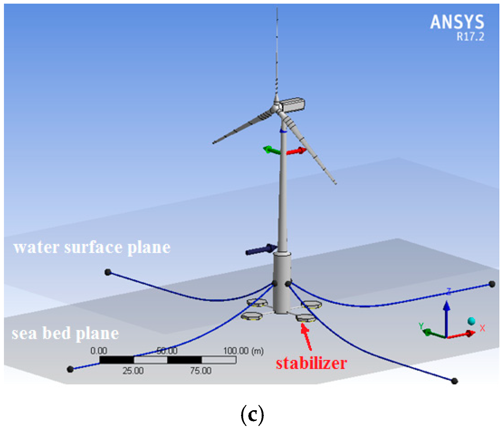
Based on the turbine parameters listed in Table 2, the numerical model of the floating turbine was developed in ANSYS Fluent. The rotating blades were modelled by establishing an additional rotating domain in the large domain already defined. In the rotating domain, the blades were defined as moving walls. Then the rotating speed of the blades is defined by setting the rotational speed of the moving walls. Once the wind load acting on the rotating blades is obtained in ANSYS Fluent, it is imported into ANSYS AQWA for calculating the motions of the floating turbine before and after using the motion stabilizers. In numerical tests, three different sizes of four-wing stabilizers were developed in ANSYS AQWA. The radius of the heave plates used in the three stabilizers is R = 7, 9, and 11 m, respectively. Considering a single heave plate was tried previously [29] to limit the heave motion of spar-supported wind turbines, the numerical model of the spar-supported turbine that is equipped with a single heave plate was developed as well for comparison. The radius of the single heave plate R = 14 m. The wind turbine models used in the numerical tests are illustrated in Figure 4.
Since it was found that thinner discs can generate stronger vortices, thereby larger drag coefficient [30], all heave plates used in the stabilizers are made of thin discs. In the numerical models, the floating turbine is held at place by 4 identical catenary mooring lines. Each mooring line consists of 3 catenary sections, the details of which are listed in Table 3.
Due to the mass and additional buoyancy caused by the motion stabilizers, the parameters of the floating turbine will change more or less. The effects of different design scenarios on key turbine parameters are presented in Table 4.
Since the mean wave period is 15–20 s in extreme weather conditions in the North Sea [13], a constant water depth 50 m and wave period increasing from 4 to 20 s were considered in the numerical calculations, so that the motion stabilization capability of the new concept stabilizer can be tested over a wide range of wave period. Since the drag coefficient of heave plates has been found to have a significant influence on the response of floating structures [31], its value in the simulation calculations was carefully selected. In theory, the for a flat disc normal to a steady flow at high Reynolds number is 1.17. But the for an oscillating disc is much larger in value. Therefore, the value of was set to be 1.2 in the present simulation calculations, although its value may reach 2.0–3.5 in laboratory tests [32]. The calculation results obtained in different scenarios are shown in Figure 5. Here, the pitch and heave motions of the floating turbine are shown, as the motions in these two directions have important influences on the safety and power generation efficiency of the turbine.
From Figure 5, it is seen that both the pitch and heave movements of the floating turbine are successfully suppressed over a wide range of wave period (4–18 s) after the turbine is equipped with either a single plate or the four-wing stabilizer. Moreover, the larger the size of the wing plates, the more the motions are reduced. But in comparison, the proposed four-wing stabilizer is more effective than the single plate in motion reduction. On the one hand, this is attributed to the contribution of the four structural arms that amplifies the effect of the stabilizer. On the other hand, it is because all plate surfaces of the proposed concept stabilizer are exposed to water, which enables the stabilizer to utilize 100% of plate surfaces to create damping. By contrast, part of the surface of the single plate stabilizer is occupied by the bottom plane of the spar foundation. The reduced wet surface area results in a smaller damping force created by the single plate, and consequently less motion reduction.
Through conducting the above numerical tests, it can be concluded that the proposed concept stabilizer does show great potential to stabilize a floating wind turbine. Moreover, it performs better than the traditional single plate stabilizer in motion reduction.
4.2. Experimental Tests
Secondly, the effectiveness of the proposed concept motion stabilizer was tested experimentally. The laboratory tests were conducted in the wind–wave–current tank at Newcastle University. The tank size is 11 × 1.8 × 1.0 m. The central measurement section is 3.0 × 1.8 × 1.0 m with surrounding glass walls for facilitating observation. The testing capabilities of the tank are listed in Table 5.
The tank control and data acquisition system is shown in Figure 6a, in which the computer on the left is used to set the parameters of wind, wave, and current; the computer in the middle is used to run the LabVIEW software for wave probe data collection; and the computer on the right is used to run the Qualisys Track Manager (QTM) software with embedded motion capture triggers. The six degree of freedom (6 DoF) of movement of the floating turbine is measured using two Oqus Motion Capture cameras provided by Qualisys AB, as shown in Figure 6b. The Qualisys measurement system provides accurate position information about the movement of the turbine via two cameras. The cameras track the positions of three motion markers, and then convert the position tracking results into the 6 DoF motions via built-in software.
Based on the tank testing capabilities listed in Table 5, the offshore environments that will be simulated in the experimental tests are determined. They are listed in Table 6. In reality, wave height and tidal current speed are correlated to the offshore wind speed. Accordingly, both wind speed and tidal current speed listed in Table 6 are small in value, as the maximum wave height that can be simulated in the wind–wave–current tank is only 0.2 m.
Initially, a small three-bladed wind turbine was made in the hydro-laboratory of Newcastle University for conducting the experimental test of the new concept stabilizer. It is shown in Figure 7. In this model, the turbine rotor is driven by a DC motor installed in the nacelle.
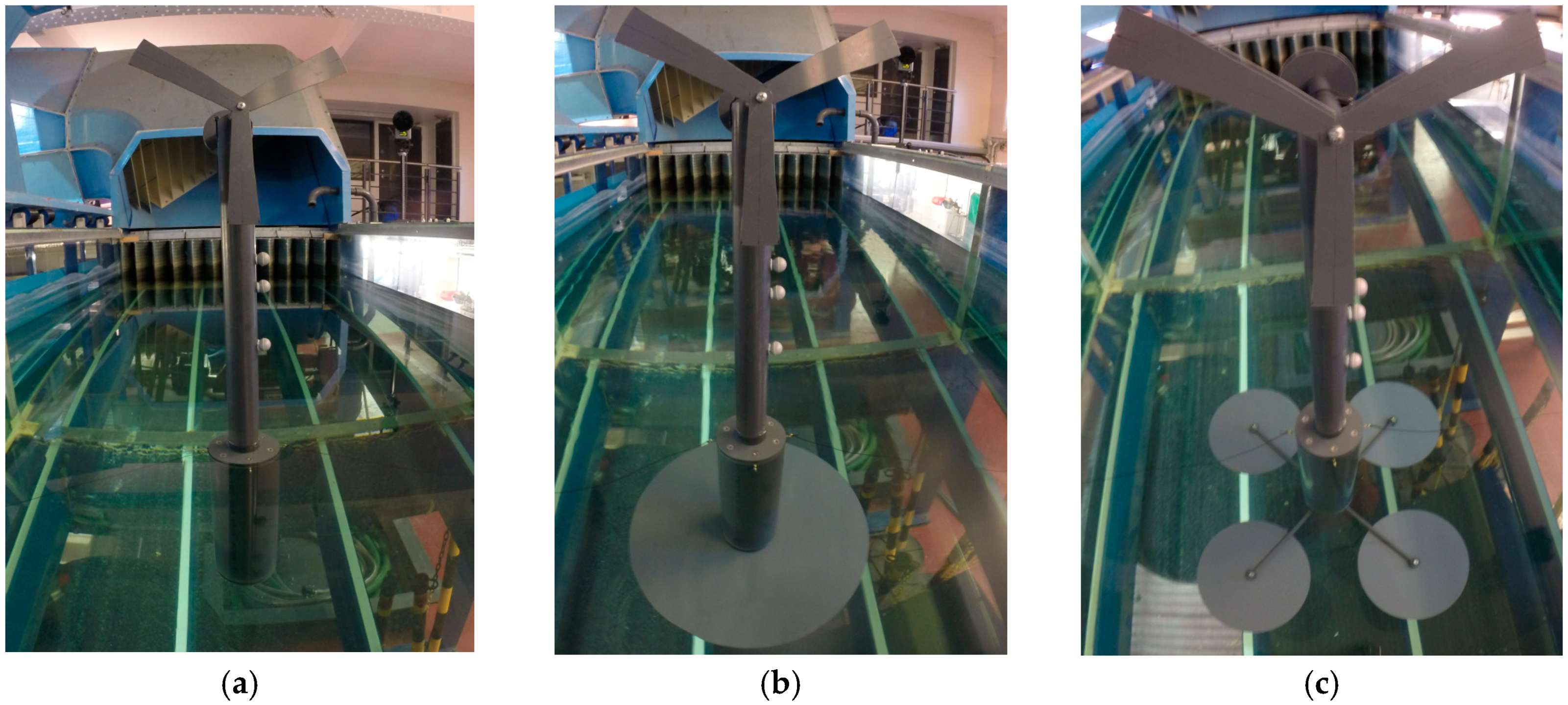
However, the early testing results has shown that the motions of the turbine were dominated mainly by waves. The effectiveness of the proposed concept stabilizer on overcoming the influences of inconsistent wind and tidal current loads cannot be successfully exhibited due to the small wind and tidal current speeds as well as the slim blade and tower structures of the turbine. For this reason, an “amplified” wind turbine, with “wide” blades, “bulky” tower and “larger” floating foundation, was made again in the laboratory in order to investigate the effectiveness of the proposed concept stabilizer under various combined wind, wave, and tidal current loading conditions. The “amplified” turbine is illustrated in Figure 8.
Then, the turbine was tested respectively before and after it was equipped with the stabilizers. The pitch and heave motions of the turbine, which are measured under different loading conditions, are shown in Figure 9.
From Figure 9, it is clearly seen that the stabilizers do successfully limit the pitch and heave movements of the spar-supported floating turbine with the exception of only two pitch motion measurement results obtained when the wave period is 2 s in Figure 9c and 1.5 s in Figure 9e. These two exceptional results might be caused by the uncertainties in the tests. The reasons of the uncertainties are complex. For example, after one test is completed, the second test should not be started immediately until the kinetic energy remaining in water fully dissipates. Otherwise, the remained kinetic energy will affect the accuracy of the new test. However, it is difficult to guarantee this in practical tests because the time waiting for water to completely calm down is different when different offshore loading conditions are simulated. In addition, due to the small size of the tank it is difficult to avoid the influences of the waves reflected from the end of the tank. In order to minimize this influence, only those data collected before the waves were reflected were used in assessment. That may affect the reliability of the assessment to certain extent. Finally, the assessment was based on observation, which may introduce errors especially when the wave period is short. Despite the influences of these uncertainties, the proposed concept stabilizer performs much better than the single plate does in stabilizing the floating turbine over the most range of wave periods from 1.5 to 4 s, particularly under the combined wind–wave–current loading conditions. As the combined wind–wave–current loading conditions are more similar to the real offshore environments that the floating turbine may experience, the results measured under such conditions are more indicative of the effectiveness of the proposed concept stabilizer in practical operation. So, it can be concluded that the proposed concept stabilizer is superior to the single plate in stabilizing floating wind turbines.
In order to better understand the respective influences of wind, wave, and current loads on the movement of a floating turbine, the laboratory testing results shown in Figure 9 were re-organized in Figure 10.
From Figure 10, it has been found that besides the influence of sea waves, wind and tidal current also have big influence on the pitch motions of a floating turbine whether or not the turbine is equipped with a stabilizer. This observation is in agreement with the research conclusion obtained in [33]. By contrast, the heave motion of the floating turbine is dominated only by sea waves, and the influences of wind and tidal current on the heave motion of the turbine are small and ignorable.
5. Conclusions
In order to explore a viable solution for stabilizing floating wind turbines in relatively shallow water, a new concept motion stabilizer is studied in this paper. Thanks to the smaller size of the wing plates, the proposed concept stabilizer is easier to fabricate, install, repair, and replace, thus is more ideal for site application. From the research reported above, it can be concluded that the proposed concept stabilizer is more effective than the traditional single plate in stabilizing floating wind turbines attribute to its larger wet surface area and the unique contribution of its four structural arms. In addition, both numerical and experimental tests have shown that all the three—wind, waves, and tidal current have influences on the pitch motion of a floating wind turbine. However, the heave motion of the floating turbine is dominated mainly by sea waves. The influences of wind and tidal current on the heave motion of the turbine is small and ignorable. Finally, it is worth noting that the proposed concept stabilizer is equally applicable to stabilizing the floating wind turbines that are supported by other types of floating foundations. Following the study depicted above, more research is still required to further improve the design of the stabilizer. For example, it has been found that the geometric design of heave plates and their installation position on the spar can also affect the hydrodynamic responses of a floating turbine. The relevant investigation has not been conducted in this paper. In addition, the fatigue loads acting on the connections of the proposed concept stabilizer are critical for its reliability and durability. These loads and their influences will be studied as well in the future research.
Author Contributions
Conceptualization, W.Y.; methodology and numerical testing, W.T.; experimental testing, O.H.; writing—review and editing, W.Y. and W.T.; funding acquisition, Z.P., K.W. and X.T.
Funding
The work reported in this paper was supported by the UK EPSRC fund (EP/R021503/1), the Open Research Project of State Key Laboratory of Mechanical System and Vibration (MSV201504), Chinese Natural Science Foundation (11632011), and Hunan Provincial Natural Science Foundation (2017JJ4017 and 2018JJ4048).
Conflicts of Interest
The authors declare no conflict of interest.
References
- UK Offshore Deal ‘in Summer’. Available online: https://renews.biz/33498/uk-offshore-deal-in-summer (accessed on 16 May 2019).
- The European Offshore Wind Industry—Key Trends and Statistics. 2015. Available online: https://www.ewea.org/fileadmin/files/library/publications/statistics/EWEA-European-Offshore-Statistics-2015.pdf (accessed on 16 May 2019).
- Clean Energy Pipeline. Offshore Wind Project Cost Outlook. 2014. Available online: http://www.cleanenergypipeline.com/Resources/CE/ResearchReports/Offshore%20Wind%20Project%20Cost%20Outlook.pdf (accessed on 16 May 2019).
- Tavner, P. Offshore Wind Turbine: Reliability, Availability and Maintenance; IET: London, UK, 2012; ISBN 978-1-84919-229-3. [Google Scholar]
- Dinh, V.N.; McKeogh, E. Offshore Wind Energy: Technology Opportunities and Challenges: Energy and Geotechnics. In Proceedings of the 1st Vietnam Symposium on Advances in Offshore Engineering (VSOE 2018), Hanoi, Vietnam, 1–3 November 2018. [Google Scholar] [CrossRef]
- Dinh, V.N.; Basu, B. On the modeling of spar-type floating offshore wind turbines. Key Eng. Mater. 2013, 569–570, 636–643. [Google Scholar] [CrossRef]
- Hywind: Siemens and StatoilHydro Install First Floating Wind Turbine. 2009. Available online: https://www.siemens.com/press/en/presspicture/?press=/en/presspicture/2009/renewable_energy/ere200906064-01.htm (accessed on 16 May 2019).
- Dominique, R.; Christian, C.; Alexia, A.; Alla, W. WindFloat: A floating foundation for offshore wind turbines. J. Renew. Sustain. Energy 2010, 2, 033104. [Google Scholar]
- World’s First Floating Wind Farm has Started Production. Available online: https://www.statoil.com/en/news/worlds-first-floating-wind-farm-started-production.html (accessed on 17 May 2019).
- Fukushima Offshore Wind Consortium. Available online: http://www.fukushima-forward.jp/english (accessed on 17 May 2019).
- WindFloat Atlantic Project. Available online: https://www.repsol.com/en/sustainability/climate-change/new-energy-solutions/windfloat/index.cshtml (accessed on 17 May 2019).
- France Awards Contracts to 48 MW Floating Wind Pilots. Available online: https://renewablesnow.com/news/france-awards-contracts-to-48-mw-floating-wind-pilots-545682/ (accessed on 17 May 2019).
- Dogger Bank Wind Farms. Available online: https://doggerbank.com (accessed on 17 May 2019).
- Yang, W.; Tian, W.; Peng, Z.; Wei, K.; Feng, Y.; Qiu, Y. Numerical research of an effective measure for stabilizing floating wind turbines in shallow water. In Proceedings of the 7th International Conference on Renewable Power Generation, Copenhagen, Denmark, 26–27 September 2018. [Google Scholar]
- North Sea. Available online: https://en.wikipedia.org/wiki/North_Sea (accessed on 17 May 2019).
- Goupee, A.J.; Koo, B.J.; Kimball, R.W.; Lambrakos, K.F.; Dagher, H.J. Experimental comparison of three floating wind turbines concepts. ASME J. Offshore Mech. Arct. Eng. 2014, 136, 020906-1–020906-9. [Google Scholar] [CrossRef]
- PelaStar Cost of Energy: A Cost Study of the PelaStar Floating Foundation System in UK Waters. Available online: https://s3-eu-west-1.amazonaws.com/assets.eti.co.uk/documents/PelaStar-LCOE-Paper-21-Jan-2014.pdf?mtime=20160912135530 (accessed on 17 May 2019).
- Wind Power Monthly, Sway Floating Test Model Sinks off Norwegian Coast. November 2011. Available online: https://www.windpowermonthly.com/article/1107100/sway-floating-test-model-sinks-off-norwegian-coast (accessed on 17 May 2019).
- Hazim, N.; Karl, S. Control Methods for Reducing Platform Pitching Motion of Floating Wind Turbines. Available online: http://proceedings.ewea.org/offshore2009/allfiles2/189_EOW2009presentation.pdf (accessed on 6 March 2019).
- Tran, T.T.; Kim, D.H. The platform pitch motion of floating offshore wind turbine: A preliminary unsteady aerodynamic analysis. J. Wind Eng. Ind. Aerodyn. 2015, 142, 65–81. [Google Scholar] [CrossRef]
- Namik, H.; Stol, K. Performance analysis of individual blade pitch control of offshore wind turbines on two floating platforms. Mechatronics 2011, 21, 691–703. [Google Scholar] [CrossRef]
- Colwell, S.; Biswajit, B. Tuned liquid column dampers in offshore wind turbines for structural control. Eng. Struct. 2009, 31, 358–368. [Google Scholar] [CrossRef]
- Lackner, M.A.; Rotea, M.A. Structural control of floating wind turbines. Mechatronics 2011, 21, 704–719. [Google Scholar] [CrossRef]
- Si, Y.; Karimi, H.R.; Gao, H. Modeling and parameter analysis of the OC3-Hywind floating wind turbine with a tuned mass damper in nacelle. J. Appl. Math. 2013, 679071. [Google Scholar] [CrossRef]
- Haines, C.S.; Lima, M.D.; Li, N.; Spinks, G.M.; Foroughi, J.; Madden, J.D.; Kim, S.H.; Fang, S.; de Andrade, M.J.; Göktepe, F.; Göktepe, Ö. Artificial muscles from fishing line and sewing thread. Science 2014, 343, 868–872. [Google Scholar] [CrossRef] [PubMed]
- Li, Y.; Wu, Z. Stabilization of floating offshore wind turbines by artificial muscle based active mooring line force control. In Proceedings of the 2016 American Control Conference (ACC), Boston, MA, USA, 6–8 July 2016. [Google Scholar]
- American Physical Society’s Division of Fluid Dynamics, The Secret of Dragonflies’ Flight. November 2014. Available online: https://www.sciencedaily.com/releases/2014/11/141124074735.htm (accessed on 17 May 2019).
- Faltinsen, O.M. Sea Loads on Ships and Offshore Structures (Cambridge Ocean Technology Series); Cambridge University Press: Cambridge, UK, 1993. [Google Scholar]
- Subbulakshmi, A.; Sundaravadivelu, R. Heave damping of spar platform for offshore wind turbine with heave plate. Ocean Eng. 2016, 121, 24–36. [Google Scholar] [CrossRef]
- Tao, L.; Molin, B.; Scolan, Y.M.; Thiagarajan, K. Spacing effects on hydrodynamics of heave plates on offshore structures. J. Fluids Struct. 2007, 23, 1119–1136. [Google Scholar] [CrossRef]
- Tian, X.; Tao, L.; Li, X.; Yang, J. Hydrodynamics coefficients of oscillating flat plates at 0.15≤KC≤3.15. J. Mar. Sci. Technol. 2017, 22, 101–113. [Google Scholar] [CrossRef]
- Brown, A.; Thomson, J.; Rusch, C. Hydrodynamic coefficients of heave plates with application to wave energy conversion. IEEE J. Ocean. Eng. 2018, 43, 983–996. [Google Scholar] [CrossRef]
- Nguyen, H.X.; Basu, B.; Dinh, V.N. Numerical investigation of wave-current interaction by using smoothed particle hydrodynamics. In Proceedings of the 1st Vietnam Symposium on Advances in Offshore Engineering (VSOE 2018), Hanoi, Vietnam, 1–3 November 2018. [Google Scholar] [CrossRef]
Figure 1.
Influence of water depth on the motion of a floating wind turbine [14].
Figure 1.
Influence of water depth on the motion of a floating wind turbine [14].

Figure 2.
State-of-the-art of some existing floating wind turbines.

Figure 3.
Schematic diagram of the proposed concept motion stabilizer.

Figure 4.
Wind turbine models used in numerical tests—(a) before using any stabilizer; (b) using a single plate; and (c) using a four-wing stabilizer.
Figure 4.
Wind turbine models used in numerical tests—(a) before using any stabilizer; (b) using a single plate; and (c) using a four-wing stabilizer.


Figure 5.
(a) Pitch and (b) heave motions obtained in numerical tests.

Figure 6.
Tank control and data acquisition system. (a) Qualisys control and measurement system and (b) Oqus motion capture camera
Figure 6.
Tank control and data acquisition system. (a) Qualisys control and measurement system and (b) Oqus motion capture camera
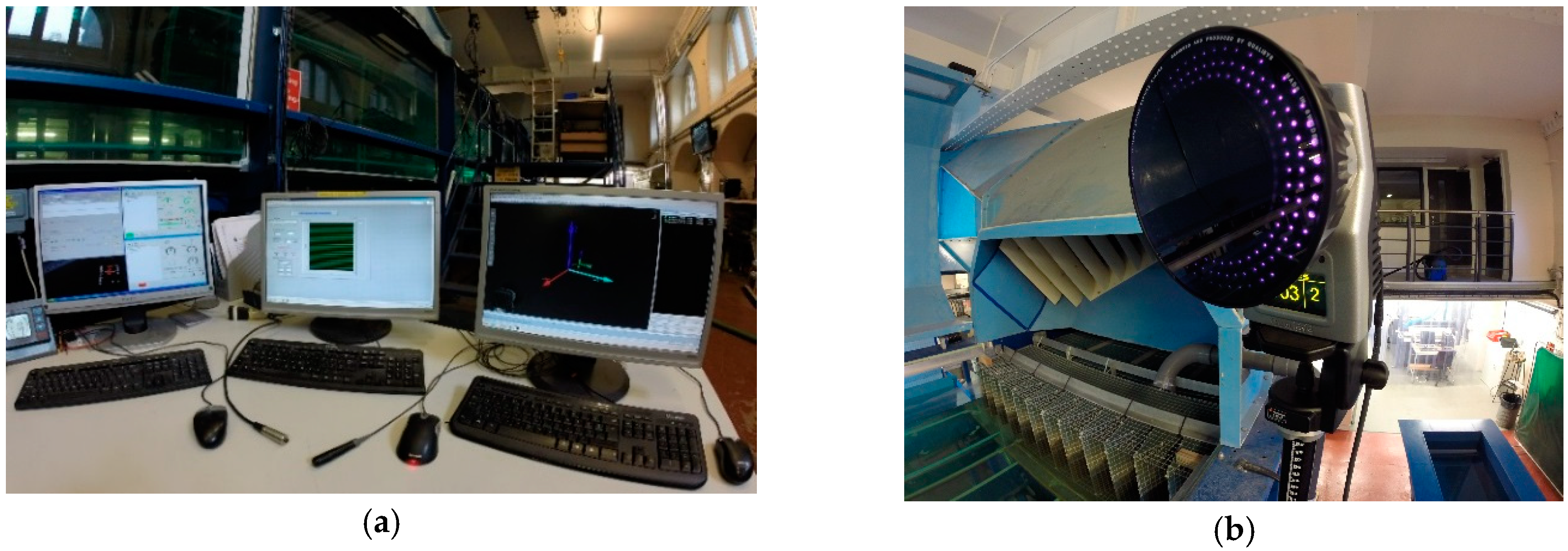
Figure 7.
Initial physical model of the wind turbine.

Figure 8.
“Amplified” turbine used in experimental tests—(a) without using a stabilizer; (b) using a single plate; and (c) using a four-wing stabilizer.
Figure 8.
“Amplified” turbine used in experimental tests—(a) without using a stabilizer; (b) using a single plate; and (c) using a four-wing stabilizer.

Figure 9.
Measured pitch and heave motions of the floating wind turbine. (a) Pitch under pure wave conditions; (b) heave under pure wave conditions; (c) pitch under wave–current conditions; (d) heave under wave–current conditions; (e) pitch under wind–wave–current conditions; and (f) heave under wind–wave–current conditions.


Figure 10.
Respective influences of wind, wave, and current loads on the motions of the turbine. (a) Pitch, supported by spar without using stabilizer; (b) heave, spar without using stabilizer; (c) pitch, spar using a single plate stabilizer; (d) heave, spar using a single plate stabilizer; (e) pitch, spar using the new concept of stabilizer; and (f) heave, spar using the new concept of stabilizer.


Table 1.
Brief review of existing floating wind turbines.
| Concept | Target Water Depth | Current Status | Type of Supporting Platform |
|---|---|---|---|
| Hywind | Prototype, 220 m Scotland, 95–120 m | In operation | Spar |
| Sway | Target, 60–300 m 1:6 scale prototype, 25 m | Prototype sank in 2011 | |
| Fukushima Hamakaze | 120 m | In operation | |
| WindFloat | Prototype, 40–50 m Portugal project, 100 m | Prototype is in operation | Semi-submersible floater (SSF) |
| Fukushima Mirai | >150 m | In operation | |
| Fukushima Shimpuu | 120 m | In operation | |
| Blue H | 113 m | In operation | Tension leg platform (TLP) |
| PelaStar | >50 m | In plan |
Table 2.
Parameters of offshore wind turbine modelled V164-8.0.
| Parameter | Value/Property |
|---|---|
| Rotor orientation | Upwind |
| Rotor configuration | 3 blades |
| Control | Variable speed, individual pitch control |
| Drivetrain | Permanent magnet direct drive |
| Rotor diameter | 164 m |
| Length of blade | 80 m |
| Hub height | 107 m |
| Cut-in wind speed | 4 m/s |
| Cut-out wind speed | 25 m/s |
| Rotor speed | 6.3—10.5 rpm |
| Nacelle | 20 (L) × 7.5 (W) × 8 (H) m |
| Tower diameter | Not available, 5–7.7 m in the numerical model |
| Rotor mass, excluding hub | 105,000 kg |
| Nacelle mass, including hub | 390,000 kg |
| Tower mass | Site dependent, 558,000 kg in the numerical model |
Table 3.
Parameters of the catenary mooring lines.
| Parameters | Catenary Section 1 | Catenary Section 2 | Catenary Section 3 |
|---|---|---|---|
| Section length (m) | 80 | 70 | 50 |
| Mass per unit length (kg/m) | 150 | 120 | 170 |
| Equivalent CSA (m2) | 0.01 | 0.01 | 0.01 |
| Stiffness, EA (N) | 600,000,000 | 900,000,000 | 600,000,000 |
| Maximum tension (N) | 7,500,000 | 7,500,000 | 7,500,000 |
| Added mass coefficient | 1.0 | 1.0 | 1.0 |
| Transverse drag coefficient | 1.0 | 1.0 | 1.0 |
| Equivalent diameter (m) | 0.1 | 0.1 | 0.1 |
| Longitudinal drag coefficient | 0.025 | 0.025 | 0.025 |
Table 4.
The parameters of the floating turbine systems in different research scenarios.
| Parameters | Floating Turbine that is Supported by | ||||
|---|---|---|---|---|---|
| Spar without Using Any Stabilizer | With a Single Heave Plate, R = 14 m | With a Four-Wing Stabilizer, R = 7 m | With a Four-Wing Stabilizer, R = 9 m | With a Four-Wing Stabilizer, R = 11 m | |
| Total Mass of the Turbine (kg) | 6,008,382 | 6,780,537 | 7,312,667 | 8,136,983 | 9,166,360 |
| Centre of Gravity (m) | −24.8 | −27.0 | −28.9 | −29.7 | −32.0 |
Table 5.
Testing capabilities of the wind–wave–current tank.
| Current Speed | Up to 1 m/s |
| Wind Speed | Up to 20 m/s |
| Wave Period | 0.8–4 s |
| Wave Height | 0.02–0.2 m |
| Wave Spectrum | Pierson–Moskowitz, JONSWAP, Bretschneider, Neumann |
Table 6.
Offshore environments simulated in the wind–wave–current tank.
| Loading Condition | Wave Period (s) | Wave Amplitude (m) | Current Speed (m/s) | Wind Speed (m/s) |
|---|---|---|---|---|
| Pure wave | 1.50 | 0.20 | – | – |
| 2.00 | 0.20 | – | – | |
| 3.00 | 0.20 | – | – | |
| 4.00 | 0.20 | – | – | |
| Wave–current | 1.50 | 0.20 | 0.10 | – |
| 2.00 | 0.20 | 0.10 | – | |
| 3.00 | 0.20 | 0.10 | – | |
| 4.00 | 0.20 | 0.10 | – | |
| Wind–wave–current | 1.50 | 0.20 | 0.10 | 2.50 |
| 2.00 | 0.20 | 0.10 | 2.50 | |
| 3.00 | 0.20 | 0.10 | 2.50 | |
| 4.00 | 0.20 | 0.10 | 2.50 |
© 2019 by the authors. Licensee MDPI, Basel, Switzerland. This article is an open access article distributed under the terms and conditions of the Creative Commons Attribution (CC BY) license (http://creativecommons.org/licenses/by/4.0/).
Share and Cite
MDPI and ACS Style
Yang, W.; Tian, W.; Hvalbye, O.; Peng, Z.; Wei, K.; Tian, X. Experimental Research for Stabilizing Offshore Floating Wind Turbines. Energies 2019, 12, 1947. https://doi.org/10.3390/en12101947
AMA Style
Yang W, Tian W, Hvalbye O, Peng Z, Wei K, Tian X. Experimental Research for Stabilizing Offshore Floating Wind Turbines. Energies. 2019; 12(10):1947. https://doi.org/10.3390/en12101947
Chicago/Turabian StyleYang, Wenxian, Wenye Tian, Ole Hvalbye, Zhike Peng, Kexiang Wei, and Xinliang Tian. 2019. "Experimental Research for Stabilizing Offshore Floating Wind Turbines" Energies 12, no. 10: 1947. https://doi.org/10.3390/en12101947
Note that from the first issue of 2016, this journal uses article numbers instead of page numbers. See further details here.