Article

Slip Control of a Squirrel Cage Induction Generator Driven by an Electromagnetic Frequency Regulator to Achieve the Maximum Power Point Tracking

by
Thales Ramos
1,*,
Manoel F. Medeiros Júnior
2,
Ricardo Pinheiro
2 and
Arthur Medeiros
1
1
Federal Institute of Education, Science and Technology of Rio Grande do Norte, Natal 59015-000, Brazil
2
Federal University of Rio Grande do Norte, Natal 59078-970, Brazil
*
Author to whom correspondence should be addressed.
Energies 2019, 12(11), 2100; https://doi.org/10.3390/en12112100
Submission received: 26 February 2019 / Revised: 16 May 2019 / Accepted: 17 May 2019 / Published: 1 June 2019
(This article belongs to the Special Issue Distributed and Renewable Power Generation 2018)

Abstract

:
A new topology was recently developed to drive generators, aiming to avoid power electronic devices directly connected to the grid, and making possible the hybridization of the wind power with other sources. The system is composed by an induction machine with rotor in squirrel cage, and a rotating armature endowed with a three-phase winding that may be fed by a secondary source. The previous purpose was to convert a variable velocity imposed by the wind turbine to the armature in a constant velocity to be developed by the cage rotor, driving a shaft of synchronous generator. This article proposes the use of an induction generator instead of a synchronous one in order to explore the maximum available wind energy (MPPT). The simulation results show that the proposed topology is viable and supports both variations in wind speed and disturbances in power grid.

1. Introduction

Human necessity for electric power grows continually. This way, the use of renewable resources which requires minimal impacts to environment is strongly desirable. Among renewables mentioned by [1] study wind and hydraulic resources are predominant. Data obtained from [2] shows that the growth of wind energy in the last years is worldwide the most significant.
Nowadays, there are several topologies of wind generators, each one presenting advantages and disadvantages. In [3], most used topologies in wind farms are presented. They are based in synchronous machines or in induction machines, either with wounded rotor or with squirrel cage. Except rare cases, they are coupled to the wind turbine by means of a gearbox and are connected to the grid by means of electronic converters. New topologies, however, have been proposed in recent years, looking for reducing effects relative to power quality or for optimizing generated power, among others. For example, articles [4,5] present a generation system based on two double fed induction machines in cascade. One of them achieves the whole control whereas the other is responsible for power generation. Another concept is a new generator using permanent magnet addressing a large number of poles as proposed in [6], with the main objective of eliminating necessity of gearbox. More topologies based on permanent magnet are presented in [7].
Considering the increasing use of renewables as well the search for more efficient generation topologies, some efforts have also been carried out with the aim of integrating different resources in a hybrid generation scheme. In this sense, the proposal presented in [8] consists in a hybrid system composed by a wind turbine, and a micro turbine driven by vapor produced by solar h eaters. The results of a study showing the effects of variation in solar intensity and wind velocity in the performance of a hybrid isolated generation system is presented in [9]. Some other studies present alternatives to hybridization of solar and wind generations [10,11,12].
Following this trend, a new topology was recently developed to drive generators, aiming to avoid power electronic devices directly connected to the grid, and making possible the hybridization of the wind power source with another one. This system is named Electromagnetic Frequency Regulator (EFR) and consists of an induction machine with rotor in squirrel cage and a rotating armature endowed with a three-phase winding that may be fed by a secondary source [13,14]. Although the term “stator” is proper for induction machines, it will not be used here because this term suggests something stationary (from Latin). The authors of references [13,14] preferred to designate it as an asynchronous rotor because the other rotor would drive a synchronous machine and, therefore, would rotate at a synchronous speed. Since in this work it is not necessary to classify the parts in relation to a synchronous speed, since the adopted generator is an induction machine, the authors preferred to designate the parts of the EFR simply as armature (connected to the gearbox) and rotor (connected to the generator shaft). The main function of the EFR is to convert a variable speed imposed by the wind turbine to the armature in a desirable speed to be developed by the cage rotor.
Another generation topology similar to that here proposed is presented in [15]. It also consists of a squirrel cage induction machine in which there is no stationary part, i.e., both parts are rotating. The device presented in reference [15] is named Electromagnetic Coupler. Articles [13,14,15] still have the similarity of the use of a synchronous generator connected to high speed shaft of the induction machine. There are two main differences between the devices. Whereas the EFR uses the cage connected to the synchronous generator, the Electromagnetic Coupler has the cage connected to the shaft of the gearbox. Furthermore, the EFR’s inverter is DC/AC and needs to be connected to an external DC power source, whereas the structure with Electromagnetic Coupler uses a back-to-back converter that receives power from the grid. The advantage of both topologies is the mechanical decoupling between the wind turbine and the generator. However, the EFR like presented in [13,14] is not as efficient as the Electromagnetic Coupler of [15], for driving a synchronous generator, because the EFR is not associated with control devices necessary to allow a reasonable range of active and reactive power generation. This way, the topology present in this article uses an EFR, but not driving a synchronous generator.
This article presents a new application for the EFR: instead of using a generator with constant speed (synchronous), coupled to its shaft, the use of an induction generator will be explored, thus enabling the tracking of the point of maximum power extraction of the wind (MPPT). This may be achieved by imposing to the generator the torque corresponding to the maximum wind power extraction, and so defining the reference velocity to be controlled by the EFR.
An analysis in steady state was carried out in order to determine the contributions to the generated power from the wind source and from the other source. Dynamic simulations are introduced to evaluate the robustness of the new topology in the face of events such as wind disturbances like steps, ramp, turbulence and gust as well as the ability to not disconnect after short circuits, according the ride-through curves of some countries.

2. Mathematical Modeling of the System

2.1. Horizontal Axis Wind Turbine

The extraction of mechanical power from the winds for a horizontal axis wind turbine is determined by [16,17,18]:
P t   =   1 2 ρ π R 2 C p ( λ , β ) V w 3 ,
where ρ is air density, R is the radius of the blade, C p is the power coefficient which depends upon the tip-speed ratio ( λ ) and blade pitch-angle ( β ), and V w is the wind speed. The tip-speed ratio is calculated by
λ   =   ω t R V w ,
where ω t is the turbine angular speed. The power coefficient ( C p ) describes the aerodynamic performance of the turbine whose theoretical maximum value is known as the Betz limit and is equal to 0.593. Each wind turbine has its own power coefficient curve. For the purposes of this work the coefficient defined in (3) was adopted [19]:
C p ( λ , β )   =   0.73 ( 151 λ i 0.58 β 0.02 β 2.14 13.2 ) e 18.4 λ i ,
where
λ i   =   ( 1 λ 0.02 β + 0.003 β 3 + 1 ) 1
and β is the blade pitch angle in degrees.
Figure 1 shows the curves of the power coefficient as a function of tip-speed ratio ( λ ) and for some blade pitch angle ( β ) values. The maximum value of the power coefficient ( C p _ m a x ) is approximately 0.441, corresponding to λ = λ o p t = 7.206 , when the blade pitch angle is at its minimum ( β = 0 ° ).
The mechanical torque produced by the wind turbine can be obtained from the following equation:
T t =   P t ω t   =   1 2 ρ π R 3 C p ( λ , β ) λ V w 2 .

2.2. Induction Generator

Considering the simplifying assumptions presented in [20], the voltage equations of a squirrel cage induction generator can be expressed as [21]:
v d 1 g   =   r 1 g i d 1 g   ω e λ q 1 g +   d d t λ d 1 g ,
v q 1 g   =   r 1 g i q 1 g +   ω e λ d 1 g +   d d t λ q 1 g ,
v d 2 g = 0 =   r 2 g i d 2 g ( ω e   P g 2 ω m ) λ q 2 g +   d d t λ d 2 g ,
v q 2 g = 0 =   r 2 g i q 2 g +   ( ω e   P g 2 ω m ) λ d 2 g +   d d t λ q 2 g ,
where v d 1 g , v q 1 g are the terminal voltages in d and q axes at the stator, r 1 g is the stator resistance, i d 1 g , i q 1 g are the electrical currents in the d and q axes at the stator, ω e is the synchronous angular frequency, i.e., the grid voltage pulsation, λ d 1 g , λ q 1 g are the flux linkages in the d and q axes at the stator, v d 2 g , v q 2 g are the rotor voltages in d and q axes, r 2 g is the rotor resistance, i d 2 g , i q 2 g are the rotor currents in the d and q axes, P g is the number of poles of the induction generator, ω m is the angular speed of rotor shaft and λ d 2 g , λ q 2 g are the flux linkages in the d and q axes of the rotor.
The relationships between the electric currents and the flux linkages are expressed by:
λ d 1 g   =   L 11 g i d 1 g +   L 12 g i d 2 g ,
λ q 1 g   =   L 11 g i q 1 g +   L 12 g i q 2 g ,
λ d 2 g   =   L 22 g i d 2 g +   L 12 g i d 1 g ,
λ q 2 g   =   L 22 g i q 2 g +   L 12 g i q 1 g ,
where:
L 11 g =   L s 1 g   L m 1 g ,
L 12 g =   3 2 L m g ,
L 22 g =   L s 2 g   L m 2 g ,
where L s 1 g is the self-inductance of any stator winding, L s 2 g is the self-inductance of any rotor winding, L m 1 g is the mutual inductance between any two windings in the stator, L m 2 g is the mutual inductance between any two windings in the rotor and L m g is the maximum mutual inductance between stator and rotor windings.
The electromagnetic torque of the induction generator T e g can be obtained from:
T e g =   3 2 P g 2 ( λ d 1 g i q 1 g   λ q 1 g i d 1 g ) .
Using the convention of electric currents adopted, the numerical evaluation of Equation (17) results as a negative value.

2.3. Electromagnetic Frequency Regulator
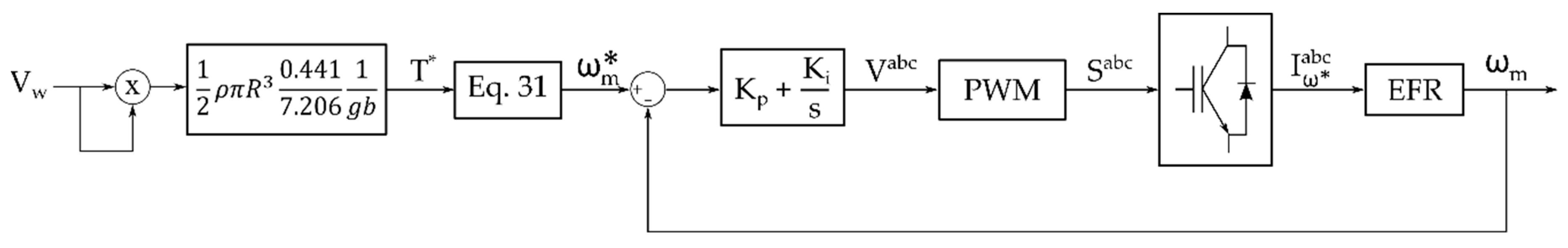
The Electromagnetic Frequency Regulator (EFR) is a system consisting of an induction machine with a squirrel cage rotor and rotating armature, as well as a frequency inverter that adjusts the electric current injected into the armature. The purpose of this system is to receive a variable angular speed (such as that of a wind turbine) and deliver a desired angular speed to the EFR’s rotor [13,14].
The conventional induction machine has as stationary element the stator (armature), housing a set of coils connected to a three-phase power grid. The innovation of the EFR is to allow the armature to rotate integrally with the wind turbine. Thus, in this system there is not a stationary part but two components that rotate with different speeds. In order to have electrical access to the rotating armature it is necessary to insert collector rings that do not normally exist in an induction machine with a rotor in a squirrel cage.
Considering that the speed of wind turbines is significantly lower than the rotating field speed required for generating voltage at the grid frequency, several topologies of wind turbines adopt the use of a gearbox. Its effect is to multiply speeds and as well to reduce torque. This component is also considered to compose the EFR-driven generation system as shown in Figure 2. The relationship between the turbine and EFR armature speed is shown in the following equation:
g b =   ω a ω t = T t T a ,
where ω a is the armature speed and T a is the armature torque.
Figure 2 shows a schematic 3D visualization, highlighting some constructive aspects of the proposed system. The shaft attached to the gearbox, which supports the collector rings which receive the power from the inverter, is also mechanically connected to the EFR armature, although this coupling is not visible in the figure.
Figure 3 presents the proposed generation system adapted from [13], replacing the synchronous generator by an induction one.
Since the objective of the EFR is to keep the rotor speed at the desired reference, it is necessary to control the frequency of the electric current injected in the armature. The armature speed added to the rotating field speed of the armature causes a rotor speed corresponding to the desired slip. This is achieved by the frequency inverter connected to the armature.
The frequency inverter needs to be supplied by a direct current source, which could be provided by a solar panel, a hydrogen cell, or even a set of smaller wind turbines, for example.
The whole development presented in this article considers that the direction of the mechanical angular speed of the armature is the same as the rotational magnetic field caused by the armature currents. This way, the resulting magnetic field speed is the sum of the mechanical speed of the armature and the speed of the rotating magnetic field caused by the electric frequency of the inverter output currents.
As sketched in Figure 2 and Figure 3, the EFR rotor and the induction generator rotor are mechanically coupled and therefore have the same mechanical speed ω m . Although the rotor speeds of both machines are the same, their slips present opposite signs. The EFR operates with positive slip, i.e., in the motor region once the speed of the rotating field is greater than the speed of the rotor, whereas the induction generator operates with negative slip, in order to generate electrical energy.
The speed of the rotating field relative to the armature is given by the difference between the absolute speed of the rotating field and the speed of the turbine, that is: ( ω e R +   P R 2 ω a )   P R 2 ω a . Thus, the voltage equations for the armature are identical to those of conventional induction machine:
v d 1 R   =   r 1 R i d 1 R   ω e R λ q 1 R +   d d t λ d 1 R ,
v q 1 R   =   r 1 R i q 1 R +   ω e R λ d 1 R +   d d t λ q 1 R ,
where v d 1 R , v q 1 R are the terminal voltages in d and q axes at the EFR’s armature, i d 1 R , i q 1 R are the electrical currents in the d and q axes at the EFR’s armature, ω e R is the inverter voltage pulsation, λ d 1 R , λ q 1 R are the flux linkages in the d and q axes at the EFR’s armature.
Regarding to rotor voltages, the rotation imposed to the armature causes an additional rotating voltage superposing the one caused by the armature currents, so that the resulting equations become:
v d 2 R   =   r 2 R i d 2 R   [ ( ω e R + P R 2 ω a )   P R 2 ω m ] λ q 2 R +   d d t λ d 2 R = 0 ,
v q 2 R   =   r 2 R i q 2 R +   [ ( ω e R + P R 2 ω a )   P R 2 ω m ] λ d 2 R +   d d t λ q 2 R = 0 ,
where v d 2 R , v q 2 R are the EFR’s rotor voltages in d and q axes, i d 2 R , i q 2 R are the EFR’s rotor currents in the d and q axes and λ d 2 R , λ q 2 R are the flux linkages in the d and q axes of the EFR’s rotor.
The relationship between the electric currents and flux linkages are the same as for a conventional induction machine.
Unlike a conventional induction machine in which only one part rotates in the EFR both the armature and the rotor are movable. Thus, two dynamic angular acceleration equations are required, one for each part.
In order to arrive at the balance equations of the EFR it is necessary to keep in mind that the electromagnetic torque is responsible for accelerating the rotor and at the same time for the deceleration of the armature. Then the armature is accelerated by the wind turbine torque and braked by the electromagnetic torque. While the EFR rotor shaft is accelerated by its electromagnetic torque, it is braked by the electromagnetic torque of the induction generator connected to the shaft. Equations (23) and (24) describe this relationship.
J Σ d ω m d t =   T e R +   T e g   K D ω m ,
J a d ω a d t =   T a   T e R   K D t ω t ,
where J Σ is the sum of the inertia of the EFR rotor with the inertia of the induction generator rotor, T e g is the electromagnetic torque of the induction generator (a negative value), J a is the inertia of the turbine added to the inertia of the rotating armature (referred to the high speed side of the gearbox), K D t is the turbine friction and T e R is the electromagnetic torque developed in the EFR that may be calculated by:
T e R =   3 2 P R 2 ( λ d 1 R i q 1 R   λ q 1 R i d 1 R ) .
In addition to dynamic equations of both machines, the power conservation principle must be considered according to:
P t + P i = P g e r + P l o s s e s ,
where P i is the power contribution delivered by the inverter, P l o s s e s are the electrical and mechanical power losses, and P g e r is the generated power. It must be pointed out that Equation (26) is used only to prove validity of results obtained by simulations.

3. Control Strategy

The generation topology of the Electromagnetic Frequency Regulator has been designed so that the EFR receives a variable speed in the armature of the machine and delivers a desired speed in the rotor shaft. Then, when connecting an induction generator to the rotor shaft it is possible to control the torque of the generator through the slip.
The electromagnetic torque of an induction generator as a function of the slip is given by the Equation (27) [22]:
T e g = 1 ω s [ n p h V 1 , e q 2 ( r 2 / s ) ( r 1 , e q + ( r 2 / s ) ) 2 + ( X 1 , e q + X 2 ) 2 ] ,
where ω s is the synchronous angular mechanical speed, n p h is the number of phases, s is the slip, X 2 is the per-phase reactance of the rotor windings and V 1 , e q , r 1 , e q and X 1 , e q can be obtained by:
V 1 , e q = | V 1 ( j X m r 1 + j ( X 1 + X m ) ) | ,
Z 1 , e q = j X m ( r 1 + j X 1 ) r 1 + j ( X 1 + X m ) ,
where V 1 is the grid phase voltage, X m is the magnetizing reactance and X 1 is the per-phase reactance of the stator windings.
According to Equations (23) and (24), by a steady state the turbine torque, the electromagnetic torque of the EFR and the electromagnetic torque of the induction generator are equal. This allows the torque throughout the system to be controlled by the slip of the induction generator.
According to Equation (5) there is only one optimal torque for each wind speed. This is achieved when the power coefficient is at its maximum value. This way it is possible to achieve the Maximum Power Point Tracking (MPPT). Thus, the desired torque for each wind speed can be calculated from Equation (5), using C p _ m a x = 0.441 and λ o p t = 7.206 , resulting in:
T * =   1 2 ρ π R 3 0.441 7.206 V w 2 g b ,
where T * is the desired torque for the system.
Entering the desired torque in Equation (27), it leads to Equation (31), having the desired slip as unknown:
T * ω s [ r 1 , e q 2 + ( X 1 , e q + X 2 ) 2 ] s * 2 + r 2 ( 2 T * ω s r 1 , e q n p h V 1 , e q 2 ) s * + T * ω s r 2 2 = 0 ,
where s * is the desired slip. Solving Equation (31) results in two real roots. The choice between the two slips should be the one with the lowest absolute value. This choice results in lower electrical current and lower reactive power, corresponding to improved system performance.
The rotational speed of the rotor shaft may be calculated from the desired slip according to [23]:
ω m * = ( 1 s * ) ω s .
Thus, if the EFR controls the rotation speed of the shaft at the desired value, the electromagnetic torque required by the induction generator will be equal to the turbine torque that delivers the maximum power for each wind speed.
Figure 4 shows the block diagram of the control used in this article whose objective is to control the frequency and the voltage supplied by the inverter to feed the EFR armature windings.

4. Results

A simulation program was developed using Scilab platform to solve the above differential and algebraic equations. A 4th order Runge-Kutta algorithm was adopted for solving time-varying equations. Although power electronic devices can provide significantly faster responses, all simulated disturbances could be controlled by slower actuation, thus in order to accelerate simulations the step size of 1 ms was preferred.
The induction machine parameters used for the EFR simulation were taken from [24] considering the same rated power of 2 MW, which is compatible to the informed rated power of turbine. The values are shown in Table 1.
The parameters used for the simulation of the induction generator are same as adopted for EFR, including the number of poles.
Finally, the simulated wind turbine parameters are presented in Table 2 below.
In relation to the data reported in [24], the turbine diameter and the nominal wind speed were adjusted to match the nominal turbine and machines power ratings.
The moment of inertia J can be obtained in terms of inertia constant H by [18]:
J =   2 H ω 0 2 S b ,
where ω 0 is rated angular speed in mechanical radians per second and S b is the volt-ampere rating.

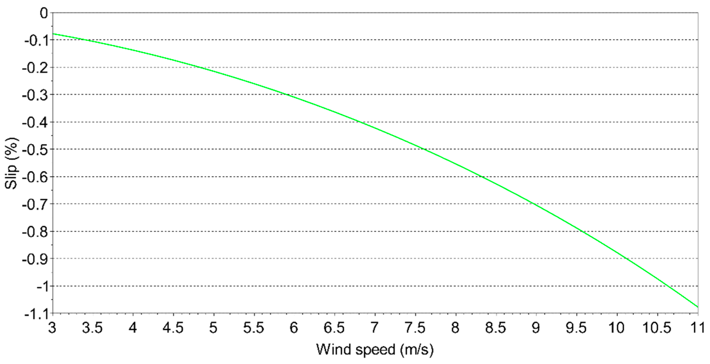
4.1. Steady State Analysis

The proposed system using the Electromagnetic Frequency Regulator was simulated in steady state for several wind speeds. The contribution of the wind turbine and the inverter to the generated power by the induction generator is shown in Figure 5.
When the wind speed reaches 11 m/s the active power in the induction generator is equal to the rated power of the machines. For wind speeds above this value, the pitch control of the wind turbine would act in order to maintain the power values at the same level.
The wind turbine design was developed so that the rated wind speed was 11 m/s, in order to better take advantage of the winds of the Brazilian Northeast since most of the time the winds have speeds between 5 m/s and 7 m/s.
Another relevant point in the graph analysis of Figure 5 is that, the maximum active power provided by the inverter is less than 18% of the rated power of the induction generator. Nevertheless, dimensioning of inverter must consider also possible stresses due to disturbances.
The slip of the induction generator for each wind speed are sketched in Figure 6.
The efficiency of the electrical generation system can be defined as the active power delivered by the generator to the power grid divided by the sum of the power supplied by the wind turbine and the power delivered by the inverter:
η =   P g e r P t + P i .
Considering just cooper losses, the efficiency is greater than 98% for any wind speed from 3 m/s up to the nominal speed. Here must be pointed out that this result was obtained using the machines of reference [24], whose data set is limited, omitting information like, e.g., iron losses.

4.2. Dynamic Analysis

The objective of this subsection is to present the dynamic performance of the proposed system during the main disturbances in a wind farm. Disturbances in the wind and in the grid connected to the generator are considered for analysis. It must be emphasized that because of very high inertias all graphics sketched in this section are thought to give an idea of the responses immediately after the disturbances, but not comprehending the whole period until steady state is reached.

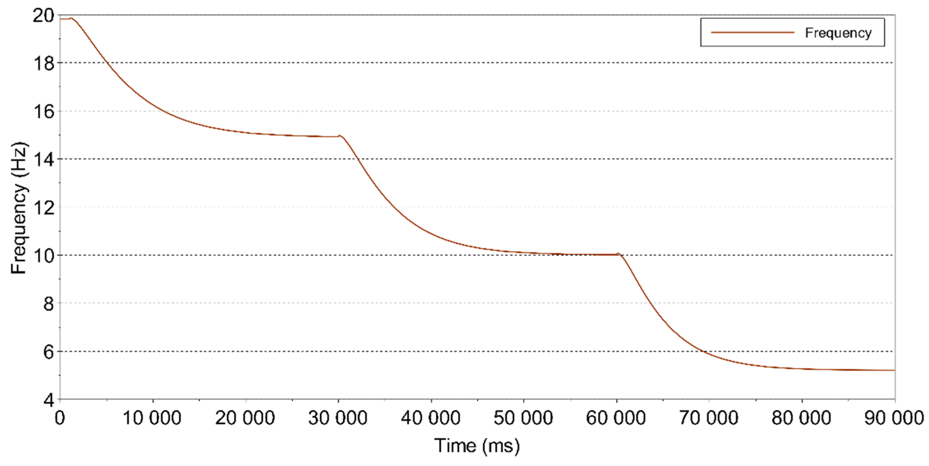
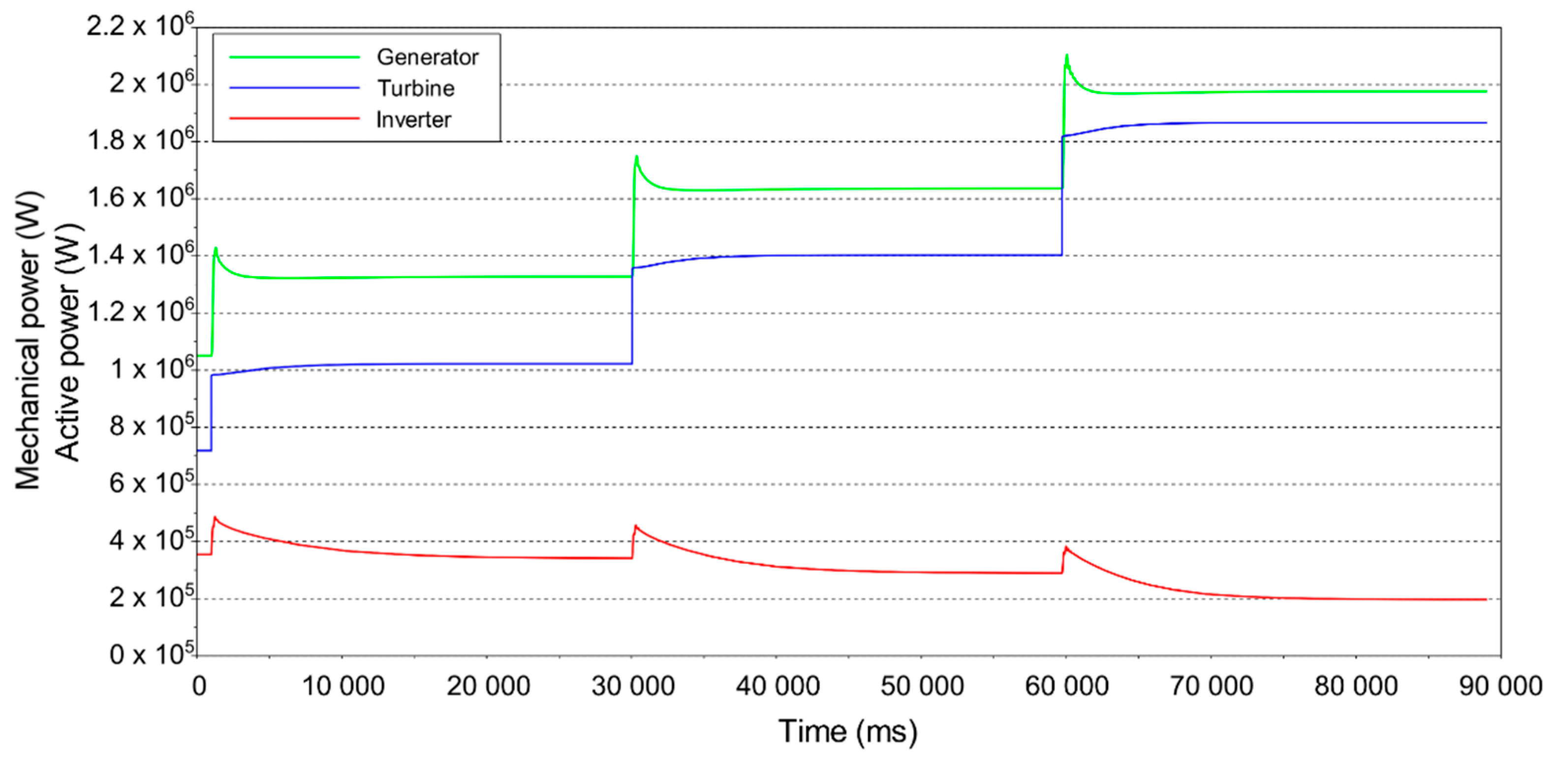
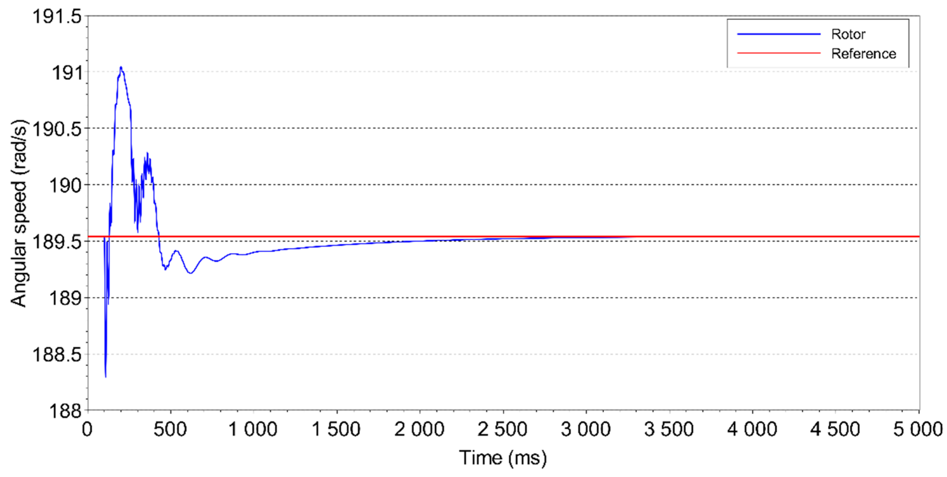
4.2.1. Step Response

The proposed system was submitted to three steps of 1 m/s in wind speed, starting from a steady state of 8 m/s. Thus, at the end of the simulation, the induction generator will be at rated power. The simulation result for the rotor speed and the desired speed is shown in Figure 7.
As described in the control strategy, the control variable that guides the speed to the desired value is the frequency of the current at the inverter output. The frequency variation due to the wind speed steps is sketched in Figure 8.
The power generated by the induction generator and its turbine and inverter contributions are presented in Figure 9.

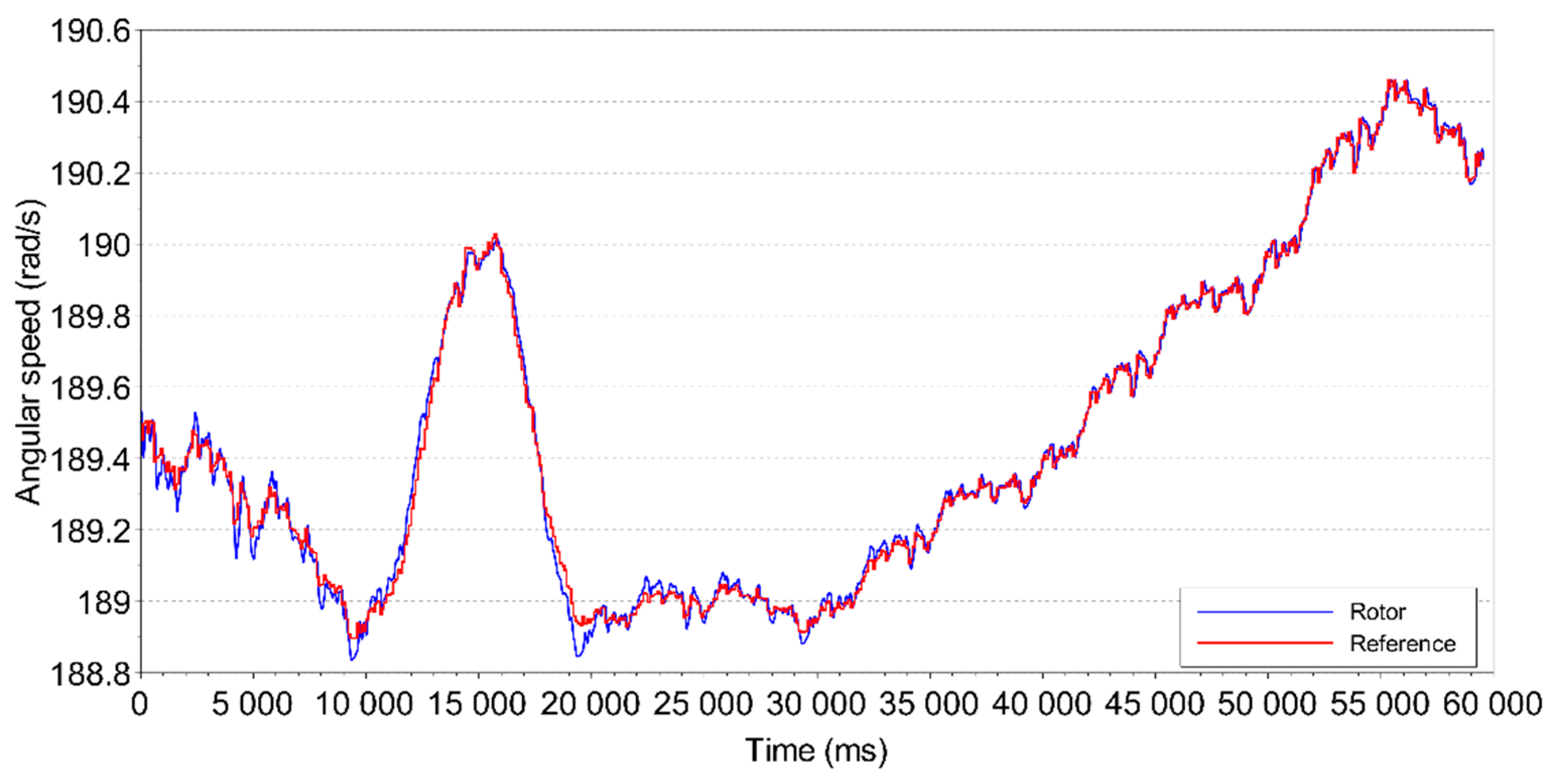
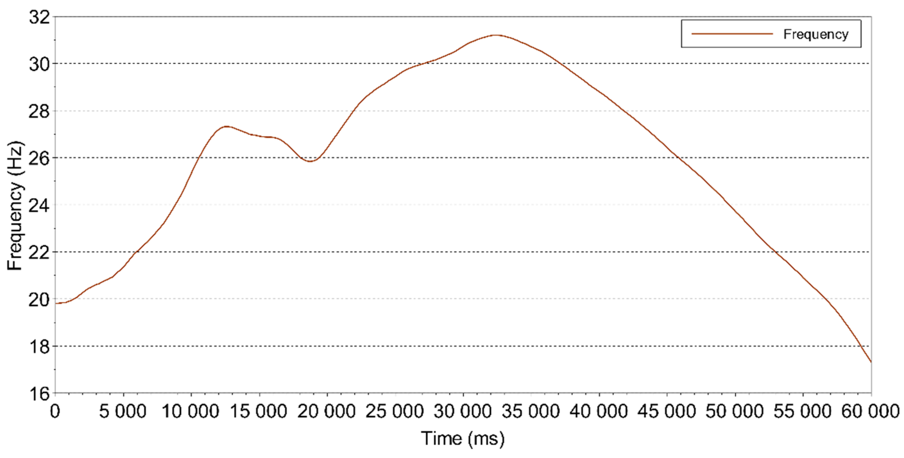
4.2.2. Wind Speed Variations

The simulated wind speed model is similar to that proposed in [24]. It is assumed that the wind speed is composed of the sum of four components:
  • The initial average value of the wind speed
  • A ramp component
  • A gust component
  • Turbulence
The simulation run was carried out in order to illustrate the response of EFR operating under normal conditions for 60 s. The applied wind speed signal is composed by all four components. The simulation starts with wind velocity equal to 8 m/s and there is a ramp with amplitude of −2.5 m/s up to 10 s. Between the instants of 10 s to 20 s there is a gust amplitude equal 4 m/s. After the instant of time equal to 30 s, there is a new ramp with amplitude of 5 m/s during 25 s. The average value component is equal to 5.5 m/s, and turbulence is present throughout the simulation. The simulated wind speed is shown in Figure 10.
The generation topology using EFR was simulated considering the wind speed shown in Figure 10. The rotational speed of the rotor and its desired speed are shown in Figure 11.
The frequency variation in time is presented in Figure 12, and the powers of generator, turbine and inverter are shown together in Figure 13, in order to make possible a comparison.

4.2.3. The Fault-Ride-Through Capability

The fault-ride-through requirements are represented through a voltage against time profile as shown in Figure 14 [25]. According to this figure, the German regulations impose the most restrictive limits for fault-ride-through capability of wind turbines, requiring that wind farms must have voltage withstand capability up to zero during 150 ms.
In order to simulate the most severe case of voltage deep, the proposed system was subjected to a stator voltage of the induction generator equal to zero for 150 ms. The disturbance occurs at the instant 100 ms and returns to the rated voltage at the instant 250 ms. The line-to-line voltage (p.u.) at the induction generator terminals representing the disturbance is presented in Figure 15.
The desired speed and the speed of the rotor shaft for the admitted voltage disturbance are shown in Figure 16.
This is the disturbance with the major speed variation in generator rotor shaft. Nevertheless, the system is able to re-establish the speed close to the desired one in less than 3 s after the return of the voltage to the rated value. As can be seen in Figure 17, the frequency of the current at the inverter output returns smoothly to the steady state, after a brief undershoot. This occurs because of inertia J a , as can be observed in the curve of Figure 18, describing the behavior of speed ω a . The voltage dip occurred at the generator stator produces a major decrease in the electromagnetic torque, leading to a fast gain in armature speed. However, a slow return to the its steady state value occurs. Note that the frequency assumes a similar behavior, in order to assure a fast return of rotor speed to the steady state (see Figure 16). Although the armature speed reaches its maximum value in a time close to 2 s, the rotor speed and the currents at the same time are already close to their steady state value. This occurs because of the compensation performed by the control action on the frequency of the inverter currents.
The currents of the induction generator and at the output of the inverter are both shown in Figure 19. As can be observed in this figure the resulting stator current of the generator during the simulated short-circuit is very high, if compared with corresponding steady-state value, whereas at the inverter, it does not happen. Another relevant aspect is that the maximum short-circuit current of the generator is almost 13 times the steady-state current, whereas the current in the inverter is only 20% higher than its steady-state value. Thus, it is unnecessary to switch off the inverter during the disturbance, as this overcurrent is compatible with the levels supported by actual devices. Therefore, extra protection for the inverter is not required, as by Rotor Side Converter (RSC) in a Doubly-Fed Induction Generator (DFIG).

5. Discussion

The results show that the topology using the Electromagnetic Frequency Regulator coupled with an induction generator is feasible in sense of exploring the maximal wind power available for the whole wind speed range, starting from the usual cut-in speed until that one corresponding to the rated power. In this way, it is possible to have a hybrid generation source using a single topology.
The generation topology proposed in this article presents some similarities with the already known Doubly-Fed Induction Generator (DFIG), as: use of gearbox, converter not dimensioned for full power, and use of an induction machine for generation. Therefore, the comparison between the two topologies is inevitable.
By the DFIG topology a back-to-back converter is required while the EFR uses a unidirectional inverter, fed by another source, and not connected to the grid. This aspect allows the use of a supplementary primary source to feed the rotating armature windings. Furthermore, no harmonic sources interact galvanically to the grid.
An apparent disadvantage of the proposed topology is the use of two induction machines instead of only one, like by DFIG, but avoiding the back-to-back converter.

6. Conclusions

Besides the advantages highlighted in previous section, the generation topology using the Electromagnetic Frequency Regulator driving an induction generator has proved to be able to withstand large variations in wind speed, like a gust, without necessity to disconnect. This topology proved also to be effective to ride-through a severe short-circuit at the induction generator terminals, even without being endowed with a crowbar, as is usual in DFIG topologies. It happens because the current at the EFR inverter output during a disturbance is not high as the current in the DFIG converter, once the inverter has no connection to the grid. These statements are consistent to the results of dynamic simulation presented in Section 4. In addition, high values of efficiency for the set of electrical machines have resulted within the wind speed operational range.
According to the steady state simulations the EFR inverter may be dimensioned for about 20% of the generator rated power. The same percentage may be applied to define the EFR armature rated power, although the rotor must be dimensioned for the total generated power. This should be considered during EFR design, resulting in economy of manufacture costs.
Concluding, all presented simulations results encourage to use the proposed system for practical applications, in sites where a supplementary source to the wind power is available.

Author Contributions

Conceptualization, M.F.M.J. and R.P.; Data curation, T.R.; Formal analysis, T.R. and M.F.M.J.; Investigation, T.R., M.F.M.J., R.P. and A.M.; Methodology, T.R., M.F.M.J., R.P. and A.M.; Project administration, M.F.M.J.; Resources, M.F.M.J. and R.P.; Software, T.R. and A.M.; Supervision, M.F.M.J. and R.P.; Visualization, T.R. and A.M.; Writing—original draft, T.R. and A.M.; Writing—review & editing, M.F.M.J.

Funding

This research received no external funding.

Conflicts of Interest

The authors declare no conflict of interest.

Nomenclature

P t Turbine mechanical power
ρ Air density
R Radius of the blade
C p Turbine Power Coefficient
V w Wind speed
λ Tip-Speed Ratio
ω t Turbine angular speed
β Blade pitch angle
T t Turbine mechanical torque
v d 1 , v q 1 Voltage in d and q axes of the stator
r 1 Stator resistance
i d 1 , i q 1 Electrical current in the d and q axes of the stator
ω e Synchronous angular frequency
λ d 1 , λ q 1 Flux linkage in the d and q axes of the stator
v d 2 , v q 2 Voltage in d and q axes of the rotor
r 2 Rotor resistance
i d 2 , i q 2 Electrical current in the d and q axes of the rotor
P Number of poles of the machine
ω m Angular speed of rotor shaft
λ d 2 , λ q 2 Flux linkage in the d and q axes of the rotor
L s 1 Self-inductance of any stator winding
L s 2 Self-inductance of any rotor winding
L m 1 Mutual inductance between any two windings in the stator
L m 2 Mutual inductance between any two windings in the rotor
L m Maximum mutual inductance between stator and rotor windings
J Inertia of the rotor
T e Electromagnetic torque
T m Mechanical torque
K D Rotor friction constant
g b Gearbox ratio
ω a Angular speed of the EFR’s armature
T a Mechanical torque at the EFR’s armature
v d 1 R , v q 1 R Voltage in d and q axes of the EFR’s armature
i d 1 R , i q 1 R Electrical current in the d and q axes of the EFR’s armature
λ d 1 R , λ q 1 R Flux linkage in the d and q axes of the EFR’s armature
ω e R Inverter voltage pulsation
v d 2 R , v q 2 R Voltage in d and q axes of the EFR’s rotor
i d 2 R , i q 2 R Electrical current in the d and q axes of the EFR’s rotor
λ d 2 R , λ q 2 R Flux linkage in the d and q axes of the EFR’s rotor
J Σ Sum of inertia of the EFR’s rotor with the inertia of induction generator rotor
T e R Electromagnetic torque developed in the EFR
T e g Electromagnetic torque in the induction generator
J t Inertia of the turbine added to the inertia of the rotating armature
K D t Turbine friction constant
ω s Synchronous angular mechanical speed
n p h number of phases of the induction generator
s Slip of the induction generator
X 2 Reactance of the rotor windings
V 1 Grid phase voltage
X m Magnetizing reactance
X 1 Reactance of the stator windings

References

  1. Renewable Energy Policy Network for the 21 Century. Global Status Report. 2018. Available online: http://www.ren21.net/gsr-2018 (accessed on 29 June 2018).
  2. International Renewable Energy Agency. Renewable Capacity Statistics. 2018. Available online: http://www.irena.org/publications/2018/Mar/ Renewable-Capacity-Statistics-2018 (accessed on 29 June 2018).
  3. Sharkawi, M.A.E. Overview of Wind Turbines. In Wind Energy: An Introduction, 1st ed.; CRC Press: New York, NY, USA, 2016; ISBN 978-1-4822-6400-5. [Google Scholar]
  4. Vasconcelos, C.H.S.; Ferreira, A.C.; Stephan, R.M. Wind turbine generator system based on Cascaded Doubly Fed Induction Generator. In Proceedings of the 2015 IEEE 13th Brazilian Power Electronics Conference and 1st Southern Power Electronics Conference, Fortaleza, Brazil, 29 November–2 December 2015. [Google Scholar]
  5. Löhdefink, P.; Dietz, A.; Möckel, A. Modeling and power flow analysis of cascaded doubly-fed induction machines. In Proceedings of the 2015 5th International Electric Drives Production Conference, Nuremberg, Germany, 15–16 September 2015. [Google Scholar]
  6. Li, J.; Chau, K.T.; Jiang, Z.; Liu, C.; Li, W. A New Efficient Permanent-Magnet Vernier Machine for Wind Power Generation. IEEE Trans. Magn. 2010, 46, 1475–1478. [Google Scholar] [CrossRef]
  7. Jamil, M.; Gupta, R.; Singh, M. A review of power converter topology used with PMSG based wind power generation. In Proceedings of the 2012 IEEE Fifth Power India Conference, Murthal, India, 19–22 Decmber 2012. [Google Scholar]
  8. Geliel, M.A.; Zidane, I.F.; Anany, M.; Rezeka, S.F. Modeling and simulation of a hybrid power generation system of wind turbine, micro-turbine and solar heater cells. In Proceedings of the 11th IEEE International Conference on Control & Automation, Taichung, Taiwan, 18–20 June 2014; pp. 1304–1309. [Google Scholar]
  9. Kalaivani, C.; Divyalakshmi, D.; Subramaniam, N.P. A standalone hybrid power generation system. In Proceedings of the 2017 International Conference on Computation of Power, Energy Information and Communication, Melmaruvathur, India, 22–23 March 2017; pp. 800–806. [Google Scholar]
  10. Daniel, S.A.; AmmasaiGounden, N. A novel hybrid isolated generating system based on PV fed inverter-assisted wind-driven induction Generators. IEEE Trans. Energy Convers. 2004, 19, 416–422. [Google Scholar] [CrossRef]
  11. Liu, C.; Chau, K.T.; Zhang, X. An Efficient Wind–Photovoltaic Hybrid Generation System Using Doubly Excited Permanent-Magnet Brushless Machine. IEEE Trans. Ind. Electron. 2010, 57, 831–839. [Google Scholar]
  12. Verma, A.; Chakraborti, A.; Das, B.; Kasari, P.R.; Mishra, M.; Pal, S. A new topology for hybrid wind-solar generation system for isolated loads. In Proceedings of the 2018 International Conference on Power, Instrumentation, Control and Computing, Thrissur, India, 18–20 January 2018. [Google Scholar]
  13. Silva, P.V.; Pinheiro, R.F.; Salazar, A.O.; Santos, L.P., Jr.; Azevedo, C.C. A proposal for a New Wind Turbine Topology Using an Electromagnetic Frequency Regulator. IEEE Latin Am. Trans. 2015, 13, 989–997. [Google Scholar] [CrossRef]
  14. Silva, P.V.; Pinheiro, R.F.; Salazar, A.O.; Fernandes, J.D. Performance analysis of a new system for speed control in wind turbines. Int. Conf. Renew. Energies Power Q. 2015, 13, 445–460. [Google Scholar] [CrossRef]
  15. You, R.; Barahona, B.; Chai, J.; Cutululis, N.A. A Novel Wind Turbine Concept Based on an Electromagnetic Coupler and the Study of Its Fault Ride-through Capability. Energies 2013, 6, 6120–6136. [Google Scholar] [CrossRef] [Green Version]
  16. García, H.; Segundo, J.; Rodríguez-Hernández, O.; Campos-Amezcua, R.; Jaramillo, O. Harmonic Modelling of the Wind Turbine Induction Generator for Dynamic Analysis of Power Quality. Energies 2018, 11, 104. [Google Scholar] [CrossRef]
  17. Kolesnik, S.; Kuperman, A. Analytical Derivation of Electrical-Side Maximum Power Line for Wind Generators. Energies 2017, 10, 1498. [Google Scholar] [CrossRef]
  18. Chavira, F.; Ortega-Cisneros, S.; Rivera, J. A Novel Sliding Mode Control Scheme for a PMSG-Based Variable Speed Wind Energy Conversion System. Energies 2017, 10, 1476. [Google Scholar] [CrossRef]
  19. Ackermann, T. Wind Power in Power Systems; John Wiley & Sons Ltd.: Chichester, UK, 2005; ISBN 0-470-85508-8. [Google Scholar]
  20. Kundur, P. Power System Stability and Control; McGraw-Hill: New York, NY, USA, 1994; ISBN 0-07-035958-X. [Google Scholar]
  21. Yang, X.; Liu, G.; Li, A.; Le, V.D. A Predictive Power Control Strategy for Ds Based on a Wind Energy Converter System. Energies 2017, 10, 1098. [Google Scholar] [CrossRef]
  22. Fitzgerald, A.E.; Kingsley, C., Jr.; Umans, S.D. Máquinas Elétricas, 6th ed.; Bookman: Porto Alegre, Brazil, 2006; pp. 310–313. ISBN 85-60031-04-9. [Google Scholar]
  23. Duong, M.Q.; Leva, S.; Mussetta, M.; Le, K.H. A Comparative Study on Controllers for Improving Transient Stability of DFIG Wind Turbines During Large Disturbances. Energies 2018, 11, 480. [Google Scholar] [CrossRef]
  24. Slootweg, J.G. Wind Power: Modelling and Impact on Power System Dynamics. Ph.D. Thesis, Technische Universiteit Delft, Delft, The Netherlands, 2003. [Google Scholar]
  25. Iov, F.; Hansen, A.D.; Sørensen, P.E.; Cutululis, N.A. Mapping of Grid Faults and Grid Codes; Forskningscenter Risoe. Risoe-R, 1617(EN); Risø National Laboratory: Roskilde, Denmark, 2007. [Google Scholar]
Figure 1. Power coefficient curves as a function of tip-speed ratio and blade pitch angle.
Energies 12 02100 g001
Figure 2. Schematic 3D visualization of EFR.
Energies 12 02100 g002
Figure 3. Schematic diagram of EFR.
Energies 12 02100 g003
Figure 4. Block diagram of EFR control.
Energies 12 02100 g004
Figure 5. Active power as a function of wind speed.
Energies 12 02100 g005
Figure 6. Induction generator slip in steady state as a function of wind speed.
Energies 12 02100 g006
Figure 7. Angular speed of the rotor shaft.
Energies 12 02100 g007
Figure 8. Frequency at the inverter output.
Energies 12 02100 g008
Figure 9. Generated power.
Energies 12 02100 g009
Figure 10. Simulated wind speed.
Energies 12 02100 g010
Figure 11. Angular speed of the rotor by wind speed variations.
Energies 12 02100 g011
Figure 12. Frequency at the inverter output by wind speed variations.
Energies 12 02100 g012
Figure 13. Generated power by wind speed variations.
Energies 12 02100 g013
Figure 14. Low-Voltage Ride Through (LVRT) requirements of some grid codes.
Energies 12 02100 g014
Figure 15. Line-to-line voltage (p.u.) at the induction generator terminals.
Energies 12 02100 g015
Figure 16. Rotor speed for ride-through analysis.
Energies 12 02100 g016
Figure 17. Frequency behavior at the inverter output for ride-through analysis.
Energies 12 02100 g017
Figure 18. Armature speed for ride-through analysis.
Energies 12 02100 g018
Figure 19. Currents of the induction generator and inverter output for ride-through analysis.
Energies 12 02100 g019
Table 1. Parameters of the Electromagnetic Frequency Regulator.
ParameterValueUnity
Number of poles4-
Armature resistance0.01p.u.
Rotor resistance0.01p.u.
Armature leakage inductance0.10p.u.
Rotor leakage inductance0.08p.u.
Mutual inductance3.0p.u.
Inertia constant 0.5s
Table 2. Parameters of the wind turbine.
ParameterValueUnity
Diameter90m
Gearbox ratio100-
Nominal turbine speed 18RPM
Nominal wind speed11m/s
Inertia constant2.5s

