1. Introduction
Electrification of transport affords a great opportunity to address emission [
1] and climate change issues [
2]. While electrification to date has been mainly concerned with secondary systems, rapidly extending areas are those of the more electric engine and general electrified traction and drives. These have been internationally identified as key technology areas by all international transport agendas and research strategies including ACARE’s FlightPath2050 [
3], the United Kingdom’s Low Carbon Vehicle Partnership’s transport roadmaps [
2] and several Chinese agendas including the twelfth and thirteenth five-year plans and other initiatives such as the ‘ten cities—thousand vehicles’ programmes. It is for example at the centre of the United Kingdom (UK)-based Aerospace Technology Institute’s (ATI) current preoccupations, as given in their strategy refresh of July 2016. To emphasize the magnitude of the opportunity, for the automotive industry, it is expected that approximately 40% of all vehicles globally will be electrified by 2025. In China alone, the market growth of plug-in electric vehicles (EVs) increased by almost 2000% between 2009 and 2015, while the Chinese government expects a nation-wide EV presence ranging upwards of 5 million EVs by 2020.
From an aerospace perspective, the emissions predictions due to jet fuels is growing at an alarming rate. It is estimated from ongoing market and research studies that electrification activities in aerospace will comprise an increase to approximately 50% of overall more electric aircraft (MEA) activities, in the next 10 years [
4].
The marine industry on the other hand, aided by the industry-specific, lower importance given to weight and power density values, has long been experimenting with various forms of electrification, including the classical turbo-electrical system. Today it is expected that fully-electrical marine vehicles will comprise more than 50% of all world-wide vehicles by the year 2035.
At the heart of all this effort and push towards electrification is the electrical drive itself. The importance of controlled electric drives is well known through all sectors of the industry. Electrical drives and power electronics (PE) have become a very important and significant industrial sector, currently worth about RMB 200 billion worldwide [
5]. Electric drives constitute the backbone of industrial automation and their diffusion has been constantly increasing in every field, especially in the transportation industry. In fact, the ever-growing push towards more responsible and sustainable transport is resulting in electrical systems becoming more and more important. The electrical drive is typically made up of an electrical machine, a power electronics converter, a controller and the associated control algorithms. While electric drive technology has made huge steps forward in the last few decades, however many challenges still lie ahead, including adding new functionalities, improving efficiency and most importantly for transport applications, improving compactness and integration as well as the overall reliability, increasing power density and ability to operate in extreme temperatures. Underlying all of this is the push towards lower costs. The technology is advancing rapidly and new developments in components and customer requirements need to be embraced quickly by all interested parties.
An important feature of all the above is the need for higher power densities of these drives. Higher power densities result in lower weight and lower energy consumption and so forth, and therefore are a much sought after aspect. Traditionally, this has been sought after by implementing ever-higher rotational operating speeds, automatically resulting and implying the need for machines that are inherently ideal for high rotational speed operations. Thus, the induction machine with its super-robust rotor structure and its controllability has been traditionally thought of as the ideal choice for such applications.
Recently however the spectacular advent of the permanent magnet synchronous machine (PMSM), with its incomparable torque density and excellent efficiency values has resulted in these machines becoming more and more popular and wide-spread in the quest for higher power densities [
6]. Their excellent torque density values can result in similar power densities as a high speed, Induction Machine (IM) counterpart, albeit at a much lower speed than that of the IM system. All this is today resulting in a general perception and feeling in the industry that the end for IMs is nigh.
However, the reality is also that an electric drive cannot and must not be evaluated only on its power density values. In fact for transport applications, power density is only one of various important design objective functions. In all transport applications, reliability, efficiency, adaptability and controllability are all equally important. A very important aspect for electrical drives is also the natural inclination of response and operation against the required given cycle. For example in automotive applications, operation at extended ranges is extremely important for the whole system level. In a review from 2012 [
7], the authors noted that for automotive application all technologies of electric machines, IM, PMSM, Reluctance motor (RM) and even some DC motors can be used. Whereas in 2012 75% of the manufacturers opted for IMs [
7] for their wider speed range operation, the other machines presented some advantages. RM is cheap and very robust with the temperature, which is advisable for automotive applications but the higher torque ripple and noise may constitute an issue. PMSM drives have been gaining significantly in popularity since 2012 with the advantage of higher efficiency [
8], although they present a higher cost and a higher sensitivity to temperature. Tesla has recently introduced the permanent magnet AC machine for the Model 3 in 2017 [
9]. However, the decision regarding the best technology has to take into account many system aspects, including the driving cycle [
10], which for electric vehicles always has low-speed (urban) and high-speed (highway) phases.
In today’s world, meeting several objective functions for an electrical drive, can only be achieved with system-level optimisation. No matter what the machine technology or the converter family is, the reality is that system-level optimisation is becoming the most practical way how to achieve all the required parameters. And it is here that the IM does make another ’spectacular’ comeback. For example, for high-speed machines, where an extended operation range is envisaged, the requirements of a wide flux-weakening region make the optimization procedure much more complex than usually required for low-frequency application [
11].
The contribution of the presenters of the first Workshop on Induction Machines, held at The University of Nottingham Ningbo China in 2018, are hereby collected in the present work with the aim of describing how the IM drive can be designed with advanced optimisation techniques that can finally guarantee appropriate performance at system level, as expected from the most advanced PM drive options today. Based on detailed literature reviews and the most recent advances in design and optimisation techniques, this paper strives to build a case for the continued utilisation of IM drives in today’s world of transport electrification that is currently being dominated by more modern systems and drives such as the PM drive [
12].
The paper covers the materials and methods used in induction machine in
Section 2, the results are reported in
Section 3; the conclusion is reported in
Section 4.
2. Materials and Methods
This section presents a brief description of the components for high-speed machines for the laminations and the windings.
2.1. Electrical Steels
The most common choices for the laminations are Silicon alloys: Silicon Iron (SiFe) and Cobalt Iron (CoFe). The CoFe saturation point depends on the mechanical characteristics (annealing temperature): the better the characteristics, the lower the saturation point. Even at the optimal annealing (critical for the stability at high speed), the advantage of the CoFe is the significantly higher (20%) saturation point than the SiFe, that comes at the expenses of the higher cost. For high-speed application, the lower weight of the assembly can bring benefits at system level if compared to the SiFe solution.
In addition to the choice of the material, also the lamination plays a fundamental role for the reduction of the core losses. This is critical, because high-speed machines have high excitation frequency. Electrical Steels as thin as 0.05 mm with very low core-losses, tailored specifically for high frequency applications are commercially available [
13].
Figure 1 compares the mechanical yield-strength and core-loss characteristics at 1 T 400 Hz of commercially available grades of SiFe and CoFe under their respective trade-names. Considering the particular application, lamination thickness thinner than 0.35 mm are used but this comes at the expenses of the reduced yield strength. The blue (◊) represent different commercially-available grades of Silicon Iron laminations. The brown (■) represent different commercially-available grades of Cobalt Iron laminations.
Research on Silicon still has proved that the content of Si is correlated with better magnetic performance of the material and that the optimal point is at 6.5% of Si. From the manufacturing perspective, such a content makes it impractical to realize thin laminations. By using Chemical Vapour Deposition (CVD) technique this manufacturing issue has been overcome. SiFe with higher Silicon percentage is however brittle, that is undesired at high speed. For this reason, a gradient injection of the lamination can be adopted, by having higher Silicon concentration towards the edges (to reduce the high frequency loss) and lower concentration towards the center.
The research related to the high-strength electrical steel has been recently very active due to the development of machines that feature bridges to guarantee the mechanical strength of the flux barriers (as interior permanent magnet machines or synchronous reluctance machines). The bridge should be designed to be as small as possible in order to not compromise the magnetic flux distribution. Techniques have been adopted to reach these aims [
15].
2.2. Copper Alloys
A high-speed induction machine has strict requirements for the rotor bars and end rings:
high yield strength
high temperature
high stiffness, to increase the critical speed
high conductivity, to reduce the loss
The high temperature requirement rules out the usage of pure copper, that softens when the temperature increases. The solution is to create copper allows without compromising the conductibility. Several different types of high strength copper alloys have been utilized for high speed induction machines, more typically Copper Zirconium (CuZr) [
16] and Copper Aluminum Oxide (CuAl
O
) [
17,
18]. For the highest peripheral speeds, Copper Beryllium (CuBe) was traditionally considered the material of choice, despite its sensitivity in handling due to the toxic elements involved.
Figure 2 presents the different materials in an electrical conductivity/yield strength map. The blue (△) represent different commercially-available grades of pure copper and copper alloys. All other shapes refer to different high conductivity base materials (ex. silver, aluminum, steel etc.).
2.3. Computation of IM Performance
The challenge of determining the performance of the IM has always attracted the attention of many researchers. Several different approaches have been proposed throughout the years considering analytical models and finite element computations. A precise performance evaluation is nowadays a mandatory goal for various reasons: international standards have dictated that industries produce more efficient electrical machines in order to to reduce the global energy consumption. There is also an economic interest to increasing the power density of a machine: this means to reduce the machine dimensions for a given power and to increase the performance of a machine of given size. Best methods adopted today include thermal as well as electromagnetic analysis of the machine. This is certainly the case for machines operating in severe conditions, such as high-speed, high temperature, frequent overloads, corrosive or polluted atmosphere, and so on.
Besides these considerations, competition in the global marketplace has shortened the time fame in which new designs must be completed. In today’s environment a very precise analysis which requires a long time is no longer acceptable, especially in an iterative design process with some parametrization or within an optimization cycle. When the finite element model of the motor is coupled with a complicated system model, the computational effort becomes not compatible with the industrial development process.
These facts then motivate the necessity for a rapid and accurate model for machine performance prediction. The model must be rapid enough for daily use in office routine calculation but yet has to exhibit reasonable accuracy.
The approach here presented consists of a combination of analytical and finite element methods in novel and original ways. Therefore, the speed of the analytical approach is refined with the accuracy of the finite element method and the synergy between the two methods is maximized [
19,
20,
21,
22].
Figure 3 shows the flowchart of the entire model.
Starting from the IM data and the operating conditions, a minimum set of Finite Element (FE) simulations is carried out to obtain the parameters of the equivalent circuit of the motor [
20,
21]. They are the no load magnetostatic simulations and locked rotor magneto-dynamic simulations.
Next, a lumped-parameter thermal model of the motor is built.
The magnetic model of the IM is based on the classical equivalent circuit shown in
Figure 4 and
Table 1 gives a description of the adopted variables. In the following, lowercase variables represent the normalized quantities, whereas uppercase ones refer to a specific machine.
In order to obtain an accurate prediction of the IM features, the equivalent circuit parameters have to be carefully computed. Hence, FE analysis is a mandatory choice. In order to limit the computational time, 2-D FE simulations are carried out and 3-D parameters are computed analytically and added to the equivalent circuit. To further increase the simulation speed, especially in design where a single lamination is shared among various motors, it is convenient to refer all the integral quantities that are derived from the FE analysis to a winding with one conductor per slot (i.e., = 1) and a unity stack length (i.e., = 1 m). In this way, the result is independent of the voltage and the power rating of the actual motor.
The resulting equivalent circuit is therefore normalized, that is, it is related to the lamination geometry and winding distribution rather than to a specific motor design. Its parameters are expressed as per unit quantities and can be easily scaled to any motor realized with the analysed lamination adjusting analytically the circuit parameters [
21,
22].
The FE analysis is 2-D; The following 3-D parameters are computed analytically and added to the equivalent circuit (
Figure 5): (1) stator resistance; (2) stator coil end winding leakage inductance; (3) rotor cage ring resistance; and (4) rotor cage ring leakage inductance.
Once a lamination geometry has been simulated with these general FE simulations, the normalized equivalent circuit of
Figure 4 can be computed. Then, the performance of any IM formed using the same lamination geometry and winding distribution can be achieved without further FE simulations simply by rearranging the normalized equivalent circuit analytically.
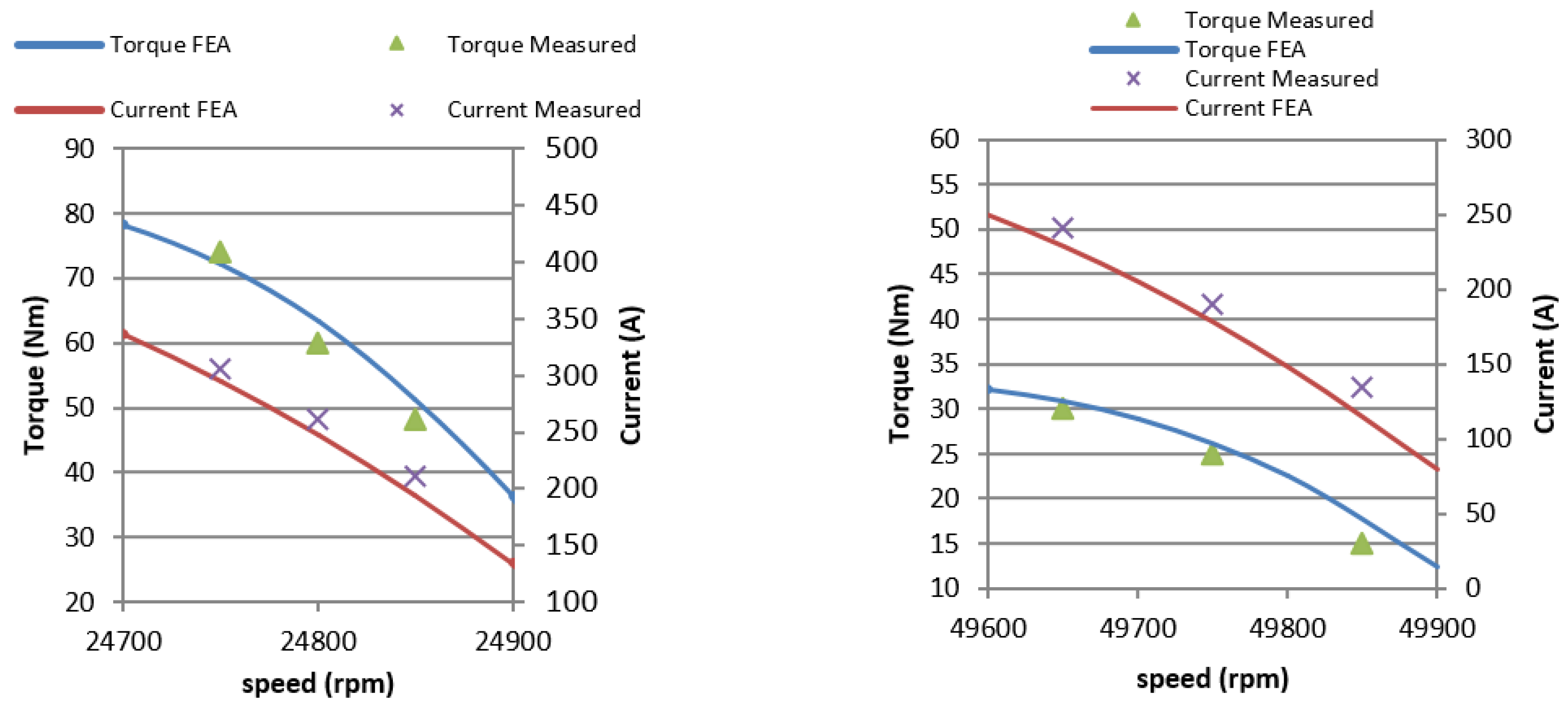
As an example,
Figure 6 shows the torque versus slip characteristic of three IMs with different power ratings sharing the same lamination geometry. The different power ratings are achieved lengthening the stack and changing the number of conductors. Besides the torque characteristic, other relevant quantities, such as losses, power, efficiency and so on, can be computed with good agreement with experimental results. This simulation strategy has been profitable adopted to analyse and compute the performance of several three-phase and single phase IMs of various power ratings.
The coupled thermal model is based on lumped parameters thermal network [
23]. An example is shown in
Figure 7 for an IM with a water jacket. A thermal model of the machine is particularly important when specific cooling system is adopted. This is the case, for example, of high power density machines. The thermal model is coupled with the electromagnetic one to update the parameters and to increase the accuracy of performance prediction. Thermal capacitance can also be included in the thermal model when dynamic behaviour has to be investigated. Both electric and thermal circuits are solved jointly in order to update each other iteratively [
24].
Some other simulation techniques can be adopted in order to further improve the computation accuracy. For example it is possible to include eddy current losses in the lamination using homogenization techniques. Such additional effort requires an additional computational time but could be of interest in applications where iron losses become important. An example of such computational techniques applied to IM are reported in References [
25,
26].
2.4. Power Electronics
The main objective of the power electronics for a high-speed drive is to synthesize a low-distortion sinusoidal current waveform with high fundamental frequency. Considering that:
the ratio between the switching and sampling frequency and the fundamental frequency constitutes one of the main control parameters for the drive,
the switching frequency of the silicon power devices is limited, a high-speed drive is operating with a switching/fundamental ratio quite low. For the majority of the applications that rely on standard time-continuous control design, recommended values for this ratio is 15–20. This leads to switching frequencies in the order of 50 kHz for high-speed applications in the range of tens of kW.
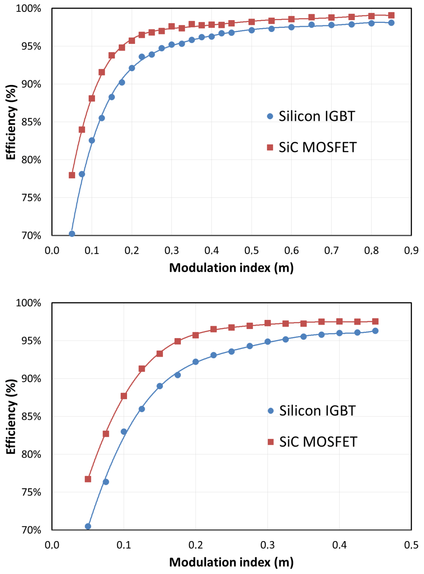
In this framework, wide-bandgap devices have received increasing attention from both industry and academia because of their attractive characteristics in terms of low conduction and switching losses, higher thermal conductivity (for SiC), higher switching frequency capability and possible operation at higher temperatures. One of the first attempts towards the evaluation of wide-bandgap devices for electric drives was to substitute the silicon devices in the actual designs and evaluate the performance. Marked increase in the efficiency was demonstrated by several researchers [
27],
Figure 8. SiC MOSFETs showed also a better stability of their characteristics with increased temperature. Higher efficiency with the same operational parameters can be exploited either by reducing the cooling requirements or by increasing the switching frequency to decrease the size and cost of the magnetic components. In particular, if the same point of operation were chosen for both Si and SiC, the higher efficiency of the latter would lead to a reduced thermal stress and possibly longer lifetime.
It has been shown that with the advancement of the technology and of the increased market penetration of variable frequency drives, the concerns in terms of reliability are growing and special design procedures as the design for reliability based on the physics of failure approach are attracting the interest. In this framework, it has been already demonstrated that SiC devices can offer efficient and high switching frequency operation for the high-speed drives, however, how these characteristics can be fully exploited depends on the machine itself. Among the possible failures of the electrical machines are the bearing faults and the stator insulation fault. The bearing faults can be accelerated by the high-frequency currents due to the common-mode PWM harmonics because of the capacitive coupling between the windings and the ground. Lower machine inductance and higher switching frequency, that represents the key aspects of high-speed drives, increase the magnitude of this current. A possibility to reduce the leakage current with a conventional power electronics topology is to employ an optimized modulation strategy [
28]. In fact, considering a three-phase converter, there are 8 possible switching states: six active vectors (
) and two zero vectors (
). Each vector implies a different value of common mode voltage and the commutation between one vector to the other causes high-frequency common mode voltage variation that originates the leakage current. A possibility to mitigate the phenomenon is to choose between vectors with the same common mode voltage. This normally leads to the avoidance of the zero vectors and to high switching harmonics in the motor current.
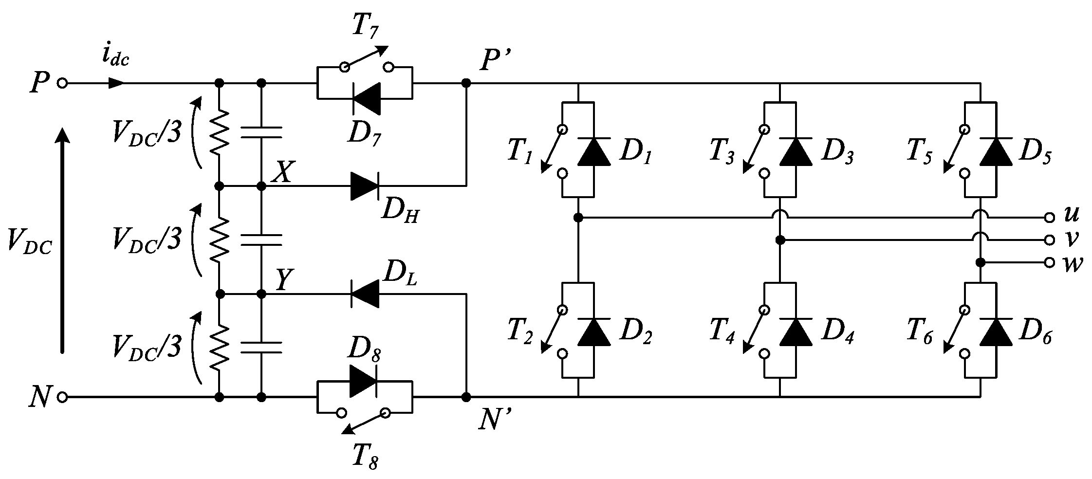
Some topologies [
29,
30] tried to address the common-mode voltage generation with SiC power converter by modifying the three-phase bridge. This is shown in
Figure 9, where additional devices are placed in the DC rails to decouple the DC and AC side of the converter during the free-wheeling phases. Proper space vector modulation ensures a reduction of the common-mode voltage. The peculiarity of this converter is that it allows to use the zero vectors with the same common mode voltage of the active vectors, as highlighted in
Table 2, where the normalized output voltage (
) together with the normalized common mode voltage
of the conventional three-phase converter (H6) and the H8 converter is listed.
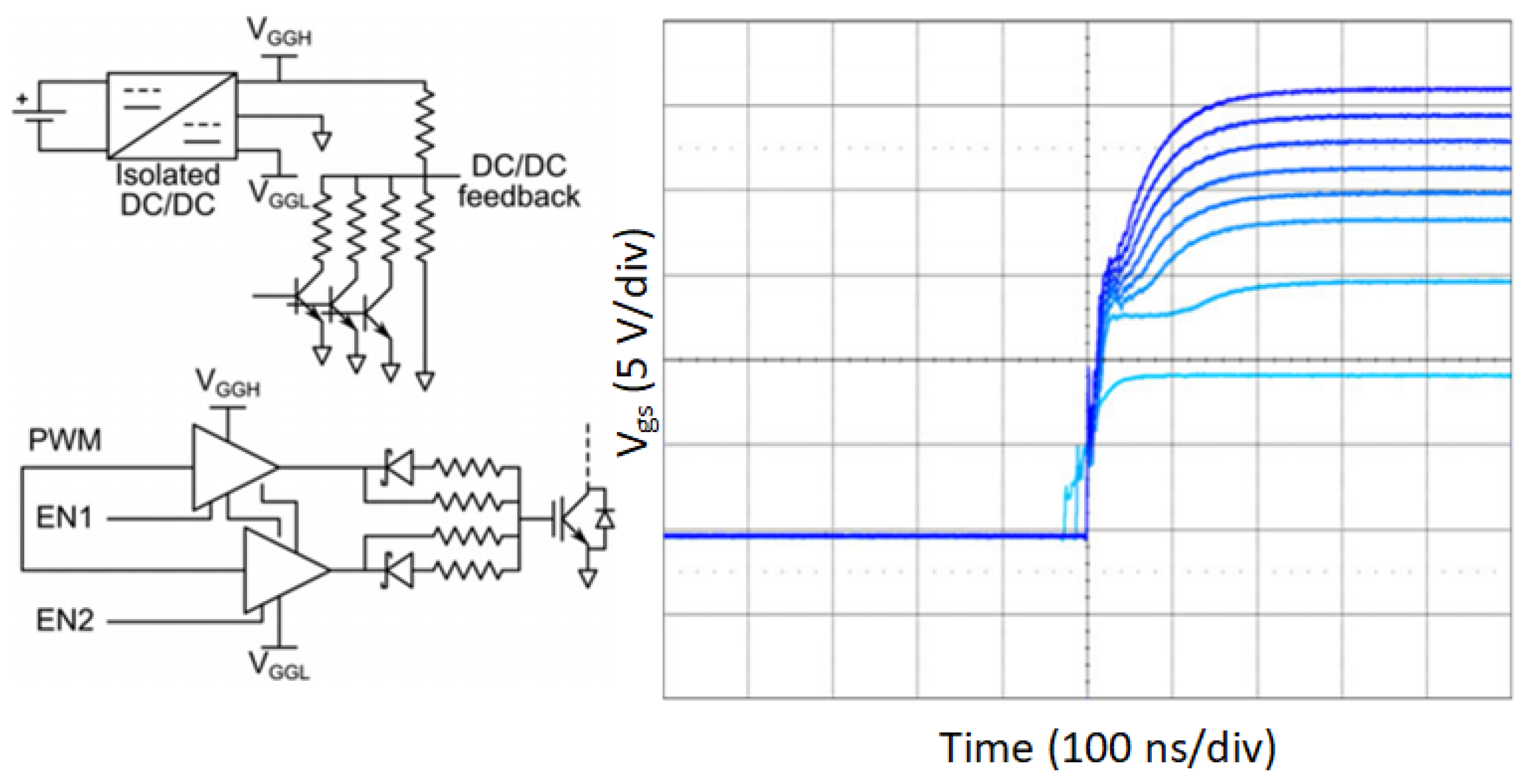
As discussed, the voltage stress causes the inter-turn insulation failure. Both the dv/dt and the switching frequency contribute to this effect and WBG-based drives for high-speed machines fall into this worst case for the machine. The basic problem is that the full characteristics of the WBG devices cannot be exploited if this leads to an over-designed machine in terms of insulation thickness to meet the reliability requirements. Technological solutions to adapt the voltage stress depending on the design targets require the use of active gate drivers, as the one proposed in Reference [
31], where the voltage and the current of the gate can be modified to control the dv/dt of a SiC MOSFET power module. An effective possibility to realize this voltage derivative control is shown in
Figure 10, where an array of gate driver resistors is adopted, allowing to select among different transients. This would give the designers an additional degree of freedom to perform global converter/machine optimization. The reduced voltage stress of multi-level inverters could be exploited in this application to reduce the voltage stress of the electrical machines and, at the same time, improve the power quality and reduce the machine losses [
32].
4. Conclusions
The induction machine has had a safe place in the global market because of its ease of use, reliable construction and low cost. The global changes in terms of industry modernization and the tight international regulation regarding the efficiency are pushing the designers towards new approaches.
In this manuscript, it has been shown how the induction machine, despite having lower rated efficiency than the permanent magnet or the synchronous machines, can still constitute the optimal solution for some high speed applications. Needless to be say, this kind of induction machine is not the low-cost/low-efficiency and easy to use kind that contributed to the success of this type of machine but it is a new design with high-performance materials and advanced power electronics. Although the traditional low cost machine is slowly being abandoned, these advanced design are just starting to make their appearance.
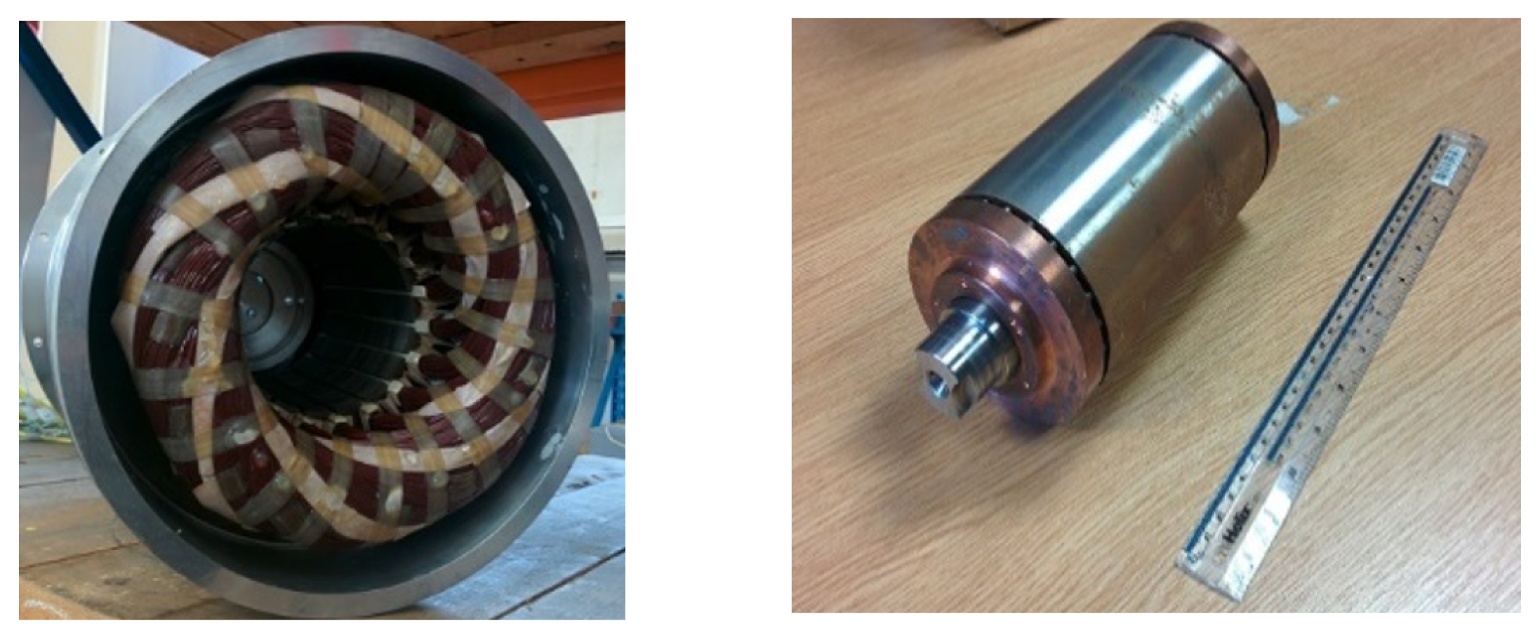
A case study for a high-performance naval application has been analyzed to support these statements and it has demonstrated that a solution based on an induction machine can outperform a solution based on permanent magnet machine. Although this result cannot have a general validity in the global context, it demonstrates that a holistic design that considers all the aspects of an electric drive must be performed to reach an optimized solution. To this aim, a comprehensive set of tools, including numerical simulation, finite element analysis, special power electronics must be considered.

 ,
, 


