A New Wind Power Accommodation Strategy for Combined Heat and Power System Based on Bi-Directional Conversion


Department of Electric Engineering, Northeastern University, Shenyang 110004, China
*
Author to whom correspondence should be addressed.
Energies 2019, 12(13), 2458; https://doi.org/10.3390/en12132458
Submission received: 31 May 2019
/
Revised: 24 June 2019
/
Accepted: 25 June 2019
/
Published: 26 June 2019
Abstract
:The extensive use of wind power can not only reduce dependence on fossil fuels, but also reduce emissions of polluted gases. However, large-scale wind power curtailments often occur in northeast China during the heat supply season, due to the fact that most of electrical demand is covered by the electrical power of the combined heat and power (CHP) during the off-peak hours. At present, for northeast China with heating demand, most of the research only focuses on how to accommodate more wind power on the spot by using one-directional conversion of the electric and thermal energy. But it is still difficult to realize the bi-directional conversion between the electro-gas or electro-thermal energy. In this paper, a combined electro-gas bi-directional conversion system (CEGBCS) is established by adding the power to gas (P2G), fuel cell and heat storage device in CHP system. This CEGBCS can not only realize bi-directional conversion of the electricity and gas, but also decouple the two operation modes of CHP unit, which greatly improve the ability of system to accommodate additional wind power. Finally, the effectiveness of the proposed CEGBCS is verified by comparing with two traditional methods.
1. Introduction
Due to the uncertainty and volatility of wind power, it is impossible to be directly connected to the grid in a large scale at present [1,2]. The phenomenon of wind power curtailments often occurs in China, especially in the northeast China, where the accommodation of wind power is limited since the electric power of the combined heat and power (CHP) is enough for the electric load demand during most off-peak hour [3]. According to the national wind power statistics, the amount of wind power curtailments in China in the first half of 2017 is as high as 2.35 × 10¹¹ kW·h, causing direct economic losses more than 1.8 × 10¹⁰ yuan [4].
At present, there are mainly three methods to increase the wind power accommodation [5,6]: (1) Direct storage of wind power using batteries [7,8,9,10]; (2) Expanding the capacity of the power grid; (3) Converting remaining wind power of system into other types of energy, such as pumped storage method [11,12], heat storage method, and gas storage method. In Reference [13], the cooperative operation of electric boiler and thermal power plant is used to improve the system’s ability to accommodate wind power. A scheduling model based on CHP, heat storage device, and demand response is proposed in Reference [14]. To further increase the ability to accommodate wind power, the coordinating operation method is proposed among the heat storage device, CHP unit, heat storage device, or pumping energy storage in References [15,16]. The research in Reference [17] shows that by adding electric boiler and heat storage device into the CHP system, the operation of the CHP system is more flexible. In Reference [18], by adding electric boilers and heat pumps to the central heating system, the ability to accommodate wind power is improved.
In brief, above mentioned methods mainly improve the wind power accommodation in two ways: (1) Accommodating excess wind power in the system by converting the electric energy into storable thermal energy. (2) Decoupling the “Following the thermal load” mode of CHP units to improve the ability to accommodate wind power. However, these methods make it difficult to realize bi-directional conversion between the electro-gas or electro-thermal energy. Furthermore, even if the excess wind power is converted into thermal energy, it is difficult to store the thermal energy for a long time. Therefore, it is necessary to find another way or device to store the excess energy.
On the other hand, the emissions of polluted gases and energy purchase cost also play an important role for the operation of CHP systems. Therefore, in this paper, we establish a combined electro-gas bidirectional conversion system (CEGBCS) containing P2G, fuel cell, heat storage device, and CHP. This CEGBCS can not only promote the wind power accommodation, but also reduce the emissions of polluted gases and energy purchase cost. Totally, the contributions of this paper are as follows:
- Decouple two operating modes of CHP units simultaneously, i.e., “Following the Electric Load” and “Following the Thermal Load”, which further improve the ability to accommodate wind power.
- Realize electro-gas bidirectional conversion (wind power to gas to electricity) by P2G and fuel cell, which can realize indirect power supply of wind power across time scales.
- Store the large-scale excess wind power, i.e., the wind power which cannot be used by electric load, in the form of gas by using P2G technology. When the user needs electrical energy or thermal energy, the gas produced by P2G is used to generate power.
The paper is structured as follows: In Section 2, the operating characteristics of power to gas (P2G) and proton exchange membrane fuel cell (PEMFC) in CEGBCS are introduced. The dual-mode decoupling of CEGBCS and its wind power accommodation strategy are described in detail in Section 3. The coordinated optimal scheduling of CEGBS is provided in Section 4, and the case study is presented in Section 5. Finally, the conclusions are drawn in Section 6.
2. Operation Characteristics of Internal Devices in Combined Electro-Gas Bi-Directional Conversion System (CEGBCS)
The following part mainly introduces the operating characteristics of the power to gas and proton exchange membrane fuel cell in CEGBCS.
2.1. Operating Characteristics of Power to Gas
According to the type of gas that is eventually produced, power to gas (P2G) can be divided into two main categories [19,20]: electric methane production (electric natural gas production) and electric hydrogen production. Both the technologies have their own advantages and disadvantages, and detail information can be found in Reference [21]. In this paper, the P2G used in CEGBCS is electric methane production, whose core principle is composed of two parts [22,23]. Firstly, hydrogen and oxygen are produced by electrolytic water. Then, under the action of catalyst, the hydrogen obtained by electrolytic water and CO2 pass through “Sabatier Reaction” to obtain CH4 and H2O. Here, “Sabatier Reaction” is used to denote the chemical reaction in which CO2 is hydrogenated. This reaction can occur chemically with a catalyst or biochemically with archaea. In this paper, the term of “Sabatier Reaction” refers to chemical reaction.
The methane produced by this reaction is called “Renewable Power Methane (RPM)” [24]. The working principle is shown in Figure 1.
P2G technology can transform the excess electricity of system into methane and store it in the natural gas pipeline network. When the system needs electricity, it supplies gas turbines and fuel cells for power generation. P2G not only provides a new way for indirect storage of electric energy, but also increases the system’s ability of wind power accommodation. At present, the conversion efficiency of P2G technology can reach 60−70% [25].
2.2. Operating Characteristics of Proton Exchange Membrane Fuel Cells
Fuel cell is a device that produces electric energy by chemical reaction under hydrogen containing fuel and oxidant [26]. The fuel cell used in this paper is a Proton Exchange Membrane Fuel Cells (PEMFC) [27,28]. It uses natural gas as fuel, and its chemical reaction equation is as shown in formula (1).
Fuel cell is a controllable power generation equipment. It can be used to regulate the power and enhance the response speed of the system. At present, the conversion efficiency of PEMFC is over 60% [29].
3. Dual-Mode Decoupling of Combined Electro-Gas Bi-Directional Conversion System (CEGBCS) and Wind Power Accommodation Strategy
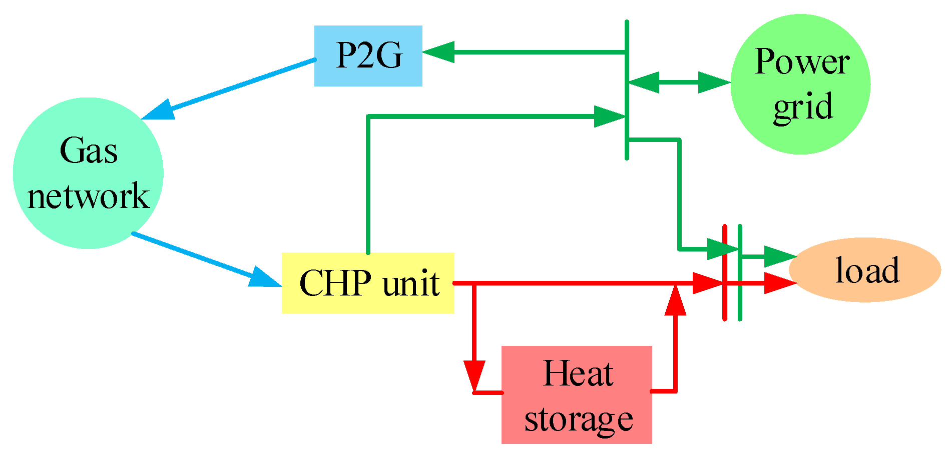
The CEGBCS proposed in this paper is as shown in Figure 2. It consists of P2G, fuel cell, heat storage device, and CHP unit. The reason for decoupling the relationship of the electric power and thermal power of CHP units is to further improve the system’s ability to accommodate wind power. The following part will introduce how to decouple two modes of CHP unit by CEGBCS and further present the wind power accommodation strategy.
3.1. Decoupling Principle of Combined Heat and Power (CHP) for the Mode of “Following the Thermal Load”
The mode of “Following the Thermal Load” (FTL) of CHP means that the operating status of CHP is determined by thermal load. In other words, CHP preferentially meets thermal load demand, and the system unconditionally accepts the produced electric energy.
In this paper, the principle for decoupling the FTL mode by CEGBS is shown in Figure 3.
In order to meet the users’ thermal demand firstly, CHP unit operates in the mode of “Following the Thermal load”. The excess electric power generated by CHP unit, i.e., the power which cannot be consumed by user or connected to gird, could be consumed by P2G. Therefore, the excess power will not affect the electrical load side. When the demand for heat load is low and the demand for electricity load is high, the CHP unit generates as much electric energy as possible within its economic scope, and the excess heat energy generated by CHP is stored in the heat storage device. Thus, the excess thermal energy will not affect the thermal load, either.
3.2. Decoupling Principle of Combined Heat and Power (CHP) for the Mode of “Following the Electric Load”
The mode of “Following the Electric Load” (FEL) of CHP means that the operating status of CHP is determined by electric load. In other words, CHP preferentially meets electric load demand, and the system unconditionally accepts the produced thermal energy.
In this paper, the principle for decoupling the FEL mode of CHP is shown in Figure 4.
In order to meet the users’ electric demand firstly, CHP unit operates in the mode of “Following the Electric Load”. When the heat storage device reaches full storage, the excessive electric demand in the system can be satisfied by increasing the fuel cell output, thereby avoiding the impact of excessive thermal energy on user’s comfort. Furthermore, the capacity of the heat storage device can be reduced, which can decrease the cost in some extent.
3.3. Wind Power Accommodation Strategy
When the intermittent renewable energy is accommodated or dispatched, the corresponding control strategies need to be proposed [30,31]. The CEGBCS proposed in this paper is to improve the ability of the system to accommodate wind power from two aspects. Firstly, based on the structure of system, the ability of the system to accommodate wind power is improved by decoupling the relationship of the electric power and thermal power of CHP units, which can increase the flexibility of system. Secondly, from the aspect of optimal scheduling, by minimizing the objective function composed of the energy purchase cost and pollution gas treatment cost, the electric load in the system will preferentially accommodate wind power of system. Then, the remaining wind power is transformed into storable natural gas by using P2G technology. Figure 5 shows how CEGBCS accommodates wind power by optimal scheduling method.
4. Coordinated Optimal Scheduling of Combined Electro-Gas Bi-Directional Conversion System (CEGBS)
4.1. Mathematical Modeling of Combined Electro-Gas Bi-Directional Conversion System (CEGBS) Internal Devices
4.1.1. Combined Heat and Power (CHP) Unit Model
In this paper, the CHP unit is composed of a gas turbine and waste heat recovery device. The relationship between the output electric power and thermal power of the gas turbine is as follows:
where, and represent the output electric power and thermal power of gas turbine respectively (kW); and are the power generation efficiency and energy loss of gas turbine respectively; , and are the amount of natural gas consumed by the gas turbine (m3), the low calorific value of natural gas (kWh/m3), and the thermoelectric ratio of the gas turbine respectively.
The heat energy recovered by waste heat recovery device is as follows:
where, is the thermal power output of the waste heat recovery device (kW); is the conversion efficiency of waste heat recovery device.
4.1.2. Power to Gas (P2G)
The relationship between the produced natural gas and the consumed electric power for P2G is as follows:
where, is the gas produced by the P2G (m3); is the conversion efficiency of P2G; is electric energy consumed by P2G (kW).
4.1.3. Fuel Cell Model
The fuel cell in this paper uses natural gas as fuel to generate electricity. The relationship between the produced electricity and the consumed natural gas is as follows:
where, is the gas consumed by the fuel cell (m3); is the efficiency of fuel cell; (kW) is electric energy produced by fuel cell.
4.1.4. Heat Storage Model
Heat storage device stores thermal energy at time is related to the thermal energy at time and the thermal energy charge or release at time . The formula of heat storage device is as follows:
where, represents the storage of thermal energy of heat storage device at t + 1 (kWh). (kWh) represents the storage of thermal energy of heat storage device at t. is the heat loss rate of heat storage devices; and are the charging and discharging efficiency of heat storage device, respectively; and are the heat charge power and heat discharge power of the heat storage device, respectively.
4.2. Coordinated Optimization Modeling of Combined Electro-Gas Bi-Directional Conversion System (CEGBS)
4.2.1. Objective Function of Optimal Scheduling
In this paper, the objective is to minimize the energy purchase cost and environmental cost. The specific objective function is as follows:
where, is the total operating cost of system (yuan); is the system’s energy purchase cost (yuan); is environmental costs (yuan).
1. System Energy Purchase Cost
The formula for calculating the cost of electricity purchase is as follows:
where, is the price of electricity purchased (or sold) at different times of a day (yuan/kWh); is the electric power purchased from grid at time (kW).
The formula of gas purchase cost is as follows:
Substituting Equation (2), Equation (5), and Equation (6) into Equation (11), the gas purchase cost can be further obtained by:
where, is the price of natural gas (2.5714 yuan/m3). , and are the natural gas consumed by gas turbines, the natural gas consumed by fuel cells, and the natural gas produced by P2G, respectively(m3). , and are the electric power output by the gas turbine, the electric power output by the fuel cell, and the wind power used by P2G at time , respectively (kW); , and are conversion efficiency of gas turbine, fuel cell, and P2G, respectively.
According to Equation (11) and Equation (12), the cost of purchasing energy of the system is as follows:
2. Environmental Cost
The environmental cost is mainly the equivalent CO2 processing cost. It is mainly composed of three parts: equivalent CO2 emission from electricity purchase in distribution network, equivalent CO2 emission from gas purchase in gas network, and the equivalent CO2 absorption by P2G [23]. The formula is as follows:
where, is the unit processing cost of CO2, (yuan/kg); and represent equivalent CO2 emission factors for electricity purchases and gas purchases (kg/kWh).
4.2.2. Operational Constraints
1. Equality Constrains
where, is accommodated wind power by system’s electric load through the optimal dispatching at time t (kW); is the accommodated wind power by P2G at time t (kW); is the total wind power consumption at time t (kW); , , and are the output power of the gas turbine, fuel cell, and P2G, respectively (kW); is the electric load of system (kW). , , , and represent the thermal energy produced by the waste heat boiler, the thermal energy produced by the heat storage device, the thermal energy stored in the heat storage device, and the thermal energy required by user (kW); is the variable which only equals 0 or 1.
2. Inequality Constrains
where, and are the maximum constraints on feeding and purchasing power (kW); is the maximum heat storage power(kW); is the maximum heat release power(kW); and represent the minimum and maximum heat storage, respectively(kWh).
4.2.3. Solution Method
At present, there are many methods to solve optimization problems, such as evolutionary algorithm [32] or numerical algorithm [33]. In this paper, we use Yalmip, which is a toolbox of MATLABR2014a to solve the optimization problem. Yalmip is a simple, practical, and efficient mathematical modeling tool, which can be invoked by MATLAB. After modeling the optimization problem with Yalmip, it will invoke the appropriate solver (such as, gurobi, cplex, fmincon, etc.) in MATLAB to solve the optimization problem. Fmincon is a solver in MATLAB, which is used in this paper to find the optimal solution.
In order to use Yalmip in Matlab, we first write the standard form of the model as follows [34]:
where, is the objective function of optimal scheduling, which is represented by Equation (9). is the decision variable of optimization problem, which contains wind power accommodation, the active power output of the devices in the system, the charging and discharging of the heat storage device, and the purchase of electricity from the power grid. Equations (15) to (18) consist of the equality constraints. Inequality constraints are composed by Equations (19) to (26).
5. Simulation Study
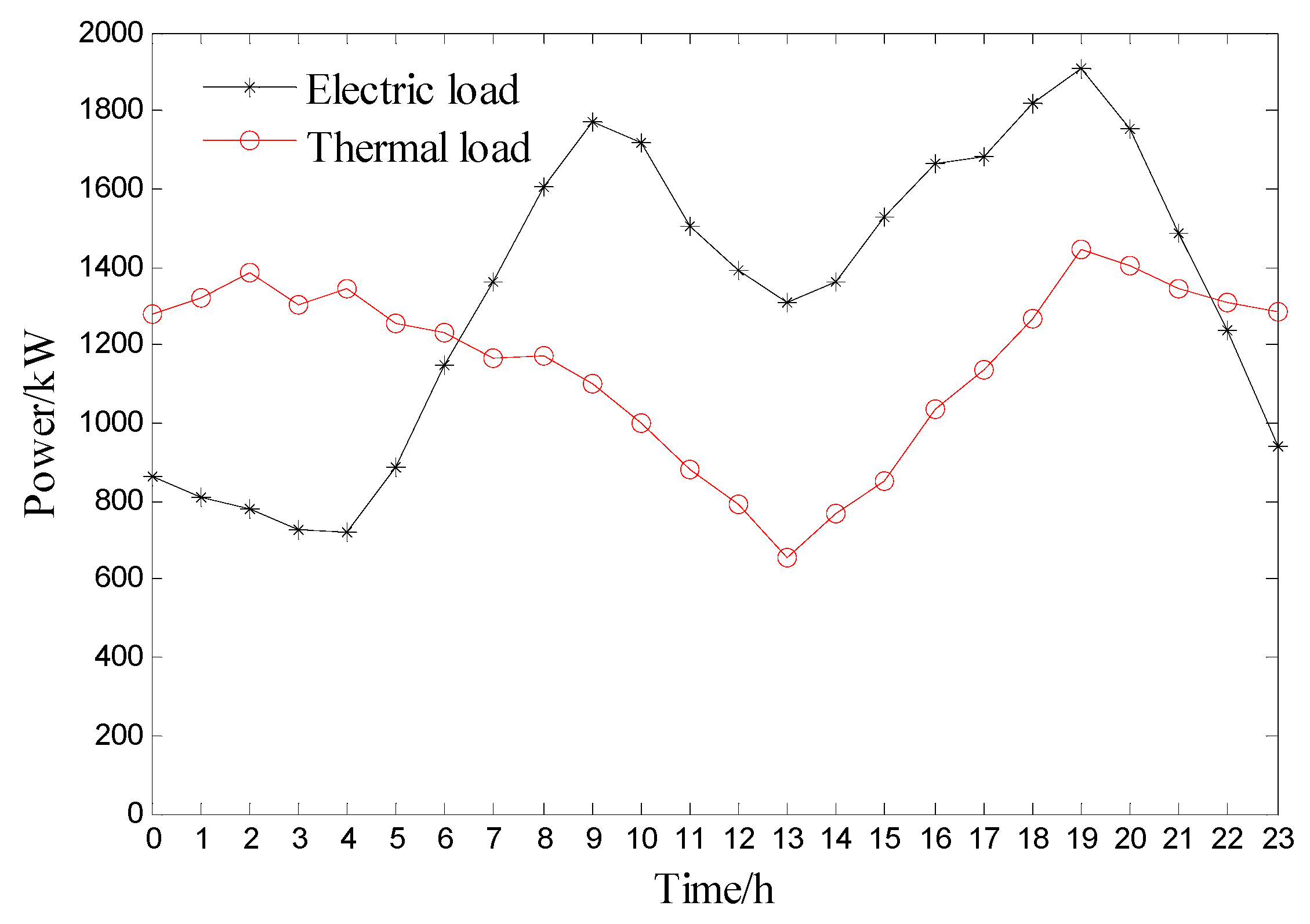
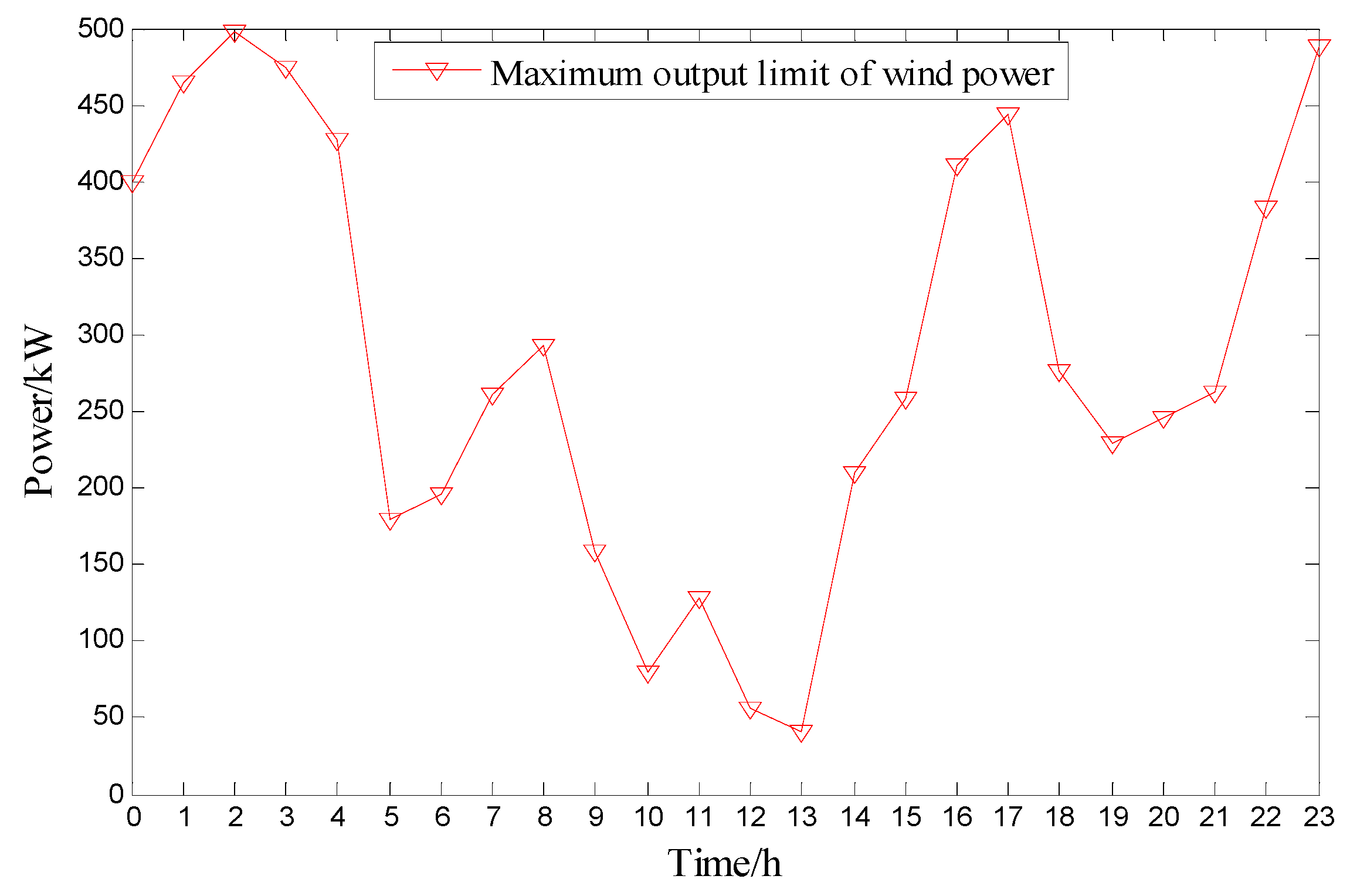
In this section, the effectiveness of CEGBCS proposed in this paper is verified. Firstly, the simulation parameters, the time-sharing electricity price of a day, the typical daily thermoelectric load curve, and the maximum output prediction curve of wind power generation without restriction are given in Table 1 and Figure 6, Figure 7 and Figure 8, respectively. Then, two traditional wind power accommodation methods are introduced in Scenarios 1–2, which are used to compare with the approach proposed in this paper. Finally, the effectiveness of the proposed method in accommodating wind power is verified by the simulation analysis.
5.1. Scenario Description
In order to verify the effect of wind power accommodation, the CEGBCS proposed in this paper is compared with two traditional models [15,17].
Scenario 1: Only the thermal storage device is used in the CHP system (traditional model). Its structure diagram is shown in Figure 9;
Scenario 2: Both the electric boiler and thermal storage device are used in CHP system (traditional model). Its structure diagram is shown in Figure 10;
Scenario 3: The P2G, thermal storage device and fuel cell are used in CHP system (i.e., CEGBCS proposed in this paper). Its structure diagram is shown in Figure 2.
The detailed composition of each scenario is as shown in Table 2, where the symbol “√” means that the device is included in scenario, and the symbol “×” indicates that the device is not included in the scenario. GT is gas turbine; HB is waste heat recovery device; FC is fuel cell; P2G is power to gas; EB is electric boiler; WT is wind turbine; HS is heat storage device. Maximum electric power of EB is 700 kW, and efficiency of EB is 0.98.
5.2. Simulation Result Analysis
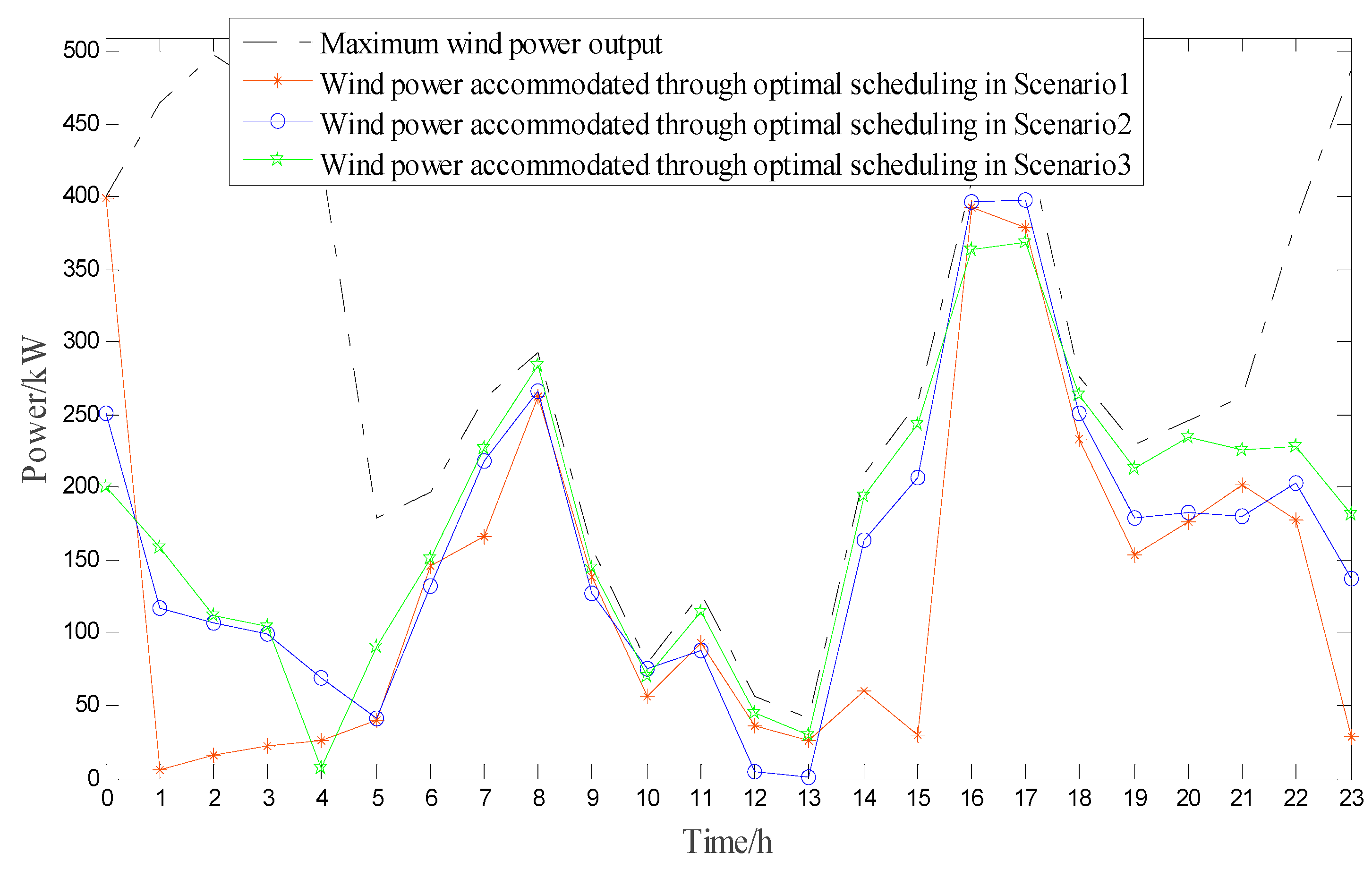
Table 3 and Figure 11 shows the comparison of wind power accommodation by the same electric load. As shown in Table 3, the total wind power accommodation by electric load in Scenario 1 is 3640.85 kW, the total wind power accommodation by electric load in Scenario 2 is 4011.97 kW, and the total wind power accommodation by electric load in Scenario 3 is 4278.58 kW. This shows that the wind power accommodation by electric load in Scenario 3 is higher than other Scenarios. Meanwhile, the wind power accommodation by electric load in Scenario 3 is increased by 17.52% than Scenario 1, the wind power accommodation by electric load in Scenario 3 is increased by 6.65% than Scenario 2.
The optimal costs of different Scenarios are shown in Table 4. As shown in Table 4, although the cost of gas purchase in Scenario 3 is higher than Scenario 1 and Scenario 2, the cost of electricity purchase, environmental cost and total operation cost in Scenario 3 is less than other two scenarios. The total cost of scenario 3 is less due to two factors: (1) The wind power accommodation by electric load in scenario 3 is more than other two scenarios, and this leads to a reduction in electricity purchases from the grid. (2) When P2G accommodate excess wind power, a large amount of CO2 in the air is absorbed by P2G, thus the environment treatment cost is reduced.
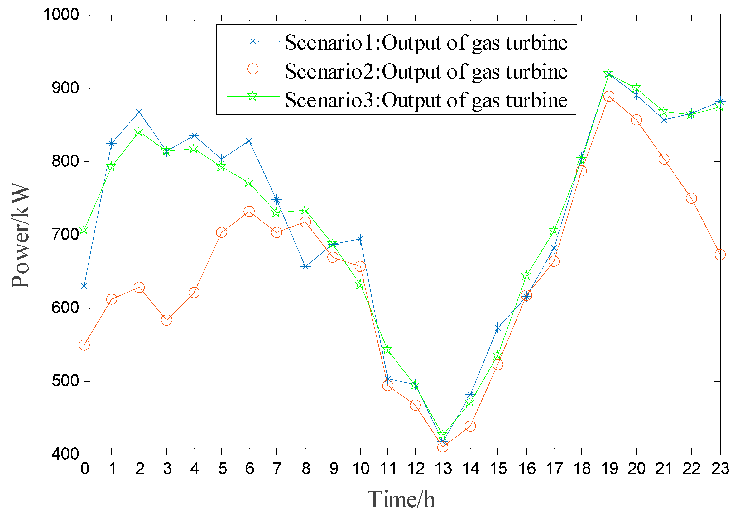
Figure 12 shows a comparison of the energy change of heat storage device in different scenarios. As shown in Figure 12, energy change of heat storage device in Scenario 1 and Scenario 2 appear large fluctuations during the time interval from 7 a.m. to 16 p.m. Energy change of heat storage device in Scenario 3 is relatively flat. Figure 13 shows a comparison of produced thermal energy by gas turbine in different scenarios. It can be seen from the figure that the produced thermal energy by gas turbine in scenario 2 is less than scenario 1 and scenario 3. This is because there are three heat sources (electric boiler, heat storage device, and CHP unit) in scenario 2, while in the other scenarios there are only two heat sources (heat storage device and CHP unit) to provide thermal energy for users. Therefore, the gas turbine of scenario 2 has less thermal energy output.
Figure 14 shows the total wind power accommodation of scenario 3 (i.e., CEGBCS proposed in this paper). It can be seen from the figure that the wind power in the system is divided into two parts for accommodation. First, through coordinated optimal operation, the electric load in the system can accommodate wind power as much as possible. Then the remaining wind power, which cannot be accommodated by electric load, is used by P2G to produce natural gas.
Figure 15 and Figure 16 are optimal scheduling of the heat power and electric power in scenario 3, respectively. In this dispatch model, due to ignoring the thermal inertia, the electric power value and heat power value of each unit are equal to the electric load demand and the thermal load demand. It can be discovered from Figure 15 that during the time interval from 6 a.m. to 22 p.m., the fuel cell produces electric power to decrease the purchased electricity amount from the grid. By Figure 16, it can be discovered that most of the thermal demand in the system are met by CHP.
6. Conclusions
In this paper, a combined electro-gas bidirectional conversion system (CEGBCS) with P2G, fuel cell, and heat storage device is proposed. The main contribution of CEGBS is that it can effectively solve the problem of wind curtailments in northeast China during the heat supply season. Compared with the traditional method, the proposed method has the following characteristics:
- This system can simultaneously decouple two operating modes (“Following the Electric load” and Following the Heat load) of CHP unit.
- The CEGBS system can also realize large-scale local accommodation of wind power and long-term, low-cost indirect storage of remaining wind power.
- The CEGBCS can realize bidirectional conversion between the electro-gas or electro-thermal energy.
- The simulation results show that the CEGBCS proposed in this paper is not only superior to the existing methods, but also has the lowest operating cost and the best environmental benefit.
Author Contributions
All of the authors have contributed to this research. The original ideas were provided by Y.L. The revision of the draft was guided by Z.Y. Some theoretical analysis was given by D.Y. and B.Z.
Funding
This work was supported by the National Natural Science Foundation of China (61703081), Natural Science Foundation of Liaoning Province (20170520113) and the State Key Laboratory of Alternate Electrical Power System with Renewable Energy Sources (LAPS19005).
Conflicts of Interest
The authors declare no conflict of interest.
References
- Xue, Y.; Lei, X.; Xue, F.; Yu, C.; Dong, Z.; Wen, F.; Ju, P. A review on impacts of wind power uncertainties on power systems. Proc. CSEE 2014, 34, 5029–5040. [Google Scholar]
- Holttinen, H.; Meibom, P.; Orths, A.; Lange, B.; O’Malley, M.; Tande, J.O.; Estanqueiro, A.; Gomez, E.; Söder, L.; Strbac, G. Impact of large amounts of wind power on design and operation of power systems, results of IEA collaboration. Wind Energy 2011, 14, 179–192. [Google Scholar] [CrossRef]
- Liu, D.; Zhang, G.; Huang, B.; Liu, W. Optimum electric boiler capacity configuration in a regional power grid for a wind power accommodation scenario. Energies 2016, 9, 144. [Google Scholar] [CrossRef]
- State Energy Administration Wind Power Grid Operation in the First Half of 2017. Available online: http://www.nea.gov.cn/2017-07/24/c_136468307.htm (accessed on 24 July 2017).
- Zhang, L.; Ye, T.; Xin, Y.; Han, F.; Fan, G. Problems and measures of power grid accommodating large scale wind power. Proc. CSEE 2010, 30, 1–9. [Google Scholar]
- Luo, X.; Wang, J.; Dooner, M.; Clarke, J. Overview of current development in electrical energy storage technologies and the application potential in power system operation. Appl. Energy 2015, 137, 511–536. [Google Scholar] [CrossRef] [Green Version]
- Brekken, T.; Yokochi, A.; von Jouanne, A.; Yen, Z.Z.; Hapke, H.M.; Halamay, D.A. Optimal energy storage sizing and control for wind power applications. IEEE Trans. Sustain. Energy 2011, 2, 69–77. [Google Scholar] [CrossRef]
- Atwa, Y.; El-Saadany, E.F. Optimal allocation of ESS in distribution systems with a high penetration of wind energy. IEEE Trans. Power Syst. 2010, 25, 1815–1822. [Google Scholar] [CrossRef]
- Zhen, L.; Hu, W.; Lu, Q.Y.; Min, Y.; Yuan, F.; Gao, Z. Research on planning and operation model for energy storage system to optimize wind power integration. Proc. CSEE 2014, 34, 2533–2543. [Google Scholar]
- Zheng, Y.; Dong, Z.; Luo, F.; Meng, K.; Qiu, J.; Wong, K.P. Optimal allocation of energy storage system for risk mitigation of DISCOs with high renewable penetrations. IEEE Trans. Power Syst. 2014, 29, 212–220. [Google Scholar] [CrossRef]
- Hu, Z.; Ding, H.; Kong, T. A joint daily operational optimization model for wind power and pumped-storage plant. Autom. Electr. Power Syst. 2012, 36, 36–41. [Google Scholar]
- Zhang, N.; Kang, C.; Kirschen, D.S.; Xia, Q.; Xi, W.; Huang, J.; Zhang, Q. Planning pumped storage capacity for wind power integration. IEEE Trans. Sustain. Energy 2013, 4, 393–401. [Google Scholar] [CrossRef]
- Lyu, Q.; Jiang, H.; Chen, T.; Wang, H.; Lyu, Y.; Li, W. Wind power accommodation by combined heat and power plant with electric boiler and its national economic evaluation. Autom. Electr. Power Syst. 2014, 38, 6–12. [Google Scholar]
- Li, W.; Li, T.; Wang, H.; Dong, J.; Li, Y.; Cui, D.; Ge, W.; Yang, J.; Okoye, M.O. Optimal dispatch model considering environmental cost based on combined heat and power with heat energy storage and demand response. Energies 2019, 12, 817. [Google Scholar] [CrossRef]
- Chen, L.; Xu, F.; Wang, X.; Min, Y.; Ding, M.; Huang, P. Implementation and effect of heat storage in improving wind power accommodation. Proc. CSEE 2015, 35, 4283–4290. [Google Scholar]
- Zhang, N.; Lu, X.; McElroy, M.; Nielsen, C.P.; Chen, X.; Deng, Y.; Kang, C. Reducing curtailment of wind electricity in China by employing electric boilers for heat and pumped hydro for energy storage. Appl. Energy 2016, 184, 987–994. [Google Scholar] [CrossRef] [Green Version]
- Chen, X.; Kang, C.; O’Malley, M.; Xia, Q.; Bai, J.; Chun, L.; Sun, R.; Wang, W.; Li, H. Increasing the flexibility of combined heat and power for wind power integration in China: Modeling and implications. IEEE Trans. Power Syst. 2015, 30, 1848–1857. [Google Scholar] [CrossRef]
- Meibom, P.; Kiviluoma, J.; Barth, R.; Brand, H.; Weber, C.; Larsen, H.V. Value of electric heat boilers and heat pumps for wind power integration. Wind Energy 2010, 10, 321–337. [Google Scholar] [CrossRef]
- Qadrdan, M.; Abeysekera, M.; Chaudry, M.; Wu, J.; Jenkins, N. Role of power-to-gas in an integrated gas and electricity system in Great Britain. Int. J. Hydrog. Energy 2015, 40, 5763–5775. [Google Scholar] [CrossRef]
- Chen, Z.; Wang, D.; Jia, H.; Wang, W.; Guo, B.; Qu, B.; Fan, M. Research on optimal day-ahead economic dispatching strategy for microgrid considering P2G and multi-source energy storage system. Proc. CSEE 2017, 37, 3067–3077. [Google Scholar]
- Yan, X.; Zhang, X.; Gu, C.; Li, F. Power to gas: Addressing renewable curtailment by converting to hydrogen. Front. Energy 2018, 12, 1–9. [Google Scholar] [CrossRef]
- Tsupari, E.; Janne, K.; Vakkilainen, E. Economic feasibility of power-to-gas integrated with biomass fired CHP plant. J. Energy Storage 2016, 5, 62–69. [Google Scholar] [CrossRef]
- Ursua, A.; Gandia, L.; Sanchis, P. Hydrogen production from water electrolysis: Current status and future trends. Proc. IEEE 2012, 100, 410–426. [Google Scholar] [CrossRef]
- Belderbos, A.; Delarue, E.; D’Haeseleer, W. Possible role of power-to-gas in future energy systems. In Proceedings of the 12th International Conference on the European Energy Market (EEM), Lisbon, Portugal, 19–22 May 2015. [Google Scholar]
- Li, Y.; Liu, W.; Zhao, J. Optimal dispatch of combined electricity-gas-heat energy systems with power-to-gas devices and benefit analysis of wind power accommodation. Power Syst. Technol. 2016, 40, 3680–3689. [Google Scholar]
- Wu, G. Current challenge and perspective of PGM-free cathode catalysts for PEM fuel cells. Front. Energy 2017, 11, 286–298. [Google Scholar] [CrossRef]
- Pandian, M. Efficiency and economics analysis of proton exchange membrane fuel cell. In Proceedings of the 2010 Conference Proceedings IPEC, Singapore, 27–29 October 2011. [Google Scholar]
- Zhang, J.; Cao, P.; Xu, L.; Wang, Y. Modeling nanostructured catalyst layer in PEMFC and catalyst utilization. Front. Chem. Sci. Eng. 2011, 5, 297–302. [Google Scholar] [CrossRef]
- Morteza, N.; Saeed, A. Optimal economic dispatch of FC-CHP based heat and power micro-grids. Appl. Eng. 2017, 114, 756–769. [Google Scholar]
- Pijarski, P.; Wvdra, M.; Kacejko, P. Optimal control of wind power generation. Adv. Sci. Technol. 2018, 12, 9–18. [Google Scholar] [CrossRef]
- Sun, Q.; Zhang, N.; You, S. The Dual Control with Consideration of Security Operation and Economic Efficiency for Energy Hub. IEEE Trans. Smart Grid 2019, 14, 1–12. [Google Scholar] [CrossRef]
- Shahbaz, H.; Mohammed, A.; Salman, K.; Hussain, A.; Saqib, M.A. Implementation and comparison of particle swarm optimization and genetic algorithm techniques in combined economic emission dispatch of an independent power Plant. Energies 2019, 12, 2037. [Google Scholar]
- Yazdani, A.; Jayabarathi, T.; Ramesh, V.; Raghunathan, T. Combined heat and power economic dispatch problem using firefly algorithm. Front. Energy 2013, 7, 133–139. [Google Scholar] [CrossRef]
- Wu, X.; Wang, X.; Wang, J.; Bie, Z. Economic generation scheduling of a microgrid using mixed integer programming. Proc. CSEE 2013, 33, 1–9. [Google Scholar]
Figure 1.
Production process of power to gas.

Figure 2.
Composition of gas–electric bidirectional conversion system.
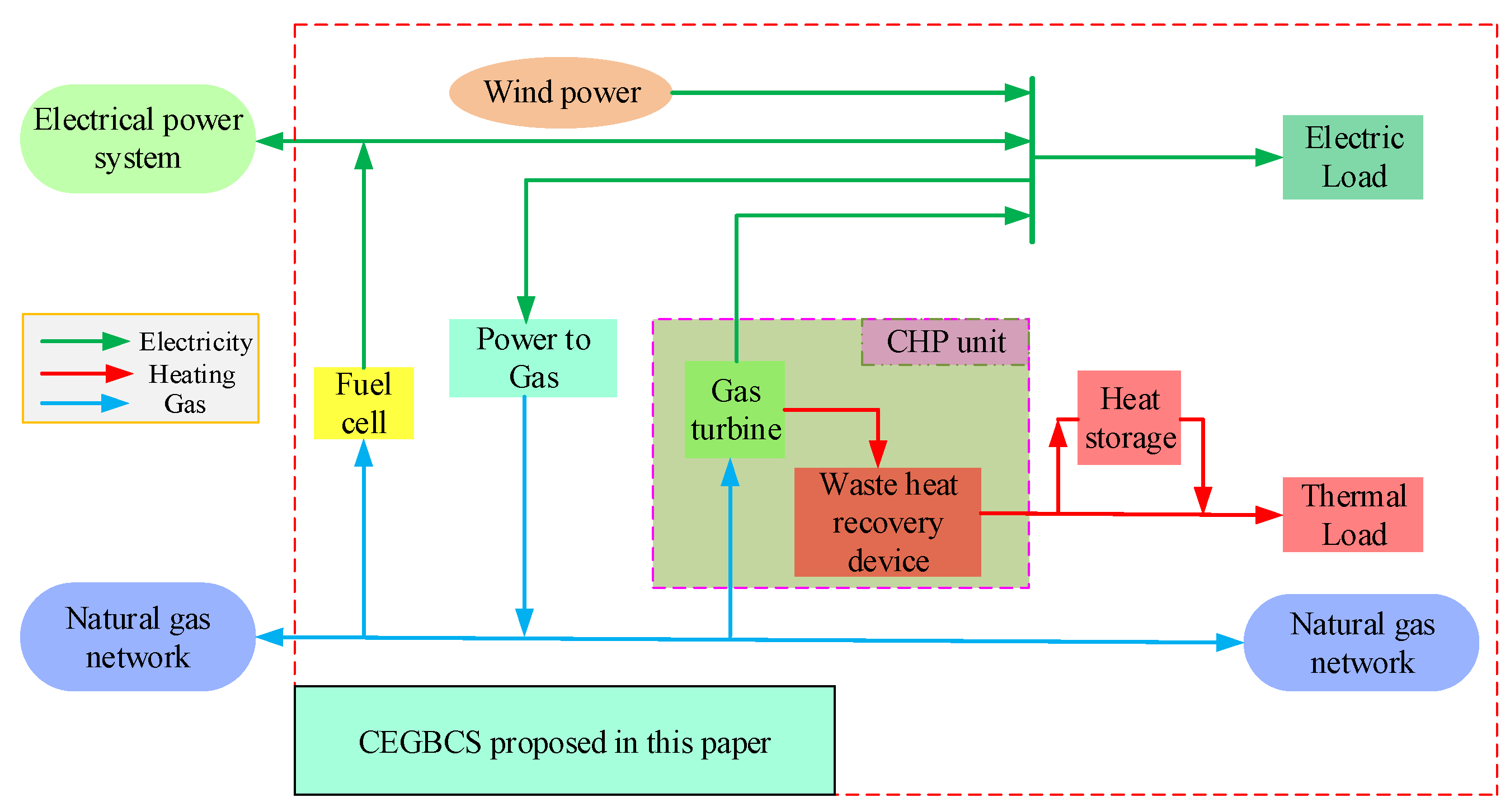
Figure 3.
Principle of decoupling the mode of FTL.

Figure 4.
Principle of decoupling mode of Following the Electric Load (FEL).
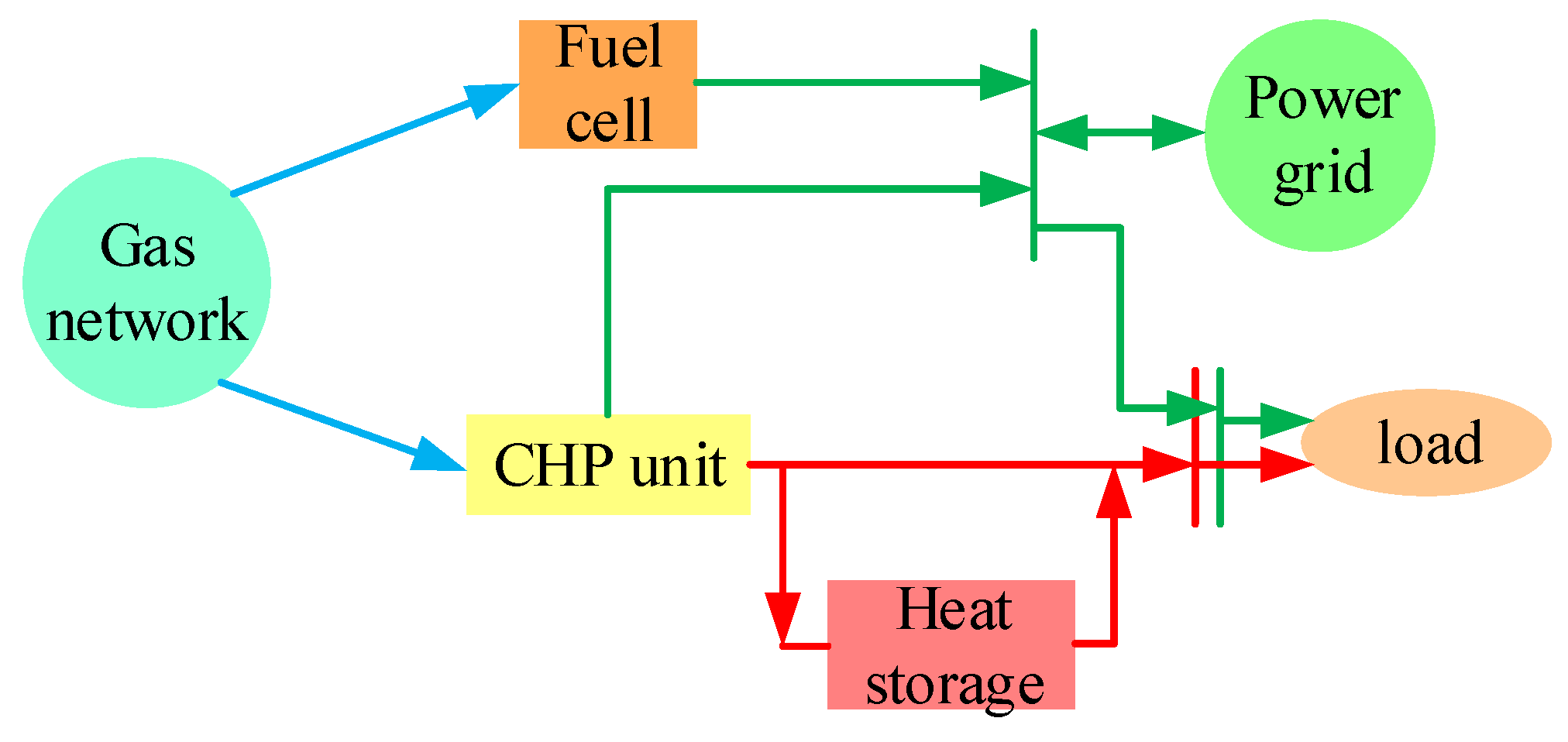
Figure 5.
Combined Electro-Gas Bi-Directional Conversion System (CEGBCS) accommodate wind power by optimization.
Figure 5.
Combined Electro-Gas Bi-Directional Conversion System (CEGBCS) accommodate wind power by optimization.
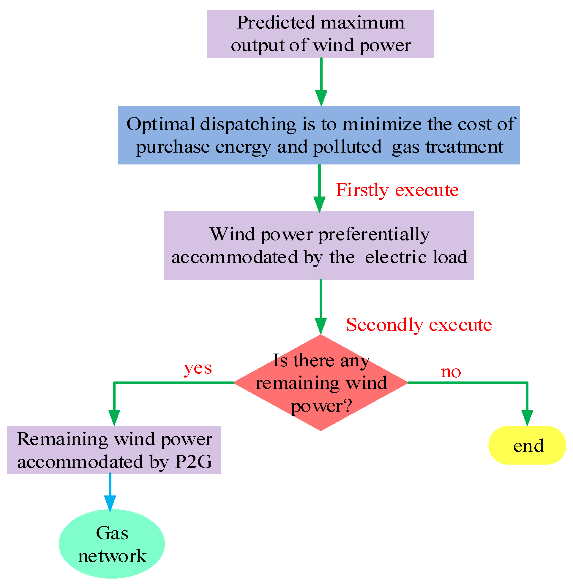
Figure 6.
The time-sharing electricity price of a day.

Figure 7.
Typical daily thermoelectric load curve.

Figure 8.
Maximum output prediction curve of wind power generation without restriction.

Figure 9.
The structure diagram of Scenario 1.
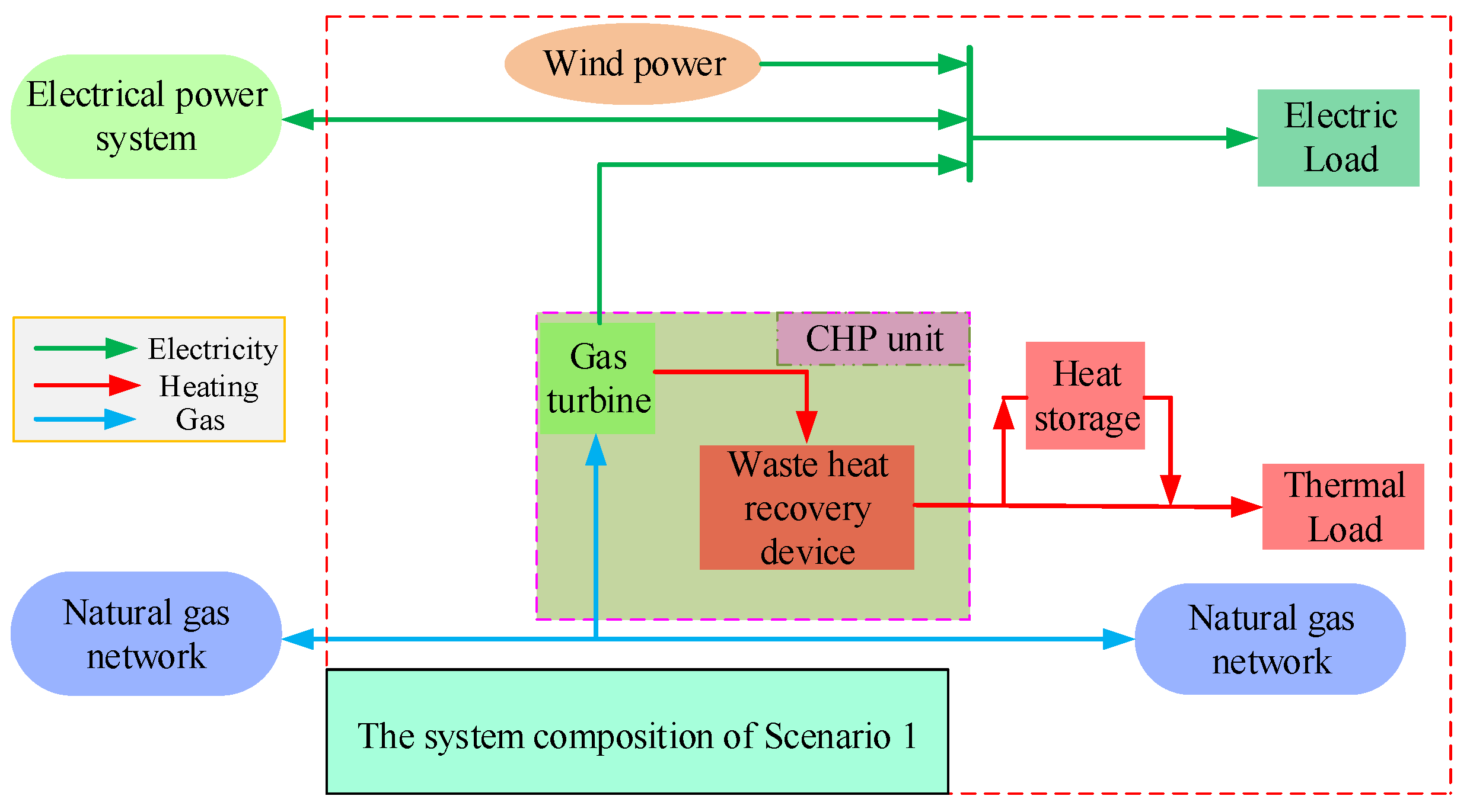
Figure 10.
The structure diagram of Scenario 2.
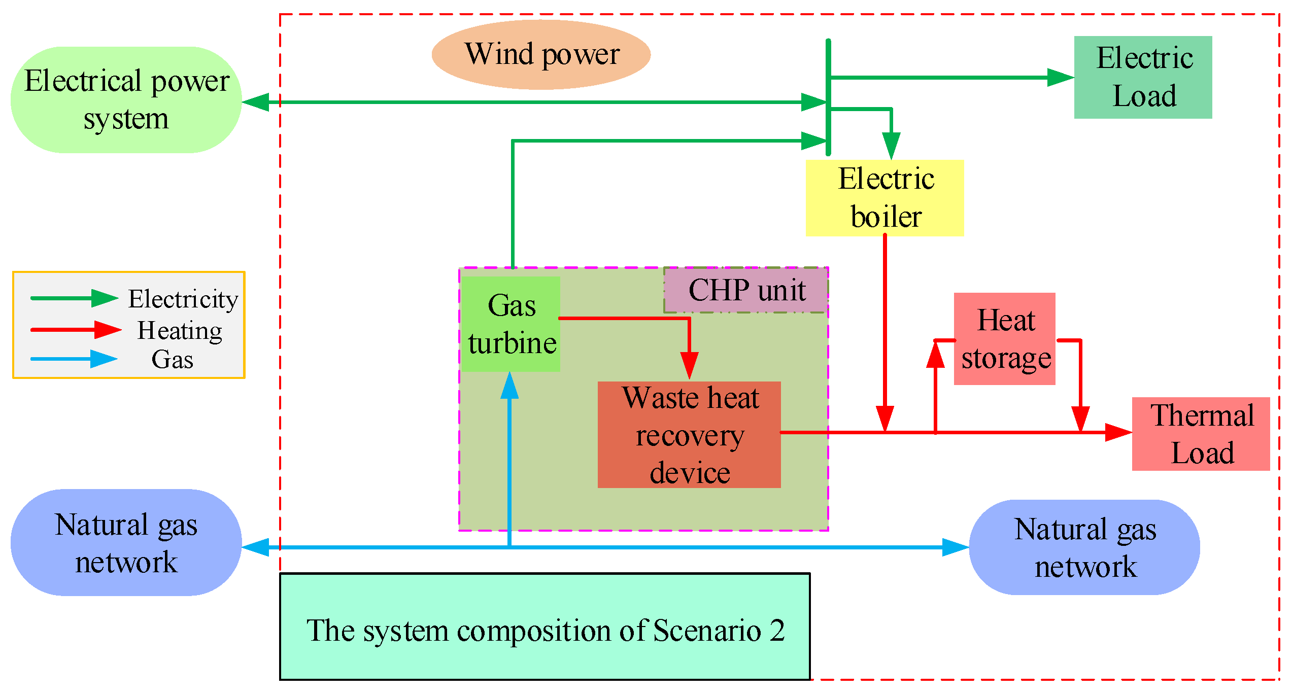
Figure 11.
Wind power consumption by internal load of combined heat and power (CHP) system in different scenarios.
Figure 11.
Wind power consumption by internal load of combined heat and power (CHP) system in different scenarios.

Figure 12.
Energy storage changes of heat storage device in different scenarios.
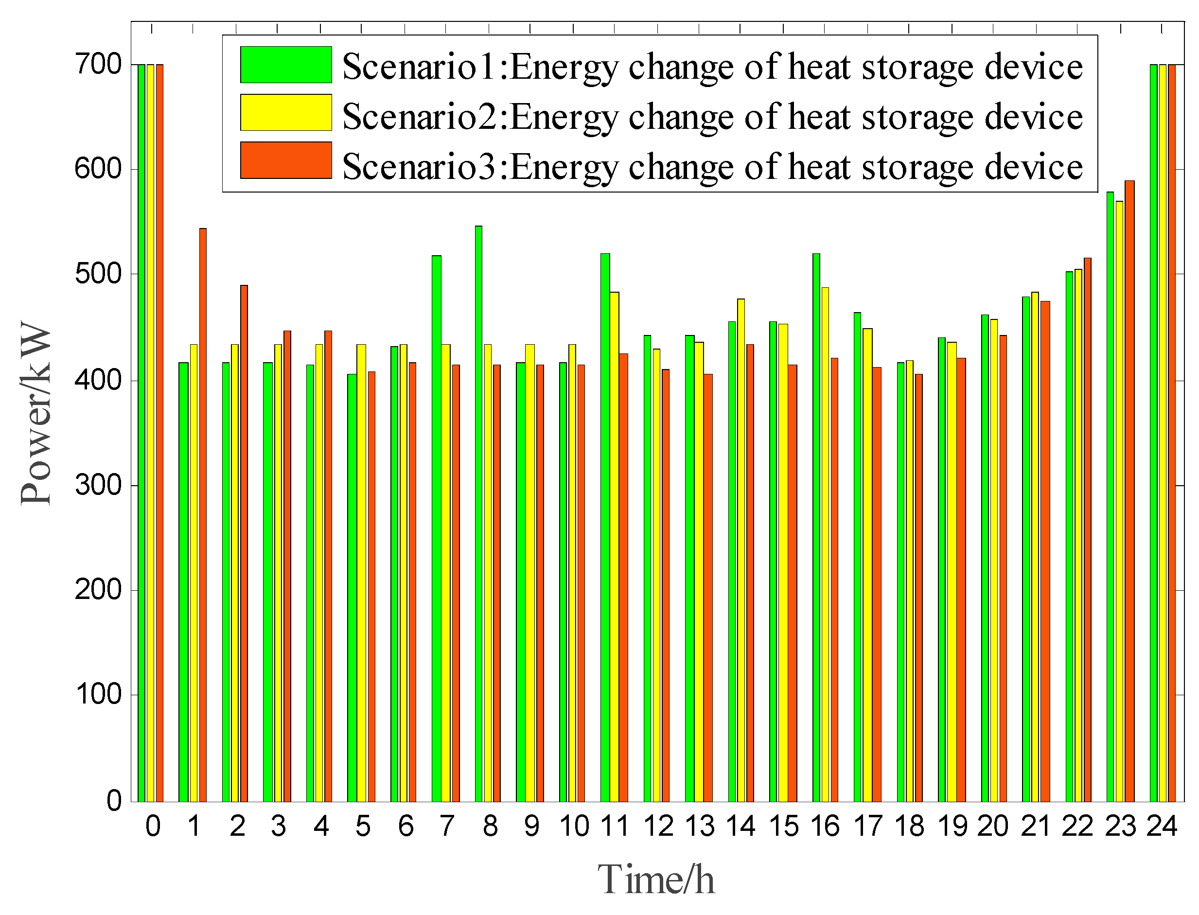
Figure 13.
Output thermal energy of gas turbine in different scenarios.

Figure 14.
Overall wind power consumption of scenario 3.
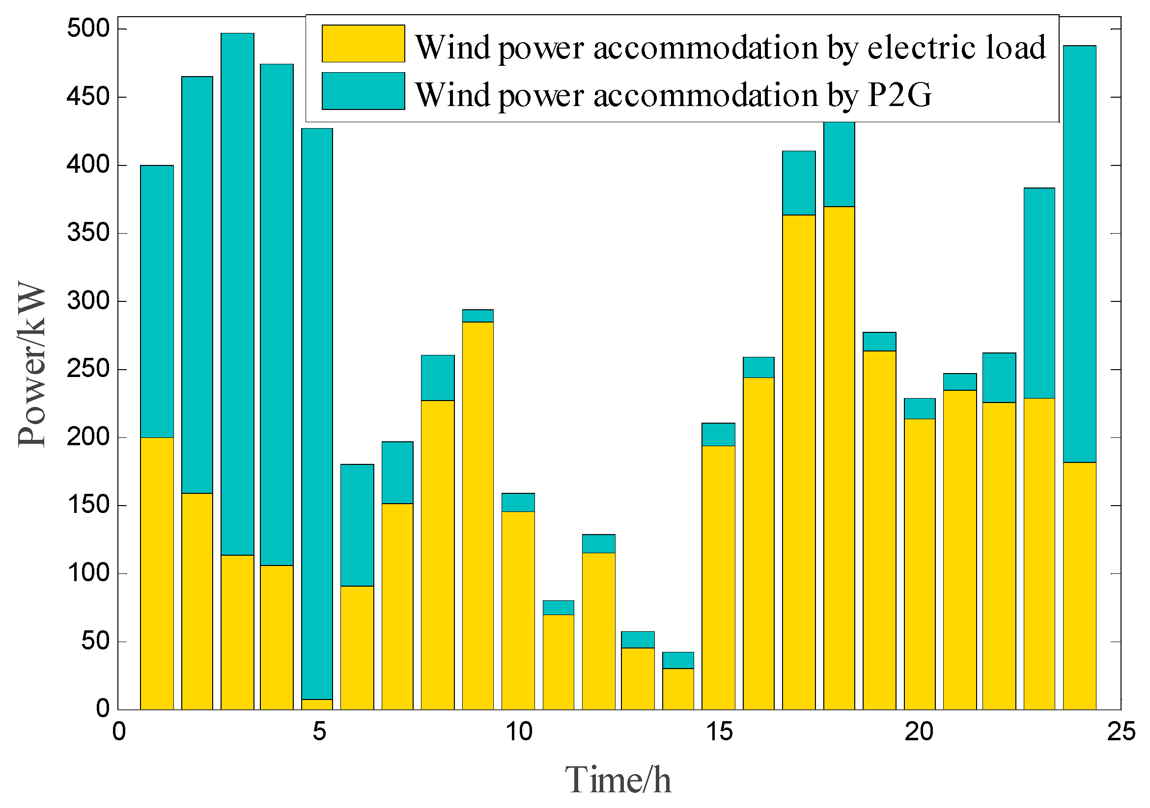
Figure 15.
Electric power dispatch result of each unit in scenario 3.

Figure 16.
Optimal scheduling of heat power in scenario 3.


Table 1.
Simulation Parameters.
| Parameter | Value | Parameter | Value | Parameter | Value | Parameter | Value |
|---|---|---|---|---|---|---|---|
| (kW) | 600 | (kW) | 800 | (kW·h) | 400 | (kW·h) | 1000 |
| 0.98 | 0.98 | 0.002 | (kW) | 1000 | |||
| 0.3 | 1.8 | 0.001 | (kW) | 1500 | |||
| 0.89 | 0.7 | 0.65 | (kW) | 600 | |||
| (kW) | 700 | (yuan/kg) | 0.031 | (kg/(kW·h)) | 0.23 | (kg/(kW·h)) | 0.972 |
| (kW) | 1000 | (kW) | −200 | (kWh/m3) | 9.89 | - | - |
Table 2.
Scenario classification.
| Scene | GT | HB | FC | P2G | EB | WT | HS |
|---|---|---|---|---|---|---|---|
| Scenario 1 | √ | √ | × | × | × | √ | √ |
| Scenario 2 | √ | √ | × | × | √ | √ | √ |
| Scenario 3 | √ | √ | √ | √ | × | √ | √ |
Table 3.
Wind power accommodation by same electric load at different time (kW).
| Time/h | Scenario 1 | Scenario 2 | Scenario 3 | Time/h | Scenario 1 | Scenario 2 | Scenario 3 |
|---|---|---|---|---|---|---|---|
| 0 | 399.82 | 251.60 | 200.30 | 12 | 92.59 | 87.65 | 114.96 |
| 1 | 5.74 | 117.25 | 159.35 | 13 | 36.65 | 4.21 | 44.90 |
| 2 | 15.23 | 107.12 | 112.35 | 14 | 25.34 | 0.22 | 29.95 |
| 3 | 22.15 | 98.87 | 104.91 | 15 | 60.33 | 163.52 | 193.86 |
| 4 | 26.56 | 69.32 | 6.38 | 16 | 29.59 | 207.46 | 243.55 |
| 5 | 40.06 | 41.59 | 90.17 | 17 | 392.54 | 396.82 | 364.17 |
| 6 | 146.36 | 132.04 | 151.77 | 18 | 379.32 | 398.13 | 369.49 |
| 7 | 166.59 | 217.71 | 226.85 | 19 | 233.49 | 251.02 | 263.82 |
| 8 | 263.22 | 266.75 | 284.13 | 20 | 154.25 | 179.45 | 213.81 |
| 9 | 138.20 | 127.54 | 144.81 | 21 | 176.77 | 182.79 | 235.13 |
| 10 | 56.23 | 75.37 | 69.72 | 22 | 201.69 | 180.43 | 225.79 |
| 11 | 399.82 | 251.60 | 200.30 | 23 | 178.31 | 203.51 | 228.11 |
Table 4.
Comparison of operating costs in different scenarios.
| Scene | Scenario 1 | Scenario 2 | Scenario 3 |
|---|---|---|---|
| Cost of electricity purchase/yuan | 10,900 | 11,518 | 4988.4 |
| Cost of gas purchase/yuan | 15,100 | 13,518 | 16,776 |
| Environmental costs/yuan | 739.8541 | 733.8270 | 594.9098 |
| Total cost/yuan | 26,740.8541 | 25,769.827 | 22,359.3098 |
© 2019 by the authors. Licensee MDPI, Basel, Switzerland. This article is an open access article distributed under the terms and conditions of the Creative Commons Attribution (CC BY) license (http://creativecommons.org/licenses/by/4.0/).
Share and Cite
MDPI and ACS Style
Luo, Y.; Yin, Z.; Yang, D.; Zhou, B. A New Wind Power Accommodation Strategy for Combined Heat and Power System Based on Bi-Directional Conversion. Energies 2019, 12, 2458. https://doi.org/10.3390/en12132458
AMA Style
Luo Y, Yin Z, Yang D, Zhou B. A New Wind Power Accommodation Strategy for Combined Heat and Power System Based on Bi-Directional Conversion. Energies. 2019; 12(13):2458. https://doi.org/10.3390/en12132458
Chicago/Turabian StyleLuo, Yanhong, Zhenxing Yin, Dongsheng Yang, and Bowen Zhou. 2019. "A New Wind Power Accommodation Strategy for Combined Heat and Power System Based on Bi-Directional Conversion" Energies 12, no. 13: 2458. https://doi.org/10.3390/en12132458
Note that from the first issue of 2016, this journal uses article numbers instead of page numbers. See further details here.