An Efficient Hybrid Model for Nonlinear Two-Phase Flow in Fractured Low-Permeability Reservoir


1
Beijing International Center for Gas Hydrate, Peking University, Beijing 100871, China
2
Research Institute of Petroleum Exploration & Development, PetroChina, Beijing 100083, China
*
Author to whom correspondence should be addressed.
Energies 2019, 12(15), 2850; https://doi.org/10.3390/en12152850
Submission received: 13 May 2019
/
Revised: 14 July 2019
/
Accepted: 23 July 2019
/
Published: 24 July 2019
(This article belongs to the Special Issue Improved Reservoir Models and Production Forecasting Techniques for Multi-Stage Fractured Hydrocarbon Wells)
Abstract
:The staged fracturing horizontal well has proven to be an attractive alternative for improving the development effect of a low permeability waterflood reservoir. Due to the coexistence of matrix, fracture, and horizontal wellbore, it remains a great challenge to accurately simulate the nonlinear flow behaviors in fractured porous media. Using a discrete fracture model to reduce the dimension of the fracture network, a two-parameter model is used to describe the nonlinear two-phase flow behavior, and the equivalent pipe flow equation is selected to estimate the horizontal wellbore pressure drop in the fractured low-permeability reservoir. A hybrid mathematical model for the nonlinear two-phase flow, including the effect of horizontal wellbore pressure drop in fractured porous media, is developed. A numerical scheme of the hybrid model is derived using the mimetic finite difference method and finite volume method. With a staggered five-spot flood system, the accuracy of the proposed model and the effect of fracture properties on nonlinear two-phase flow behaviors are further investigated. The results also show that with an increase of fracture length near injectors, the breakthrough time of injected water into the horizontal wellbore will be shorter, indicating a faster rise of the water cut, and a worse development effect. The impact of shortening fracture spacing is consistent with that of enlarging fracture length. Successful practice in modeling the complex waterflood behaviors for a 3-D heterogeneous reservoir provides powerful evidence for the practicability and reliability of our model.
1. Introduction
Due to the strong heterogeneity and poor distribution of petrophysical properties, the natural oil productivity of low-permeability reservoirs is extremely low. Currently, the staged fracturing horizontal well has proven to be a viable alternative for improving the development effect of a low-permeability reservoir [1]. In general, the matrix, fracture network and horizontal wellbore are simultaneously distributed in this type of reservoir. However, the fluid flow does not obey the traditional Darcy’s law, which further increases the difficulty of modeling the underlying flow dynamics in fractured porous media. To avoid too-early water breakthrough as much as possible, it is of great importance to establish a hybrid mathematical model for nonlinear two-phase flow, considering the effect of horizontal wellbore pressure drop in the fractured low-permeability waterflood reservoir.
Many attempts had been made to investigate the nonlinear flow characteristics in a low permeability waterflood reservoir, multiphase fluid flow in fractured porous media, optimal design of numerical discretization, and the analysis of variable mass transfer in horizontal wellbore. The commonly used models to describe the nonlinear flow behavior in low-permeability porous media consist of the quasi-threshold gradient model [2], the piecewise nonlinear model [3], and the continuous nonlinear models [4,5,6,7]. Since that the smooth functional relationship is efficient enough to calculate the threshold pressure gradient of nonlinear fluid flow in the subsurface, the continuous nonlinear models, especially the two-parameter model, are growing in popularity among scholars.
Typical models for the representation of fractured porous media generally rely on the dual-porosity model and its extended form (dual permeability model). Those models consider matrix block and fracture network as two parallel continuum systems coupled by crossflow function. Previous studies [8,9,10] have demonstrated that the dual porosity model is not suitable for multiphase flow in disconnected fractured media and mix-wet fracture media. Great trouble will also be encountered when estimating the crossflow function of different systems. To overcome the drawbacks, the discrete fracture model was first introduced for single phase flow by Noorishad and Mehran [11]. The fracture cells are geometrically simplified by using (n − 1)-dimensional cells in an n-dimensional domain, which considerably improved the computational efficiency. The discrete fracture model has been widely employed to investigate the flow mechanism of multiphase fluid in fractured media ever since [12,13,14,15,16,17,18]. On the other hand, strategies for numerical discretization are also key to simulating the complicated flow dynamics in fractured porous media, which mainly include the finite difference (FD) method [19], the finite element (FE) method [8,11], the finite volume (FV) method [20,21], and the mimetic finite difference (MFD) method [22,23,24]. The MFD method, requiring only the node and surface information of single grid cell, is theoretically feasible for any geometry, even the concave grid systems. However, there are limited studies [25,26,27,28] on the nonlinear fluid flow behaviors in fractured low-permeability porous media coupling the MFD method with a discrete fracture model.
The analysis of variable mass transfer in a horizontal wellbore supports insights that predict the production performance, design well trajectory, and optimize well completion parameters. Taking the pressure drop caused by the pipe friction into consideration, Dikken [29] coupled the flux variation in a horizontal wellbore and fluid flow in porous media and then presented a semi-analytical mathematical model, which was then used to calculate the variable mass single-phase pressure drop. Based on extensive theoretical or experimental studies, several analytical models for frictional pressure drop [30,31,32,33,34] have been developed over the last decades. Nevertheless, the accuracy of analysis on the variable mass pressure drop using the analytical models cannot be guaranteed due to the idealized hypothesis. To resolve this issue, the equivalent percolation model of pipe flow was introduced by Wu et al [35] in order to develop a coupled correlation between the variable mass flow in a horizontal wellbore and fluid flow in reservoir. Thereafter, Birchenko et al. [36] and Wang et al. [37] addressed further studies on the equivalent representation models of variable mass flow.
In this study, we aim to propose a novel hybrid mathematical model for two-phase nonlinear flow in fractured low-permeability waterflood reservoir with considering the effect of horizontal wellbore pressure drop. Firstly, using the discrete fracture model to reduce the dimension of fracture network explicitly, the two-parameter model is selected to reflect the nonlinear flow behavior in low-permeability reservoir, and the equivalent percolation model of pipe flow is used to calculate the wellbore pressure drop. Then, a novel mathematical hybrid model for two-phase flow in fractured pore media is established by coupling the governing equations satisfied by matrix, fracture and horizontal well, respectively. Combing the MFD method and FV method, we derive and validate the numerical scheme of the proposed model with a synthetic staggered five-spot flood system. The effect of fracture properties on the nonlinear flow behavior in a fractured low- permeability waterflood reservoir is extensively investigated. Ultimately, the proposed model is applied to a 3-D heterogeneous low-permeability waterflood reservoir to validate its practicability and feasibility.
2. Mimetic Finite Difference Method
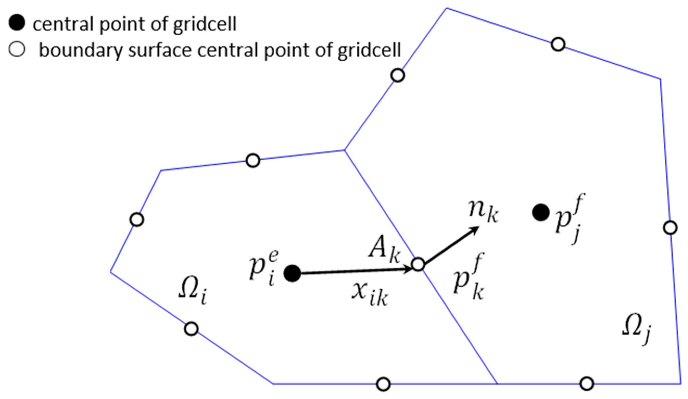
As illustrated in Figure 1, the reservoir area is subdivided by a group of non-overlapping polygon meshes (d = 2) or polyhedron meshes (d = 3) . For arbitrary grid cell , grid is the adjacent grid cell, is the interface, nk is the area-weighted normal vector to face number k. The grid cell pressure and boundary surface pressure are defined at the central point of grid cell and the boundary surface central point of grid cell , respectively, which take the form of.
The total flux normal to the faces can be described as:
where is the transmissibility matrix; ; is the number of borders of grid cell ; . The key to the MFD method is to construct the matrix . A linear pressure field can be obtained in the form for a constant vector a and scalar b. Then the flux and pressure drop are given by
In addition, . By substituting Equation (2) into Equation (3), we can get the following equation.
where , is the unit matrix of d-th order, and is the area of . Then, the matrix can be represented as follows.
where . To guarantee the existence of inverse of , the Brezzi-Lipnikov-Simoncini theorem [38] is used to construct the matrix :
where , and A is the diagonal matrix with Ai (i.e., the face area of the ith face)
Based on the divergence theorem and the integral procedure on arbitrary grid cell , the following equation can be obtained.
Considering the flux continuous condition of boundary, numerical scheme of the MFD method is established ultimately by coupling Equations (2) and (7).
where ; ; ; , and . Noting that, the first row of Equation (8) denotes the Darcy’s law, the second row denotes the mass conservation, and the third row denotes the normal flux continuous condition of borders. Coefficient matrices of Equation (8) can be written as:
where is the total number of grid cells; . As can be seen from Equation (9), all the coefficient matrices of Equation (8) are subjected to the petrophysical properties and geometric information of grid cells, but insensitive to the geometric shape.
3. Hybrid Model for Two-Phase Flow in Fractured Media
Using the discrete fracture model to reduce the dimension of the fracture network explicitly, the two-parameter model is used to reflect the nonlinear flow behavior of two-phase fluid, and the equivalent percolation model of pipe flow is selected to calculate the wellbore pressure drop of the horizontal well. Ultimately, a hybrid mathematical model for two-phase flow in a fractured low-permeability waterflood reservoir is established by combing the governing equations satisfied by the matrix, fracture and horizontal well, respectively.
3.1. Discrete Fracture Model
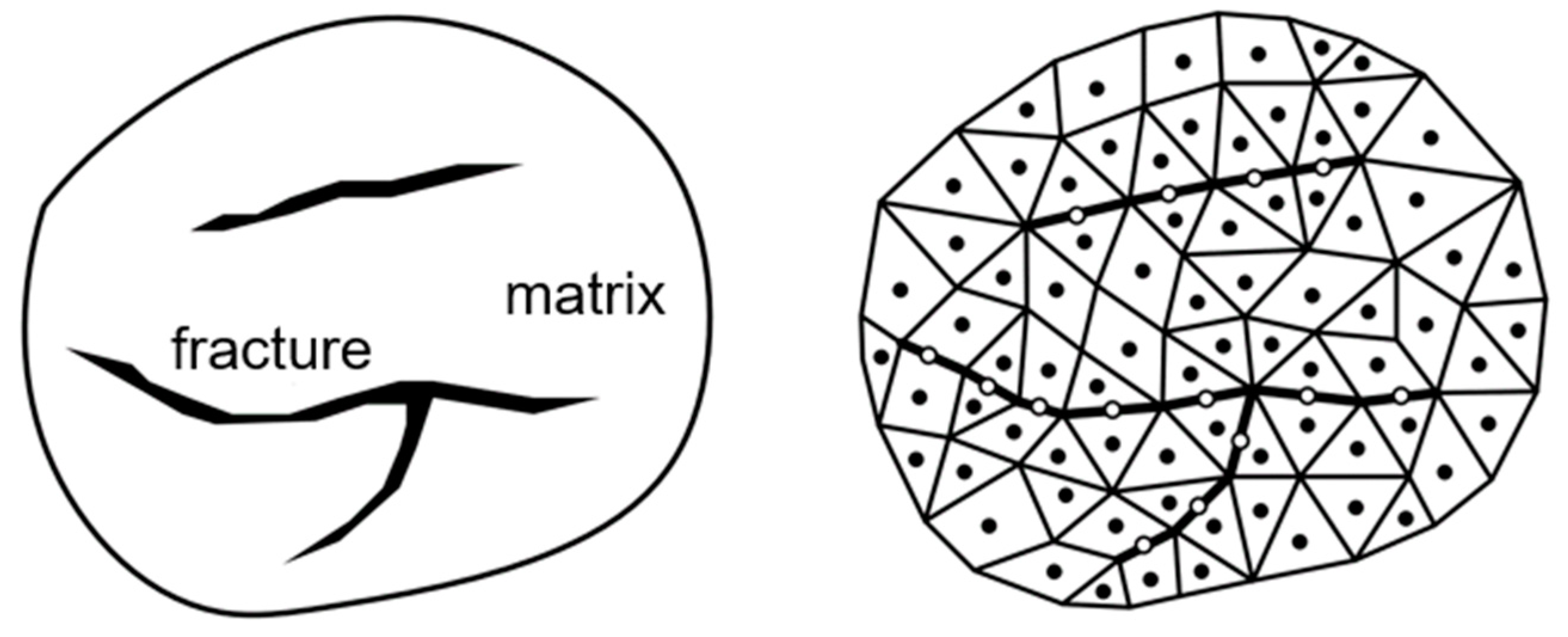
As previously suggested [11], fluid flow through fractures can be modelled as a laminar flow between parallel plates. The parallel-plate solution for the Naiver-Stokes equations satisfies the commonly used law that flow rate is proportional to the cube of the fracture aperture. All the variables remain constant along the direction of fracture aperture. Therefore, the dimension-reduced processing of a fracture network by using (n − 1)-dimensional grid cells in an n-dimensional domain greatly improves the computational efficiency. In 2D space, fracture networks are simplified as line elements (see Figure 2). In 3D space, the fractures are represented by the matrix grid cell interfaces, which are 2D. In this study, the Delaunay triangulation method is adopted to establish the grid system.
As shown in Figure 2, the fractured media is composed of matrix and fracture simultaneously, and the whole domain can be expressed as , where the subscripts m and f denote the matrix and fracture, respectively; ai is the aperture of the ith fracture. Only if the representative elementary volumes (REV) of matrix and fracture exist, the constituents of flow equations F are feasible to the whole domain. For the discrete fracture model, the integral form of F is described as.
3.2. Flow Governing Equations
The basic equations of incompressible two-phase flow include the mass conservation equation, the generalized Darcy’s law, the saturation equation and the capillary pressure function, which are described as:
where is the porosity; vo and vw are the oil and water velocity, respectively, and total velocity , m/s; qo and qw are the source/sink term of oil and water, respectively, and total source/sink term , 1/s; (l = w, o) is the flow coefficient, and total flow coefficient ; is the water fractional flow function; ρo and ρw are the oil and water density, respectively, kg/m3; is the gravitational force term, and is the gravity acceleration, m/s2; is the vertical coordinate with positive direction upward, m; is the capillary pressure, Pa; po and pw are the pore pressure for oil and water, respectively, Pa; So and Sw are the oil and water saturation, respectively.
Defining the flow potential function , the initial and boundary conditions are written as follows.
(i) Initial conditions
(ii) Dirichlet boundary conditions
(iii) Neumann boundary conditions. The boundary conditions used in this paper are assumed to be impervious.
where denotes the outer normal unit vector.
3.3. Description of Nonlinear Fluid Flow
The two-parameter model is used to describe the nonlinear flow behavior of multiphase fluid in porous media and takes the form of.
where b is the reciprocal of quasi-threshold pressure gradient, 10−6(Pa/m)−1; a is a dimensionless parameter to determine the shape of nonlinear concave curve segment, a > 0. Both parameters can be obtained from displacement experiments. When the dimensionless parameter a is equal to zero, the model is equivalent to the quasi-threshold pressure gradient model, among which, the nonlinear seepage segment satisfy the linear law and its intersection with x-axis is located at 1/b; when a is larger than zero and less than 1.0, the intersection with x-axis is located at (1 − a)/b, which is virtually the minimum threshold pressure gradient. When b tends to be infinite, the interaction between rock and reservoir fluid is so weak that it equals to zero approximately. In this case, Equation (20) will be transformed as the Darcy’s law.
3.4. Calculation of Wellbore Pressure Drop
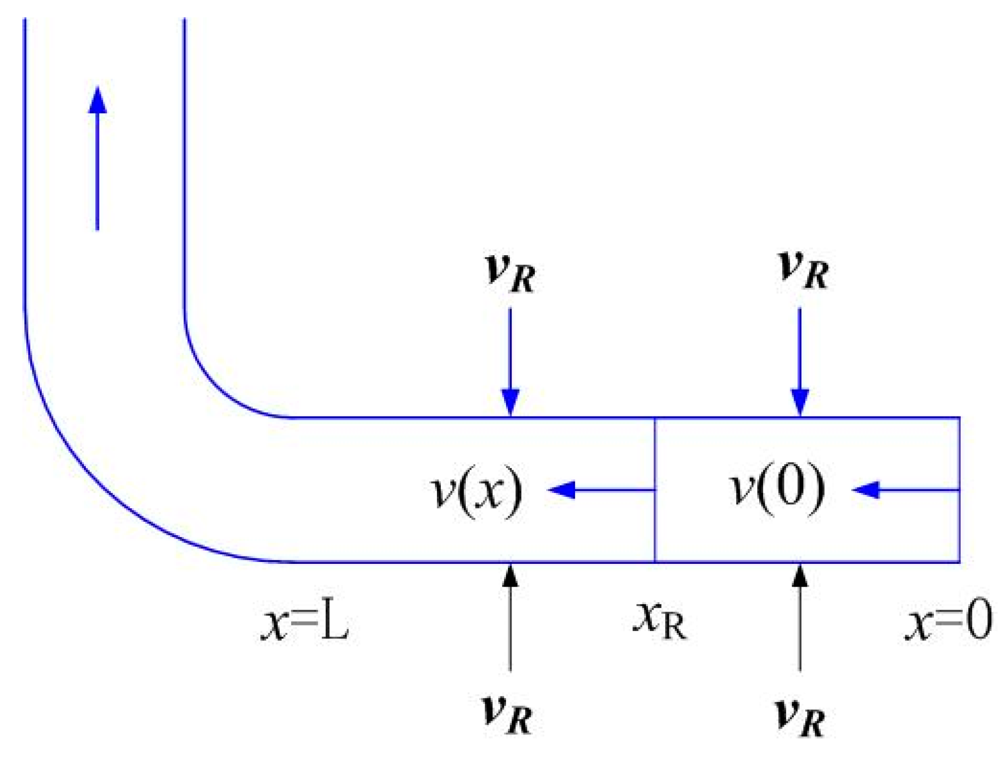
Generally, the flow regime in horizontal wellbore consists of the spindle flow in horizontal wellbore and the radial flow from reservoir to horizontal well. Due to the radial flow, the flux of lateral segment from toe end to root end varies gradually, in other words, it is a variable mass flow, which is shown as Figure 3, where denotes the mass flux of the radial flow from reservoir to horizontal well and denotes the variable mass flux of the spindle flow in horizontal wellbore.
In this study, the equivalent percolation model of pipe flow is employed to calculate the pressure drop caused by variable mass flow in horizontal wellbore. Namely, the pipe flow can be interpreted as an equivalent seepage problem with constant permeability. Equation (21) is thus proposed to describe the relationship.
where Kwe is the equivalent permeability of horizontal wellbore.
For laminar flow
For turbulent flow:
where the fraction factor f can be calculated by Colebrook-White equation and satisfies the following equation.
For transitional flow:
where is the weighting coefficient, [0.1, 0.3]; Kwel is the equivalent permeability in procedure of lamilar flow; Kwet is the equivalent permeability in procedure of turbulent flow.
3.5. Hybrid Mathematical Model
The novel hybrid model for nonlinear two-phase flow in fractured porous media is established by combining the governing equations satisfied by matrix, fracture and horizontal wellbore, respectively.
For the matrix system, considering that nonlinear flow behavior in fractured low-permeability reservoir, the following equation is given by:
For the fracture system, the dimension-reduced procedure of the fracture network by using (n − 1)-dimension grid cells in an n-dimensional domain is carried out. Assume that flow in fracture observes the standard Darcy’s law, the system of Equations (11)–(16) is still suitable.
For the horizontal wellbore, the equation describing the correlation between velocity v and pressure p is given by:
When considering the pressure drop in horizontal wellbore, the flux continuous condition of horizontal wellbore is derived as follows.
where is flux from the upward matrix grid cell E to the ith lateral segment; is flux from the downward matrix grid cell E′ to the ith lateral segment; is flux from the upward fracture grid cell F to the ith lateral segment; is flux from the downward fracture grid cell F′ to the ith lateral segment; is total flux penetrated into the ith lateral segment; is the total flux; is the source or sink term.
4. Numerical Discretization and Solution
Using the MFD method, numerical discretization of the hybrid mathematical model is performed in order to obtain the pressure and saturation distribution as a function of time in fractured low-permeability waterflood reservoir according to the implicit pressure and explicit saturation (IMPES) procedure.
4.1. Numerical Discretization
Based on the mimetic finite difference method, the linear algebraic systems satisfied by matrix block and fracture network are finally established, which are written as Equations (29) and (30), respectively. As to 2D problems, due to the fracture networks being simplified as a series of line elements, the governing equations can be described as:
where the subscripts m and f are matrix and fracture system, respectively.
The system given in linear algebraic equations indicates that pf is a part of πm. Based on the flux continuity principle, the volumetric flux of fracture system is composed of matrix infiltration and fracture source or sink term. By coupling the flow equations between the matrix and fracture systems, numerical discretization is achieved, which is given by:
When matrix, fracture, and horizontal wells exist simultaneously, the equivalent percolation model of pipe flow is used to calculate the wellbore pressure drop, and the total volumetric flux in horizontal wellbore is composed of matrix infiltration, fracture infiltration and source or sink term. In accordance with Equation (31), numerical discretization scheme of the hybrid mathematical model can be developed combining the flow equations satisfied by the matrix, fracture, and horizontal wellbore, respectively, and takes the form of:
where subscript h denotes the horizontal well; denotes the boundary flux of matrix grid cell; denotes the pressure at the central point of matrix grid cell; denotes the boundary pressure of matrix grid cell; denotes the boundary flux of fracture grid cell; denotes the boundary pressure of fracture grid cell; denotes the boundary flux of horizontal well grid cell; denotes the boundary pressure of horizontal well grid cell.
4.2. Solution of Pressure and Saturation
The implicit pressure explicit saturation (IMPES) procedure is used for calculation, which mainly include the sequential solution of the decoupled pressure and saturation equations. The pressure equations are solved implicitly with the preconditioned conjugate gradient and the saturation maps are determined explicitly using the FV method.
According to the FV method and θ-principle, discretization of mass conservation equation given by Equation (11) is performed, which is described as:
where is the numerical approximation of flux at the edge .
Moreover, the upstream weighted method is used to calculate the fractional flow function at boundary surface .
The time step is determined by a CFL condition, which is described as follows:
and
where S* is the standardized water saturation; Swc is the irreducible water saturation; Sor is the residual oil saturation.
5. Results and Analysis
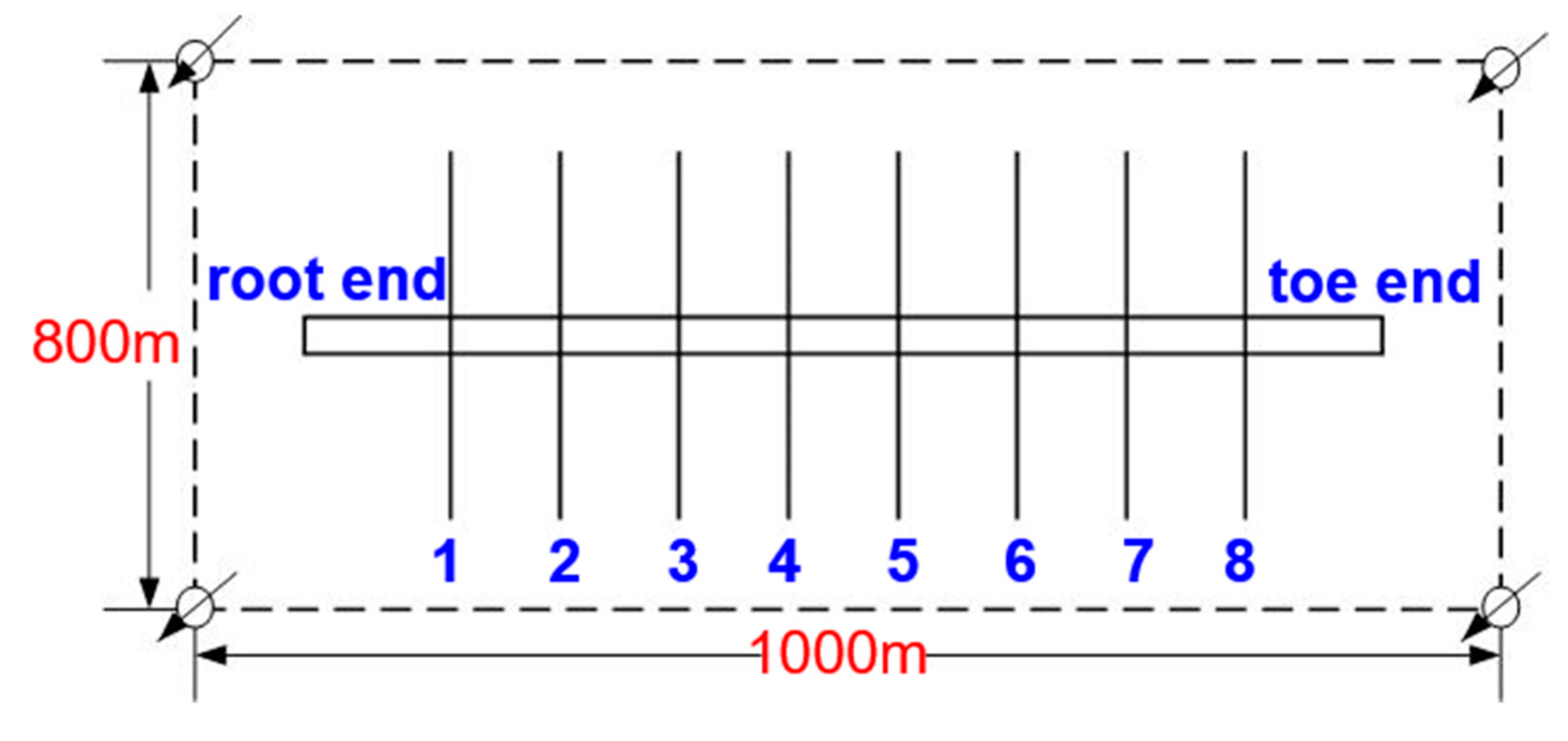
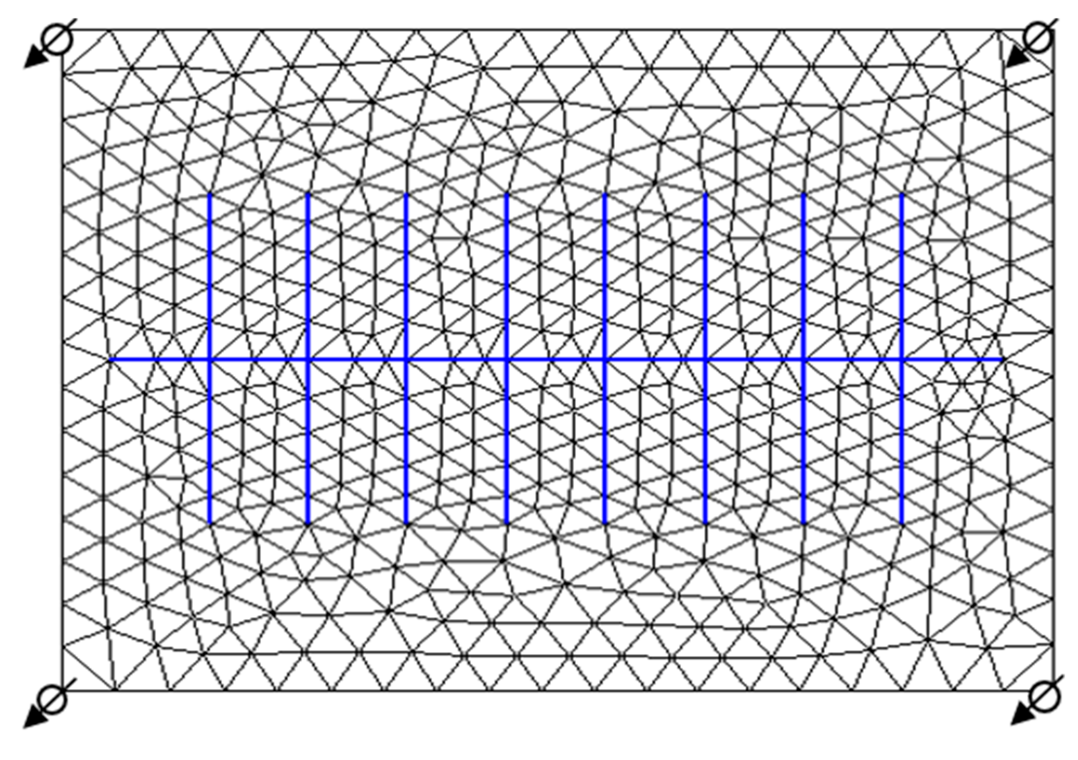
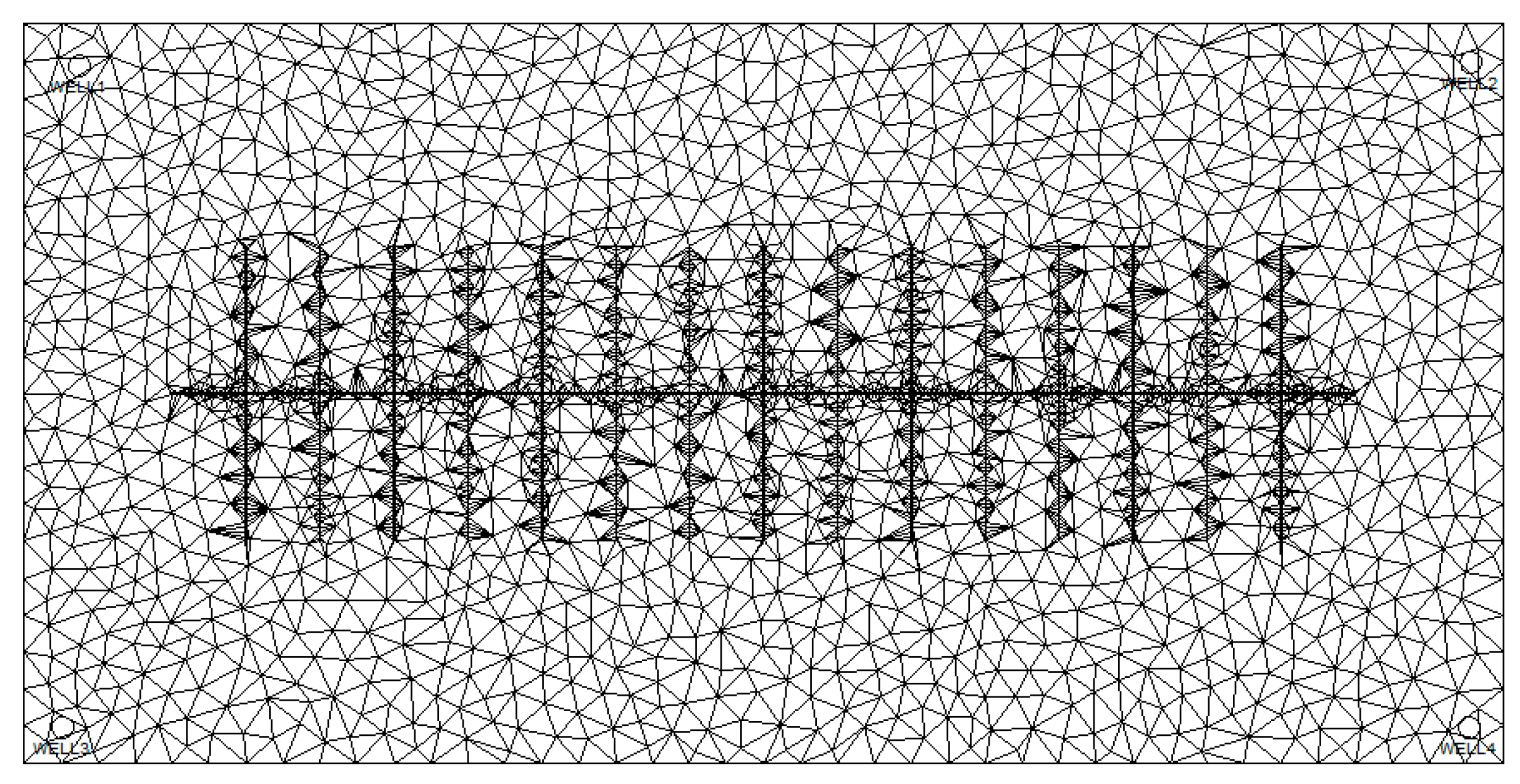
We use a synthetic two-dimensional staggered five-spot flood system to validate the accuracy of the proposed model in this paper, as shown in Figure 4. The Delaunay triangulation grid system shown as Figure 5 is firstly constructed, with a total of 994 grid cells. The rock and fluid properties are listed in Table 1. The well pattern is one staged fracturing horizontal producer located in the center face and four vertical injectors located in corner faces. Both the injection and production are performed at a constant surface liquid rate, which are the same as the controlling conditions in actual oilfield development. There exist eight hydraulic fractures distributed evenly along the direction of the horizontal wellbore. The effects of capillary pressure and gravitational force will be neglected.
The oil-water relative permeability functions shared by the matrix and fracture systems are described as follows.
where Se is the normalized water saturation defined by the irreducible water saturation Swc and the residual water saturation Sor, which takes the form of.
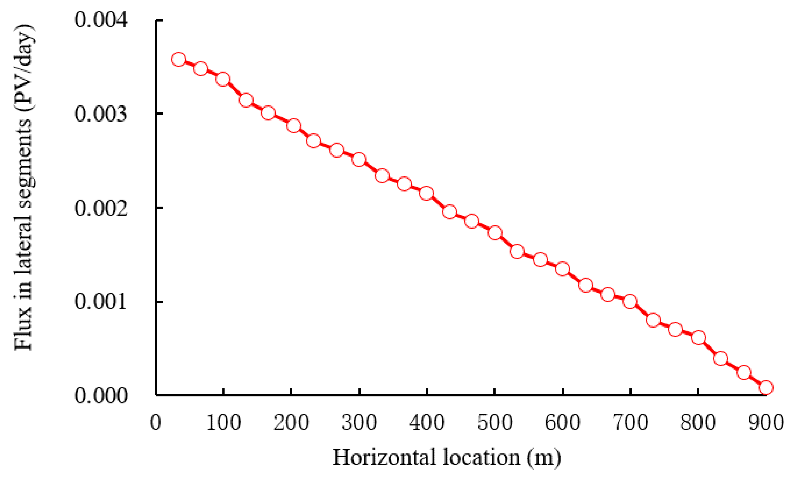
Figure 6 displays the flux of different lateral segments in horizontal wellbore. It can be referred that the mass flux in horizontal wellbore gradually increases from the toe end to the root end, and there is a distinct difference in the mass flux of different lateral segments due to the variable mass flow. The effect of fracture distribution on the mass flux change in the horizontal wellbore is relatively large.
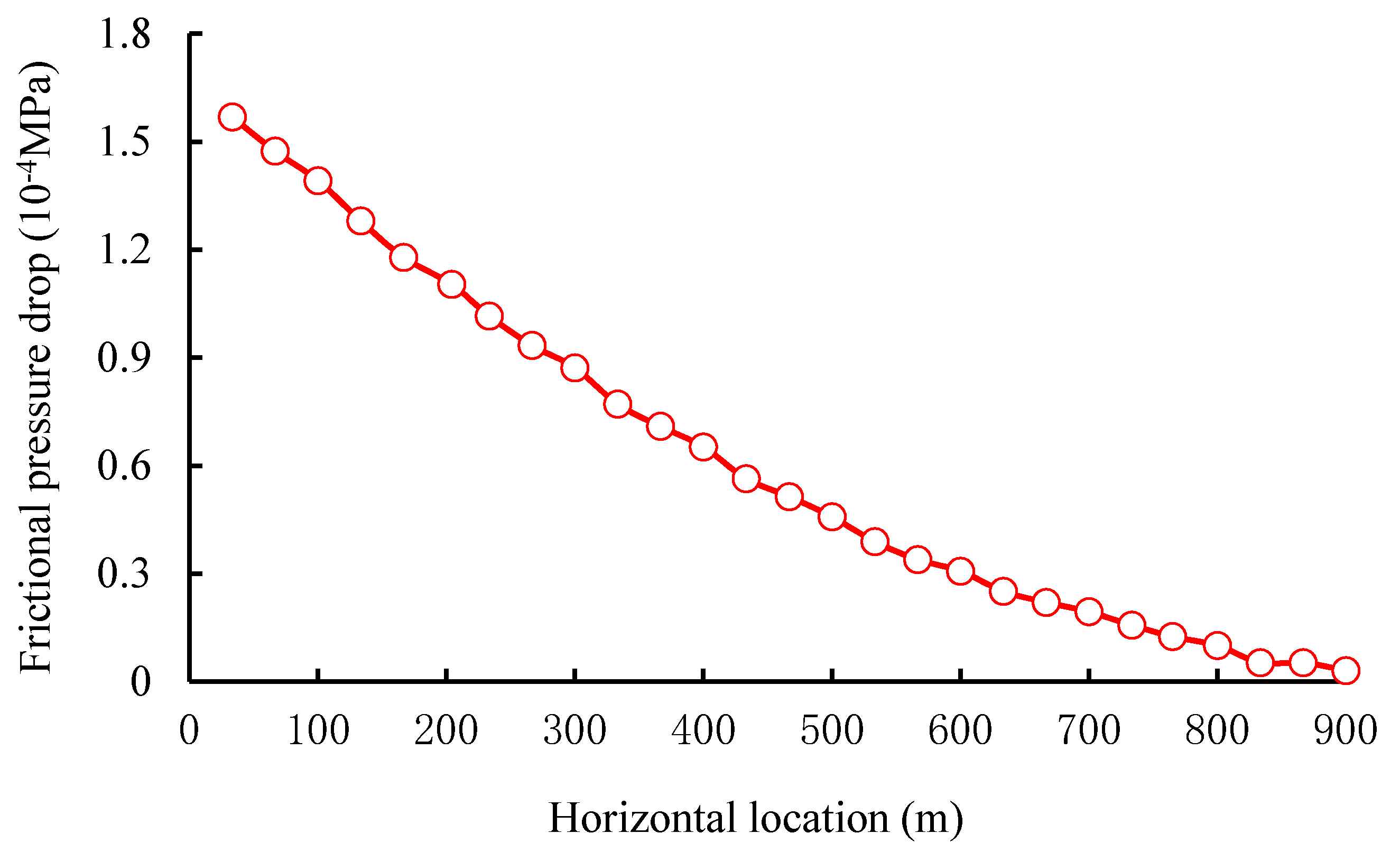
Figure 7 shows the distribution of friction pressure drop along direction of horizontal wellbore. It indicates that, the change of friction pressure drop from the toe end to root end is consistent with the mass flux of different lateral segments in horizontal wellbore. The main reason for this phenomenon is explained as follows: the variation of the friction pressure drop is proportional to that of the variable mass flux, and the frictional pressure drop caused by the spindle flow and the radial flow is aggravated as the variable mass flux increases. In addition, due to the great infiltration at the fractures’ face, the degree of velocity variation is further improved, which usually results in a greater frictional pressure drop.
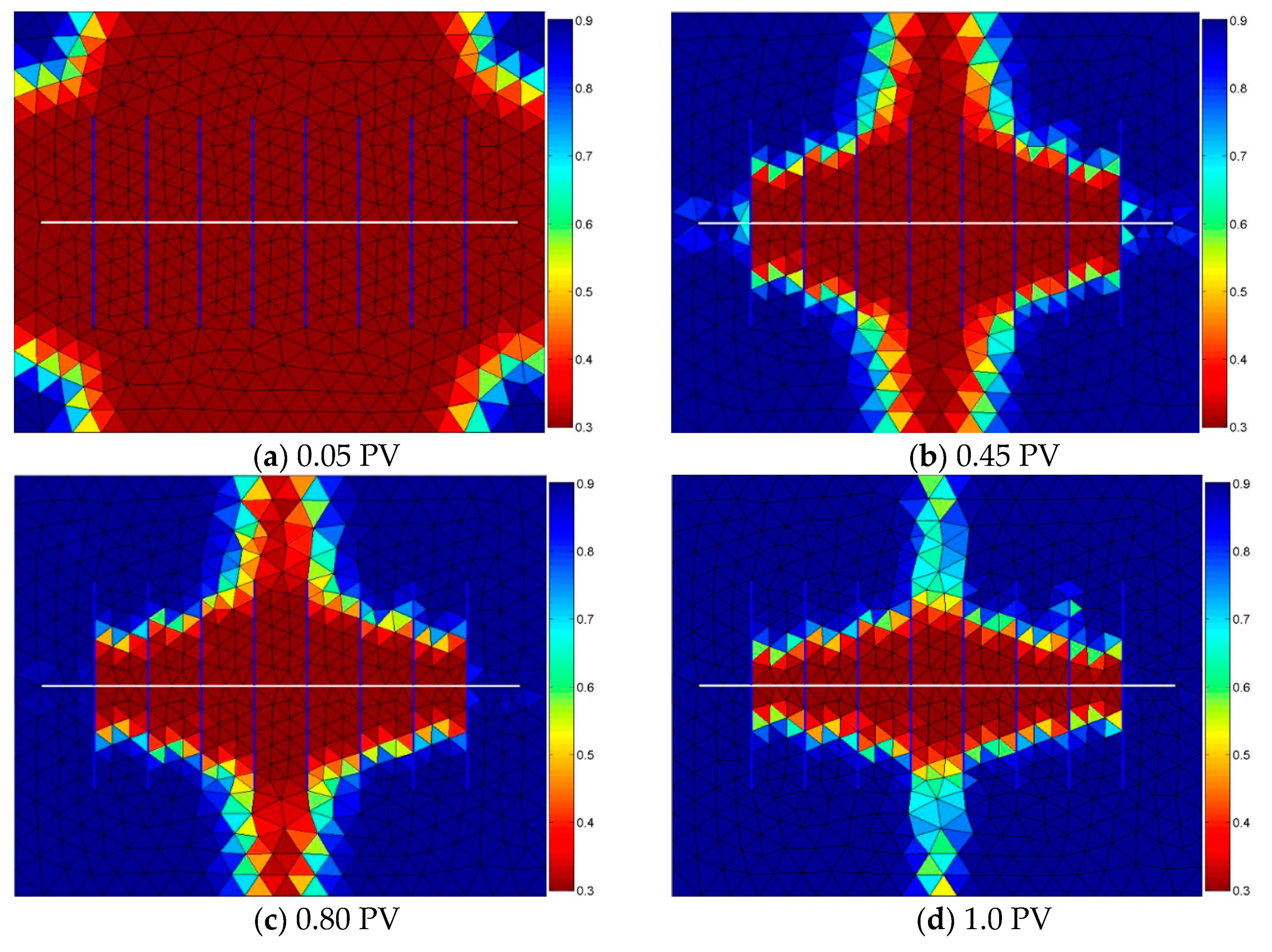
As shown in Figure 8, we present the water saturation profiles when the pore volume of water injected into the reservoir is fixed at 0.05, 0.45, 0.80 and 1.0 PV, respectively. The results demonstrate that the waterflood front advances evenly at the earlier stage, while the injected water will transport quickly through the fractures and cause too-early water breakthrough. When the injected water crosses into all the fractures, large quantities of residual oil remain unexploited between the fractures. The fractures nearby the injectors are the major flow pathways of injected water to the staggered fractured horizontal wellbore, which govern the local velocity of waterfront directly. Therefore, the middle regions’ fractures along the direction of the horizontal wellbore are extremely essential to achieve a higher oil productivity in the fractured low-permeability waterflood reservoir.
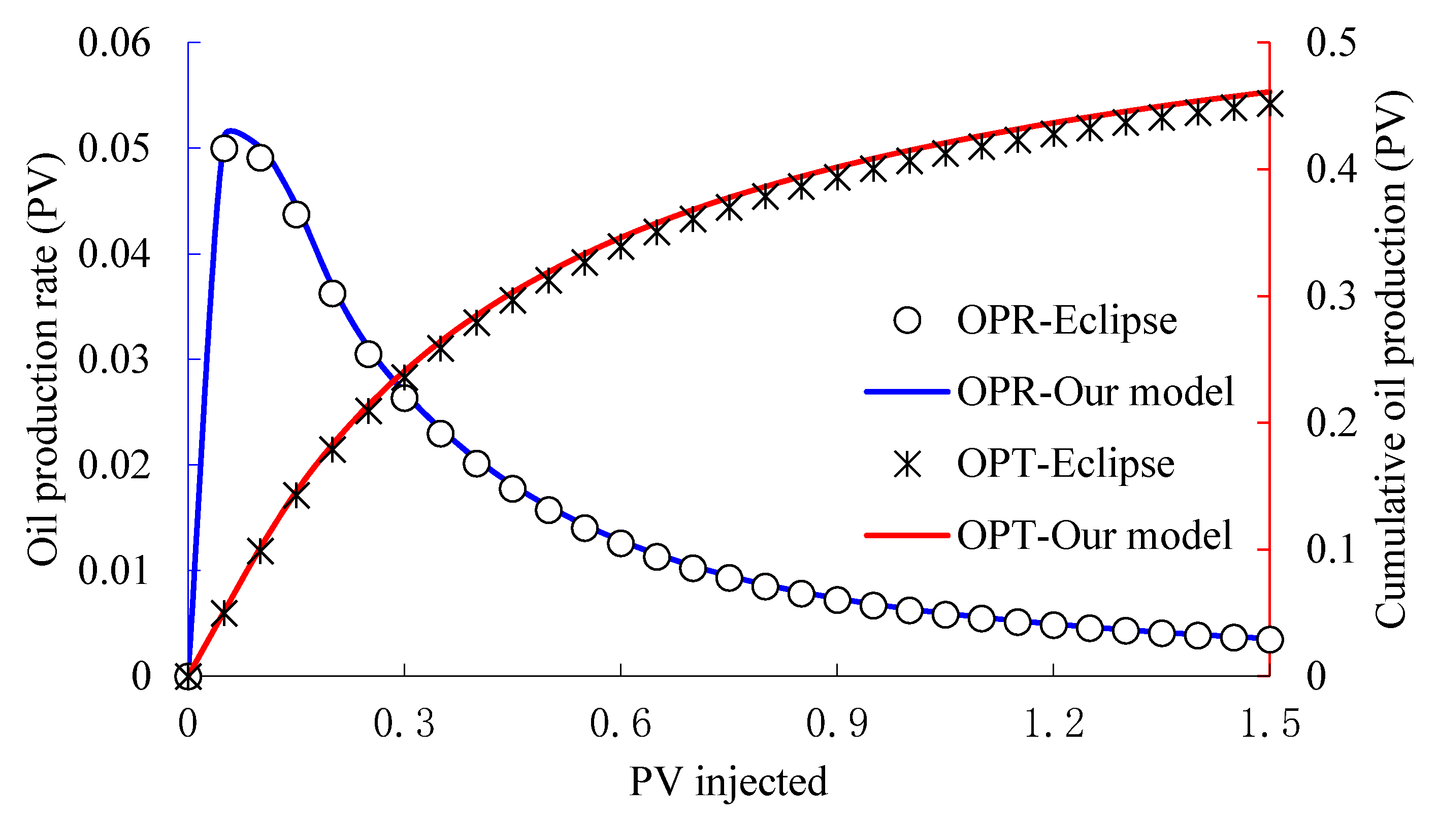
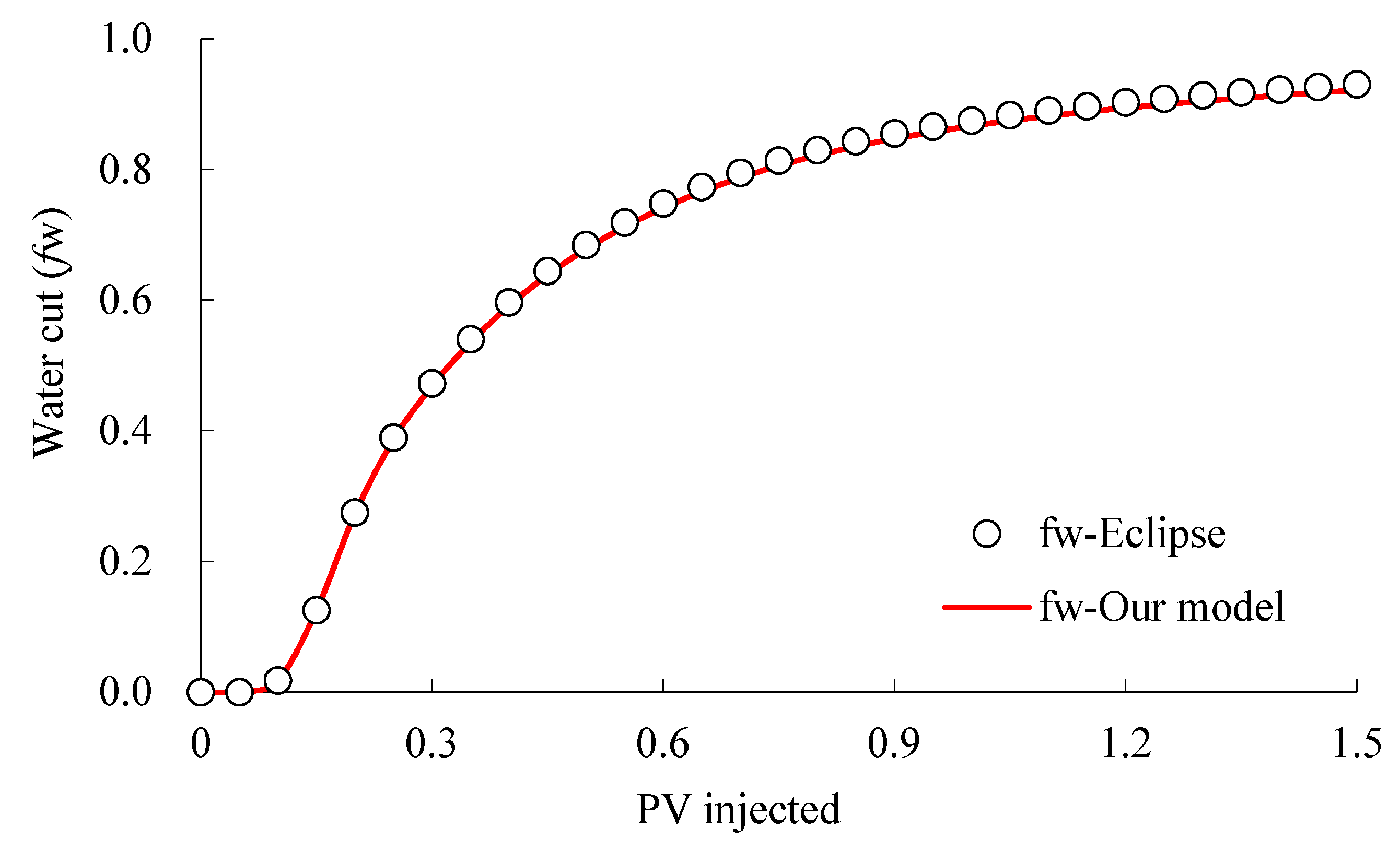
A comparison of oil production rate (OPR), cumulative oil production (OPT) and water cut (fw) as a function of PV injected is displayed in Figure 9 and Figure 10. The accuracy of our proposed model has been validated by comparing with Eclipse. Results also demonstrate that oil production rate of the staged fracturing horizontal well at the earlier stage is relatively high, and the rising rate of cumulative oil production is rapid. However, the oil production rate gradually decreases as the waterfront advances in low-permeability porous media. When a total of 0.5 PV water is injected into the reservoir, the oil production rate tends to be constant, and the increase of cumulative oil production becomes slight. It is due to the short distance between end regions’ fractures and injectors that water can channel into the horizontal wellbore along the fractures quickly, thus resulting in a rapid rise of water cut. Therefore, the fracture properties are governing factors for the development effect of a staged fracturing horizontal well in a low-permeability waterflood reservoir.
5.1. Effect of Fracture Length
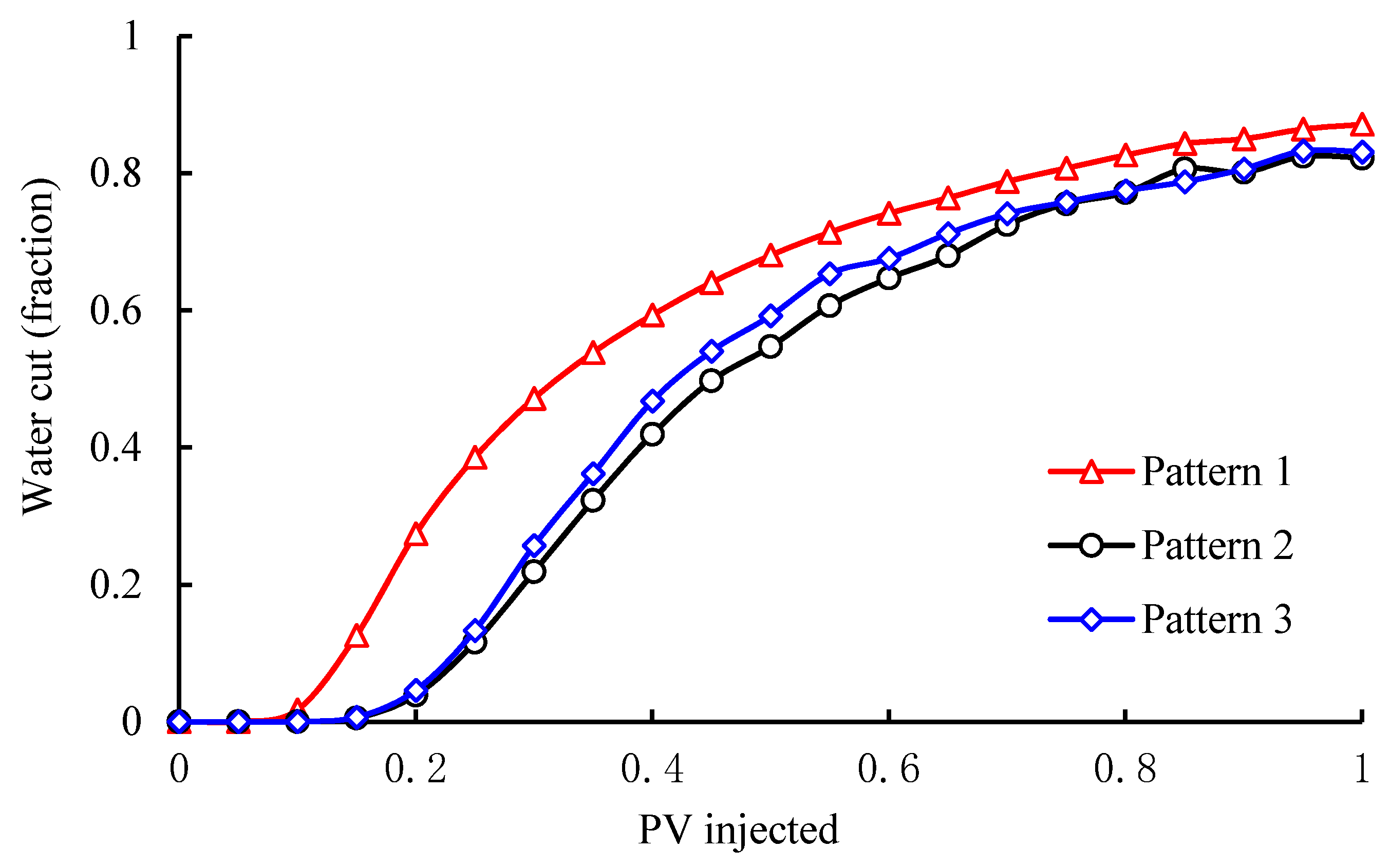
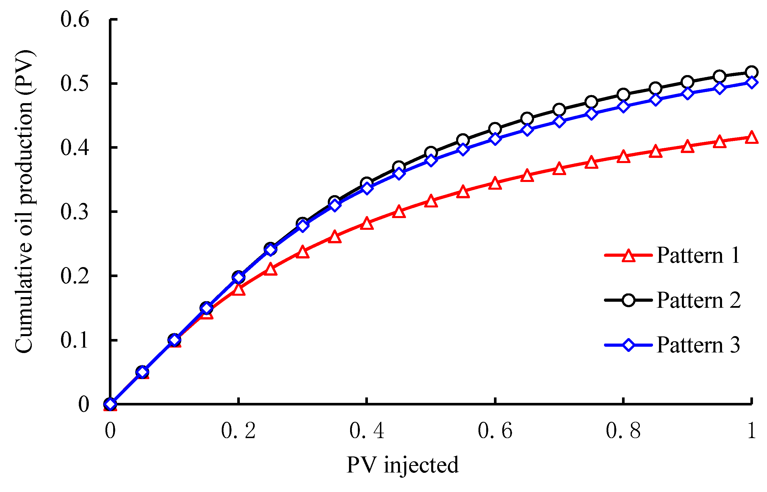
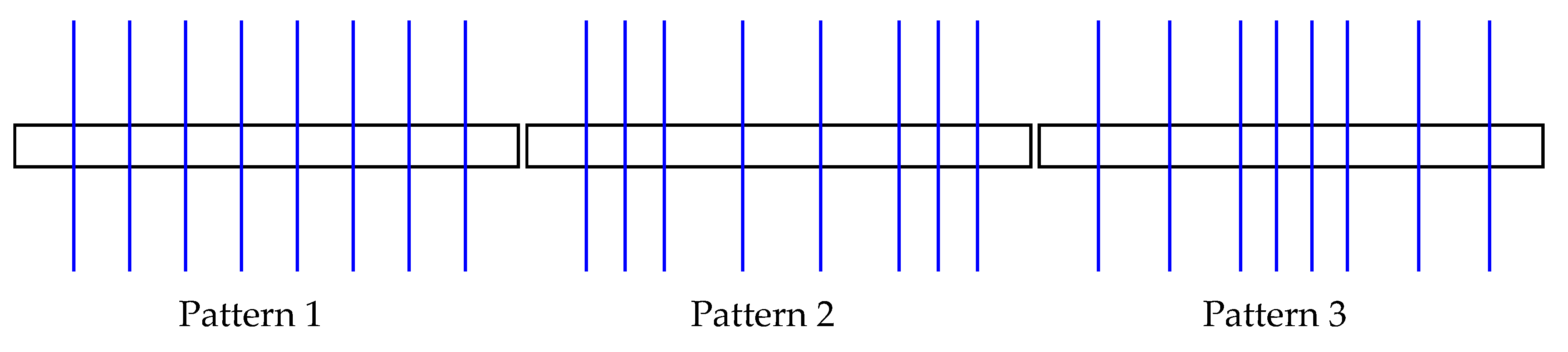
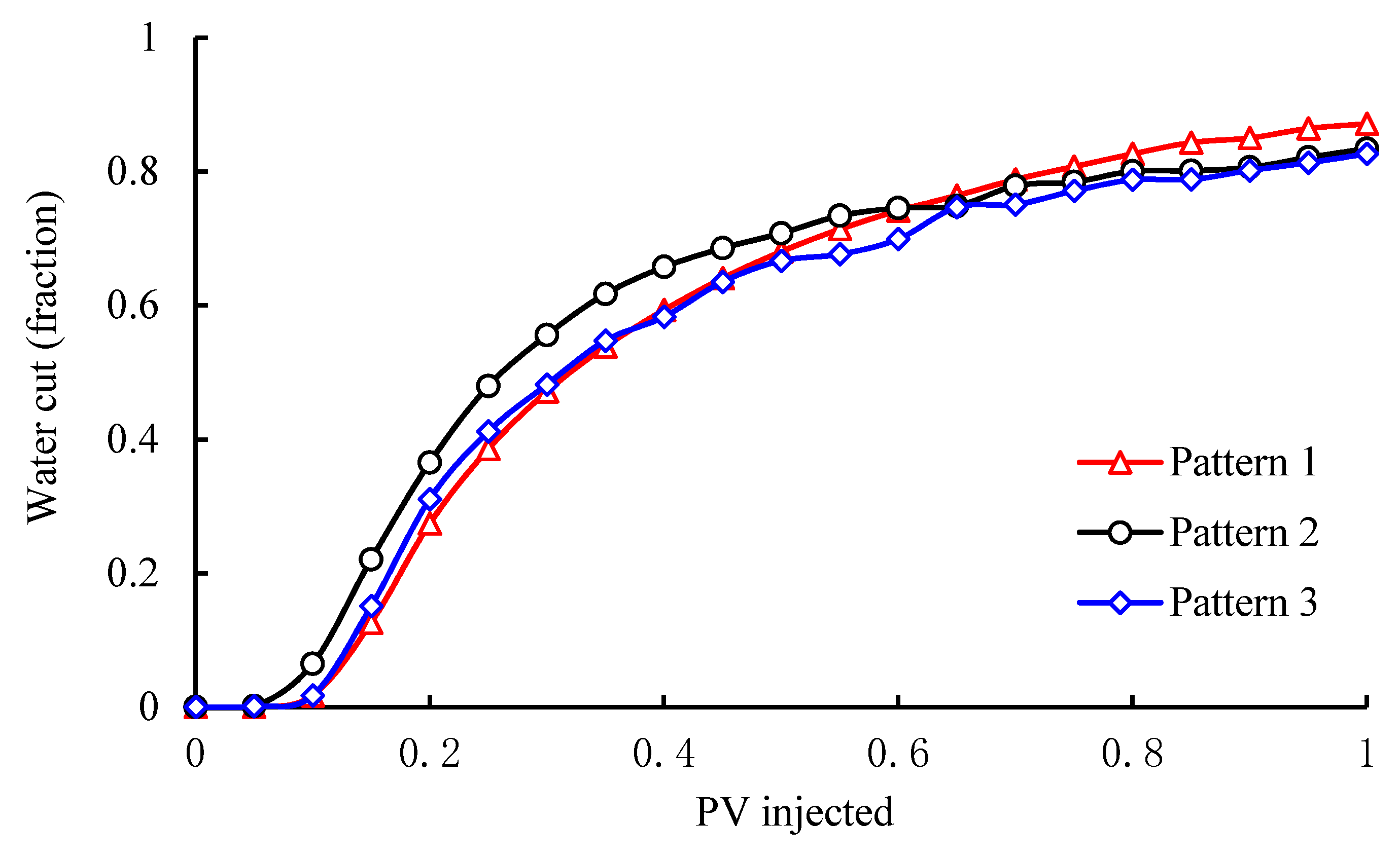
To further understand the influence of fracture length on the production performance of staged fracturing horizontal well, three patterns with different fracture length are considered, as shown in Figure 11. The fracture length of pattern 1 and pattern 3 equals 400 m and 200 m, respectively. The ratio of the middle regions’ and end regions’ fracture length is interpreted as the fracture length ratio for short. For pattern 2, the middle regions’ fracture length is limited to 400 m, and the fracture length ratio is 2.0. The other properties are identical to those of the basic scheme. Based on the proposed model, the production performance of the staged fracturing horizontal well under different patterns of fracture length are extensively investigated. The results are shown in Figure 12 and Figure 13.
From Figure 12 and Figure 13, it is referred that, the time needed for waterflood-front channeling into the horizontal wellbore becomes shorter while increasing the length of fractures nearby injectors, and a higher rise of water cut will be observed. Therefore, when conducting the optimal design of fracture properties, the length of fractures nearby the injectors should be shortened appropriately to avoid a too-early breakthrough of injected water.
5.2. Effect of Fracture Spacing
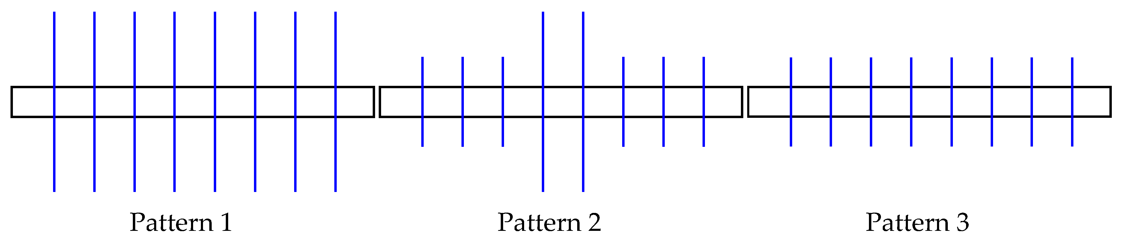
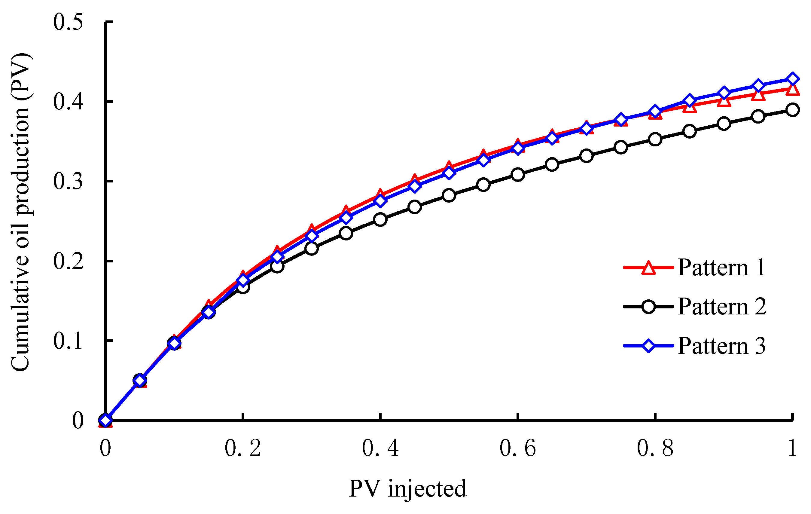
To understand the effect of fracture spacing on development effect of staged fracturing horizontal well, three patterns with different fracture spacing are considered, as shown in Figure 14. The fracture spacing between the first fracture and the 8th fracture is limited to 700 m, and the ratio of middle regions’ and end regions’ fracture spacing along the direction of the horizontal wellbore is defined as the fracture spacing ratio for short. In this study, the fracture spacing ratio of three different patterns is selected to be 1.0, 2.0 and 0.5, respectively. The other properties are identical to those of the basic scheme. Based on the proposed model, the production performance of the staged fracturing horizontal well under different patterns of fracture spacing are thoroughly investigated. The results are shown in Figure 15 and Figure 16.
As seen from Figure 15 and Figure 16, the shortest breakthrough time of injected water is obtained when fracture spacing in the midst is two times the fracture spacing in the end, and the minimum cumulative oil production is achieved. It can be explained as follows: in pattern 2, the fracture spacing nearby injectors is relatively small so that the injected water channels into the end regions’ fractures more quickly, which results in a larger rising rate of water cut and worse development effect. Therefore, it is of great importance to enlarge the end regions’ fracture spacing to delay the breakthrough time of injected water.
6. Case Study
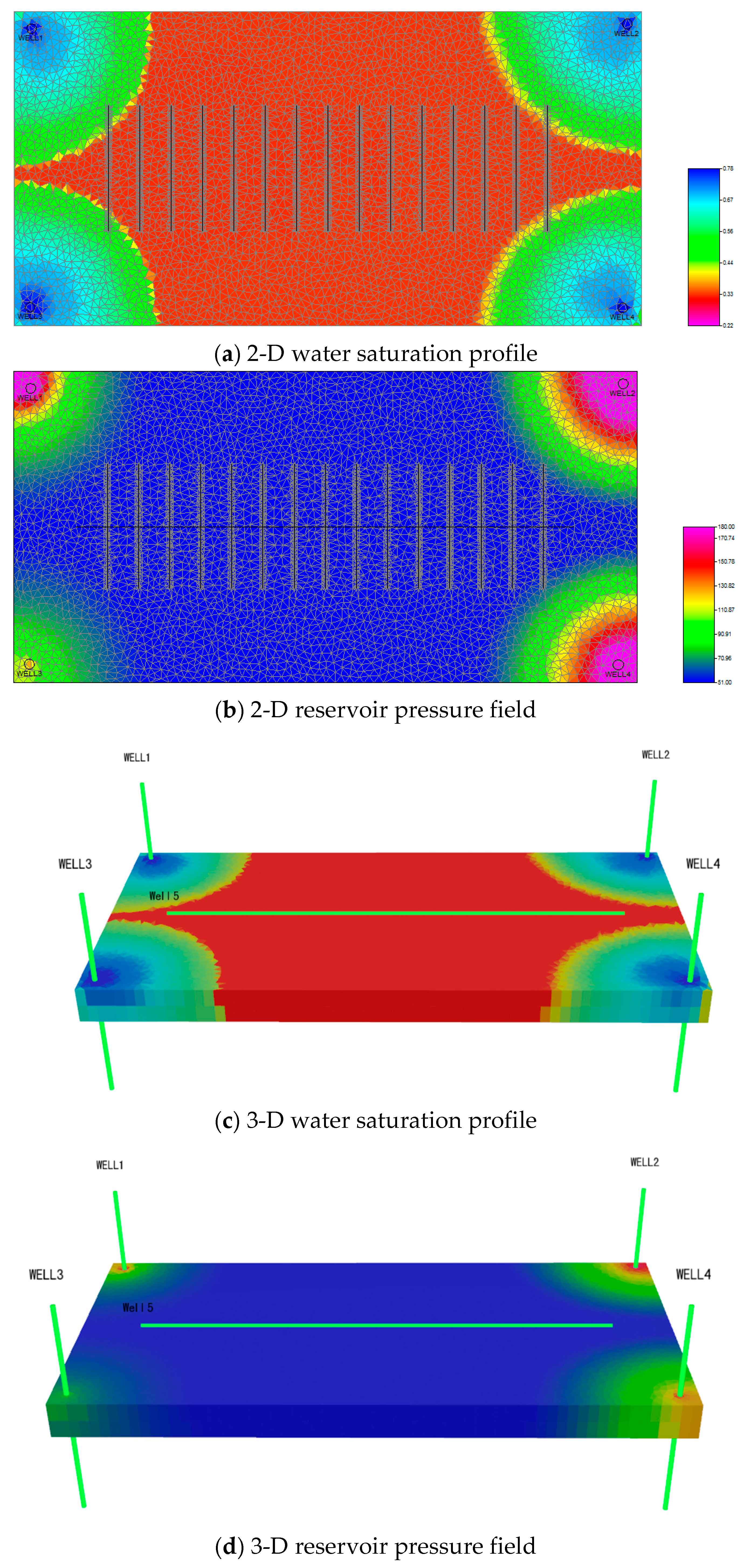
To further validate the practicability of the proposed model, a 3-D heterogeneous low permeability five-spot waterflood reservoir is established, as shown in Figure 17. The waterflood reservoir size is 2000 m × 1000 m × 24 m, which is vertically divided into 2 layers with a total of 30,149 grid cells. The traditional Kriging interpolation algorithm is then used to generate a heterogenous distribution of matrix permeability, as depicted in Figure 18. The rock and fluid properties for the staggered five-spot model are displayed in Table 2. The well pattern is one staged fracturing horizontal producer located in the center and four vertical injectors located in the corner faces. Water injection is achieved at a constant surface liquid rate of 60 m3/d, and oil production is triggered with a constant bottom hole pressure of 5.0 MPa. Based on our proposed model, the production performance of the 3-D heterogenous low-permeability waterflood reservoir is well documented.
Figure 19 illustrates the 2-D and 3-D water saturation profile and overall pressure field of low-permeability reservoir when a total of 0.085 PV water is injected. It shows that, due to the weak transport capacity of injected water in low-permeability reservoir, a relatively uniform waterfront advancing behavior is achieved before water breakthrough despite the heterogeneous permeability distribution, and majorities of remaining oil are still unexploited underground. This finding also agrees well with the actual production performance of low-permeability reservoirs commonly found in the Ordos basin, northwestern China, which provides powerful evidence for the applicability and reliability of our proposed model.
7. Conclusions
- (1)
- Using a discrete fracture model to reduce the dimension of the fracture network explicitly, the two-parameter model is used to represent the nonlinear flow behavior of multiphase fluid in porous media, and the equivalent percolation model of pipe flow is selected to calculate the wellbore pressure drop in a horizontal wellbore. A novel hybrid mathematical model for nonlinear two-phase flow in a fractured low-permeability waterflood reservoir is developed by combining the governing equations satisfied by the matrix, fracture and horizontal wellbore, respectively. By combing the MFD method and FV method, the numerical discretization of the hybrid model is derived and validated using a synthetic staggered five-spot flood system. The effect of fracture properties on nonlinear flow behaviors in fractured low-permeability reservoir are ultimately investigated.
- (2)
- The results show that with an increase of fracture length near injectors, injected water will cross into the horizontal wellbore more easily, resulting in a faster increase of water cut, and a worse development effect. The effect of shortening fracture spacing is consistent with that of increasing fracture length. When performing the optimization design of fracture parameters, it is necessary to shorten the length of fractures nearby injectors and enlarge the fracture spacing of end regions to avoid too early a breakthrough of injected water. Successful practice in modeling the complex waterflood behaviors for a 3-D heterogeneous reservoir provides powerful evidence for the practicability and reliability of our model.
Author Contributions
Conceptualization, D.W. and J.S.; methodology, D.W.; software, H.P.; validation, J.S., H.P. and Y.L.; formal analysis, D.W.; investigation, D.W.; resources, Y.L.; data curation, J.S.; writing—original draft preparation, D.W.; writing—review and editing, Y.L.; visualization, H.P.; supervision, Y.L.; project administration, D.W.; funding acquisition, D.W.
Funding
This research was funded by the National Natural Science Foundation of China (Grant No. 41806070 and 51874346), the PetroChina Innovation Foundation (Grant No. 2018D-5007-0201), the funding provided by the China Postdoctoral Science Foundation (Grant No. 2018M641069 and No. and 2019T120022), the Opening Fund of Key Laboratory of Unconventional Oil & Gas Development (China University of Petroleum (East China)), Ministry of Education, and the Fundamental Research Funds for the Central Universities.
Acknowledgments
The authors sincerely acknowledge the Research Institute of Petroleum Exploration and Development, PetroChina for permission to publish this paper. We are also grateful to all the anonymous reviewers for their constructive comments.
Conflicts of Interest
The authors declare no conflict of interest.
References
- Li, G.; Sheng, M.; Tian, S.; Huang, Z.; Li, Y.; Yuan, X. Multistage hydraulic jet acid fracturing technique for horizontal wells. Pet. Explor. Dev. 2012, 39, 100–104. [Google Scholar] [CrossRef]
- Liu, R.; Li, B.; Jiang, Y.; Yu, L. A numerical approach for assessing effects of shear on equivalent permeability and nonlinear flow characteristics of 2-D fracture networks. Adv. Water Resour. 2018, 111, 289–300. [Google Scholar] [CrossRef]
- Deng, Y.E.; Liu, C.Q. Mathematical model of nonlinear flow in low permeability porous media and its application. Acta Pet. Sin. 2001, 22, 72–77. [Google Scholar]
- Li, S.Q.; Cheng, L.S.; Li, X.S.; Hao, F. Nonlinear seepage flow models of ultra-low permeability reservoirs. Pet. Explor. Dev. 2008, 35, 606–612. [Google Scholar] [CrossRef]
- Yu, R.; Bian, Y.; Li, Y.; Zhang, X.; Yan, J.; Wang, H.; Wang, K. Non-Darcy flow numerical simulation of XPL low permeability reservoir. J. Pet. Sci. Eng. 2012, 92–93, 40–47. [Google Scholar]
- Shu, W.B.; Xu, H.H.; Wan, J.Y. Numerical research on dynamic effect of capillary pressure in low permeability reservoirs. Chin. J. Hydrodyn. 2014, 29, 189–196. [Google Scholar]
- Liu, W.; Yao, J.; Chen, Z.; Zhu, W. An exact analytical solution of moving boundary problem of radial fluid flow in an infinite low-permeability reservoir with threshold pressure gradient. J. Pet. Sci. Eng. 2019, 175, 9–21. [Google Scholar] [CrossRef]
- Shahraeeni, E.; Moortgat, J.; Firoozabadi, A. High-resolution finite element methods for 3D simulation of compositionally triggered instabilities in porous media. Comput. Geosci. 2015, 19, 899–920. [Google Scholar] [CrossRef]
- Cordero, J.A.R.; Sanchez, E.C.M.; Roehl, D.; Rueda, J.; Mejia, E. Integrated discrete fracture and dual porosity—Dual permeability models for fluid flow in deformable fractured media. J. Pet. Sci. Eng. 2019, 175, 644–653. [Google Scholar] [CrossRef]
- Abbasi, M.; Madani, M.; Sharifi, M.; Kazemi, A. Fluid flow in fractured reservoirs: Exact analytical solution for transient dual porosity model with variable rock matrix block size. J. Pet. Sci. Eng. 2018, 164, 571–583. [Google Scholar] [CrossRef]
- Noorishad, J.; Mehran, M. An upstream finite element method for solution of transient transport equation in fractured porous media. Water Resour. Res. 1982, 18, 588–596. [Google Scholar] [CrossRef] [Green Version]
- Karimi-Fard, M.; Firoozabadi, A. Numerical simulation of water injection in fractured media using discrete-fracture model and the Galerkin method. SPE Reserv. Eval. Eng. 2003, 6, 117–126. [Google Scholar] [CrossRef]
- Hoteit, H.; Firoozabadi, A. An efficient numerical model for incompressible two-phase flow in fractured media. Adv. Water Resour. 2008, 31, 891–905. [Google Scholar] [CrossRef]
- Hauge, V.L.; Aarnes, J.E. Modeling of two-phase flow in fractured porous media on unstructured non-uniformly coarsened grids. Transp. Porous Media 2009, 77, 373–398. [Google Scholar] [CrossRef]
- Zhang, N.; Yao, J.; Huang, Z.; Wang, Y. Accurate multiscale finite element method for numerical simulation of two-phase flow in fractured media using discrete-fracture model. J. Comput. Phys. 2013, 242, 420–438. [Google Scholar] [CrossRef]
- Zhou, F.Q.; Shi, A.F.; Wang, X.H. An efficient finite difference model for multiphase flow in fractured reservoirs. Pet. Explor. Dev. 2014, 41, 262–266. [Google Scholar] [CrossRef]
- Khoei, A.R.; Hosseini, N.; Mohammadnejad, T. Numerical modeling of two-phase fluid flow in deformable fractured porous media using the extended finite element method and an equivalent continuum model. Adv. Water Resour. 2016, 94, 510–528. [Google Scholar] [CrossRef]
- Hosseinimehr, M.; Cusini, M.; Vuik, C.; Hajibeygi, H. Algebraic dynamic multilevel method for embedded discrete fracture model (F-ADM). J. Comput. Phys. 2018, 373, 324–345. [Google Scholar] [CrossRef] [Green Version]
- Baca, R.G.; Arnett, R.C.; Langford, D.W. Modeling fluid flow in fractured-porous rock masses by finite element techniques. Int. J. Numer. Methods Fluids 1984, 4, 337–348. [Google Scholar] [CrossRef]
- Zidane, A.; Firoozabadi, A. An efficient numerical model for multicomponent compressible flow in fractured porous media. Adv. Water Resour. 2014, 74, 127–147. [Google Scholar] [CrossRef]
- Stefansson, I.; Berre, I.; Keilegavlen, E. Finite-volume discretizations for flow in fractured porous media. Transp. Porous Media 2018, 124, 439–462. [Google Scholar] [CrossRef]
- Jiang, L.; Moulton, J.D.; Svyatskiy, D. Analysis of stochastic mimetic finite difference methods and their applications in single-phase stochastic flows. Comput. Methods Appl. Mech. Eng. 2012, 217–220, 58–76. [Google Scholar] [CrossRef]
- Huang, Z.; Yan, X.; Yao, J. A two-phase flow simulation of discrete fractured media using mimetic finite difference method. Commun. Comput. Phys. 2014, 16, 799–816. [Google Scholar] [CrossRef]
- Yan, X.; Huang, Z.; Yao, J.; Li, Y.; Fan, D.; Sun, H.; Zhang, K. An efficient numerical hybrid model for multiphase flow in deformable fractured-shale reservoirs. SPE J. 2018, 23, 1412–1437. [Google Scholar] [CrossRef]
- Yan, X.; Huang, Z.; Yao, J.; Li, Y.; Fan, D. An efficient embedded discrete fracture model based on mimetic finite difference method. J. Pet. Sci. Eng. 2016, 145, 11–21. [Google Scholar] [CrossRef]
- Zhang, Q.; Huang, Z.; Yao, J.; Wang, Y.; Li, Y. Multiscale mimetic method for two-phase flow in fractured media using embedded discrete fracture model. Adv. Water Resour. 2017, 107, 180–190. [Google Scholar] [CrossRef]
- Jing, P.; Omar, A.H.; Mary, F.W. Data assimilation method for fractured reservoirs using mimetic finite differences and ensemble Kalman filter. Comput. Geosci. 2017, 21, 781–794. [Google Scholar]
- Gyrya, V.; Lipnikov, K. The arbitrary order mimetic finite difference method for a diffusion equation with a non-symmetric diffusion tensor. J Comput. Phys. 2017, 348, 549–566. [Google Scholar] [CrossRef]
- Dikken, B.J. Pressure drop in horizontal wells and its effect on their production performance. J. Pet. Technol. 1990, 42, 1426–1433. [Google Scholar] [CrossRef]
- Jansen, J.D. A semi-analytical model for calculating pressure drop along horizontal wells with stinger completions. SPE J. 2003, 8, 138–146. [Google Scholar] [CrossRef]
- Yao, S.; Zeng, F.; Liu, H.; Zhao, G. A semi-analytical model for multi-stage fractured horizontal wells. J. Hydrol. 2013, 507, 201–212. [Google Scholar] [CrossRef]
- Chen, Z.; Liao, X.; Zhao, X.; Zhu, L.; Liu, H. Performance of multiple fractured horizontal wells with consideration of pressure drop within wellbore. J. Pet. Sci. Eng. 2016, 146, 677–693. [Google Scholar] [CrossRef]
- Li, H.; Tan, Y.; Jiang, B.; Wang, Y.; Zhang, N. A semi-analytical model for predicting inflow profile of horizontal wells in bottom-water gas reservoir. J. Pet. Sci. Eng. 2018, 160, 351–362. [Google Scholar] [CrossRef]
- Vodorezov, D.D. Estimation of horizontal-well productivity loss caused by formation damage on the basis of numerical modeling and laboratory-test data. SPE J. 2019, 24, 44–59. [Google Scholar] [CrossRef]
- Wu, S.H.; Liu, X.E.; Guo, S.P. A simplified model of flow in horizontal wellbore. Pet. Explor. Dev. 1999, 26, 64–66. [Google Scholar]
- Birchenko, V.M.; Usnich, A.V.; Davies, D.R. Impact of frictional pressure losses along the completion on well performance. J. Pet. Sci. Eng. 2010, 73, 204–213. [Google Scholar] [CrossRef]
- Wang, Z.; Zhang, Q.; Zeng, Q.; Wei, J. A unified model of oil/water two-phase flow in the horizontal wellbore. SPE J. 2017, 22, 353–364. [Google Scholar] [CrossRef]
- Lipnikov, K.; Manzini, G.; Moulton, J.D.; Shashkov, M. The mimetic finite difference method for elliptic and parabolic problems with a staggered discretization of diffusion coefficient. J. Comput. Phys. 2016, 305, 111–126. [Google Scholar] [CrossRef] [Green Version]
Figure 1.
Schematic of grid analysis for mimetic finite difference method.

Figure 2.
Schematic of a typical fractured media (left); the unstructured grid (right).

Figure 3.
Sketch map of horizontal wellbore flow.

Figure 4.
Scheme of staggered five spot water-injection model.

Figure 5.
Delaunay triangulation of the water-injection model.

Figure 6.
Mass flux distribution of different lateral segments in horizontal well.

Figure 7.
Evolution of frictional pressure drop across the horizontal wellbore.

Figure 8.
Water saturation profiles at different injection pore volume multiples.

Figure 9.
Oil production performance of staged fractured horizontal well.

Figure 10.
Water cut variation of staged fractured horizontal well.

Figure 11.
Schematic of different fracture length patterns.

Figure 12.
Water cut variation under different fracture length patterns.

Figure 13.
Cumulative oil production variation under different fracture lengths.

Figure 14.
Schematic of different fracture spacing patterns.

Figure 15.
Water cut curve under different fracture spacing patterns.

Figure 16.
Cumulative oil production variation under different fracture spacings.

Figure 17.
Delaunay triangulation of the heterogeneous waterflood model.

Figure 18.
Heterogeneous distribution of matrix permeability in five-spot system.

Figure 19.
Water saturation and reservoir pressure profile at 0.085PV water injected.


Table 1.
Rock and fluid properties for the staggered five spot water-injection model.
| Parameter | Value | Parameter | Value |
|---|---|---|---|
| reservoir dimensions | 1000 m × 800 m | water viscosity | 1 mPa∙s |
| matrix porosity | 0.1 | oil viscosity | 5 mPa∙s |
| matrix permeability | 1 × 10⁻³ μm2 | water density | 1000 kg/m3 |
| fracture length | 400 m | oil density | 800 kg/m3 |
| fracture spacing | 100 m | inject rate | 0.05 PV/day |
| fracture aperture | 1 mm | production rate | 0.05 PV/day |
| fracture permeability | 8.33 × 104 μm2 | irreducible water saturation | 0.3 |
| length of lateral segment | 900 m | residual oil saturation | 0.1 |
Table 2.
Rock and fluid properties for the 3-D heterogeneous waterflood reservoir.
| Parameter | Value | Parameter | Value |
|---|---|---|---|
| matrix porosity | 0.1 | water viscosity | 1.0 mPa∙s |
| matrix permeability | 0.1~2.0 mD | oil viscosity | 5.0 mPa∙s |
| fracture conductivity | 5.0 | water density | 1000 kg/m3 |
| fracture length | 400 m | oil density | 750 kg/m3 |
| fracture spacing | 100 m | inject rate | 60 m3/d |
| length of lateral segment | 1600 m | BHP pressure | 5.0 MPa |
| initial reservoir pressure | 20 MPa | irreducible water saturation | 0.35 |
| bubble point pressure | 28 MPa | residual oil saturation | 0.22 |
© 2019 by the authors. Licensee MDPI, Basel, Switzerland. This article is an open access article distributed under the terms and conditions of the Creative Commons Attribution (CC BY) license (http://creativecommons.org/licenses/by/4.0/).
Share and Cite
MDPI and ACS Style
Wang, D.; Sun, J.; Li, Y.; Peng, H. An Efficient Hybrid Model for Nonlinear Two-Phase Flow in Fractured Low-Permeability Reservoir. Energies 2019, 12, 2850. https://doi.org/10.3390/en12152850
AMA Style
Wang D, Sun J, Li Y, Peng H. An Efficient Hybrid Model for Nonlinear Two-Phase Flow in Fractured Low-Permeability Reservoir. Energies. 2019; 12(15):2850. https://doi.org/10.3390/en12152850
Chicago/Turabian StyleWang, Daigang, Jingjing Sun, Yong Li, and Hui Peng. 2019. "An Efficient Hybrid Model for Nonlinear Two-Phase Flow in Fractured Low-Permeability Reservoir" Energies 12, no. 15: 2850. https://doi.org/10.3390/en12152850
Note that from the first issue of 2016, this journal uses article numbers instead of page numbers. See further details here.