Article

Enhancing the Heat Transfer in an Active Barocaloric Cooling System Using Ethylene-Glycol Based Nanofluids as Secondary Medium

1
Department of Industrial Engineering, University of Salerno, Via Giovanni Paolo II 132, 84084 Fisciano (SA), Italy
2
Department of Industrial Engineering, University of Naples Federico II, P.le Tecchio 80, 80125 Napoli, Italy
*
Author to whom correspondence should be addressed.
Energies 2019, 12(15), 2902; https://doi.org/10.3390/en12152902
Submission received: 16 July 2019 / Revised: 23 July 2019 / Accepted: 26 July 2019 / Published: 28 July 2019
(This article belongs to the Special Issue Refrigeration Systems and Applications 2019)

Abstract

:
Barocaloric cooling is classified as environmentally friendly because of the employment of solid-state materials as refrigerants. The reference and well-established processes are based on the active barocaloric regenerative refrigeration cycle, where the solid-state material acts both as refrigerant and regenerator; an auxiliary fluid (generally water of water/glycol mixtures) is used to transfer the heat fluxes with the final purpose of subtracting heat from the cold heat exchanger coupled with the cold cell. In this paper, we numerically investigate the effect on heat transfer of working with nanofluids as auxiliary fluids in an active barocaloric refrigerator operating with a vulcanizing rubber. The results reveal that, as a general trend, adding 10% of copper nanoparticles in the water/ethylene-glycol mixture carries to +30% as medium heat transfer enhancement.

1. Introduction

The 21st century is characterized by a strong increase in energy demand. The World Bank Open Data assert that the worldwide per capita energy consumption rose from 1400 kWh in 1975 to 3200 kWh in our current days [1]. This hunger for energy impacts all sectors, among the most crucial of which are refrigeration and air-conditioning fields, to which more than 20% of the total world energy consumption is attributed. The need to propose alternative solutions to the now well-established cooling techniques has been a hot topic since the 1990s, alongside the first measures adopted by the Montreal Protocol [2], the Kyoto Protocol [3], and the following amendments [4], which had the aim of reducing environmental impact due to the refrigerant fluids used in vapor compression. The initial immediate measures adopted by the scientific community were devoted to replacing the most damaging fluids with substitute refrigerants [5,6,7]. Subsequently, there was a push to extend the research to alternative techniques that could completely change the ways of refrigerating and air conditioning [8,9,10,11]. One possible solution for supplying compensation for the use of vapor compression is represented by the Not-In-Kind cooling technologies [12] with specific emphasis on caloric refrigeration [13,14].
Caloric refrigeration embraces all the cooling techniques and was founded on a physical phenomenon according to which, due to an adiabatic change in the intensity of an external field, a variation of temperature (∆Tad) is detected in a solid-state material to which the field is applied [15,16]. The specificity of the field particularizes such effects classified as caloric; a magnetic field generates a magnetocaloric effect (MCE) [17,18,19], electric fields are associated with electrocaloric effects (ECE) [20,21,22], and mechanical fields provoke elastocaloric (eCE) [23] or barocaloric effects (BCE) [24], respectively, as consequences of stretching or of hydrostatic pressure application.
Caloric cooling is classified as environmentally friendly because it employs solid-state materials as refrigerants that do not directly impact global warming since they do not disperse in the atmosphere, as confirmed by a certain number of investigations [25,26,27,28] that asserted the eco-friendliness of all the techniques belonging to magneto- [29,30], electro-[31,32], elasto- [33,34], and baro-caloric [35] cooling.
The reference and well-established systems for caloric cooling are based on the active caloric regenerative refrigeration (ACR) cycle, a thermodynamic Brayton-based cycle in which the caloric solid-state material acts as both the refrigerant and the regenerator, thus recovering heat fluxes through the help of an auxiliary fluid that vehiculates them with the final purpose of subtracting heat from the cold heat exchanger (and therefore the cold environment) [36]. To improve the efficiency of a caloric cooler, the ACR system works with the optimal operative parameters (such as the geometry of the regenerator, the fluid velocity, and the frequency of the cycle) [37,38,39] but the bottleneck is employing materials due of high caloric effect in the temperature range toward the application is devoted to [40]. A very wide “chapter” is currently open in the research panorama regarding the efforts to realize suitable caloric effect materials. A huge number of studies have been conducted over the last decades, and several promising materials have been identified for each specific caloric technique [41,42,43].
Magnetocaloric is the most mature solid-state cooling technique [44,45], as it was the first to be investigated; however, there are still inherent limitations and holdups in creating high-intensity magnetic fields by permanent magnet application [46,47]. More recently, electrocaloric and elastocaloric techniques have gained interest in the scientific community—certain objectives are being reached, and many prototypes have been presented and patented [48,49,50]. The barocaloric technique is the more embryonic caloric cooling technique. Initial studies have already identified promising barocaloric materials due to enhanced BCE that make it suitable for refrigeration and heat pump applications [51,52]. Vulcanizing natural rubbers and elastomers materials based on polydimethylsiloxane that exhibit giant barocaloric effects have gained certain interest [53,54].
On the one hand, important steps have been taken in researching caloric materials. However, on the other, much less attention has been paid to the secondary fluid of the active caloric system. Until now, the most common auxiliary fluids were water or water-glycol mixtures, according to the operating temperature ranges of the systems (above or below the zero Celsius point). Since the auxiliary fluid is responsible for the heat vehiculation in the regenerator from one side to another, optimizing solutions should be proposed for enhancing the heat transfer between the solid-state refrigerant and the fluid itself. One of these is constituted by nanofluids.
Nanofluids are classified as a new kind of heat transfer fluid; they are formed by common base fluids in which solid-state nanoparticles are dispersed due to high thermal conductivity. The nanoparticles, as the name suggests, present nanometric dimensions (< 100 nm) and could have metallic or non-metallic natures. The resulting fluid is a stable mixture of a base fluid with nanoparticles—called nanofluid—due to the enhanced thermal conductivity with respect to the starting base fluid [55]. In 1995, Choi [56] presented the scientific community with the concept of nanofluids, and the discovery was revolutionary. Over the years, nanofluids attracted many scientists from all over the world, who started to test them in wide-ranging applications [57,58,59,60,61,62,63]. Therefore, the use of nanofluids seems to be very promising in enhancing the thermal conductivity of a base fluid, but attention must be paid to the synthesis and the characterizations of them. Depending on the dimensions and the nature of the base fluid and the nanoparticles, the most appropriate methods for nanofluids synthesis must be chosen to avoid undesired effects, such as agglomeration, which takes place during the process of drying, storage, and transportation of nanoparticles. Agglomeration causes settlement and clogging of the channels, and the thermal conductivity of the nanofluids is consequently decreased. In some cases, to avoid potential agglomeration, specific processes of synthesis of the nanofluids could require high costs, and this could represent a drawback in their employment [64].
In regards to solid-state refrigeration, just two methods have been studied for the application of nanofluids in the caloric systems, and both were focused on magnetocaloric refrigeration [65,66]. Working with nanofluids in other caloric-effects-based cooling systems is still an unexplored field. In this paper, we introduce a numerical study conducted on an active barocaloric refrigerator operating with a vulcanizing rubber, which employed glycol-based nanofluids as auxiliary fluid. The tool employed for the investigation was a two-dimensional model of a parallel-plates active caloric regenerator, which was already validated experimentally in our previous investigations [16,67,68]. The analysis is focused mainly on the heat transfer performances of the regenerator.

2. Thermodynamic Cycle and the Tool of the Investigation

2.1. ABR Cycle: The Thermodynamic Cycle for Barocaloric Cooling

The active caloric regenerative refrigeration cycle applied to barocaloric cooling is defined as the ABR cycle (active barocaloric regenerative refrigeration cycle). As is visible in Figure 1, the ABR cycle is composed of four processes that are repeated cyclically in a refrigeration system:
  • Adiabatic compression;
  • Heat vehiculation from Cold Heat EXchanger (CHEX) to Hot Heat EXchanger (HHEX);
  • Adiabatic decompression;
  • Heat vehiculation from HHEX to CHEX.
The cycle is experimented upon by a barocaloric system formed by a regenerator containing the barocaloric refrigerant and crossed by a thermo-vectoral fluid called heat transfer fluid (HTF), which connects CHEX with HHEX. A pressure cell is used to change the operation pressure.
In the first step (A), the barocaloric regenerator is adiabatically compressed by means of the pressure cell; this causes the barocaloric effect to manifest with a rising temperature in the barocaloric material. After the compression, while keeping the pressure at maximum value, the HTF flows from the cold to the hot heat exchanger (B), thus the regenerator cools down, and the heat transferred to the fluid is released in the HHEX. When the fluid stops blowing, the adiabatic decompression begins (C), and pressure progressively decreases until reaching the minimum value. As a result, the regenerator cools further due to BCE. In the last step (D), the fluid crosses from HHEX to CHEX in the barocaloric regenerator, releasing heat to the latter and thus realizing the desired effect with the heat removed from CHEX.

2.2. Numerical Model

A two-dimensional (2-D) model of the parallel-plate matrix of the barocaloric material with stacking channels for HTF flow was employed to perform the investigation introduced in this paper.
Figure 2 shows the geometry of the model. The HTF flows along the x-axis in both directions. On the left side, by means of a first-type boundary condition, the presence of CHEX (with TC as the set point temperature) is modeled; the same is done on the right side, where TH is the first-type condition associated with HHEX.
The mathematical system that stems from forcing the ABR cycle on the geometry is composed of the following equations:
{ u x + v y = 0 u t + u u x + v u y = 1 ρ nf p x + υ ( 2 u x 2 + 2 u y 2 )   v t + u v x + v v y = 1 ρ nf p y + υ ( 2 v x 2 + 2 v y 2 ) T nf t + u T nf x + v T nf y = k nf ρ nf C nf ( 2 T nf x 2 + 2 T nf y 2 ) T s t = k s ρ s C s ( 2 T s x 2 + 2 T s y 2 ) ,
{ ρ nf C nf T nf t = k nf ( 2 T nf x 2 + 2 T nf y 2 ) ρ s C s T s t = k s ( 2 T s x 2 + 2 T s y 2 ) + Q ,
Q = Q ( p , T S ) = ρ s   C s Δ T ad ( p   , T s ) τ ,
The equations system (1), which defines the continuity of mass equation, the momentum equations of fluid (Navier-Stokes), and the fluid and the solid energy equations, is imposed during the fluid flow processes (steps B and D of the ABR, as shown in Figure 1). Laminar flow and incompressible fluid are assumed.
The equations system (2) acts during the phases of adiabatic compression and decompression. Because the fluid is not moving in these steps, it is composed only by the fluid and the solid energy equations. In the solid energy equation, the temperature change due to barocaloric effect is included by means of Q term, whose expression is explicated in Equation (3). Equation (3) practically converts the adiabatic temperature change due to BCE in a power density. The term depends on the working temperature of the barocaloric material and the applied pressure to the system. The related mathematical function for Q is evaluated through mathematical finder software following the elaboration and the manipulation of experimental data of specific heat and ∆Tad(p, Ts), according to scientific literature. A complete description of all the steps we followed in the Q-terms building is reported in Aprea et al. [16]. Next to the construction and the manner of including Q in the field increasing/decreasing processes of the 2-D model, we detail how we accounted for the phenomenon of the thermal hysteresis that could become relevant for first order transition materials.
The model is solved through the finite element method (FEM). The ABR cycle is repeated cyclically many times until detecting that the regenerator has reached the steady-state condition. The latter must satisfy the cyclicality criterion in every point of the ABR regenerator:
δ = m a x { T ( x , y , 0 + q θ ) T ( x , y , 4 τ + q θ ) } < ε ¯ ,
The main peculiarity of this model is the extreme flexibility in making the caloric regenerator work with every caloric effect material (magneto-, electro-, elasto-, baro-), regardless of the specificity of the nature of the caloric effect exhibited. This extreme ductility constitutes a strongpoint of the tool, and it allows for the possibility of experimentally validating the model with just one of the four caloric effect-based prototypes. To this purpose, the model was introduced in our previous investigations [16,67] and validated with a prototype of a magnetocaloric cooler developed at University of Salerno. The validation, carried out both at zero load and with refrigerant load, showed fairly good agreement with experimental data [16,67,69].

3. Materials Employed in the Investigation

3.1. The Solid-State Barocaloric Refrigerant

The choice of the solid-state refrigerant to be employed in the active barocaloric system was done according to the requirements underlined by Aprea et al. [16] that a material must satisfy to be considered suitable for the specific caloric application.
We ultimately chose a barocaloric refrigerant with natural materials and elastomeric properties: acetoxy silicone rubber (ASR) [70]. Polydimethylsiloxane, additive, preserving agents and fillers are the components forming ASR, the latter exhibits a super-giant barocaloric effect with a peak of adiabatic change of temperature falling in correspondence of the crystalline–amorphous transitions with the consequence of polymer chains rearrangements. The adiabatic temperature change detected in acetoxy silicone rubber for decompression (∆p = 0.390 GPa) is shown in Figure 3.
The main thermodynamical and barocaloric features of ASR are reported in Table 1. A 41.1 K peak of adiabatic change of temperature occurs at 298 K. The latter data confers to ASR a relevant barocaloric effect in the temperature range where cooling and freezing applications are devoted to.
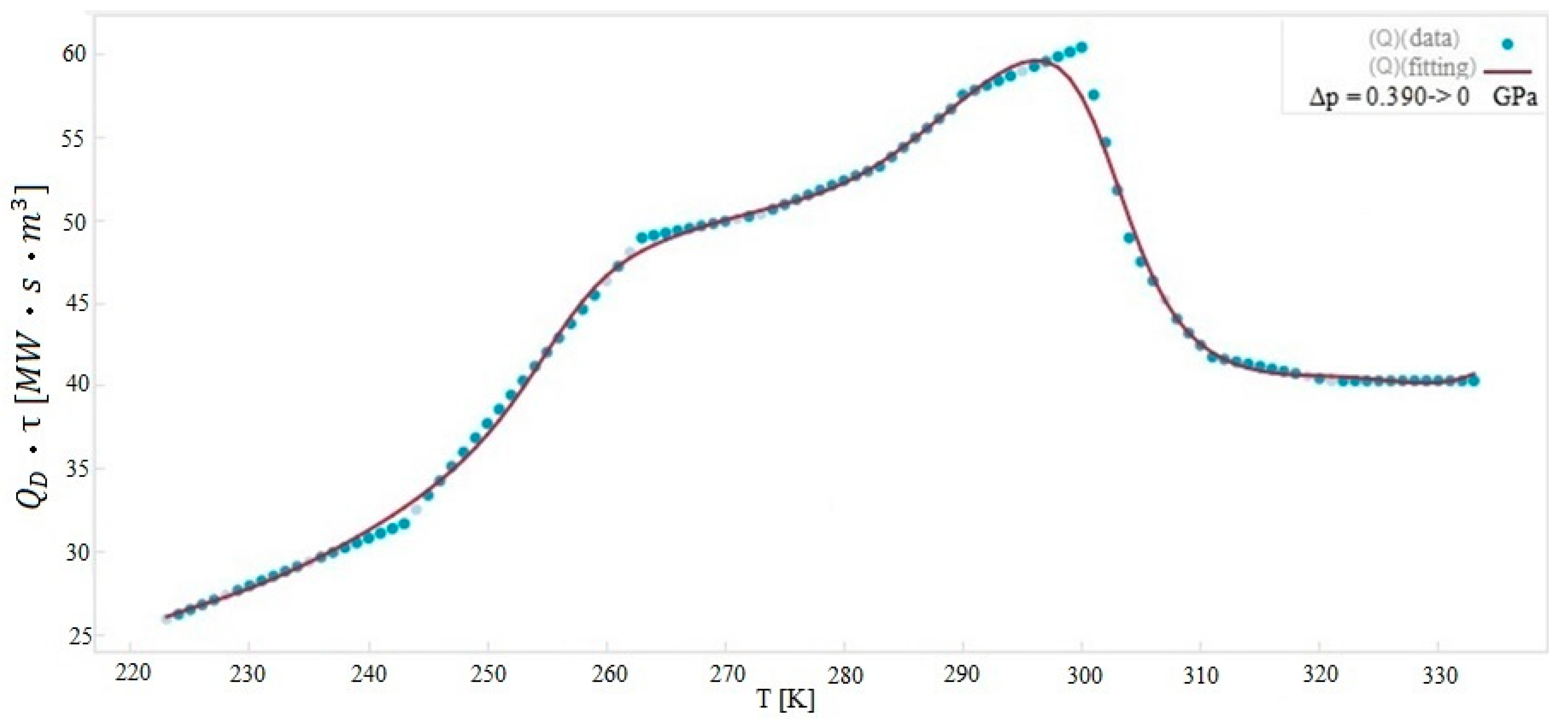
Following the methodology introduced in Section 2.2 about Q modeling, we built the mathematical expressions of Q terms for acetoxy silicone rubber. As an example, we report in Figure 4 the fitting of the Q term for the ASR representative of the adiabatic decompression process from 0.390 GPa to 0 GPa.
The resulting mathematical expression is:
Q D · τ = 10 6 ( 1.33 T + 0.000211 T 2 sin ( 4.33 + sin ( 0.0636 T ) ) s i n ( 4.12 + sin ( 0.0726 T ) ) 165 0.00216 T 2 ) ,

3.2. Nanofluids as Heat Transfer Termvectorial Fluid

The role played by the secondary fluid is crucial for the heat vehiculation between the cold and the hot heat exchanger. Therefore, the heat transfer processes between the solid (parallel plates of barocaloric materials) and the fluid (auxiliary fluid) should be as efficient as possible so to allow the regenerator to work at a higher frequency in the ABR cycle. The optimization of the solid–fluid heat transfer process was not investigated deeply. Therefore, we proposed nanofluids as the solution to improve heat exchange, replacing the ordinary, common base fluids used until now (water or water-glycol mixtures).
The temperature range used in this investigation was one typical of refrigeration and freezing purposes; therefore, the starting base fluid was a 50% water − 50% ethylene glycol (EG) mixture, where the freezing point was 236 K. To improve the thermal conductivity of such an auxiliary fluid, Cu nanoparticles were dispersed. Thus, we chose to operate with metallic nanofluids because of the non-interaction of the metallic nature with the field generation for detecting the barocaloric effect (whose nature is mechanical).
As a result, the heat transfer fluids considered in the investigation and presented in this paper were Cu + 50% water − 50% EG nanofluids with variable concentrations of nanoparticles of nanometric dimensions (1÷10 nm). The thermophysical characteristics of the Cu nanoparticles are listed in Table 2.
The considered thermophysical properties of the base fluid (50% water − 50% EG) were provided by the American Society of Heating, Refrigerating and Air-Conditioning Engineers (A. S. H. R. A. E.) as table functions of the temperature [71]. We elaborated such data in the resulting mathematical expression as follows:
ρ bf = 1777 0.3482 T ,
C bf = 2150 + 3.866 T ,
k bf = 0.141 + 0.000769 T ,
μ bf = 0.6474 229.5 T 0.006321 ,
The thermophysical properties of the nanofluids were evaluated through the following mathematical correlations (available in open scientific literature) [72,73,74]:
ρ nf = ( 1 φ )   ρ bf + φ   ρ np ,
ρ nf C p , nf = ( 1 φ ) ( ρ C p ) bf + φ   ( ρ C p ) np ,
μ nf = 1 ( 1 φ ) 2.5 μ bf ,
k nf = k np + ( n 1 )   k bf ( n 1 )   φ   ( k bf k np ) k np + ( n 1 )   k bf +   φ   ( k bf k np ) ,
where, supposing spherical nanoparticles, the empirical shape factor (n) is equal to 3.

4. Working Conditions of the Investigation

The model employed in this paper could reproduce the thermal-fluid dynamic behavior of an active caloric system for cooling purposes. In the investigation, the model was used to simulate the behavior of an ABR system working in refrigeration and freezing mode. The set-point temperatures of the cold and the hot heat exchangers were fixed, respectively, at TC = 255 K and TH = 290 K, and the frequency of the ABR cycle was 1.25 Hz. The system was tested at variable HTF velocities in the range 0.04 ÷ 0.2 m/s. The Cu + 50% water − 50% EG nanofluid volume fraction also varied from 0% to 10%.

5. Results and Discussion

This paper mainly focused on the heat transfer between the solid and the fluid and on the investigation of possible solutions for its enhancement. Therefore, to this aim, we focus on one of the channels in which the HTF flows and there are two stacking parallel-plates of barocaloric material.
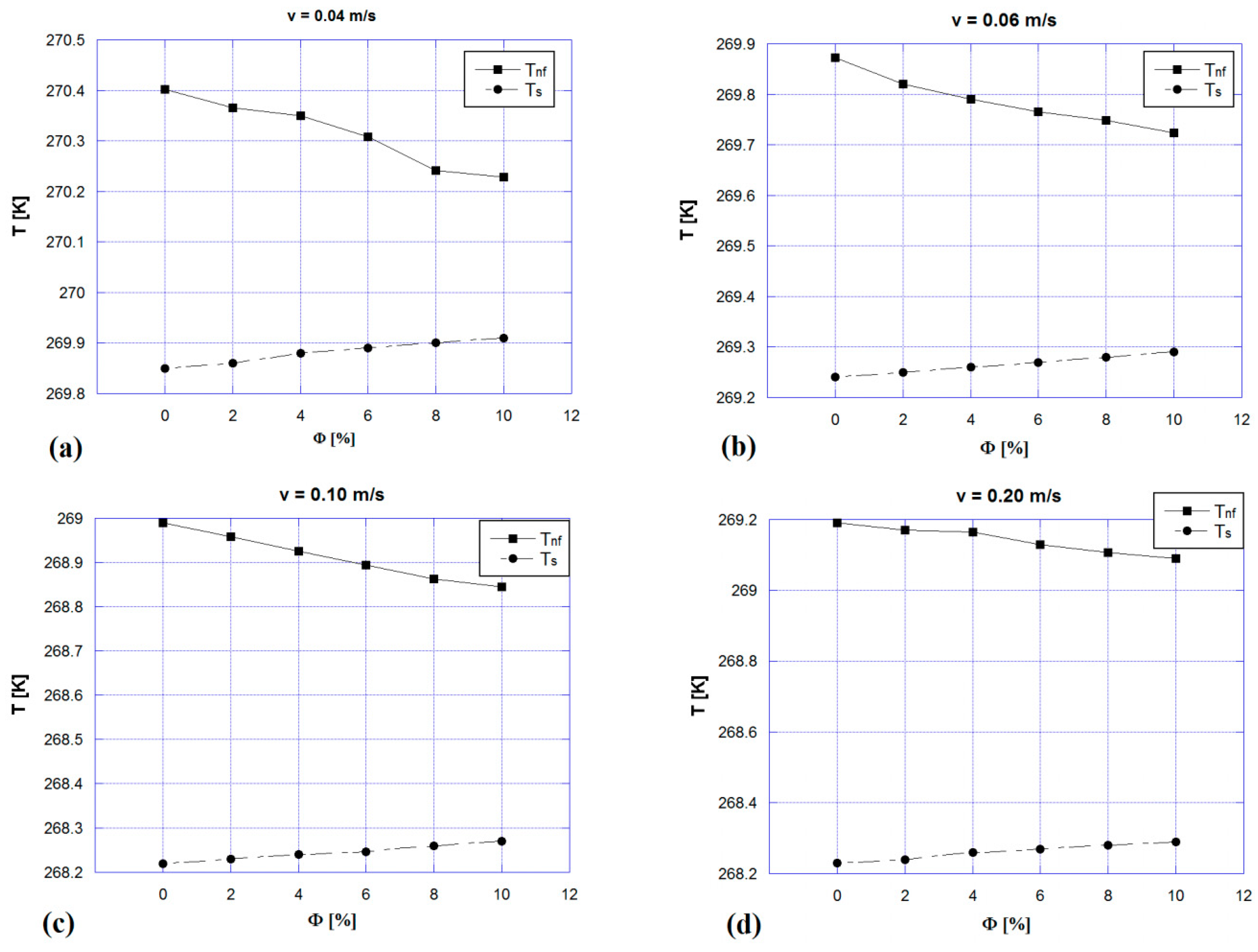
Figure 5 reports the mean temperature values of the boundaries of the channel (made of barocaloric material) and of the nanofluid flowing during the fourth step of the ABR cycle as a function of volume fraction and for a number of nanofluid velocities: (a) 0.04 m/s; (b) 0.06 m/s; (c) 0.10 m/s; (d) 0.20 m/s. From the figures, one can appreciate that the temperature difference between solid and nanofluid was reduced as nanoparticle volume fraction increased. This indicated that the heat exchange was improved following augmentation of φ . Furthermore, one can notice that increased fluid velocity caused a better exchange with the solid, and as a consequence, the fluid had a lower mean temperature, whereas the solid had a higher one. Figure 5c represents an exception, because the fluid temperature was slightly lower than the fluid with a velocity of 0.20 m/s (Figure 5d).
The most important indicator to evaluate the heat transfer performances between the solid and the fluid is represented by the convective heat transfer coefficient, defined as the proportionality coefficient between the convective heat flux at the solid-state boundaries of the channel and the temperature drop between solid and fluid. Therefore, in our investigation, we evaluated it as:
h = q ˙ c Δ T
The local convective heat flux was evaluated as:
q ˙ c ( x , t ) = k nf T nf y ,
whereas the temperature difference was evaluated as:
Δ T = T nf T s ,
where both the partial derivative in Equation (15) and the temperature difference in Equation (16) were evaluated at the boundary between the fluid and the solid interface. To obtain the mean value of the heat transfer coefficient, both the local heat flux and the temperature difference were evaluated as mean values along the channel wall with respect to the fluid flow time.
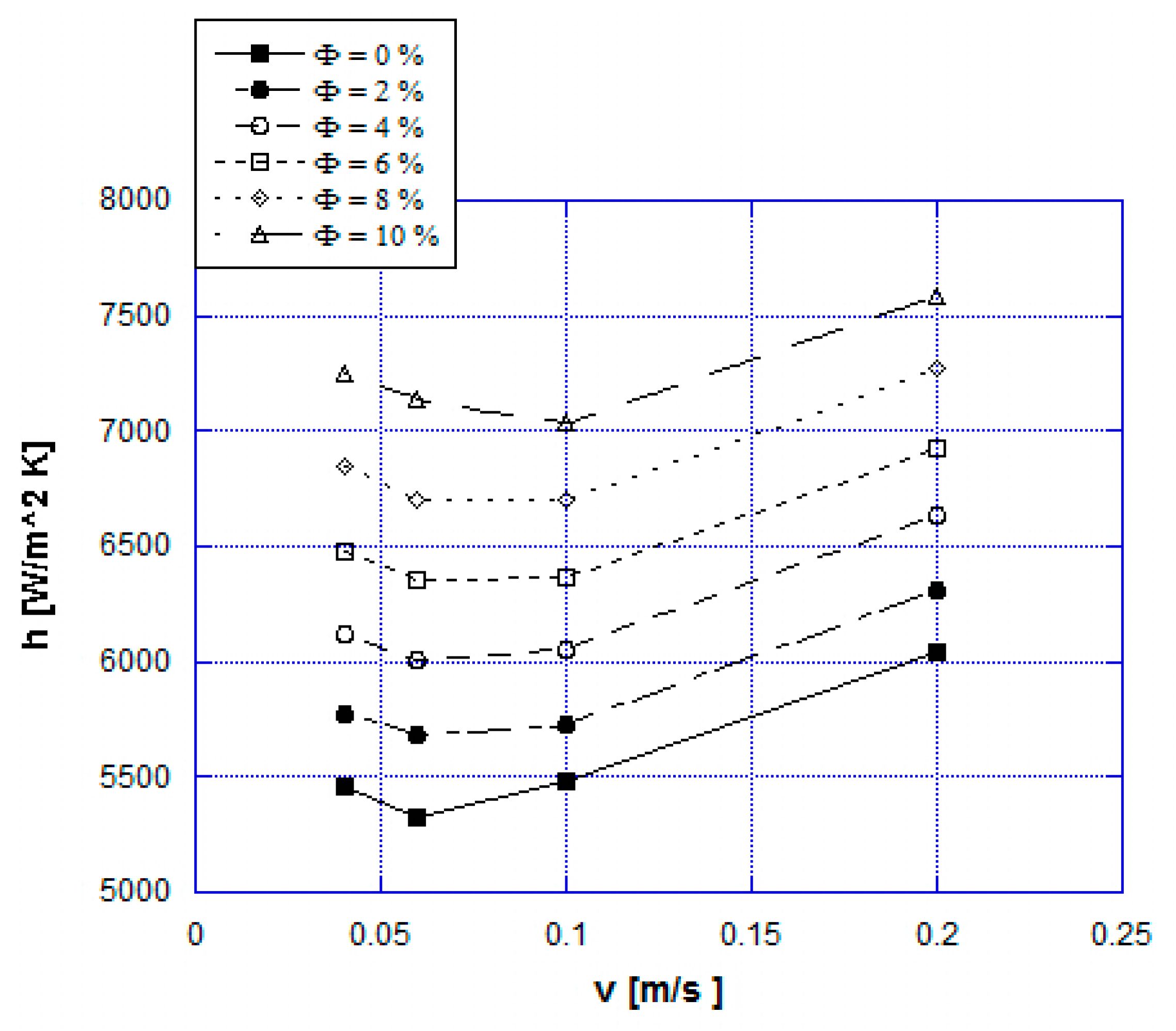
Figure 6 reports the convective heat transfer coefficient as a function of nanofluid velocity parametrized for nanoparticle volume fraction. By fixing the velocity, one can appreciate the enhancement of the heat transfer coefficient with increasing nanoparticle volume fraction. A maximum h-enhancement of +34% was registered if the nanoparticles concentration increased from 0% up to 10% with v = 0.06 m/s, and +30% of heat transfer improvement for nanoparticles concentration increased from 0 to 10% was estimated as the mean value with respect to the nanofluid velocity. Moreover, one can notice that each curve plotted in Figure 6 had minimum points located at v = 0.06 m/s for low ϕ and at v = 0.10 m/s when the nanoparticles concentration increased. We found an explanation for this trend by analyzing each contribution of the nanofluid energy equation:
ρ nf C nf ( T nf t + u T nf x + v T nf y ) = k nf ( 2 T nf x 2 + 2 T nf y 2 )
The left side represents the inertia and the convection terms, whereas, at the second member, there was the conduction term. Thus, the mean convective heat flux depended on fluid inertia, convection, and conduction. Convection and conduction promoted heat transfer, whereas inertia played a negative role.
At very low fluid velocities (0.04 m/s), inertia prevailed beyond conduction and convection, and this was detrimental for the heat exchange between fluid and solid. Consequently, the fluid temperature was higher, and this effect improved the fluid conductivity, increasing the conductivity heat exchange. By increasing the fluid velocity (0.06 m/s), the convection was slightly improved; therefore, the fluid temperature slightly decreased, consequently decreasing the conductive heat transfer. Therefore, the heat transfer coefficient slightly decreased. With a further increase of the fluid velocity (0.1 m/s), the convection term prevailed (rather than fluid inertia), and the heat transfer coefficient increased with fluid velocity. Therefore, at very low velocities, inertia played a dominant role in the heat transfer.
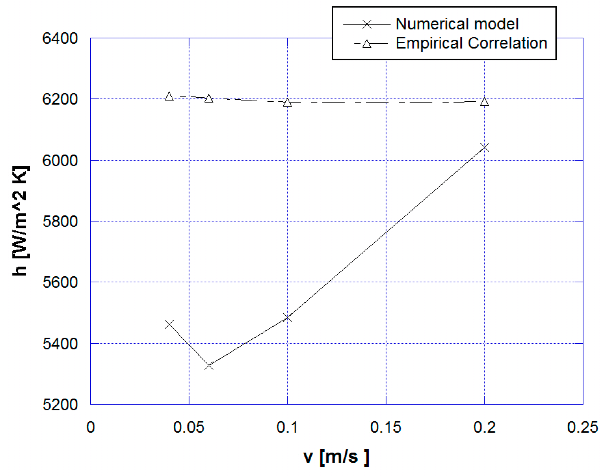
Indeed, taking as reference the convective heat transfer coefficients evaluated for the base fluid cases (ϕ = 0%), we estimated the corresponding h by means of the empirical correlations based on the dimensionless numbers of the forced convection (Reynolds and Prandtl numbers) and on the properties of the fluid itself at the reference temperature. The correlations used considered a fully developed and stationary laminar flow. Figure 7 reports a comparison between the convective heat transfer coefficients carried out from numerical simulations and the ones evaluated through empirical correlations for ϕ = 0%. Different trends could be observed, for example, the heat transfer coefficient from correlation was almost constant, whereas the numerical one first slightly decreased and then increased. Indeed, when the velocity increased over the threshold value, the convective term prevailed over the inertia, contributing to heat transfer enhancement. The correlations were based on steady state equations and therefore did not account for the inertia term. Furthermore, correlations always overpredicted heat transfer coefficients (from a minimum of +2.5% to a maximum of +16.5%) because they did not consider the detrimental effect of the inertia term. At the highest (0.2 m/s) fluid velocity, the difference between correlation and numerical model coefficient was at the minimum because the effect of inertia was lower.
To better analyze the effect of the heat transfer enhancement with nanofluids on the performance of the active barocaloric regenerator, we introduced an outstanding parameter as follows:
Δ T ABR = 1 τ τ + n θ 2 τ + n θ T nf ( L , y , t ) d t 1 τ 3 τ + n θ 4 τ + n θ T nf ( 0 , y , t ) d t   ,
Δ T ABR is a parameter used to evaluate the maximum temperature drop across the ABR since it measures the temperature difference between the nanofluid exiting the regenerator at the hot side (x = L) during the cold-to-hot flowing phase and at the cold side (x = 0) during the hot-to-cold flowing phase. To this hope, Figure 8 reports the trends of Δ T ABR as a function of nanofluid velocity parametrized for nanoparticles volume fraction. As a general trend, it was possible to observe that there was a maximum of Δ T ABR , located at v = 0.06 m/s for each volume fraction. At a fixed volume fraction, the Δ T ABR   first increased with fluid velocity, where it reached a maximum and then decreased. Indeed, by increasing the fluid velocity, the convective heat transfer coefficient also increased, as shown in Figure 6. Therefore, there was an optimal fluid velocity (around 0.06 m/s) corresponding to the point where the fluid could utilize the entire energy available from the barocaloric effect, and it was independent from the particles volume fraction. Further fluid flow perturbed the temperature profile of the ABR, reducing the temperature difference between the fluid and the regenerator. The latter quickly became overwhelmed by the fluid flow, and the efficiency of the heat transfer decreased. Figure 8 also shows that, at fixed fluid velocity, the Δ T ABR   increased by augmenting the particles volume fraction. Therefore, working with nanofluids had a positive influence on the convective barocaloric-refrigerant-auxiliary-fluid heat exchange. With increasing nanofluid velocity, the nanoparticle concentration had a lower influence on the augmentation Δ T ABR , because the efficiency of the heat exchange decreased. Therefore, at v = 0.2 m/s, the points appeared closer to each other than had occurred at lower velocities.

6. Conclusions

In this paper, the effects of working with nanofluids on heat transfer enhancement in an active barocaloric refrigerator were investigated through a two-dimensional finite element method. The ABR employed a barocaloric vulcanizing rubber as solid-state refrigerant and Cu + 50% ethylene glycol - 50% water nanofluids as auxiliary fluid. The nanoparticle volume fraction of the nanofluid varied from 0% to 10%, and the main indicators significative for evaluating the heat transfer were carried out. The results reveal that, as a general trend, the effect of adding 10% Cu nanoparticles in the water/ethylene-glycol mixture carries to +30% as a medium increment of heat transfer enhancement. Such an increment was detected with the ABR operating at different velocities and also influenced the energy parameters of the regenerator such as ∆TABR. Therefore, the addition of nanofluids in an active barocaloric refrigerator has many benefits.

Author Contributions

The following statements should be used “conceptualization, A.G., A.M. and C.M.; methodology, A.G.; software, C.M.; validation, A.G.; formal analysis, A.G. and C.M.; investigation, C.M.; resources, C.A. and A.M.; data curation, A.G., A.M. and C.M.; writing—original draft preparation, C.M.; writing—review and editing, A.G.; visualization, C.A. and A.M.; supervision, C.A., A.G. and A.M.; project administration, C.A. and A.G.; funding acquisition, C.A. and A.G.”

Funding

This research received no external funding.

Conflicts of Interest

The authors declare no conflict of interest.

Nomenclature

Roman symbols
Cspecific heat, J kg−1 K−1
hconvective heat transfer coefficient, W m−2 K−1
kthermal conductivity, W m−1 K−1
Llength of the regenerator in fluid flow direction, m
nempirical shape factor
ppressure, Pa
Qpower density associated to barocaloric effect, W m−3
qnumber of ABR cycles
q ˙ convective heat flux, W m−2
Ttemperature, K
ttime, s
ulongitudinal fluid velocity, m s−1
vorthogonal fluid velocity, m s−1
xlongitudinal spatial coordinate, m
yorthogonal spatial coordinate, m
Greek symbols
Δfinite difference
partial derivative
δinfinitesimal difference
ε ¯ infinitesimal quantity
θperiod of the ABR cycle, s
μdynamic viscosity, Pa s
νcinematic viscosity, m2 s−1
ρdensity, kg m−3
φvolume fraction
τperiod of each step of the ABR cycle, s
Subscripts
adadiabatic
ABRactive barocaloric refrigerator
bfbase fluid
Ccold heat exchanger
cconvective
Ddecompression
Hhot heat exchanger
nfnanofluid
npnanoparticles
ssolid

References

  1. World Bank Open Data—Electric Power Consumption (kWh per Capita). Available online: https://data.worldbank.org/indicator/EG.USE.ELEC.KH.PC (accessed on 29 May 2019).
  2. Protocol, Montreal. Montreal Protocol on Substances that Deplete the Ozone Layer; United Nation Environment Program (UN): New York, NY, USA, 1987. [Google Scholar]
  3. Protocol, Kyoto. Kyoto Protocol to the United Nation Framework Convention on Climate Change; United Nation Environment Program (UN): Kyoto, Japan, 1997. [Google Scholar]
  4. Heath, E.A. Amendment to the Montreal Protocol on Substances that Deplete the Ozone Layer (Kigali Amendment). Int. Legal Mater. 2017, 56, 193–205. [Google Scholar] [CrossRef] [Green Version]
  5. Greco, A.; Mastrullo, R.; Palombo, A. R407C as an alternative to R22 in vapour compression plant: An experimental study. Int. J. Energy Res. 1997, 21, 1087–1098. [Google Scholar] [CrossRef]
  6. Greco, A.; Vanoli, G.P. Flow boiling heat transfer with HFC mixtures in a smooth horizontal tube. Part II: Assessment of predictive methods. Exp. Therm. Fluid Sci. 2005, 29, 199–208. [Google Scholar] [CrossRef]
  7. Aprea, C.; Greco, A.; Maiorino, A. The substitution of R134a with R744: An exergetic analysis based on experimental data. Int. J. Refrig. 2013, 36, 2148–2159. [Google Scholar] [CrossRef]
  8. Brown, D.; Stout, T.; Dirks, J.; Fernandez, N. The Prospects of Alternatives to Vapor Compression Technology for Space Cooling and Food Refrigeration Applications. Energy Eng. 2012, 109, 7–20. [Google Scholar] [CrossRef] [Green Version]
  9. Goetzler, W.; Zogg, R.; Young, J.; Johnson, C. Alternatives to vapor-compression HVAC technology. ASHRAE J. 2014, 56, 12. [Google Scholar]
  10. Bellos, E.; Tzivanidis, C. CO2 Transcritical Refrigeration Cycle with Dedicated Subcooling: Mechanical Compression vs. Absorption Chiller. Appl. Sci. 2019, 9, 1605. [Google Scholar] [CrossRef]
  11. Li, S.; Jeong, J.W. Energy Performance of Liquid Desiccant and Evaporative Cooling-Assisted 100% Outdoor Air Systems under Various Climatic Conditions. Energies 2018, 11, 1377. [Google Scholar] [CrossRef]
  12. Brown, J.S.; Domanski, P.A. Review of alternative cooling technologies. Appl. Therm. Eng. 2014, 64, 252–262. [Google Scholar] [CrossRef]
  13. Czernuszewicz, A.; Kaleta, J.; Lewandowski, D. Multicaloric effect: Toward a breakthrough in cooling technology. Energy Convers. Manag. 2018, 178, 335–342. [Google Scholar] [CrossRef]
  14. Fähler, S.; Rößler, U.K.; Kastner, O.; Eckert, J.; Eggeler, G.; Emmerich, H.; Entel, P.; Müller, S.; Quandt, E.; Albe, K. Caloric Effects in Ferroic Materials: New Concepts for Cooling. Adv. Eng. Mater. 2012, 14, 10–19. [Google Scholar] [CrossRef]
  15. Kitanovski, A.; Plaznik, U.; Tomc, U.; Poredoš, A. Present and future caloric refrigeration and heat-pump technologies. Int. J. Refrig. 2015, 57, 288–298. [Google Scholar] [CrossRef]
  16. Aprea, C.; Greco, A.; Maiorino, A.; Masselli, C. Solid-state refrigeration: A comparison of the energy performances of caloric materials operating in an active caloric regenerator. Energy 2018, 165, 439–455. [Google Scholar] [CrossRef]
  17. Pecharsky, V.K.; Gschneidner, K.A., Jr. Magnetocaloric effect and magnetic refrigeration. J. Magn. Magn. Mater. 1999, 200, 44–56. [Google Scholar] [CrossRef]
  18. Ohnishi, T.; Soejima, K.; Yamashita, K.; Wada, H. Magnetocaloric Properties of (MnFeRu) 2 (PSi) as Magnetic Refrigerants near Room Temperature. Magnetochemistry 2017, 3, 6. [Google Scholar] [CrossRef]
  19. Thang, N.; Dijk, N.; Brück, E. Tuneable giant magnetocaloric effect in (Mn, Fe) 2 (P, Si) materials by Co-B and Ni-B co-doping. Materials 2016, 10, 14. [Google Scholar] [CrossRef] [PubMed]
  20. Scott, J.F. Electrocaloric materials. Annu. Rev. Mater. Res. 2011, 41, 229–240. [Google Scholar] [CrossRef]
  21. Sun, X.; Huang, H.; Jafri, H.M.; Wang, J.; Wen, Y.; Dang, Z.M. Wide Electrocaloric Temperature Range Induced by Ferroelectric to Antiferroelectric Phase Transition. Appl. Sci. 2019, 9, 1672. [Google Scholar] [CrossRef]
  22. Jiang, Z.Y.; Zheng, G.P.; Zheng, X.C.; Wang, H. Exceptionally high negative electro-caloric effects of poly (VDF–co–TrFE) based nanocomposites tuned by the geometries of barium titanate nanofillers. Polymers 2017, 9, 315. [Google Scholar] [CrossRef]
  23. Wu, Y.; Ertekin, E.; Sehitoglu, H. Elastocaloric cooling capacity of shape memory alloys—Role of deformation temperatures, mechanical cycling, stress hysteresis and inhomogeneity of transformation. Acta Mater. 2017, 135, 158–176. [Google Scholar] [CrossRef]
  24. Strässle, T.; Furrer, A. Cooling by adiabatic (DE) pressurization—The barocaloric effect. High Press. Res. 2000, 17, 325–333. [Google Scholar] [CrossRef]
  25. Aprea, C.; Greco, A.; Maiorino, A.; Masselli, C. Magnetic refrigeration: An eco-friendly technology for the refrigeration at room temperature. J. Phys. Conf. Ser. 2015, 655, 012026. [Google Scholar] [CrossRef]
  26. Saito, A.T.; Kobayashi, T.; Kaji, S.; Li, J.; Nakagome, H. Environmentally Friendly Magnetic Refrigeration Technology Using Ferromagnetic Gd Alloys. Int. J. Environ. Sci. Dev. 2016, 7, 316–320. [Google Scholar] [CrossRef] [Green Version]
  27. Aprea, C.; Greco, A.; Maiorino, A.; Masselli, C. Electrocaloric refrigeration: An innovative, emerging, eco-friendly refrigeration technique. J. Phys. Conf. Ser. 2017, 796, 012019. [Google Scholar] [CrossRef]
  28. Aprea, C.; Greco, A.; Maiorino, A.; Masselli, C. The environmental impact of solid-state materials working in an active caloric refrigerator compared to a vapor compression cooler. Int. J. Heat Technol. 2018, 36, 1155–1162. [Google Scholar] [CrossRef]
  29. Kawanami, T.; Hirano, S.; Fumoto, K.; Hirasawa, S. Evaluation of fundamental performance on magnetocaloric cooling with active magnetic regenerator. Appl. Therm. Eng. 2011, 31, 1176–1183. [Google Scholar] [CrossRef]
  30. Aprea, C.; Greco, A.; Maiorino, A.; Masselli, C. A comparison between rare earth and transition metals working as magnetic materials in an AMR refrigerator in the room temperature range. Appl. Therm. Eng. 2015, 91, 767–777. [Google Scholar] [CrossRef]
  31. Valant, M. Electrocaloric materials for future solid-state refrigeration technologies. Prog. Mater. Sci. 2012, 57, 980–1009. [Google Scholar] [CrossRef]
  32. Aprea, C.; Greco, A.; Maiorino, A.; Masselli, C. A comparison between different materials in an active electrocaloric regenerative cycle with a 2D numerical model. Int. J. Refrig. 2016, 69, 369–382. [Google Scholar] [CrossRef]
  33. Wang, H.; Huang, H.; Xie, J. Effects of Strain Rate and Measuring Temperature on the Elastocaloric Cooling in a Columnar-Grained Cu71Al17. 5Mn11. 5 Shape Memory Alloy. Metals 2017, 7, 527. [Google Scholar] [CrossRef]
  34. Tušek, J.; Engelbrecht, K.; Millán-Solsona, R.; Mañosa, L.; Vives, E.; Mikkelsen, L.P.; Pryds, N. The Elastocaloric Effect: A Way to Cool Efficiently. Adv. Energy Mater. 2015, 5, 1500361. [Google Scholar] [CrossRef]
  35. Strässle, T.; Furrer, A.; Dönni, A.; Komatsubara, T. Barocaloric effect: The use of pressure for magnetic cooling in Ce 3 Pd 20 Ge 6. J. Appl. Phys. 2002, 91, 8543–8545. [Google Scholar] [CrossRef]
  36. Plaznik, U.; Tušek, J.; Kitanovski, A.; Poredoš, A. Numerical and experimental analyses of different magnetic thermodynamic cycles with an active magnetic regenerator. Appl. Therm. Eng. 2013, 59, 52–59. [Google Scholar] [CrossRef]
  37. Tušek, J.; Kitanovski, A.; Poredoš, A. Geometrical optimization of packed-bed and parallel-plate active magnetic regenerators. Int. J. Refrig. 2013, 36, 1456–1464. [Google Scholar] [CrossRef]
  38. Aprea, C.; Greco, A.; Maiorino, A. An application of the artificial neural network to optimise the energy performances of a magnetic refrigerator. Int. J. Refrig. 2017, 82, 238–251. [Google Scholar] [CrossRef]
  39. Teyber, R.; Trevizoli, P.V.; Christiaanse, T.V.; Govindappa, P.; Niknia, I.; Rowe, A. Semi-analytic AMR element model. Appl. Therm. Eng. 2018, 128, 1022–1029. [Google Scholar] [CrossRef]
  40. Pecharsky, V.K.; Gschneidner, K.A., Jr. Advanced magnetocaloric materials: What does the future hold? Int. J. Refrig. 2006, 29, 1239–1249. [Google Scholar] [CrossRef]
  41. Crossley, S.; Mathur, N.D.; Moya, X. New developments in caloric materials for cooling applications. AIP Adv. 2015, 5, 067153. [Google Scholar] [CrossRef]
  42. Moya, X.; Kar-Narayan, S.; Mathur, N.D. Caloric materials near ferroic phase transitions. Nat. Mater. 2014, 13, 439–450. [Google Scholar] [CrossRef]
  43. Liu, Y.; Scott, J.F.; Dkhil, B. Some strategies for improving caloric responses with ferroelectrics. APL Mater. 2016, 4, 064109. [Google Scholar] [CrossRef] [Green Version]
  44. Yu, B.; Liu, M.; Egolf, P.W.; Kitanovski, A. A review of magnetic refrigerator and heat pump prototypes built before the year 2010. Int. J. Refrig. 2010, 33, 1029–1060. [Google Scholar] [CrossRef]
  45. Sari, O.; Balli, M. From conventional to magnetic refrigerator technology. Int. J. Refrig. 2014, 37, 8–15. [Google Scholar] [CrossRef]
  46. Franco, V.; Blazquez, J.S.; Amiano, A.C. Field dependence of the magnetocaloric effect in materials with a second order phase transition: A master curve for the magnetic entropy change. Appl. Phys. Lett. 2006, 89, 222512. [Google Scholar] [CrossRef]
  47. Aprea, C.; Greco, A.; Maiorino, A. The use of the first and of the second order phase magnetic transition alloys for an AMR refrigerator at room temperature: A numerical analysis of the energy performances. Energy Convers. Manag. 2013, 70, 40–55. [Google Scholar] [CrossRef]
  48. Correia, T.; Zhang, Q. Electrocaloric Materials; Springer: Berlin, Germany, 2014. [Google Scholar]
  49. Qian, S.; Geng, Y.; Wang, Y.; Ling, J.; Hwang, Y.; Radermacher, R.; Takeuchi, I.; Cui, J. A review of elastocaloric cooling: Materials, cycles and system integrations. Int. J. Refrig. 2016, 64, 1–19. [Google Scholar] [CrossRef]
  50. Greco, A.; Aprea, C.; Maiorino, A.; Masselli, C. A review of the state of the art of solid-state caloric cooling processes at room-temperature before 2019. Int. J. Refrig. 2019. [Google Scholar] [CrossRef]
  51. Lu, B.; Liu, J. Mechanocaloric materials for solid-state cooling. Sci. Bull. 2015, 60, 1638–1643. [Google Scholar] [CrossRef]
  52. Aprea, C.; Greco, A.; Maiorino, A.; Masselli, C. A comparison between different materials with mechanocaloric effect. Int. J. Heat Technol. 2018, 36, 801–807. [Google Scholar] [CrossRef] [Green Version]
  53. Bom, N.M.; Imamura, W.; Usuda, E.O.; Paixão, L.S.; Carvalho, A.M.G. Giant Barocaloric Effects in Natural Rubber: A Relevant Step toward Solid-State Cooling. ACS Macro Lett. 2017, 7, 31–36. [Google Scholar] [CrossRef] [Green Version]
  54. Bom, N.M.; Usuda, E.O.; Guimarães, G.M.; Coelho, A.A.; Carvalho, A.M.G.; Carvalho, A. Note: Experimental setup for measuring the barocaloric effect in polymers: Application to natural rubber. Rev. Sci. Instrum. 2017, 88, 046103. [Google Scholar] [CrossRef] [Green Version]
  55. Yu, W.; France, D.M.; Routbort, J.L.; Choi, S.U.S. Review and Comparison of Nanofluid Thermal Conductivity and Heat Transfer Enhancements. Heat Transf. Eng. 2008, 29, 432–460. [Google Scholar] [CrossRef]
  56. Choi, S.U.S. Enhancing thermal conductivity of fluids with nanoparticles. Dev. Appl. Non-Newton. Flows 1995, 66, 99–105. [Google Scholar]
  57. Mohamad, N.A.; Azis, N.; Jasni, J.; Kadir, A.; Abidin, M.Z.; Yunus, R.; Yaakub, Z. Impact of Fe3O4, CuO and Al2O3 on the AC Breakdown Voltage of Palm Oil and Coconut Oil in the Presence of CTAB. Energies 2019, 12, 1605. [Google Scholar] [CrossRef]
  58. Irfan, S.A.; Shafie, A.; Yahya, N.; Zainuddin, N. Mathematical Modeling and Simulation of Nanoparticle-Assisted Enhanced Oil Recovery—A Review. Energies 2019, 12, 1575. [Google Scholar] [CrossRef]
  59. Hussain, M.I.; Kim, J.H.; Kim, J.T. Nanofluid-Powered Dual-Fluid Photovoltaic/Thermal (PV/T) System: Comparative Numerical Study. Energies 2019, 12, 775. [Google Scholar] [CrossRef]
  60. Fal, J.; Mahian, O.; Żyła, G. Nanofluids in the Service of High Voltage Transformers: Breakdown Properties of Transformer Oils with Nanoparticles, a Review. Energies 2018, 11, 2942. [Google Scholar] [CrossRef]
  61. Kristiawan, B.; Santoso, B.; Wijayanta, A.; Aziz, M.; Miyazaki, T. Heat transfer enhancement of TiO2/water nanofluid at laminar and turbulent flows: A numerical approach for evaluating the effect of nanoparticle loadings. Energies 2018, 11, 1584. [Google Scholar] [CrossRef]
  62. Sun, X.H.; Yan, H.; Massoudi, M.; Chen, Z.H.; Wu, W.T. Numerical simulation of nanofluid suspensions in a geothermal heat exchanger. Energies 2018, 11, 919. [Google Scholar] [CrossRef]
  63. Bellos, E.; Tzivanidis, C. Optimization of a solar-driven trigeneration system with nanofluid-based parabolic trough collectors. Energies 2017, 10, 848. [Google Scholar] [CrossRef]
  64. Kumar, S.A.; Meenakshi, K.S.; Narashimhan, B.R.V.; Srikanth, S.; Arthanareeswaran, G. Synthesis and characterization of copper nanofluid by a novel one-step method. Mater. Chem. Phys. 2009, 113, 57–62. [Google Scholar] [CrossRef]
  65. Chiba, Y. Enhancements of thermal performances of an active magnetic refrigeration device based on nanofluids. Mechanics 2017, 23, 31–38. [Google Scholar] [CrossRef]
  66. Mugica, I.; Roy, S.; Poncet, S.; Bouchard, J.; Nesreddine, H. Exergy analysis of a parallel-plate active magnetic regenerator with nanofluids. Entropy 2017, 19, 464. [Google Scholar] [CrossRef]
  67. Aprea, C.; Cardillo, G.; Greco, A.; Maiorino, A.; Masselli, C. A comparison between experimental and 2D numerical results of a packed-bed active magnetic regenerator. Appl. Therm. Eng. 2015, 90, 376–383. [Google Scholar] [CrossRef]
  68. Aprea, C.; Cardillo, G.; Greco, A.; Maiorino, A.; Masselli, C. A rotary permanent magnet magnetic refrigerator based on AMR cycle. Appl. Therm. Eng. 2016, 101, 699–703. [Google Scholar] [CrossRef]
  69. Aprea, C.; Greco, A.; Maiorino, A.; Masselli, C. Energy performances and numerical investigation of solid-state magnetocaloric materials used as refrigerant in an active magnetic regenerator. Therm. Sci. Eng. Prog. 2018, 6, 370–379. [Google Scholar] [CrossRef]
  70. Imamura, W.; Usuda, E.O.; Paixão, L.S.; Bom, N.M.; Gomes, A.M.; Carvalho, A.M.G. Supergiant barocaloric effects in acetoxy silicone rubber around room temperature. arXiv 2017, arXiv:1710.01761. [Google Scholar]
  71. Ashrae. 2009 ASHRAE Handbook—Fundamentals (SI Edition); Ashrae: Atlanta, GA, USA, 2009. [Google Scholar]
  72. Bianco, V.; Vafai, K.; Manca, O.; Nardini, S. Heat Transfer Enhancement with Nanofluids; CRC Press: Boca Raton, FL, USA, 2015. [Google Scholar]
  73. Brinkman, H.C. The viscosity of concentrated suspensions and solutions. J. Chem. Phys. 1952, 20, 571. [Google Scholar] [CrossRef]
  74. Hamilton, R.L.; Crosser, O.K. Thermal conductivity of heterogeneous two-component systems. Ind. Eng. Chem. Fund. 1962, 1, 187–191. [Google Scholar] [CrossRef]
Figure 1. The four steps composing the active barocaloric regenerative (ABR) refrigerant cycle.
Energies 12 02902 g001
Figure 2. The geometry of the parallel-plates barocaloric regenerator.
Energies 12 02902 g002
Figure 3. Temperature change due to barocaloric effects (BCE) and detected in acetoxy silicone rubber (ASR) during adiabatic decompression (∆p = 0.390 GPa).
Energies 12 02902 g003
Figure 4. Q term constructing for ASR during adiabatic decompression process from 0.390 GPa to 0 GPa.
Energies 12 02902 g004
Figure 5. Solids and nanofluids temperatures averaged alongside one channel (x direction) and over time during the fourth step of the ABR cycle as a function of volume fraction and for the nanofluid velocities: (a) 0.04 m/s; (b) 0.06 m/s; (c) 0.10 m/s; (d) 0.20 m/s.
Energies 12 02902 g005
Figure 6. Convective heat transfer coefficient as a function of nanofluid velocity parametrized for nanoparticles volume fraction.
Energies 12 02902 g006
Figure 7. Comparison between the convective heat transfer coefficients carried out from the numerical model and the ones evaluated through empirical correlations.
Energies 12 02902 g007
Figure 8. Δ T ABR as a function of nanofluid velocity parametrized for nanoparticles volume fraction.
Energies 12 02902 g008
Table 1. Thermal and physical features of acetoxy silicone rubber.
MaterialTpeak [K]Δp [GPa]∆Tad,max [K]Density [kg/m3]Thermal Conductivity [W/mK]
ASR2980.39041.19601.48
Table 2. Thermal features of Cu.
MaterialSpecific Heat [J/kgK]Density [kg/m3]Thermal Conductivity [W/mK]
Cu3838933401