Article

The Impact of Zero-Mode Inrush Current of T-Hin on Zero-Sequence Overcurrent Protection and an Improved Protection with the Second Harmonic Restraint

1
State Key Laboratory of Advance Electromagnetic Engineering and Technology, Huazhong University of Science and Technology, Wuhan 430074, China
2
Power Dispatching Control Center of Guangdong Power Grid, Guangzhou 510000, China
*
Author to whom correspondence should be addressed.
Energies 2019, 12(15), 2911; https://doi.org/10.3390/en12152911
Submission received: 24 June 2019 / Revised: 18 July 2019 / Accepted: 25 July 2019 / Published: 29 July 2019
(This article belongs to the Special Issue Advanced Techniques for Electronic Power and Energy Systems)

Abstract

:
In recent years, the zero-mode inrush current of high-impedance transformer with built-in high-voltage winding (T-Hin), which has large amplitude and decays slowly, causes the misoperation of zero-sequence overcurrent protection. Compared with magnetizing inrush current, the waveform of zero-mode inrush current is inconsistent and irregular, and few researches have proposed the mathematical analysis as well as the improved protection using waveform characteristics. In this paper, the mathematical expression of transformer zero-mode inrush current is derived. Further considering the parameter differences, the zero-mode inrush current of T-Hin is larger, which tends to cause the misoperation. The mathematical waveforms fit well with the recorded waveforms. Both recorded waveforms and mathematical waveforms in various conditions prove that the second harmonic ratio (the ratio between the second harmonic and first harmonic) of zero-mode inrush current is significant. Based on the above analysis, a criterion based on the second harmonic ratio restraint of zero-mode inrush current is proposed. If the second harmonic ratio exceeds the setting value, it is considered that the inrush current is generated and sends a signal to restrain the protection. The theoretical setting value of the proposed criterion and the practical engineering method for determining the setting value are obtained.

1. Introduction

In the process of transformer energization or the voltage recovery after the removal of external fault, a large magnetizing inrush current (including sympathetic inrush current) will occur [1,2,3]. The magnitude of inrush current may be as high as ten or more times that of transformer rated current. The fault current is caused by short circuit fault in the power grid. Though the magnitude of inrush current may be less compared to short circuit current, the frequency and its duration can lead to more adverse effects compared to other faults. An inrush current is a transient current with high amplitude and contains a significant and slowly decaying DC component. So far the physical mechanism of magnetizing inrush current, the discrimination between magnetizing inrush current and fault current, the impact on transformer differential protection and its countermeasures have been extensively discussed in many researches [4,5,6,7,8]. However, the zero-mode inrush current, which is the sum of the instantaneous values of the three-phase magnetizing inrush current (3i0 = iA + iB + iC), has hardly been discussed in-depth. It may cause the misoperation of zero-sequence overcurrent protection of nearby equipment (backup protection) when the transformer is energized. The zero-sequence current obtained by the protection, which is the core cause of misoperation, is the fundamental frequency component of the zero-mode inrush current. The zero-mode current and the zero-sequence current with different physical meaning are often misclassified. Compared with zero-sequence current, zero-mode inrush current has richer frequency content. The zero-sequence current (3I0) is the fundamental RMS value of the zero-mode current (3i0), and the zero-mode current is the sum of the three-phase currents (3i0 = iA + iB + iC), as shown in Figure A1. The zero-mode inrush current is the zero-mode current which is generated when the transformer is energized. The zero-mode inrush current belongs to the zero-mode current.
The misoperations did not occurred frequently for a long time in the past and did not attract enough attention. With the increase of grid capacity [9], some new kinds of high-impedance transformer have been widely used [10,11] to limit short-circuit current [12]. However, when the high-impedance transformer (especially the high-impedance transformer with built-in high-voltage winding, T-Hin for short) is energized, the zero-sequence overcurrent protection of the bus connection switch and even the upper-level line will misoperate beyond their protection range, which seriously threatens the safety and stability of the power grid. By analysing the recorded waveforms, the initial value of zero-mode inrush current, as well as its fundamental frequency component obtained by the zero-sequence current protection, is much larger than usual. After the delay time of the zero-sequence overcurrent protection, its value is still larger than the setting value, which is the direct cause of the misoperation. The criterion of zero-sequence overcurrent protection cannot discriminate between zero-mode inrush current and grounding fault current. In order to avoid misoperation, the zero-mode inrush current should be distinguished separately. In order to accurately obtain the waveform characteristics and propose identification criterions, it is urgent to carry out the mathematical analysis for the zero-mode inrush current and obtain its analytical model.
The zero-mode inrush current has been noticed for a long time [13]. References [14,15] illustrate that the zero-mode current is generated by three-phase asymmetric magnetizing inrush current, and [14,15] give the zero-mode inrush current waveforms under different remanence and closing angle through simulation. References [16,17,18] analyse the characteristics of zero-mode inrush current and its impact on the zero-sequence overcurrent protection of transformer, line and bus bar through simulation. Reference [19] takes use of centre-of-gravity amplitude of the phase space distribution to identify the zero-mode inrush current and carries out the simulations in a 12-pulse converter unit scenario, where two parallel converter transformers are connected by Yd and Yy respectively. However, it cannot be proved whether it can solve the problem of zero-sequence protection misoperation caused by the single transformer energization. Additionally, the setting value of the criterion is obtained only by simulation experience without theoretical explanation. Reference [20] derives the zero-mode current and equivalent circuit of transformer and analyses the determinants of waveform of the zero-mode inrush current. In order to solve the problem of misoperation of zero-sequence overcurrent protection, the paper points out two possible research directions for subsequent implementation: one is “reducing the self-leakage inductance of secondary delta winding”, the other is “the second harmonic ratio criterion”. However, this method has not yet carried out theoretical proof of validity, nor does it have a method for determining the setting value. In summary, the above papers studied the zero-mode inrush current by means of simulations, and few theoretical and mathematical analytical studies on the characteristics of zero-mode inrush current and its waveforms have been proposed. The simulation is carried out under specific scenarios and parameters. The conclusions about the zero-mode inrush current and the determination of setting value of the identification criteria are not rigorous. There is still a lack of improved research on zero-sequence overcurrent protection. There are many accidents in substations where the zero-sequence overcurrent protection misoperated when the T-Hin was energized. The direct cause is that the zero-mode inrush current and its fundamental component (zero-sequence current) of T-Hin has a larger amplitude and exceeds the zero-sequence protection setting value for a long time. In order to propose a method to avoid misoperation, the zero-mode inrush current should be studied comprehensively. The waveforms of zero-mode inrush are inconsistent and irregular, and few studies have proposed the mathematical analysis as well as the improved protection using waveform characteristics. In this paper, based on the derivation of single-phase magnetizing inrush current, the mathematical expression of the zero-mode inrush current is derived. According to the mathematical expression and parameters of the T-Hin, it is found that the zero-mode inrush current of T-Hin is larger, which is more likely to cause the misoperation of zero-sequence overcurrent protection. The waveform obtained by mathematical expression fits well with the recorded waveforms, which verifies the correctness of mathematical expression. Both recorded waveforms and mathematical waveforms in various conditions (no remanence, symmetric remanence and random remanence in the three-phase iron core) prove the second harmonic ratio of zero-mode inrush current is high. A criterion based on the second harmonic ratio restraint of zero-mode inrush current is proposed. The theoretical setting value of the proposed criterion and the practical engineering method for determining the setting value are obtained.

2. Analytical Model of Zero-Mode Inrush Current of Y0/Δ Transformer

2.1. Derivation of Single Transformer Magnetizing Inrush Current

Figure A2, Figure A3, Figure A4 and Figure A5 are four sets of recorded waveforms obtained at the substation. Figure A1 and Figure A2 are the same recorded waveform. As shown in Figure A1, Figure A2, Figure A3, Figure A4 and Figure A5, the phase current (iA, iB, iC) and zero-mode current (3i0) are slowly attenuated after the circuit breaker is connected, and the attenuation process is long and will last for many seconds. However, the effect of attenuation is small during several cycles after connecting. Therefore, although the inrush current is a transient process during this period, the inrush current waveform can be treated as a periodic function for obtaining the feature in several cycles. Therefore, it is considered that there is no attenuation when the formula is derived, and the resistance is ignored. First, the magnetizing inrush current of the single-phase transformer is analysed. For the closing loop circuit, ignoring the resistance [21], the ψ can be calculated as follows:
d ψ d t = U s sin ( ω t + α )
where, Ussin(ωt + α) is system voltage instantaneous value of phase A. α is the angle at which the transformer was connected. We call α the “closing angle”. ψ is the total flux linkage of closing loop circuit. It can be solved by Equation (1):
ψ = U s ω [ cos α cos ( ω t + α ) ] + ψ r
where, ψ|t=0 = ψr, ψr is the core remanence, ψr = WSBr, and Br is the remanent magnetic flux density, W is the number of winding turns and S is the cross-sectional area.
The magnetization characteristic curve of the iron core is shown in Figure 1. The magnetizing characteristic curve can be expressed as ψ~i or B~H. According to the description of the magnetization curve by IEC [22], it is reasonably assumed that the curve can be simplified to the double line model, as shown in dotted line in Figure 1. Explanation of terms in Figure 1 see Appendix B. Due to the nonlinearity of the core, the differential inductance represented by the slope is a linear inductance including the system inductance and the leakage inductance.
As shown in Figure 1, the current is:
i = { 0 ψ < ψ Sat ψ ψ Sat L s + L σ + M air ψ > ψ Sat
where, ψSat = WSBSat = μ0WSJSat, JSat is the saturation magnetization. According to Equations (2) and (3), If the inrush current occur, the magnetizing current of the single-phase transformer is:
i = U s ω L [ cos α cos ( ω t + α ) ω μ 0 W S J S a t ω ψ r U s ]
where: L = Ls + Lσ + Mair. Us = ωWSBs. ψr = WSBr. Equation (4) becomes:
i = U s ω L [ cos α cos ( ω t + α ) B S a t B r B s ]

2.2. Derivation of Zero-Mode Inrush Current

The Y0/Δ three-phase transformer inrush current equivalent circuit is shown in Figure 2. Explanation of terms in Figure 2 see Appendix B.
Based on the theory of self-inductance and mutual inductance, the voltage differential equation is obtained:
u A u N = L s s d i A d t + L s m d i B d t + L s m d i C d t + L s d i A d t + e a = ( L s s - L s m ) d i A d t + L s m d 3 i 0 d t + L s d i A d t + e a
Ls = LssLsm, Ls0 = Lss + 2Lsm. Lss and Lsm are self-inductance and mutual inductance of system. After further derivation, we get:
u A = ( L s + L σ ) d i A d t + ( L s 0 L s ) d i 0 d t + e a u B = ( L s + L σ ) d i B d t + ( L s 0 L s ) d i 0 d t + e b u C = ( L s + L σ ) d i C d t + ( L s 0 L s ) d i 0 d t + e c
Ls and Ls0 are system positive sequence and zero sequence inductance. LσD is the leakage inductance of the secondary winding, and iD is defined as the circulating current of the Δ-side. As a result of conversion, the differential equation in secondary winding is:
e a + e b + e c = 3 L σ D d i D d t
Adding the three equations of Equation (7) and take use of “iA + iB + iC = 3i0”, we get:
( L s 0 + L σ ) d i 0 d t = L σ D d i D d t
Because the initial current is zero, there is:
i 0 = L σ D L s 0 + L σ i D
Based on the inductance theory, the total flux linkage of phase A is:
ψ A = ( L s + L σ ) i A + ( L s 0 L s ) i 0 + M air ( i A + i D ) + μ 0 W S J A
JA is not necessarily a saturation value. According to Equations (2), (4), (5) and (11), the current of phase A is:
i A = U s ω L [ cos α cos ( ω t + α ) + B r A μ 0 J A B s ] c i 0
Similarly, the currents of phase B and C are:
i B = U s ω L [ cos ( α 120 ° ) cos ( ω t + α 120 ° ) + B r B μ 0 J B B s ] c i 0
i C = U s ω L [ cos ( α 240 ° ) cos ( ω t + α 240 ° ) + B r C μ 0 J C B m ] c i 0
c = M air ( L s 0 + L σ ) + L σ D ( L s 0 L s ) L L σ D
The sum of Equations (12)–(14) is:
3 i 0 = 1 1 + c × U s ω L × 1 B s ( A C B r μ 0 A C J )
According to Equations (15) and (16), and “BJ(t) = μ0J(t)”, we get:
3 i 0 ( t ) = U s ( A C B r A C B J ( t ) ) ω B s [ M air ( L s 0 + L σ ) L σ D + L s 0 + L σ + M air ]
According to the physical meaning of BJ(t) = μ0J(t), the “unsaturated core magnetic density” is defined:
B J ( t ) = { B ( t ) | B J ( t ) | B S a t B S a t B J ( t ) > B S a t B S a t B J ( t ) < B S a t
According to Equation (2), “system total magnetic density” is defined:
B ( t ) = ψ ( t ) W S = B s [ cos α cos ( ω t + α ) ] + B r
According to Equations (18) and (19), three phase BJ(t) are:
B J A ( t ) = { B s [ cos α cos ( ω t + α ) ] + B rA , | B J A ( t ) | B Sat   B Sat ,   B J A ( t ) > B Sat B Sat ,   B J A ( t ) < B Sat B J B ( t ) = { B s [ cos ( α 120 ° ) cos ( ω t + α 120 ° ) ] + B rB ,   | B J B ( t ) | B Sat B Sat ,   B J B ( t ) > B Sat B Sat , B J B ( t ) < B Sat B J C ( t ) = { B s [ cos ( α 240 ° ) cos ( ω t + α 240 ° ) ] + B rC , | B J C ( t ) | B Sat B Sat ,   B J C ( t ) > B Sat B Sat ,   B J C ( t ) < B Sat
For a more intuitive vision, the image description is shown in Figure 3. The three-phase total magnetic density B(t) is a three-phase symmetrical sinusoidal waveform in the figure, and the three-phase unsaturated core magnetic density BJ(t) is the value of the solid line corresponding to the blue area in the figure.

3. The Impact of Zero-Mode Inrush Current of T-Hin on Zero-Sequence Protection

3.1. The Parameter Differences of T-Hin and Its Impact on Zero-Sequence Protection

According to Equation (17), the zero-mode current is determined by multiple parameters. The value of the zero-mode inrush current depends on the initial remanence of the three-phase iron core and the unbalance of the magnetization, which are represented by the molecules in Equation (17). When the sum of the initial remanence is zero and three phases are not saturated (the three-phase magnetization is symmetrical), the zero-mode inrush current will be zero. For one power system that connects the T-Hin and the ordinary transformer (T-Ord for short), the system voltage Us, system magnetic density Bs, system zero-sequence inductance Ls0 are all fixed values. BJ is the physical quantity related to the degree of saturation. Br is the core remanence before energization. In order to compare the magnitude of the zero-mode inrush current of the two kinds of transformers, the BJ and Br of the two kinds of transformers are considered to be the same. So the differences between T-Hin and T-Ord are Lσ, Mair and LσD. According to Reference [23], the comparisons of the three parameters of T-Hin and T-Ord are shown in Table 1, which is presented by per-unit value.
According to Table 1, the numerical difference between T-Hin and T-Ord is that the Mair of T-Hin is smaller and the LσD of T-Hin is larger. The red arrow in Equation (21) indicates whether the parameters of T-Hin become larger or smaller than that of T-Ord. Obviously, the zero-mode inrush current of T-Hin is larger than that of T-Ord.
3 i 0 ( t ) = U s ( A C B r A C B J ( t ) ) ω B s [ M air ( L s 0 + L σ ) L σ D + L s 0 + L σ + M air ]
The zero-sequence inductance of an actual power system is Ls0 = 0.03 pu in the large mode which obtained from substation. According to the parameters in Table 1 and Equation (21), we get the ratio of the zero-mode inrush current of the two:
3 i 0 ( t ) T - Hin 3 i 0 ( t ) T - Ord 2 . 5
According to Equation (22), the zero-mode inrush current of T-Hin is about 2.5 times that of T-Ord. The zero-sequence current is the fundamental component of the zero-mode inrush current. According to the linear transformation relationship of the Fourier Transform, the zero-sequence current of T-Hin is about 2.5 times that of T-Ord anytime. Therefore, it is easier to cause zero-sequence protection misoperation when the T-Hin is energized. The following is analysed by recorded waveforms.

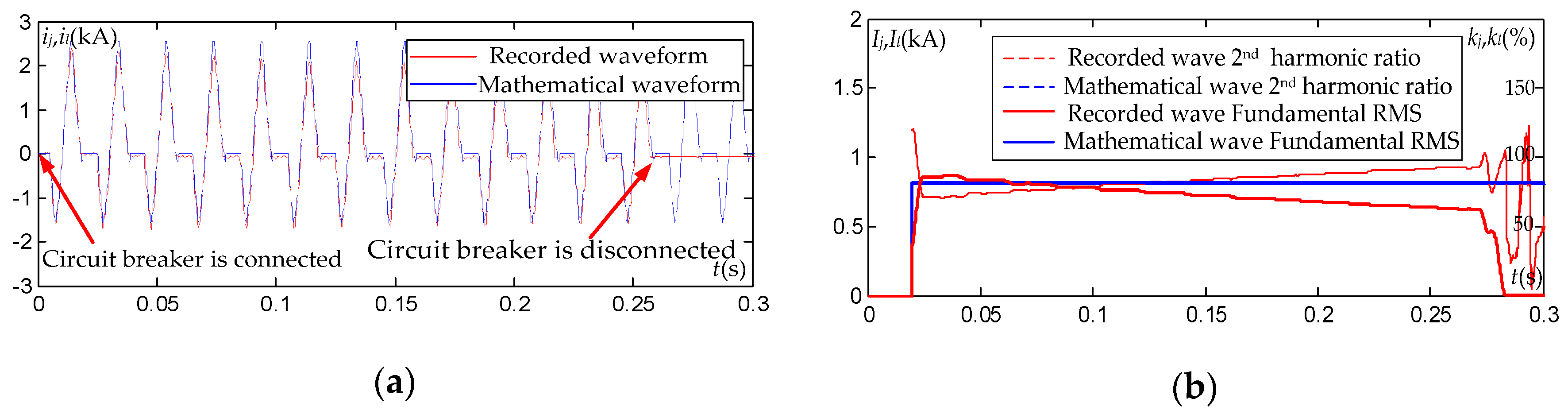
3.2. Comparation of Mathematical Waveforms and Recorded Waveforms

In a recently built 220 kV substation, and the main transformers are T-Hin (SSZ11-240 MVA/220 kV). Ten energizations are performed. The zero-sequence overcurrent protection misoperation occurs in eight times of them. The waveforms of zero-mode inrush current have different and irregular shapes. Three zero-mode inrush current waveforms are selected. Among them, the first one is normal, which the protection has not misoperated. The second one and the third one represent the misoperation of bus connection switch zero-sequence overcurrent protection zone-I and zone-II respectively (zero-sequence protection zone-I is set to 600 A with 0.2 s time delay. zero-sequence protection zone-II is set to 240 A with 0.5 s time delay). In this section, three waveforms will be represented in graphic form by mathematical expression.

3.2.1. Parameter Determination for Mathematical Expression

BJ(t) is determined by Equations (18)–(20). According to the zero-mode inrush current mathematical expression, for a certain transformer, whenever it is energized, the saturated mutual inductance Mair, the high-voltage side self-leakage inductance Lσ, the low-voltage side self-leakage inductance LσD, the system zero-sequence inductance Ls0, system voltage Us and the corresponding magnetic density Bs are fixed values. Ls0 is 0.03 pu in the large mode; Lσ is 0.14 pu; LσD is 0.22 pu; Mair is 0.07 pu; Us is 179.6 kV. For remanence, there are two categories mainly considered in power systems [24]. The first type is the remanence generated by the circuit breaker opening. Due to the symmetry of the three-phase voltage of the power system, the sum of the three-phase remanence of the iron core is zero, which is called “three-phase balanced remanence”. The second type is the core remanence caused by DC resistance test or DC bias, etc. This type of remanence has the same direction and is called “three-phase unbalanced remanence”. According to the background, the remanence is generated by multiple opening of circuit breaker, so only the first type remanence should be considered. In terms of the classical ferromagnetic domain theory and experimental tests [25,26], when the circuit breaker is suddenly open, the three-phase core remanence of the transformer will not maintain the current value, but will instantly decrease and slowly decay to a new steady state. In this paper, the remanence coefficient is Kr = 0.8, and the three-phase remanence density is determined by the following equation:
B r A = K r B S a t cos θ B r B = K r B S a t cos ( θ 120 ° ) B r C = K r B S a t cos ( θ + 120 ° ) }
The saturation magnetic density BSat is considered to be working magnetic density. The saturation magnetic density BSat and the system magnetic density Bs are both 1.7 T. θ is the angle at which the transformer was disconnected last time. We call θ the “opening angle”. According to Equation (23), the last opening angle could be used to represent the core remanence state. Because three phases are almost symmetrical, consider the sum of the three-phase remanence in Equation (17) is zero, namely:
A C B r = 0
According to Equations (23) and (24), Equation (17) can be simplified:
3 i 0 ( t ) = k A C B J ( t ) = f ( α , θ ) ( t )
According to Equation (25), the last opening angle θ and the closing angle α are the determinants of the zero-mode inrush current waveform. The zero-mode inrush current waveform varies with the combination (θ, α). They can be obtained by observing the voltage recorded waveform.

3.2.2. The Graphical Representation

Based on mathematical fitting, the three zero-mode inrush current waveforms are represented graphs, as shown in Figure 4a, Figure 5a and Figure 6a. The angle combinations (θ, α) of the waveforms are (249°, 252°), (341°, 65°) and (250°, 167°) respectively. All the angles refer to the sinusoidal angle of the A-phase voltage. The purpose of our work is to identify the inrush current by using the zero-mode inrush waveform characteristics of the first few cycles. So the attenuation is not considered in the graphical representation of zero-mode inrush current waveform.
“Mathematical waveform” in above figure means the graphical representation of current waves based on the mathematical expression. Ij represents the fundamental RMS value of the mathematical waveform. Il represents the fundamental RMS value of the recorded waveform. kj represents the second harmonic ratio of the mathematical waveform. kl represents the second harmonic ratio of the recorded waveform. The waveform Number One does not have a protection misoperation. The waveform Number Two shows a zero-sequence zone-I misoperation of the bus connection switch, and the circuit breaker is open at 0.26 s after the operating criterion is satisfied. The waveform Number Three shows a zero-sequence zone-II misoperation of the bus connection switch, and the circuit breaker is open at 0.56 s, which did not appear in the picture.
As shown in Figure 4a, Figure 5a and Figure 6a, the mathematical expression can almost completely reconstruct the waveforms, which verify the correctness of the mathematical expression. Because of the randomness of remanence and closing angle, the magnitude of the zero-mode current is also random. For the fundamental RMS value (Ij, Il), the fundamental wave of the waveform Number One is about 100 A, which is very small and the zero-sequence overcurrent protection did not operate. But the fundamental wave of the waveform Number Two is large, and the initial value can reach 800 A. After 0.2 s, it is still larger than the zero-sequence zone-I setting value 600 A. So the protection misoperated. The fundamental wave of the waveform Number Three is smaller than the waveform 2. But the zero-sequence zone-II operating condition (240 A, 0.5 s) is satisfied, so it misoperated. In addition, we found that the second harmonic ratio (kj, kl) of the zero-mode current is high, which is an important waveform characteristic.

4. Improved Method for Zero-Sequence Overcurrent Protection Based on Second Harmonic Ratio of Zero-Mode Inrush Current

According to the above mathematical analysis and recorded waveforms, it is found that the second harmonic ratio of the zero-mode inrush current is high, which may be used as a characteristic to identify the zero-mode inrush current. However, only three sets of recorded waveforms cannot represent all conditions. It is necessary to theoretically demonstrate the second harmonic ratio of the zero-mode inrush current, and obtain the distribution of the second harmonic ratio under various conditions. Based on the mathematical analysis above, the second harmonic ratio is studied as follows.

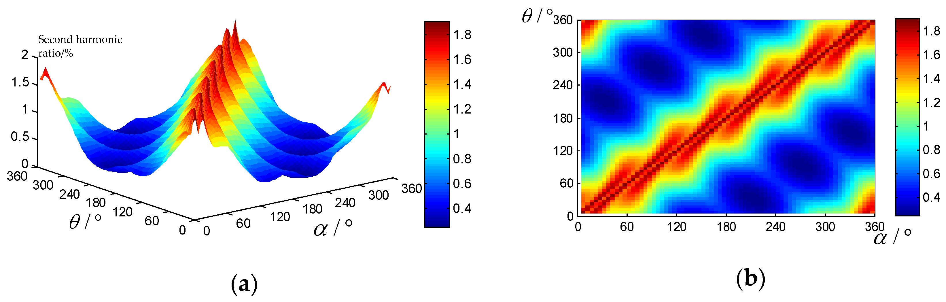
4.1. Distribution of Second Harmonic Ratio

The remanence of the on-site transformer is generated when the circuit breaker opens, so it can be considered as symmetrical remanence. But the transformer may encounter various conditions during the system operation and maintenance. So the following analysis is divided into No remanence, Symmetric remanence and Random remanence in the three-phase iron core.

4.1.1. No Remanence in the Three-Phase Iron Core

Figure 7 is the distribution of the second harmonic ratio with the closing angle under the condition that the three-phase remanence is zero. It can be found that the second harmonic ratio of the zero-mode inrush current is high.

4.1.2. Symmetric Remanence in the Three-Phase Core

Symmetric remanence in the three-phase core is related to the opening angle. According to the numerical calculation of Equation (17), the opening angle and closing angle are selected from 0° to 360° (interval 1°), and the relationship between the second harmonic ratio of the zero-mode inrush current and the opening angle and closing angle is obtained, as shown in Figure 8.
As shown in Figure 8, the minimum second harmonic ratio of the zero-mode inrush current is about 0.25 under the premise of symmetry remanence, and the minimum value always appears at the angle combination of (330°, 150°), (270°, 90°), (210°, 30°), (150°, 330°), (90°, 270°), (30°, 210°), which is called “feature combinations” in this paper. The features of these combinations are:
(1)
The angle difference between opening angle and closing angle are 180°, that is, the relative closing angle is 180°, and the remanence and bias directions of each phase are opposite;
(2)
There is always one phase whose remanence and bias are both zero. For example, in the combination of (330°, 150°), the remanence and bias of phase C are zero; in the combination of (270°, 90°), the remanence and bias of phase A are zero; in the combination of (210°, 30°), the remanence and bias of phase B are zero.

4.1.3. Random Remanence in Three-Phase Iron Core

In actual cases, the magnitude and direction of the three-phase remanence may be random. Therefore, we simulated 1000 sets of random remanences, and the three-phase remanence of each group is a random numerical value in the interval of (−0.7, 0.7), and the phases are independent of each other. Figure 9 shows the relationship between the second harmonic ratio and the closing angle of 1000 sets of three-phase random remanence. It can be found that the second harmonic ratio can be very large, and the minimum value is 0.254, which indicates that the minimum value obtained in the symmetry remanence is the global minimum.

4.2. Improved Criteria

According to the above mathematical analysis, the second harmonic ratio of the zero-mode inrush current is high, and the minimum value is about 25%. When a fault occurs, the zero-mode current is similar to the sinusoidal waveform, whose second harmonic ratio is very low [27,28,29]. Single-phase grounding and two-phase grounding internal faults are simulated in PSCAD V4.6, and the simulated waveforms are shown in Figure 10. In the figure, from top to bottom, there are three-phase currents, zero-mode current with its fundamental RMS, second harmonic ratio. It can be seen that the zero-mode current is very close to the sinusoidal waveform. Although the fundamental RMS is large, the second harmonic ratio is small after one cycle of the fault. Therefore, the second harmonic ratio can be used to distinguish between fault current and zero-mode inrush current. The criteria based on second harmonic ratio will not refuse to operate when the internal fault occurs.
According to the above analysis, the second harmonic is set to 0.25. On the other hand, taking the nonlinearity and hysteresis effect of actual core magnetizing curve into account, the second harmonic ratio of zero-mode inrush current may be higher. Therefore, the restraint criterion is as follows:
I 2 n d % > K 2 x b
Where, I2nd% is the second harmonic ratio in the zero-mode inrush current, and K2xb is the theoretical setting value of the proposed criterion, which is 0.25. The specific operational behavior of criterion is that when the zero-sequence current reaches the setting value, the second harmonic ratio is judged automatically. If the second harmonic ratio exceeds the setting value, it is considered that the inrush current is generated and sends a signal to restrain the protection. Otherwise, it is regarded as a fault current and the protection device operates normally.

4.3. Setting Method in Engineering Application

The minimum value of the second harmonic ratio of the zero-mode inrush current is about 0.25. Considering the nonlinear difference of different transformer cores and other factors in actual operation, the minimum value of the second harmonic ratio of the zero-mode inrush current for a particular transformer in a specific environment may be larger than 0.25, or may be smaller than 0.25. Therefore, it is necessary to adjust according to the actual situation. If the actual ratio is larger than 0.25, the setting value should be increased to improve the reliability of protection. If it is smaller than 0.25, the setting should be reduced to prevent misoperation. According to the previous analysis, the minimum value of the second harmonic ratio is obtained under the “feature combinations” when the symmetry remanence in three-phase cores. The relative closing angle of the feature combinations is 180°, and the remanence and bias of a certain phase are both zero. Therefore, the setting value can be set according to the second harmonic ratio of the zero-mode inrush current under the “feature combinations”. Specifically, the operation is as shown in Figure 11.

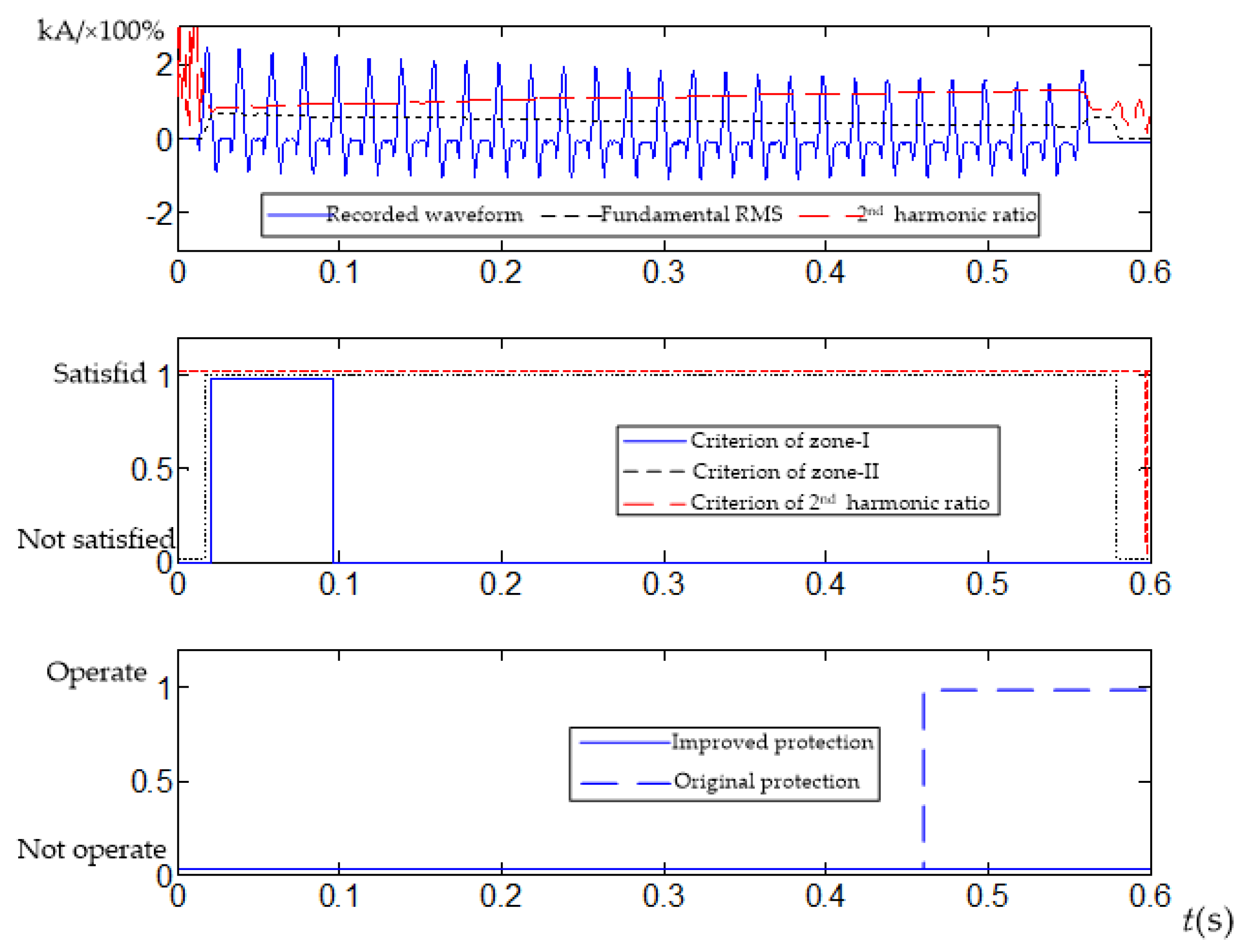
5. Application of the Improved Method

The on-site recorded waveforms are used to verify this method. The three sets of recorded waveforms mentioned above are still selected for testing the operations of the zero-sequence overcurrent protection zone-I and zone-II, as shown in Figure 12, Figure 13 and Figure 14.
As shown in Figure 12, Figure 13 and Figure 14, the protection operation of the original protection is:
(1)
The recorded waveform Number One did not satisfy the setting value of zero-sequence overcurrent protection zone-I and zone-II, and the protection did not operate;
(2)
The recorded waveform Number Two satisfied the setting value of zero-sequence overcurrent protection zone-I and zone-II, and the protection misoperated when reaching the delay of the zone-I;
(3)
The recorded waveform Number Three satisfied the setting value of zero-sequence overcurrent protection zone-I and zone-II, but does not satisfy the delay of zone-I. The protection misoperated when reaching the delay of the zone-II;
The analysis of the three sets of recorded waveforms is consistent with the actual situation. As for the improved protection, because of the reliable restraint of the improved criterion, the three recorded waveforms caused by transformer energizations have not caused protection misoperation. The improved protection retains the functionality of backup protection, with a wider protection range than differential protection. Compared to original zero-sequence overcurrent protection, the improved protection will not misoperate in the case of inrush current. Therefore, the improved method proposed is effective.

6. Conclusions

In order to analyse the mechanism of the larger zero-mode inrush current and propose a method to avoid misoperation, the work carried out in this paper is summarized as follows:
(1)
Based on the derivation of single-phase and three-phase magnetizing inrush current, the mathematical expression of the zero-mode inrush current of transformer is derived;
(2)
According to the mathematical expression and parameter differences between the T-Hin and T-Ord, the zero-mode inrush current of T-Hin is larger, which tends to cause the misoperation of zero-sequence overcurrent protection;
(3)
The zero-mode inrush current recorded waveforms are reconstructed through mathematical expression and it is found that their second harmonic ratio is high, which is verified by mathematical analysis under various conditions;
(4)
An identification method based on the second harmonic ratio of zero-mode inrush current is proposed. Then the theoretical setting value of the method and the practical engineering method for determining the setting value are obtained.
The proposed criterion is applied in the recorded current waveforms. The tests show that the improved protection will not misoperate. Therefore, the improved protection based on the second harmonic ratio restraint is effective and reliable.

Author Contributions

Conceptualization, W.C. and X.Y.(Xianggen Yin); Data curation, Y.C. and Y.W.; Formal analysis, W.C. and Y.P.; Funding acquisition, Y.W.; Investigation, X.Y.(Xiangyuan Yin); Methodology, W.C.; Project administration, X.Y.(Xianggen Yin); Resources, Y.W.; Software, Y.P.; Supervision, X.Y.(Xianggen Yin); Validation, X.Y.(Xiangyuan Yin); Visualization, Y.C. and Y.P.; Writing—original draft, W.C. and Y.C.; Writing—review & editing, Y.C.

Funding

This research was funded by the National Key Research and Development Plan of China grant number 2016YFB0900600 and Guangdong Power Grid Science & Technology Project grant number GDKJXM20162461.

Conflicts of Interest

The authors declare no conflict of interest.

Appendix A

Figure A1. Recorded waveform Number One (0–3.4 s).
Energies 12 02911 g0a1
Figure A2. Recorded waveform No. 1 (0–0.6 s).
Energies 12 02911 g0a2
Figure A3. Recorded waveform No. 2 (0 s–0.6 s).
Energies 12 02911 g0a3
Figure A4. Recorded waveform No. 3 (0 s–0.6 s).
Energies 12 02911 g0a4
Figure A5. Recorded waveform No. 4 (0 s–0.6 s).
Energies 12 02911 g0a5

Appendix B

Explanation of terms in Figure 1 and Figure 2.
The electrical quantity in the Figure has been calculated to the primary winding side.
Hmagnetic field intensity.
Bmagnetic density
μ0permeability of vacuum
ψflux linkage
Wthe number of winding turns
Sthe cross-sectional area
JSatthe saturation magnetization
uA, uB, uCthree-phase voltage of the system
Lspositive-sequence inductance
Ls0zero-sequence inductance
Lσleakage inductance of primary winding
LσDleakage inductance of secondary winding
ea, eb, ecinduced electromotive force
iDcirculation current of delta winding
Mairsaturated mutual inductance

References

  1. Sharp, R.L.; Glassburn, W.E. A Transformer Differential Relay with Second-Harmonic Restraint. IEEE Trans. Power Appar. Syst. 1958, 3, 913–918. [Google Scholar] [CrossRef]
  2. Hayward, C.D. Prolonged inrush currents with parallel transformers affect differential relaying. Electr. Eng. 1941, 12, 1096–1101. [Google Scholar] [CrossRef]
  3. Bi, D.Q.; Wang, X.H.; Li, D.J.; Yu, G.W.; Wang, Z.J.; Wang, W.J. Theory Analysis of the Sympathetic Inrush in Operating Transformers. Autom. Electr. Power Syst. 2005, 6, 1–8. [Google Scholar]
  4. Zhang, A.Q.; Ji, T.Y.; Li, M.S.; Wu, Q.H.; Zhang, L.L. An Identification Method Based on Mathematical Morphology for Sympathetic Inrush. IEEE Trans. Power Deliv. 2018, 1, 12–21. [Google Scholar] [CrossRef]
  5. Qi, X.W.; Yin, X.G.; Zhang, Z.; Chen, D.; Wang, Y.; Cai, F. Study on the Unusual Misoperation of Differential Protection During Transformer Energization and its Countermeasure. IEEE Trans. Power Deliv. 2016, 5, 1998–2007. [Google Scholar] [CrossRef]
  6. Peng, F.; Gao, H.L.; Liu, Y.Q. Transformer Sympathetic Inrush Characteristics and Identification based on Substation–Area Information. IEEE Trans. Power Deliv. 2018, 1, 218–228. [Google Scholar] [CrossRef]
  7. Brunke, J.H.; Frohlich, K.J. Elimination of Transformer Inrush Currents by Controlled Switching–Part I: Theoretical Considerations. IEEE Trans. Power Deliv. 2001, 2, 276–280. [Google Scholar] [CrossRef]
  8. Brunke, J.H.; Frohlich, K.J. Elimination of Transformer Inrush Currents by Controlled Switching–Part II: Application and Performance Considerations. IEEE Trans. Power Deliv. 2001, 2, 281–285. [Google Scholar] [CrossRef]
  9. Liu, J.; Hao, X.D.; Wang, X.; Chen, Y.F.; Fang, W.L.; Niu, S.B. Application of thyristor controlled phase shifting transformer excitation impedance switching control to suppress short-circuit fault current level. J. Mod. Power Syst. Clean Energy 2018, 4, 821–832. [Google Scholar] [CrossRef]
  10. Li, Y.; Su, Z.H.; Wang, R.F.; Xu, Z.F.; Lin, Y.T.; Zhan, X.B. Calculation and Analysis of Magnetizing Inrush Current of High Impedance Transformer with Built-In High Voltage Winding. Transformer 2017, 8, 1–5. [Google Scholar]
  11. Li, X.H.; Luo, L.L.; Xie, J.Q.; Li, Y.Q.; Li, Y. Impact of Inrush Current Characteristics of High-Voltage Built-in High-impedance Transformer on Relay. Autom. Electr. Power Syst. 2016, 11, 108–114. [Google Scholar]
  12. Li, C.; Li, B.; Guo, F.; Geng, J.; Zhang, X.; Coombs, T. Studies on the active SISFCL and its impact on the distance protection of the EHV transmission line. Prot. Control Mod. Power Syst. 2016, 1, 1–18. [Google Scholar] [CrossRef]
  13. Xu, C.H. Analysis of the zero-sequence Inrush Current Waveform for 500kV Transformer. Relay 1983, 3, 13–21. [Google Scholar]
  14. Tan, J.; Xiao, H.; Li, Y.; Zhang, A.L.; Li, Y.H. Study on impact of transformer magnetizing inrush current on the line zero sequence overcurrent protection by transient simulation. Power Syst. Prot. Control 2015, 19, 149–153. [Google Scholar]
  15. Du, J.W.; Liu, S.Z.; Wang, B. Study on Principle of Zero-Sequence Component Caused by transformer Inrush Phenomenon. Electr. Appl. 2007, 1, 27–31. [Google Scholar]
  16. Du, J.W.; Zhang, J.T.; Peng, H. Analysis of Impact of Transformer and Inrush Current on Zero-sequence Protection. Electr. Appl. 2009, 1, 42–46. [Google Scholar]
  17. Fang, Y.D.; Xu, X.D.; Zhu, B.Q. Impact of transformer inrush on zero-sequence current protection. Electr. Power Autom. Equip. 2008, 9, 115–118. [Google Scholar]
  18. Guo, Q.W.; Mo, W.X.; Zheng, F.Q.; Xiong, J. Analysis and measures of zero sequence current protection malfunction caused by no-load high-voltage built-in transformer. Power Syst. Prot. Control 2018, 22, 164–170. [Google Scholar]
  19. Weng, H.L.; Liu, W.; Lin, X.N.; Jin, N.; Li, Z.X.; Huang, J.G. Mechanism and Countermeasures of Mal-operation of Converter Transformer Zero-sequence Overcurrent Protection Caused by Inrush Currents. Autom. Electr. Power Syst. 2019, 9, 171–182. [Google Scholar]
  20. Wang, Y.X.; Cao, W.B.; Huang, M.H.; Yin, X.G.; Zeng, G.H.; Li, Y.Q.; Liu, W.; Chen, Q.P.; Wang, Z.C.; Liu, K. Mathematical Analysis for Zero-Mode Inrush Current of Transformer and Its Equivalent Circuit. Power Syst. Technol. 2018, 12, 3960–3968. [Google Scholar]
  21. Suonan, J.L.; Jiao, Z.B.; Kang, X.N.; Zhang, Y.N.; Song, G.B.; Liu, K. Algorithm to Identify Leakage Inductances of Power Transformer With Y-Delta Connection. Proc. CSEE 2008, 13, 84–90. [Google Scholar]
  22. Shi, S.W. Large Generator and Transformer Relay Protection; China WaterPower Pressfigure: Beijing, China, 1987. [Google Scholar]
  23. Yin, X.G.; Cao, W.B.; Pan, Y.L.; Wang, Y.X.; Guo, Q.; Liu, W. Inrush current characteristic of high-impedance transformers and its impact on protective relays. Power Syst. Prot. Control 2018, 20, 1–11. [Google Scholar]
  24. Jiao, Z.B.; Xing, W.; Wang, Z.; Jin, J.L. Features and Mechanism of Negative-sequence Second Harmonics of Magnetizing Inrush Current in Transformers. Autom. Electr. Power Syst. 2015, 11, 146–151. [Google Scholar]
  25. Jia, N.; Ma, S.M.; Li, Z.D.; Chen, Y.W.; Mao, J.; Zhou, L. Research on Initial Remanence Coefficient and Stable Remanence Coefficient of Current Transformer. Water Res. Power 2017, 11, 194–197. [Google Scholar]
  26. Qian, K.M.; Dai, D.S. Ferromagnetics; Science Press: Beijing, China, 1998. [Google Scholar]
  27. Shao, W.Q.; Qiao, N.; Wang, J.B. A novel algorithm of identifying inrush current based on waveform cross-correlation coefficient. Power Syst. Prot. Control 2015, 23, 14–20. [Google Scholar]
  28. He, J.H.; Li, J.Z.; Yao, B.; Ou, Z.J.; Fan, Y. A New Approach of Transformer Inrush Detected Based on the Sine Degree Principle of Current Waveforms. Proc. CSEE 2007, 4, 54–59. [Google Scholar]
  29. Bi, D.Q.; Zhang, X.A.; Yang, H.H.; Yu, G.W.; Wang, X.H.; Wang, W.J. Correlation Analysis of Waveforms in Nonsaturation Zone-Based Method to Identify the Magnetizing Inrush in Transformer. IEEE Trans. Power Deliv. 2007, 3, 1380–1385. [Google Scholar] [CrossRef]
Figure 1. Magnetizing characteristic curve.
Energies 12 02911 g001
Figure 2. Y0/Δ three-phase transformer magnetizing inrush current equivalent circuit.
Energies 12 02911 g002
Figure 3. Three-phase magnetic density schematic diagram.
Energies 12 02911 g003
Figure 4. Graphical representation for waveform Number One: (a) original waveform; (b) fundamental RMS and second harmonic ratio.
Energies 12 02911 g004
Figure 5. Graphical representation for waveform Number Two: (a) original waveform; (b) fundamental RMS and second harmonic ratio.
Energies 12 02911 g005
Figure 6. Graphical representation for waveform Number Three: (a) original waveform; (b) fundamental RMS and second harmonic ratio.
Energies 12 02911 g006
Figure 7. The distribution of the second harmonic ratio with the closing angle when the three-phase remanence is zero.
Energies 12 02911 g007
Figure 8. The distribution of the second harmonic ratio with the opening and closing angle: (a) front view; (b) top view.
Energies 12 02911 g008
Figure 9. Relationship between second harmonic ratio and closing angle under random remanences.
Energies 12 02911 g009
Figure 10. Fault current and its second harmonic ratio: (a) single-phase grounding; (b) two-phase grounding.
Energies 12 02911 g010
Figure 11. The operation of setting method in engineering application.
Energies 12 02911 g011
Figure 12. Protection behavior of waveform Number One.
Energies 12 02911 g012
Figure 13. Protection behavior of waveform Number Two1.
Energies 12 02911 g013
Figure 14. Protection behavior of waveform Number Three.
Energies 12 02911 g014
Table 1. The comparison of the three parameters.
ParametersLσLσDMair
T-Hin0.14 pu0.22 pu0.07 pu
T-Ord0.14 pu0.09 pu0.2 pu

