Control Technology of Soft Rock Floor in Mining Roadway with Coal Pillar Protection: A case study

1
School of Energy Science and Engineering, Henan Polytechnic University, Jiaozuo 454000, China
2
Collaborative Innovation Center of Coal Work Safety, Henan Polytechnic University, Jiaozuo 454000, China
3
Technology Center of Sichuan Province Coal Industry Group, Chengdu 610091, China
4
Sichuan Hua Ying Shan Longtan Coal and Electricity Co., LTD., Guangan 638020, China
*
Author to whom correspondence should be addressed.
Energies 2019, 12(15), 3009; https://doi.org/10.3390/en12153009
Submission received: 6 July 2019
/
Revised: 31 July 2019
/
Accepted: 2 August 2019
/
Published: 4 August 2019
Abstract
:This study considered the mining roadway with coal pillar protection in the fully mechanized caving face of the Dananhu No.1 Coal Mine, China. Theoretical analysis, numerical simulation, and field tests were conducted, and the stress environment, deformation, and failure characteristics of the mining roadway in the fully mechanized caving face were analyzed. The results revealed that the intrinsic cause for the large asymmetrical floor deformation in the mining roadway is the asymmetrical phenomenon of the surrounding rock’s stress environment, caused by mining. This also results in the non-uniform distribution of the mining roadway floor’s plastic zone. The degree of asymmetrical floor heave is internally related to the thickness of the caving coal. When the thickness of the caving coal was in the range of 5.9 m, the deformation of the asymmetrical floor heave, caused by the plastic failure in the floor, became more obvious as certain parameters increased. As the rotation angle of the principal stress direction increased, the maximum plastic failure depth position of the floor gradually moved toward the middle of the roadway. This caused a different distribution for the maximum deformation position. The control of the floor heave deformation was poor, and it was not feasible to use high-strength support under the existing engineering conditions. Hence, the control should mainly be applied to the floor heave deformation. When the thickness of the caving coal was more than 5.9 m, the main roof strata was prone to instability and being cut along the edge of the coal pillar; the rock stress environment surrounding the roadway tended to revert back to the initial geostress state. The proposed floor heave control strategy achieved good results, and as the deformation of the floor heave decreased, the workload of the floor heave was also greatly reduced.
1. Introduction
Setting the section coal pillar in a fully mechanized caving face is the conventional method for maintaining the stability of rock surrounding an underground mining roadway. The mining roadway in a fully mechanized caving face is affected by the active mining process, such that the surrounding rock is generally in a non-uniform stress environment, which causes the asymmetric distribution of deformation and the failure of the rock surrounding the roadway. When the roadway floor is weak or the size of the coal pillar is unreasonable, a strong asymmetric floor heave results in the roadway. This causes the shrinking of the roadway section, and the obstruction of transportation and human walking, and can even cause the scrapping of the entire roadway [1,2]. For a fully mechanized caving face, the different thicknesses of the caving coal correspond to different main roof strata activity states. The non-uniform characteristics of the stress around the rock surrounding the roadway are inconsistent, and the distribution law of the floor heave deformation is more complex [3,4,5,6,7]. To clarify the mechanism and law governing the asymmetric floor heave of the mining roadway in a fully mechanized caving face, we propose a targeted response plan to ensure the normal operation and safety of the roadway.
The floor heave control of mining roadways has always been an important issue in the field of mine pressure and rock mechanics. In recent years, many studies have been conducted to clarify the deformation mechanism of the roadway floor heave, and countermeasures have been proposed to control it. To date, different types of roadway floor heave management methods have been proposed. Hou et al. [8,9,10] reported that the main factor influencing the floor heave of the mining roadway is the front abutment pressure of the coal face. The floor heave of the mining roadway is mainly caused by the post-peak deformation of the floor’s broken strata. The deformation of the roof and two sides of the roadway also exert a significant influence on the floor heave. Reinforcing the two sides of the roadway and the corners can achieve better control over the floor heave of the mining roadway. He et al. [11,12,13] proposed a new method to effectively control the floor heave by considering the interaction of the three parts of the surrounding rock (roof, two sides, and floor). Kang et al. [14,15,16,17,18] analyzed the influence of mining and side pressure coefficient on the roadway floor heave. The relationship between the thickness of the soft rock stratum and the mechanical properties of the surrounding rock and floor heave were analyzed. Bai et al. [19,20] analyzed the deformation and failure characteristics of the mining roadway’s floor, and elucidated the floor heave mechanisms of shallow bulging and deep sinking. Moreover, the displacement law of the floor rock at different depths was further analyzed, and the characteristics of “two dots and three areas” of the floor heave were determined. Based on the analysis of the deformation characteristics of the rock surrounding a deep roadway, the reinforcement mechanism for the continuous double shell of a deep roadway was reported by Yang et al. [21,22,23]. The double-shell reinforcement mechanism was analyzed, and the floor heave control for the middle and deep reinforcement of the thick coal seam roadway was proposed. Recently, Ma et al. [24,25,26,27,28,29,30,31] proposed the butterfly plastic zone theory for rock surrounding boreholes and roadways, based on a large number of practical engineering projects. This theory fully considers the influence of the stress direction around the rock surrounding the roadway, the principal stress difference, the principal stress ratio, and other factors closely related to the mining influence on the deformation and failure of the rock surrounding a roadway. It is believed that the shape and extent of the plastic zone determine the extent of damage to the rock surrounding the roadway.
Affected by the geological conditions of the mine, the production capacity and the relationship between mining and tunneling, the service life of the roadway is determined. Generally, the service life of a mining roadway is less than two years. The deformation control of the floor heave should not adopt high-strength, multi-layer control, joint support, or other approaches. Instead, pertinent control ideas are required. Based on the results of previous researchers, the plastic zone distribution in the floor of a mining roadway in a fully mechanized caving face was taken as the main clue. The authors systematically investigated the stress environmental characteristics and the deformation and failure mechanism of the rock surrounding the mining roadway in the fully mechanized caving face. A method for controlling the floor heave of the mining roadway is proposed to provide a theoretical foundation and an effective approach toward controlling the stability of the rock surrounding the roadway floor.
2. Deformation Characteristics and Stress Environment Analysis of Rock Surrounding Roadway
2.1. Structural Characteristics of Rock Surrounding Roadway
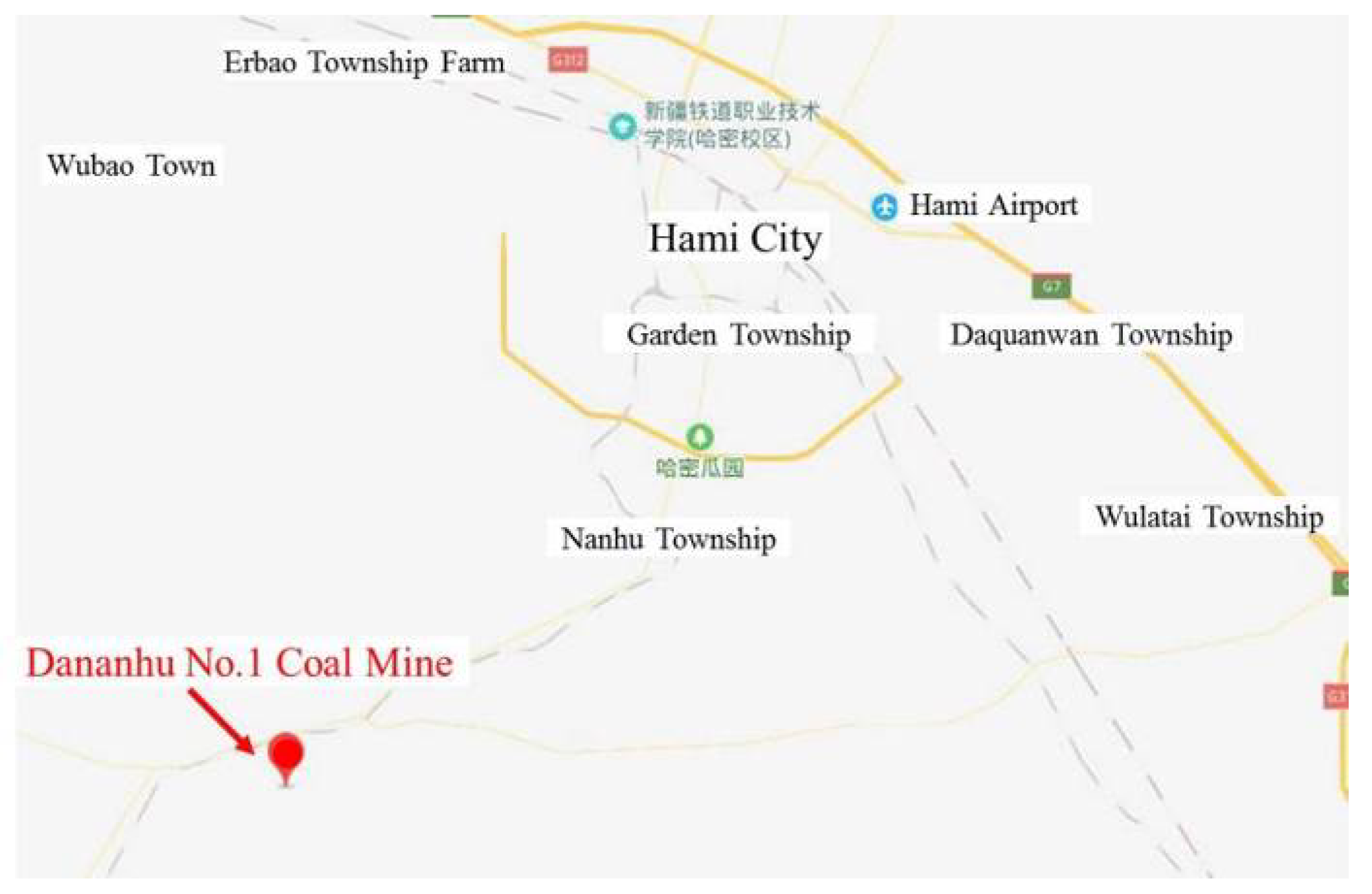
The Dananhu No. 1 Coal Mine is located in Hami City, Xinjiang, China. The location map for the Dananhu No.1 Coal Mine is presented in Figure 1. At present, the #3 coal seam is mined, and the coal seam dip angle is 3–13°. The thickness of the coal seam varies greatly, mostly within the range of 5.2–9.5 m, and the average thickness is 5.8 m. The buried depth is approximately 260 m. The panel is caving coal mining, and the mining roadways on both sides are arranged along the coal floor. The #3 coal seam floor of the mine’s panel 1306 area is mainly composed of carbonaceous mudstone, sandy mudstone, and siltstone. Up to approximately 4.0 m, the rock is argillaceous rock with weak strength and sensitivity to the influence of mining. The immediate roof of the #3 coal seam mainly consists of mudstone rock with lower strength. The main roof mainly consists of siltstone with a thickness of more than 15.0 m, and a small part of sandy mudstone. The main roof has better integrity. The roof, coal seam and floor strata structure peephole results for the coal seam of the panel 1306 return airway roadway are presented in Figure 2.
The replacement method for the panel consists of reserving coal pillars to protect the roadway. The presence of an aquifer above the roof of the coal seam results in a large amount of water in the adjacent goaf, and the mine uses thick coal mining. Under such production and geological conditions, it is easy to have the water in the goaf pouring into the coal face. When the coal pillar size is less than 10 m. At the same time, the mine tried to set up coal pillars with a width of 30–35 m, but the phenomenon of floor heave is still significant, due to the soft floor of the roadway and sensitivity to the influence of mining. Considering the severe rich water conditions in the goaf and the rate of resource mining, the coal pillar size was determined as 20 m. To alleviate the intense relationships between mining and tunneling, before panel 1304 was mined, panel 1306’s return airway in the mining roadway had been arranged. This subjected the mining roadway to a drastic mining effect during panel 1304’s mining process. The surrounding rock deformation was severely damaged under the influence of the front abutment pressure and side abutment pressure, which were exerted by the rock surrounding the roadway during the mining process. The mining roadway layout of panels 1304 and 1306 is shown in Figure 3.
During the mining process of panel 1304, the asymmetric deformation of the surrounding rock in the mining roadway was significant. The deformation was mainly based on the floor heave, the floor heave amount reached 1500–2500 mm, and the amount of roof convergence was 300–500 mm. In the area wherein the deformation of the surrounding rock was most severe, the top and bottom of the roadway were in full contact, and the roadway could not be used properly. From the position of the maximum floor heave volume distribution, the maximum deformation of the floor heave was mainly on the side of the coal pillar. Occasionally, deformation appeared in the middle of the roadway and on the solid coal side. According to the mining condition of panel 1304, this asymmetric floor heave phenomenon was greatly correlated with the caving coal thickness of the upper section panel.
2.2. Monitoring of Law Governing Floor Heave in Mining Roadway
During the mining of panel 1304, the phenomenon of the floor heave of the 1306 return airway in the adjacent mining roadway is particularly prominent. To specifically understand the laws governing the deformation of the roadway floor heave during the mining process, surface displacement measuring stations were arranged on the mining roadway, and the distance between the stations was 30 m. Forty-five stations were set up. The first station was 120 m away from the panel 1304 setup entry, and the distance between the stations was 30 m. When the coal face was advanced to 40 m from the front of the station, the measurement work began. When the station was 130 m behind the coal face, the measurement work stopped.
The coal seam thickness is monitored at intervals of 80–100 m in the field. According to the measurement of surface displacement, the asymmetric floor heave phenomenon of the coal pillar roadway is directly related to the coal thickness of the upper section panel, as shown in Figure 4. The setup entry is driven at the starting line of a longwall panel and used to set up equipment, from which mining activities begin. Within a certain range of top coal thickness, the maximum deformation position of the floor gradually moves toward the middle position of the roadway as the thickness of the top coal increases. For example, when the top coal thickness of the upper section panel was 3.8 m, the maximum deformation position of the floor was on the side of the coal pillar. When the top coal thickness increased to 4.7 m, the maximum deformation position of the floor was biased toward the middle. When the thickness of the top coal increased to a certain extent, the maximum deformation position of the floor was still biased toward the middle in most areas. The deformation of the surrounding rock was obviously moderated in the small part of the area. As shown in Figure 4, the thickness of the top coal was 6.3 m and 6.7 m.
From a deformation law viewpoint, the mining roadway is affected by the front abutment pressure and side abutment pressure of the upper section panel, and an asymmetric floor heave phenomenon occurs. During this process, the amount of floor heave sharply increases, and the side abutment pressure is again affected. The influence of the side abutment pressure has a certain hysteretic nature.
2.3. Analysis of Stress Environment of Surrounding Rock in Mining Roadway
The law governing the floor heave of the mining roadway and the mining of the upper section panel indicates that the asymmetric floor heave phenomenon is greatly correlated with the coal mining thickness of the upper section panel. The main reason for the analysis is that the change in the thickness of the coal is caused by the difference in the filling degree of the goaf. Along with the difference in the degree of the main roof strata rotation in the upper section panel, the stress around the surrounding rock of the mining roadway becomes uneven. This uneven stress around the surrounding rock is the intrinsic reason for the occurrence of the asymmetric floor heave phenomenon in the roadway.
The surface connected fissure formed by the goaf of the upper section panel was observed to clarify the main roof strata rotation state of the upper section panel, and the stress characteristics of the rock surrounding the mining roadway. Figure 5 shows the side surface connected fissure of panel 1304. As can be seen, the fissure size is different, which means that the breaking deflection angle of the main roof strata is also different. The existence of the cutting fissure indicates that the breaking of the main roof strata also appeared as cut off. Moreover, a certain relationship exists between the shape of the surface-connected fissure and the top coal thickness of the upper section panel. When the thickness of the top coal is small, the size of the fissure is also small, as shown in Figure 5a. When the thickness of the top coal is large, the size of the fissure is larger. In addition, the fractured fissure may also be cut off, as shown in Figure 5b,c.
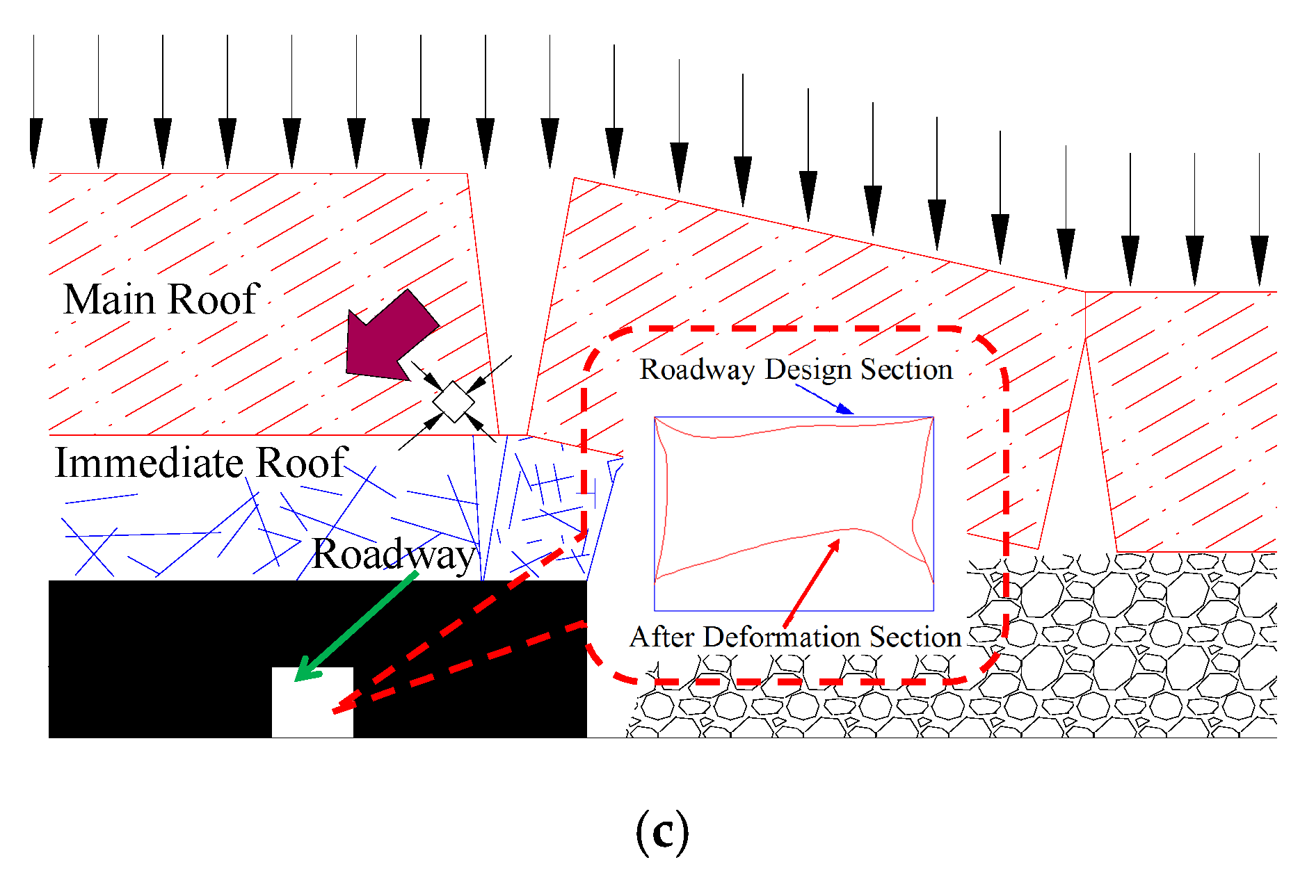
According to the observation and thickness statistics of the top coal during the mining process of the upper section panel, the roof overburden in the area above the mining roadway can be approximately divided into three types: smaller thickness of top coal (below 2 m), medium thickness of top coal (2–5 m), and larger thickness of top coal (more than 5 m). The mining roadway is in the side abutment pressure influence zone, which was formed during the mining of the panel’s upper section. According to the coal caving thickness and the main roof strata movement state of the coal face, the stress environment around the rock surrounding the mining roadway is affected by the side abutment pressure. Figure 6 shows the stress environment of the rock surrounding the mining roadway with different caving coal thicknesses and roadway deformation profiles.
Assume that the immediate roof thickness and its fallen state have not changed, and the filling degree of the goaf is only related to the thickness of the top coal. The filling degree of the goaf is gradually reduced as the thickness of the top coal increases. The difference between the goaf areas is mainly reflected in the difference in the thickness of the top coal. With a smaller top coal thickness (below 2 m), as shown in Figure 6a, the thickness of the caving coal was small during the mining process of the upper section. The surface morphology under these conditions is shown in Figure 5a. Moreover, the filling degree of the goaf was sufficient under the effect of the collapse of the immediate roof strata. After the main roof strata broke, the rock had a smaller angle of rotation. Under these conditions, the abutment pressure concentration occurred at the position of the mining roadway. The direction of the maximum principal stress in the stress of the surrounding rock was also deflected to some extent. As the thickness of the top coal increased, the filling degree of the goaf became poorer, as shown in Figure 6b,c. The surface morphology under these conditions is shown in Figure 5b. After the main roof strata broke, the rock had a larger angle of rotation. However, the breaking of the main roof strata could still maintain the hinge connection. Under this condition, the concentration of the abutment pressure in the mining roadway position further increased, and the maximum principal stress in the surrounding rock stress was also deflected to a large extent.
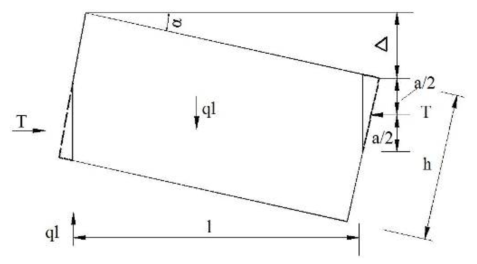
However, the fracture position of the main roof strata was not necessarily above the coal pillar. Different locations of the main roof fractures lead to different surrounding rock stress environments. In a small area, when the thickness of the coal further increased, the degree of rotation of the main roof strata increased further. This caused a local stress concentration at the squeezing point, which initiated a plastic state, and the main roof strata were rotated to a certain extent. If the fracture position of the main roof strata was at the edge of the coal pillar, the entire structure may have been unstable [32]. It will cause the fissure to fracture in the mining process. The state after the rock was rotated and the meaning of the relevant symbols are presented in Figure 7.
Owing to the articulated point being in a plastic state, the point of action of force T was taken at a/2. The value of Δ can be approximated as lsinα, as follows:
The compressive stress that formed at the articulated point is expressed as follows:
The ratio of the bearing strength to the compressive strength [] in the rock block is set to . The value of the allowable load q is expressed as follows:
When the beam breaks (reaches the limit span), the relationship between the load q and the rock beam tensile strength is expressed as follows:
Here, K depends on the state of the beam’s clamped support or simple support, and is generally 1/2 to 1/3.
In the general rock, the ratio of the compressive strength [] to the tensile strength is set to n.
Therefore:
According to the abovementioned analysis, when the maximum sinking amount of the rock block reaches Δ, the entire main roof strata structure is prone to instability, and the cutting of the main roof strata occurs, as shown in Figure 8. When the main roof becomes fractured, it will form a certain structure. This structure is consistent in front of the coal face and in the goaf area. The immediate roof strata fall immediately with the mining process. Therefore, it is inconsistent in front of the coal face and in the goaf area. The immediate roof becomes broken gangue in the goaf area. The surface morphology under these conditions is shown in Figure 5c. In this case, the concentration degree of the abutment pressure in the mining roadway is greatly reduced, and the deflection degree of the maximum principal stress in the surrounding rock stress is correspondingly smaller.
According to the geological conditions of the #3 coal seam in the Dananhu No.1 Coal Mine, the main roof strata thickness h is 11.0 m, n = 8, K = 1/2, and = 1.5. From Equation (9), Δ = 8.4 m. According to the geometric relationship between the coal seam and the roof strata after the coal seam mining, the actual maximum sinking amount Δ0 of the rock block is expressed as follows:
Here, M is the coal seam thickness (m), ∑h is the thickness of the immediate roof (m), and K0 is the rock coefficient of the bulk increase (1.3).
Therefore, when Δ0 > Δ, the main roof strata are prone to instability, and the fractured fissure is cut off. In the Dananhu No.1 Coal Mine, the #3 coal seam thickness of the immediate roof is 2.6 m. From Equations (9) and (10), the limit coal seam thickness causing the instability and fractured of the main roof strata is 9.2 m. By subtracting the height of the roadway (3.3 m), we can obtain the limit thickness of the top coal as 5.9 m.
From the above analysis, it can be seen that a significant difference exists in the stress environment around the rock surrounding the mining roadway in the fully mechanized caving face. After the mining of the upper section of the coal face, the phenomenon was more obvious with different caving coal thicknesses. As the thickness of the coal increased, the fracture angle of the main roof strata also increased. Moreover, the concentration of the abutment pressure increased at the position of the mining roadway, and the deflection degree of the maximum principal stress in the stress of the surrounding rock also increased. When the thickness of the coal exceeded a certain limit, the underlying main roof strata were prone to instability and fractured, and the surrounding force distribution of the roadway rock was essentially restored to the initial geostress state.
3. Numerical Analysis of Roadway’s Floor Heave Mechanism
3.1. Modelling
As is well known, the deformation and failure of the rock surrounding roadways is essentially caused by plastic failure. To clarify the asymmetric floor heave mechanism of the mining roadway in a fully mechanized caving face, FLAC3D numerical simulation software was used to analyze the plastic failure distribution characteristics of the rock surrounding the mining roadway under different stress environments. The analysis results revealed that the difference in the thickness of the caving coal was caused by the difference of the side abutment pressure distribution around the rock surrounding the mining roadway, which caused an uneven principal stress ratio. According to the conventional ground pressure theory, the concentration phenomenon of abutment pressure occurs in the position of coal pillar roadway [32,33]. The stress increase coefficient can reach 2.0–4.0. At the same time, the stress values in other directions will inevitably increase to some extent. Therefore, the principal stress ratio is slightly smaller than the stress increase coefficient. To clarify the general law, the ratio of principal stress is 1.5–3.0. The stress increase coefficient is the ratio of the increased stress to the original stress. The stress distribution around the rock surrounding the mining roadway can be approximately divided into three categories: smaller thickness top coal, medium thickness top coal, and larger thickness top coal. To simplify the simulation process and elucidate the general governing laws, we used the numerical simulation scheme presented in Table 1.
Based on the specific engineering geological conditions of the #3 coal seam of the Dananhu No. 1 Coal Mine (Figure 2), the rock’s physical and mechanical parameters considered in the numerical simulation are presented in Table 2. By combining the different thicknesses of the coal caving conditions, the respective models were established. The overall size of the different models was 48 m × 10 m × 48 m, 48 m × 10 m × 50 m, and 48 m × 10 m × 52 m. The roadway was located at the middle of the model, with a net width and net height of 5.0 m and 3.5 m, respectively. The grid size adjacent to the mining roadway area in the X and Z directions was 0.5 m. In the Y direction, the grid size was 1 m. The model of the top 2 m of the coal included 7008 zones and 14,356 grid points. The model of the top 4 m of the coal included 7392 zones and 15,132 grid points. The model of the top 6 m of the coal included 7776 zones and 15,908 grid points. The numerical model for different caving coal thicknesses is shown in Figure 9. The stress values and directions applied by the model boundary are listed in Table 1 according to the site’s geological conditions. The model limited the displacement and initial velocity in the X direction. At the bottom edge, the model limited the displacement and initial velocity in the three directions of X, Y, and Z. The simulation was conducted using the Moore−Coulomb criterion based on elastoplastic theory.
3.2. Analysis of Numerical Simulation Results
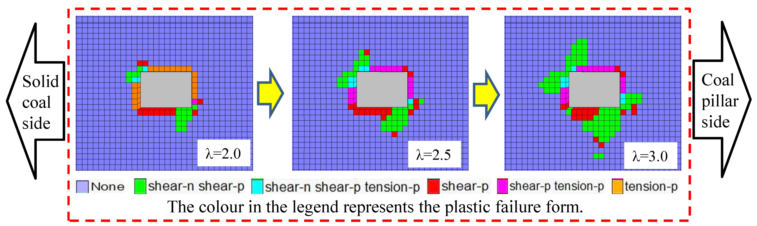
The plastic zone of the rock surrounding the roadway exhibited non-uniform expansion as the absolute value of the principal stress and the principal stress ratio increased. When the top coal was 2 m, the simulation result of the roadway’s plastic zone distribution under different stress environments is shown in Figure 10. When the principal stress ratio was 1.5, the plastic failure of the rock surrounding the roadway mainly occurred at the top and bottom of the roadway. The maximum damage range was located on the side of the coal pillar and the damage depth was 1.0 m. When the principal stress ratio was 2.0, the plastic failure began to expand to the solid coal side and coal pillar side of the roadway. The surrounding rock had asymmetrical damage. The maximum damage range of the surrounding rock was also located at the coal pillar side, and the damage depth was 2.0 m. When the principal stress ratio was 2.5, the plastic failure range significantly increased. Particularly in the roadway floor area, the asymmetric characteristics of the plastic failure distribution were more significant, and the maximum damage depth was 2.5 m.
Figure 11 shows the simulation results for the plastic zone distribution of the roadway under different stress environments when the top coal was 4 m. When the principal stress ratio changed from 2.0 to 3.0, the range of plastic damage significantly increased. The maximum damage depth position moved to the middle position of the roadway. Under the condition of the principal stress ratio of the same rock surrounding the roadway, the principal stress deflection angle increased, and the range of the damage area increased accordingly. Moreover, by comparing Figure 10 and Figure 11, it was found that the maximum plastic damage depth position of the floor gradually moved toward the roadway’s middle position. The principal stress direction’s angle of rotation also gradually increased, and this was the intrinsic reason for the different position distribution of the mining roadway’s floor heave deformation.
When the principal stress ratio was 3.0 and the principal stress direction was rotated by 45°, the maximum damage depth was 3.5 m and occurred close to the side of the coal pillar. This corresponded to the statistical results of the floor heave deformation of the mining roadway, as shown in Figure 4. The plastic failure depth of the surrounding rock and the floor heave deformation were the largest. Figure 12 shows the comparison of field photos of the mining roadway, and the numerical simulation results of the surrounding rock deformation profile.
When the top coal exceeded a certain thickness, the field observations revealed that the deformation and destruction of the rock surrounding the roadway improved. Figure 13 shows the simulation results for the plastic zone distribution of the roadway under different principal stress environments with the top coal at 6 m. Owing to the instability and fractured of the overlying basic top rock stratum, the principal stress ratio and the rotation angle around the roadway were greatly reduced. The plastic failure range of the rock surrounding the roadway was also significantly reduced. Moreover, the deformation of the floor heave was significantly reduced.
Combining Statistical results of floor heave law and thickness of caving coal (Figure 4) and numerical simulation results, the parameters in accordance with the actual project are determined. When the thickness of the top coal is about 2 m, the ratio of principal stress is 2.0, and the direction of principal stress is 30°. When the thickness of the top coal is about 4m, the ratio of principal stress is 3.0, and the direction of principal stress is 45°. When the thickness of the top coal is about 6m, the ratio of principal stress is 1.5, and the direction of principal stress is 10°.
3.3. Theoretical Analysis of Mining Roadway’s Floor Heave Mechanism
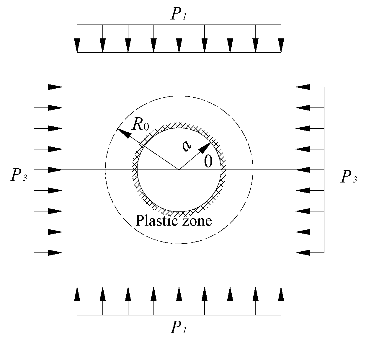
The variation of the principal stress ratio and the rotation angle around the roadway causes the difference in the distribution of the floor heave’s deepest position. The variation of the principal stress ratio determines the plastic failure depth of surrounding rock. The variation of the principal stress rotation angle determines the deflection direction of the plastic zone of the surrounding rock. This phenomenon was theoretically verified. According to the existing results, the circular hole plane strain mechanical model was adopted as shown in Figure 14. Under the condition of homogeneous surrounding rock, the mathematical expression of the plastic zone boundary R0 for the rock surrounding the non-constant pressure circular roadway is expressed as follows [30]:
Here, P1 is the maximum principal stress of the regional stress field, P3 is the minimum principal stress of the regional stress field, η is the ratio of P1 to P3, C is the cohesion of the coal and rock media, φ is the internal friction angle of the coal and rock media, and a is the radius of the roadway.
The boundary distribution of the plastic zone can be obtained from Equation (11) under different confining pressure conditions for the rock surrounding the roadway. Thus, it is found that the bidirectional principal stress ratio of the regional stress field controls the shape of the plastic zone of the rock surrounding the roadway. When the regional stress field is bi-directionally isobaric (η = 1), the plastic zone of the rock surrounding the roadway is circular. When the ratio of the bidirectional principal stress is not large (1 < η < K1), the plastic zone of the surrounding rock of the roadway expands in the direction of principal stress, and the plastic zone gradually evolves from a circular shape to an elliptical shape. When the ratio of the bidirectional principal stress is large (η > K1), the plastic zone in the direction of the angle bisector of the angle of the two principal stresses is significantly expanded. The boundary of the plastic zone bulges in the direction of the angle bisector of the angle of the two principal stresses. The plastic zone boundary is sunken in the direction of the principal stress. The plastic zone of the rock surrounding the roadway is butterfly-shaped. The butterfly-shaped plastic zone has four symmetrical butterfly leaves, and marks the deepest position of plastic damage, as shown in Figure 15.
The visualization software used Equation (11) to draw the plastic shape map of the surrounding rock, as shown in Figure 16. Thus, it was found that the plastic zone of the rock surrounding the roadway had a butterfly shape when the bidirectional principal stress ratio was large. Moreover, the butterfly leaves were located near the angle bisector of the angle between the two principal stress directions. In other words, the position of the butterfly leaf in the butterfly plastic zone was directional. As the direction of the maximum principal stress changed, the position of the butterfly blade in the plastic butterfly zone also changed, as shown in Figure 17. Under the conditions of the surrounding rock in the weak floor, when the direction of principal stress was not horizontal or vertical, the position of the butterfly in the butterfly plastic zone was located in the floor of the roadway. At this time, the floor damage depth was the largest, and a strong roadway floor heave phenomenon was observed.
4. Control Measures for Roadway’s Floor Heave and Field Test
The surrounding rock stress environment around the mining roadway of the Dananhu No.1 Coal Mine is complex. The floor heave of the roadway is characterized by asymmetry and significant deformation. Controlling the deformation and reducing the workload of the floor heave have great significance for achieving the mine’s typical production capacity. The measures for controlling the floor heave are proposed according to the analysis results obtained for the stress environment of the mining roadway and the plastic law of floor failure. Thus, we propose adjusting the relationship between mining and tunneling to improve the stress environment of the rock surrounding the roadway, and optimizing the hardening scheme of the roadway’s floor heave and the digging scheme of the floor.
4.1. Adjusting Relationship Between Mining and Tunneling to Improve Stress Environment of Rock Surrounding Roadway
During the replacement of panel 1306 of the Dananhu No.1 Coal Mine, the large deformation of the floor heave caused the roadway to be approximately scrapped owing to the unreasonable relationship between mining and tunneling. Accordingly, the relationship between the mining and tunneling of the Dananhu No.1 Coal Mine was first improved. After the mining of the upper section panel is completed, the lower section of the return airway will be excavated after the surrounding rock in the goaf stabilizes. To avoid the influence of the moving front abutment pressure of the upper section panel, the surrounding rock stress environment of the roadway should be improved.
The panel 1305 return airway was selected as the test roadway. Three months after the end of panel 1303, panel 1305 was returned to the return airway. Moreover, the surface displacement monitoring of the floor heave deformation was carried out as shown in Figure 18. The distance between the stations was 15 m. When the monitoring started, station B was 15 m away from the heading face. The monitoring lasted for 30 days.
The monitoring results presented in Figure 19 reveal that the asymmetry of the floor heaves was still significant. The Y axis represents the floor depth that plastic failure can achieve. The solid coal side means that the side coal seam will be mined in the future. The middle position means the middle position of the roadway. The coal pillar side means that the side coal seam will be left unmined to ensure safe coal production. The deformation of the floor heave of the mining roadway was approximately stable after 9–12 days. The deformation of the roadway was reduced by 20–40% before being adjusted. Therefore, when the mining and tunneling replacement time is adjusted, the tunneling of the mining roadway should be carried out after the roof activity of the upper section goaf stabilizes.
4.2. Optimization of Floor’s Hardening Thickness to Reduce Amount of Floor Digging
Owing to the violent mining influence and short service life of the mining roadway, it is not advisable to use a high-strength support, such as a permanent roadway, for floor control. Hence, the use of a floor hardening support is typically used. In an attempt to control the asymmetric kick drum phenomenon, a high-strength concrete layer with a thickness of 200–300 mm was laid onto the floor of the mining roadway in the Dananhu No.1 Coal Mine. The control effect was not satisfactory and the floor heave was still severe. When the hardening material of the floor was depleted, the floor heave processing workload increased.
The large deformation of the rock surrounding the roadway is essentially caused by the expansion of the plastic zone. Thus, reducing the plastic damage range of the floor can reduce the roadway’s floor heave deformation. Based on the original roadway support, the influence of the floor’s reinforced support on the plastic failure range of the floor was investigated. Using the Flac3D numerical simulation software, a floor damage and control experiment was conducted. The model used the same boundary condition as that shown in Figure 11; the principal stress ratio was 3.0, and the principal stress rotation angle was 45°.
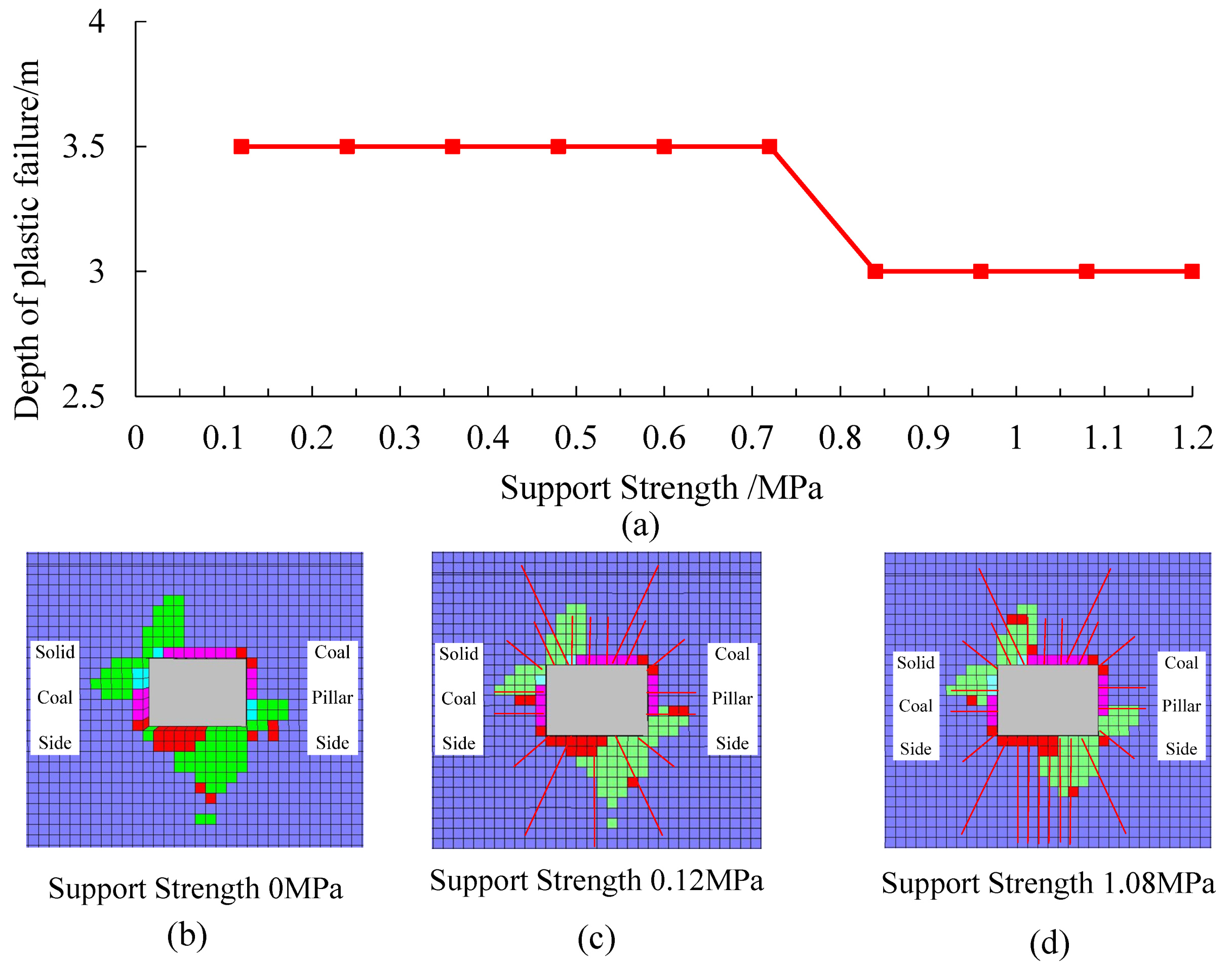
The difference in the thickness of the floor’s hardened layer largely reflected the different support strengths. To visually reflect the effect of the support strength on the failure control of the floor, the number of anchor cables used per roadway floor was represented by different support strengths. As shown in Figure 20, the support strength increased from 0.12 MPa to 1.20 MPa (10 ×Φ21.6 mm anchor cables/m), and the deformation of the surrounding rock was only reduced by 15%. The degree of reduction in the deformation of the surrounding rock is negligible in practical engineering. Based on the above considerations, it can be seen that under the existing engineering conditions, it was difficult to effectively control the plastic failure of the roadway floor by increasing the support strength.
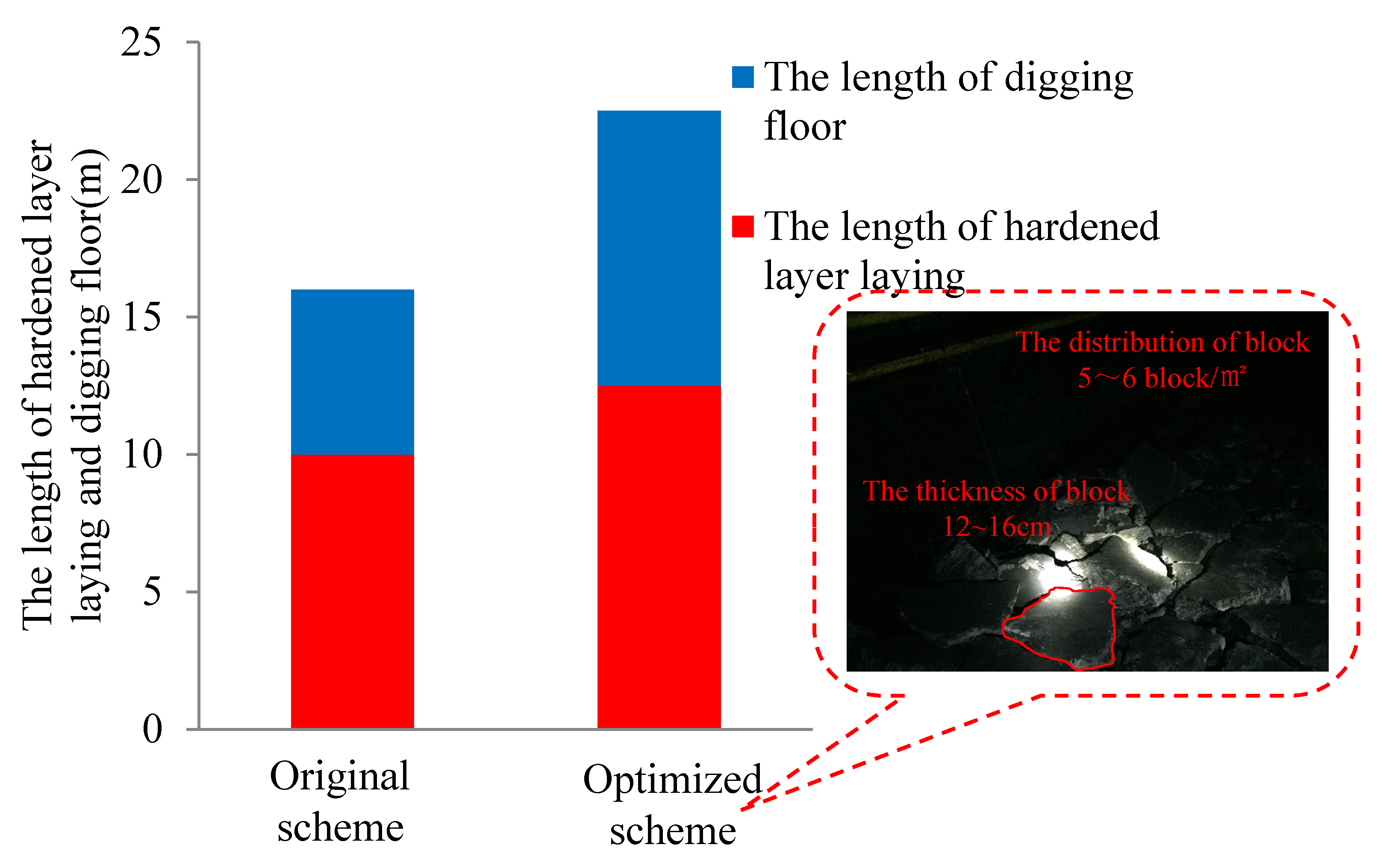
In summary, it is not feasible to use high-strength floor hardening support measures to control the floor heave; thus, all possible measures should consider the characteristics of the non-uniform floor heave. To control the floor heave, a suitable hardened layer thickness should be used to ensure the normal use and easy cleaning of the roadway within a certain period of time. Hence, it is recommended that the thickness of the hardened layer is 120–160 mm.
The length of the hardened layer and floor digging within 8 h are shown in Figure 21. Statistical results mainly reflect the efficiency of the work after changing the scheme. The workload of the digging floor and hardened layer laying was greatly improved in 8 h. The optimized floor heave treatment scheme reduced the concrete usage by 50% compared with the non-optimized scheme, and the laying time was reduced by 20%. For the floor, the broken rock mass and hard soil layer were reduced by approximately 40%. Thus, the efficiency of the floor treatment was greatly improved. Overall, the optimized scheme was 40% more efficient than the original non-optimized scheme.
4.3. Determine Digging Floor Scheme According to Law of Asymmetric Floor Heave
Floor digging work is inevitable for the floor heave in a mining roadway. Moreover, reasonable opportunity and correct positioning are particularly important for floor digging work. According to the monitoring results for the governing law of the floor heave, the advanced support area of the coal face (30 m ahead of the coal face) is the range of the violent influence exerted by the front abutment pressure. The degree of plastic damage to the floor tended to be the largest. However, presently, it is easier to manually break the floor. The digging of the roadway’s floor heave should be outside of the advanced support and preferably within the area adjacent to the coal face. Thus, a more thorough floor treatment can be carried out, while the difficulty of floor digging is reduced. Combined with the analysis of the asymmetric floor heave mechanism, the maximum position of the floor heave should achieve a certain amount of over-digging to ensure the normal operation of the roadway. The maximum position of the floor heave is determined based on the caving coal thickness in the upper section of the panel, and the asymmetric deformation characteristics of the roadway’s adjacent position. Moreover, the installation location of permanent equipment and the location of frequent use, for example, should be placed on the smaller side of the tunnel floor heave, i.e., on the solid coal side of the mining roadway.
5. Conclusions
This paper studied the deformation law of floor heave in the coal pillar roadway under the condition of a soft rock floor in the Dananhu No.1 Coal Mine in China. Theoretical analysis, numerical simulation, and field tests were conducted. The stress environment, deformation, and failure characteristics of the mining roadway in the fully mechanized caving face were analysed. Through the theoretical analysis and numerical simulation of three different top coal thicknesses, the deformation mechanism of surrounding rock failure was studied.
The surrounding rock stress environment of a mining roadway with coal pillar protection in a fully mechanized caving face is non-uniform under the influence of mining. Under the condition of a certain coal thickness, the fracture angle of the main roof strata increases with the increase of the caving coal thickness. The concentration of abutment pressure increases in the position of the mining roadway. Moreover, the degree of deflection of the maximum principal stress around the surrounding rock also increases. When the coal seam thickness exceeds a certain degree, the main roof strata in the minority area are unstable along the edge of the coal pillar and up until the cut, and the surrounding rock stress environment around the roadway returns to the initial geostress state.
Under non-uniform stress field conditions, the floor plastic zone of the coal pillar roadway is asymmetrically distributed, and this causes asymmetric floor heave. As the absolute value of the principal stress and the ratio of the principal stress around the rock surrounding the roadway increase, the asymmetric floor heave becomes more severe. Moreover, as the rotation angle of the principal stress direction increases, the maximum plastic failure depth position of the floor gradually moves toward the middle position of the roadway, and this is the intrinsic reason for the different position distribution of the maximum deformation of the mining roadway’s floor heave.
The deformation of the mining roadway’s floor heave cannot be effectively controlled. The control should be based on the deformation of the floor heave to ensure the normal use and easy cleaning of the roadway within a certain period of time. Thus, a hardening layer with an appropriate thickness should be used. Floor digging work should be carried out as close as possible to the adjacent coal face. The maximum position of the floor heave should ensure a certain amount of over-digging. Moreover, the excavation of the mining roadway should be carried out after the roof activity of the upper goaf stabilizes, so as to reduce the damage and deformation of the roadway floor.
Author Contributions
Conceptualization, H.J.; Methodology, L.W.; Software K.P.; Validation, K.F. and B.P.; Formal Analysis, L.W.; Investigation, K.F.; Resources, B.P.; Data Curation, B.P.; Writing-Original Draft, L.W. and K.P.; Writing-Review & Editing, H.J.; Visualization L.W.; Supervision, H.J.
Funding
This research was funded by National Natural Science Foundation of China, grant number 51604094 and 51674098 and The APC was funded by National Natural Science Foundation of China.
Acknowledgments
We thank Liwen Bianji, Edanz Editing China (www.liwenbianji.cn/ac), for editing the English text of a draft of this manuscript.
Conflicts of Interest
The authors declare no conflict of interest.
References
- Hou, C. Ground Control of Roadways; China University of Mining and Technology Press: Xuzhou, China, 2013. [Google Scholar]
- Zhao, Z.; Ma, N.; Jia, H. Partitioning characteristics of gas channel of coal-rock mass in mining space and gas orientation method. Int. J. Min. Sci. Technol. 2013, 23, 873–877. [Google Scholar] [CrossRef]
- Zhong, Z.; Tu, Y.; Liu, X. Occurrence mechanism and control technology of the floor heave disaster for soft-rock tunnel. Disaster Adv. 2012, 5, 987–992. [Google Scholar]
- Wang, M.; Zhegn, D.; Wang, K. Strain energy analysis of floor heave in longwall gateroads. R. Soc. Open Sci. 2018, 5, 180691. [Google Scholar] [CrossRef] [PubMed] [Green Version]
- Fu, M.; Liu, S.; Su, F. An experimental study of the vibration of a drill rod during roof bolt installation. Int. J. Rock Mech. Min. Sci. 2018, 104, 20–26. [Google Scholar] [CrossRef]
- Gong, P.; Ma, Z.; Ni, X.; Zhang, R. Floor heave mechanism of gob-side entry retaining with fully-mechanized backfilling mining. Energies 2017, 10, 2085. [Google Scholar] [CrossRef]
- Zheng, W.; Zhao, Y.; Bu, Q. The coupled control of floor heave based on a composite structure consisting of bolts and concrete antiarches. Math. Probl. Eng. 2018, 2018, 14. [Google Scholar] [CrossRef]
- Hou, C.; Ma, N. Stress in in-seam roadway sides and limlt equillbrlum zone. J. China Coal Soc. 1989, 4, 21–29. [Google Scholar]
- Hou, C. Key technologies for surrounding rock control in deep roadway. J. China Univ. Min. Technol. 2017, 46, 970–978. [Google Scholar]
- Hou, C. Effective approach for surrounding rock control in deep roadway. J. China Univ. Min. Technol. 2017, 46, 467–473. [Google Scholar]
- He, M.C.; Zhang, G.F.; Wang, G.L.; Xu, Y.L.; Wu, C.Z.; Tang, Q.D. Research on mechanism and application to floor heave control of deep gateway. Chin. J. Rock Mech. Eng. 2009, 28, 2593–2598. [Google Scholar]
- Sun, X.M.; Chen, F.; He, M.C.; Gong, W.L.; Xu, H.C.; Lu, H. Physical modeling of floor heave for the deep-buried roadway excavated in ten degree inclined strata using infrared thermal imaging technology. Tunn. Undergr. Space Technol. 2017, 63, 228–243. [Google Scholar] [CrossRef]
- Guofeng, L.I.; Manchao, H.E.; Zhang, G.; Zhigang, T. Deformation mechanism and excavation process of large span intersection within deep soft rock roadway. Min. Sci. Technol. 2010, 20, 28–34. [Google Scholar]
- Kang, H.; Lu, S. An analysis on the mechanism of roadway floor heave. Chin. J. Rock Mech. Eng. 1991, 10, 362–373. [Google Scholar]
- Guo, G.; Kang, H.; Qian, D.; Gao, F.; Wang, Y. Mechanism for controlling floor heave of mining roadways using reinforcing roof and sidewalls in underground coal mine. Sustainability 2018, 10, 1413. [Google Scholar] [CrossRef]
- Kang, H. Studies of stress state and rock properties on floor heave. Ground Press. Strat. Control 1994, 11, 43–46. [Google Scholar]
- Kang, H.; Li, J.; Yang, J.; Gao, F. Investigation on the Influence of Abutment Pressure on the Stability of Rock Bolt Reinforced Roof Strata Through Physical and Numerical Modeling. Rock Mech. Rock Eng. 2017, 50, 387–401. [Google Scholar] [CrossRef]
- Kang, H.; Lou, J.; Gao, F.; Yang, J.; Li, J. A physical and numerical investigation of sudden massive roof collapse during longwall coal retreat mining. Int. J. Coal Geol. 2018, 188, 25–36. [Google Scholar] [CrossRef]
- Bai, J.B.; Li, W.F.; Wang, X.Y.; Xu, Y.; Huo, L.J. Mechanism of Floor Heave and Control Technology of Roadway Induced by Mining. J. Min. Saf. Eng. 2011, 28, 1–5. [Google Scholar]
- Zhang, Z.; Bai, J.; Chen, Y.; Yan, S. An innovative approach for gob-side entry retaining in highly gassy fully-mechanized longwall top-coal caving. Int. J. Rock Mech. Min. Sci. 2015, 80, 1–11. [Google Scholar] [CrossRef]
- Yang, B.S.; Geng, X.L.; Sun, L.H.; Song, X.Z.; Zhang, L. Research on floor heave mechanism of thick seam roadway in Wuyang coal mine and its control. J. Min. Saf. Eng. 2012, 29, 8–13. [Google Scholar]
- Yang, B.S.; Jia, Y.F.; Sun, L.H.; Li, X.; Gao, B. Experimental research on the continuous “double shell” har-nessing floor heave in high horizontal stress roadway. J. China Coal Soc. 2014, 39, 1504–1510. [Google Scholar]
- Sun, L.; Yang, B.; Yang, W. Reinforcement mechanism and experimental study on con-tinuous double shell of deep roadway. J. Min. Saf. Eng. 2013, 30, 687–691. [Google Scholar]
- Ma, N.J.; Guo, X.F.; Zhao, Z.Q.; Zhao, X.D.; Liu, H.T. Occurrence mechanisms and judging criterion on circular tunnel butterfly rock burst in homogeneous medium. J. China Coal Soc. 2016, 41, 2679–2688. [Google Scholar]
- Jiang, L.; Wu, Q.; Wu, Q.; Wang, P.; Xue, Y.; Kong, P.; Gong, B. Fracture failure analysis of hard and thick key layer and its dynamic response characteristics. Eng. Fail. Anal. 2019, 98, 118–130. [Google Scholar] [CrossRef]
- Jiang, L.; Sainoki, A.; Mitri, H.S.; Ma, N.; Liu, H.; Hao, Z. Influence of fracture-induced weakening on coal mine gateroad stability. Int. J. Rock Mech. Min. Sci. 2016, 88, 307–317. [Google Scholar] [CrossRef]
- Yuan, Y.; Wang, W.; Li, S.; Zhu, Y. Failure Mechanism for Surrounding Rock of Deep Circular Roadway in Coal Mine Based on Min-ing-Induced Plastic Zone. Adv. Civ. Eng. 2018, 2018, 14. [Google Scholar]
- Wang, W.; Yuan, C.; Guo, G.; Yu, W.J. Control of malignant expansion of plastic zone in surrounding rock of rock roadway under the conditions of violent mining. J. Min. Saf. Eng. 2016, 33, 957–964. [Google Scholar]
- Yu, W.; Wang, W.; Chen, X. Field investigations of high stress soft surrounding rocks and deformation control. J. Rock Mech. Geotech. Eng. 2015, 7, 421–433. [Google Scholar] [CrossRef] [Green Version]
- Zhao, Z.Q.; Ma, N.J.; Guo, X.F. Falling principle and support design of butterfly-failure roof in large deformation mining roadways. J. China Coal Soc. 2016, 41, 2932–2939. [Google Scholar]
- Jia, H.; Ma, N.; Zhu, Q. Mechanism and control method of roof fall resulted from butterfly plastic zone penetration. J. China Coal Soc. 2016, 41, 1384–1392. [Google Scholar]
- Qian, M.; Shi, P.; Xu, J. Ground Pressure and Strata Control; China University of Mining and Technology Press: Xuzhou, China, 2010. [Google Scholar]
- Cheng, L.; Zhang, Y. A New Closed-Form Solution of the Side Abutment Pressure Distribution of Roadway. Adv. Civ. Eng. 2018, 2018, 10. [Google Scholar] [CrossRef]
Figure 1.
The location map of the Dananhu No.1 Coal Mine.

Figure 2.
Roof, coal seam and floor strata structure peephole results for coal seam of panel 1306 return airway roadway.
Figure 2.
Roof, coal seam and floor strata structure peephole results for coal seam of panel 1306 return airway roadway.
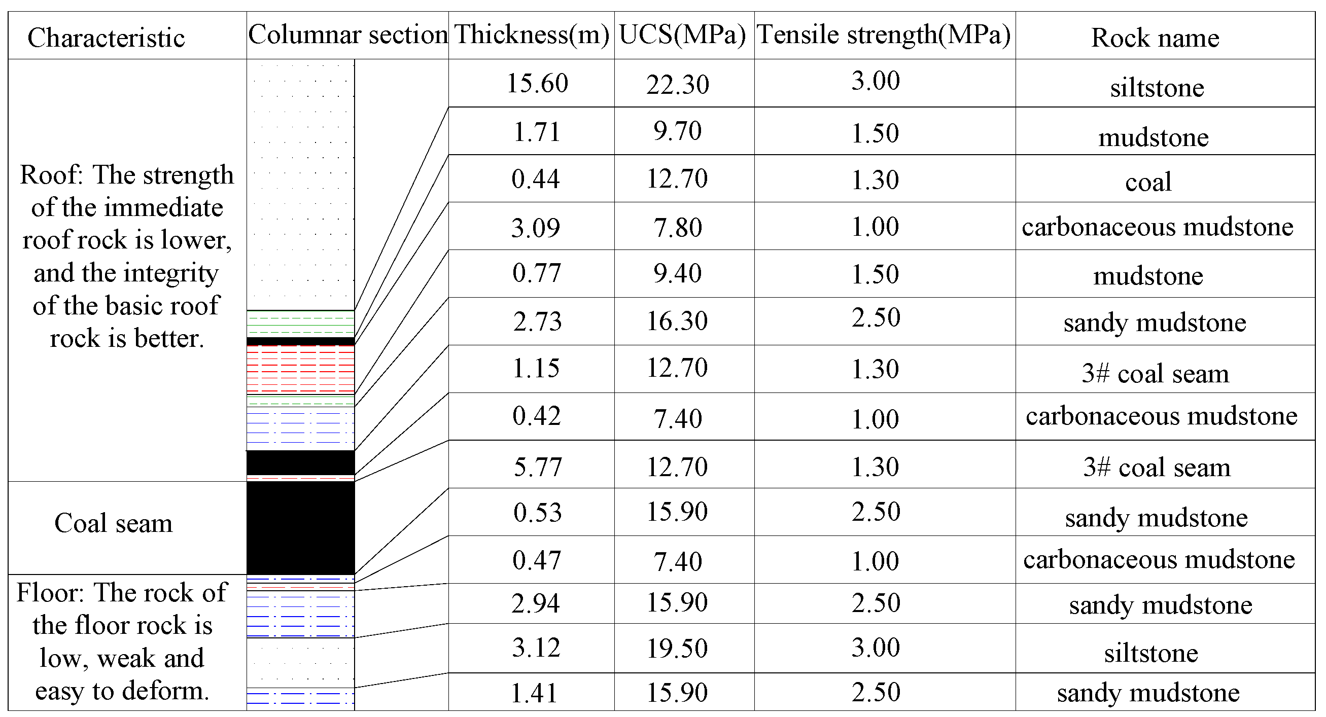
Figure 3.
Mining roadway layout of panels 1304 and 1306.
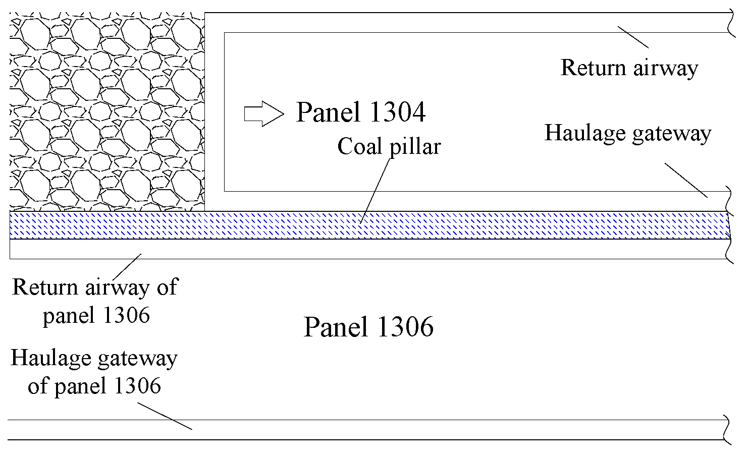
Figure 4.
Statistical results of floor heave law and thickness of caving coal.
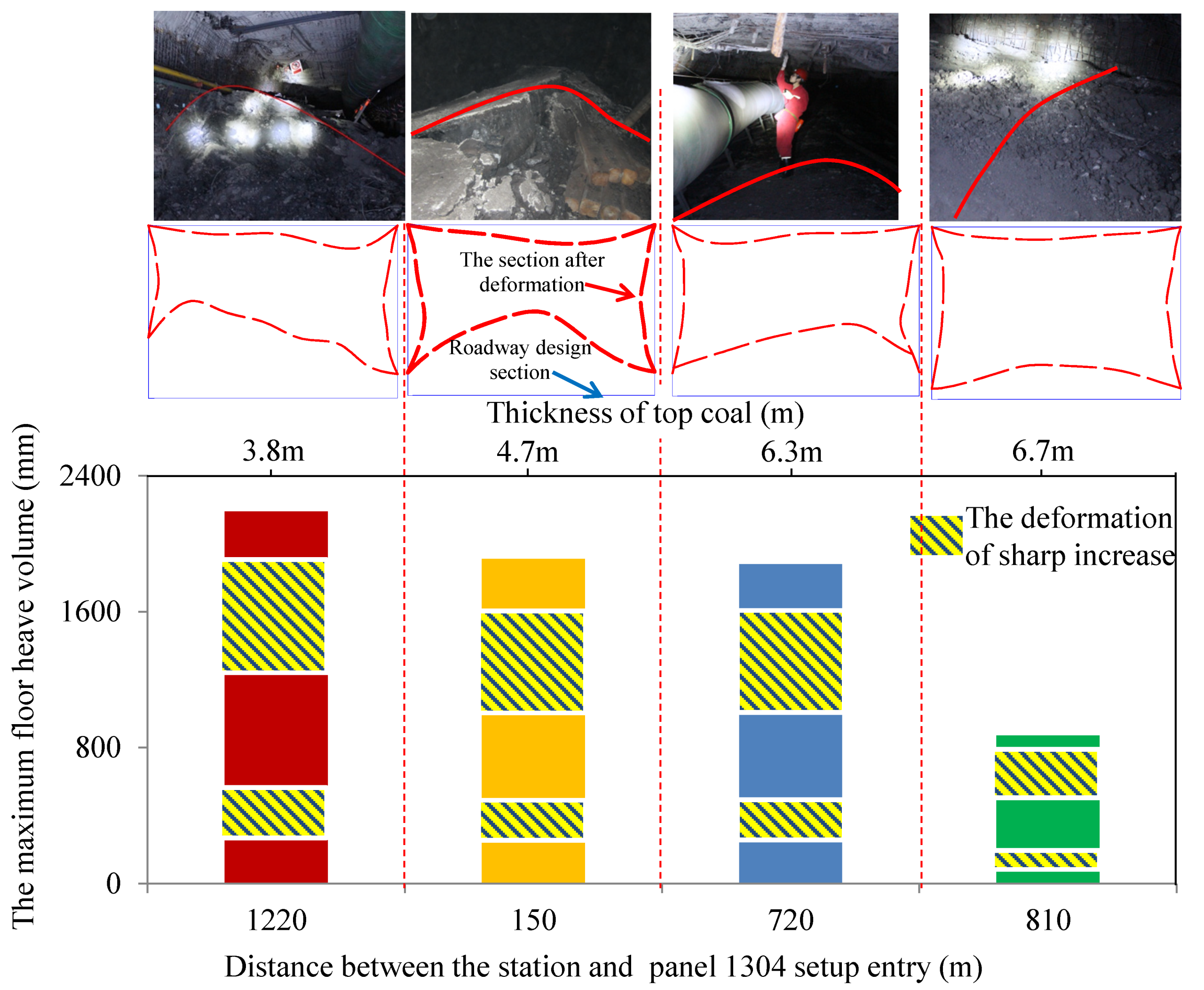
Figure 5.
Side surface-connected fissure of panel 1304. (a) Fissure size 0.32m, Small size of fissure; (b) Fissure size 0.51m, Large size of fissure; (c) Fissure size 0.53m, Fractured fissure.
Figure 5.
Side surface-connected fissure of panel 1304. (a) Fissure size 0.32m, Small size of fissure; (b) Fissure size 0.51m, Large size of fissure; (c) Fissure size 0.53m, Fractured fissure.
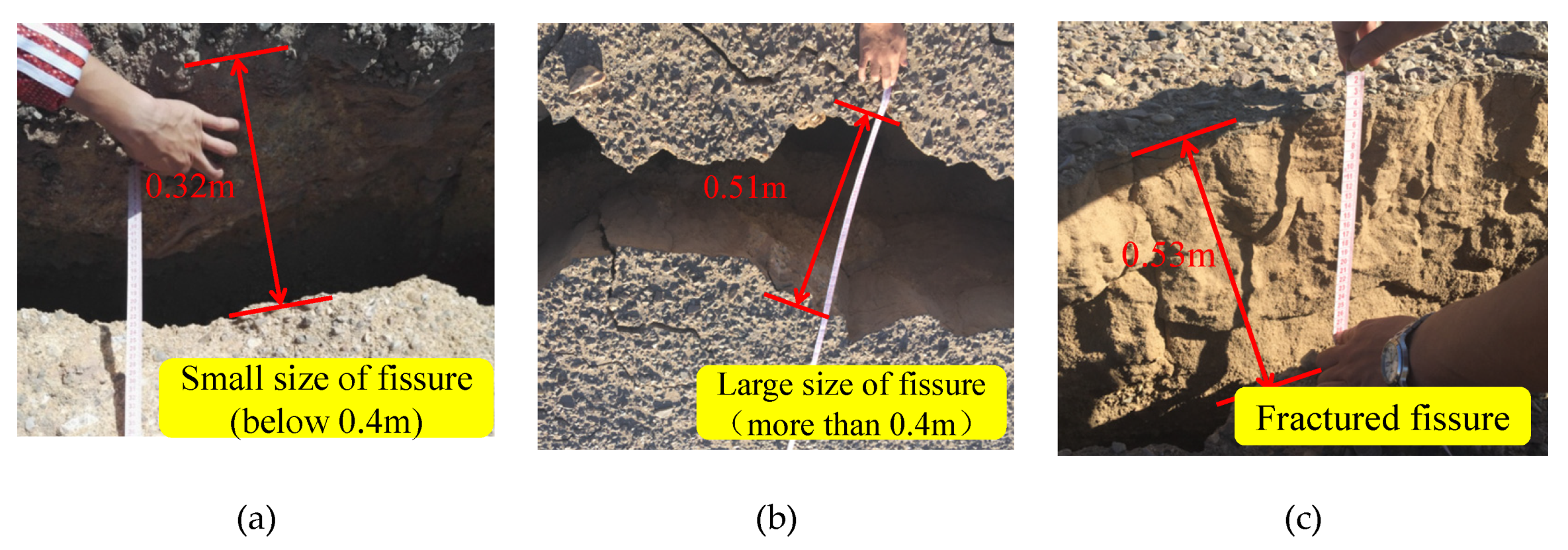
Figure 6.
Stress environment of rock surrounding mining roadway with different caving coal thicknesses and roadway deformation profiles. (a) Small thickness of top coal (2 m); (b) Middle thickness of top coal (4 m); (c) Large thickness of top coal (6 m).
Figure 6.
Stress environment of rock surrounding mining roadway with different caving coal thicknesses and roadway deformation profiles. (a) Small thickness of top coal (2 m); (b) Middle thickness of top coal (4 m); (c) Large thickness of top coal (6 m).
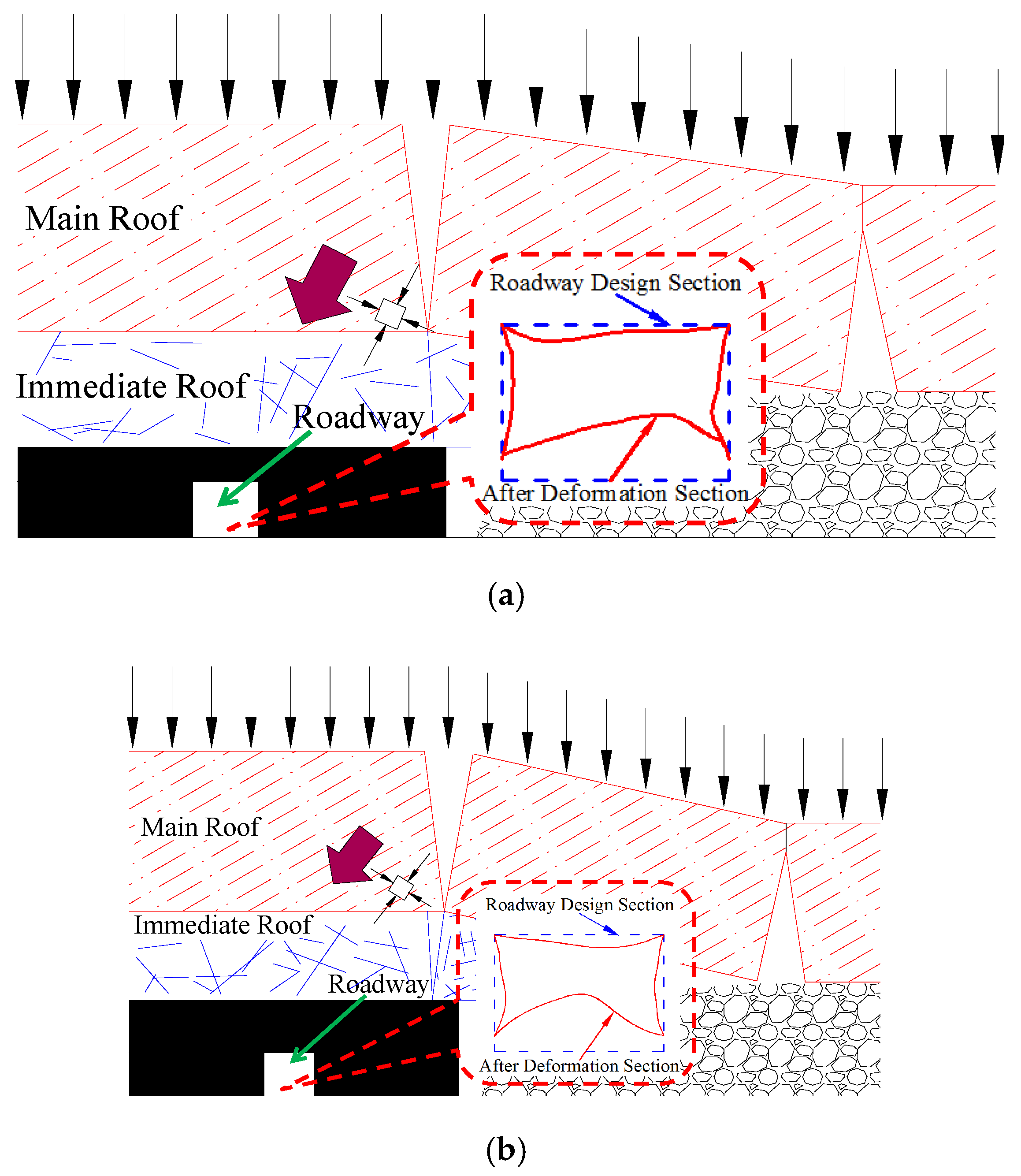

Figure 7.
Mechanical analysis of rotating rock block.

Figure 8.
Stress environment of surrounding rock around roadway with main roof fractured and roadway deformation profile.
Figure 8.
Stress environment of surrounding rock around roadway with main roof fractured and roadway deformation profile.

Figure 9.
Numerical model with different top coal thicknesses. (a) Top 2 m of coal; (b) Top 4 m of coal; (c) Top 6 m of coal.
Figure 9.
Numerical model with different top coal thicknesses. (a) Top 2 m of coal; (b) Top 4 m of coal; (c) Top 6 m of coal.
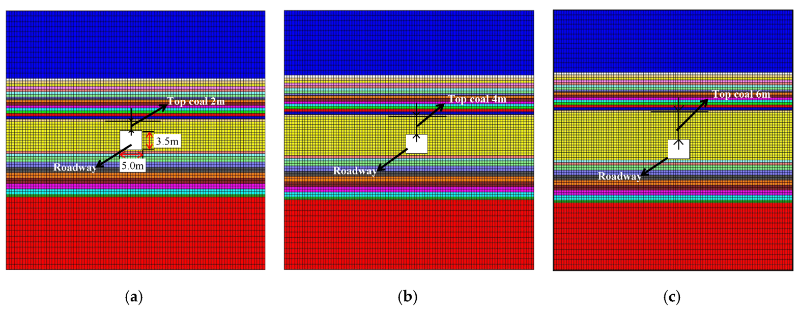
Figure 10.
Simulation results of roadway’s plastic zone distribution under different stress environments at top 2 m of coal (β = 30°). Note: λ is the principal stress ratio; β is the deflection direction of principal stress.
Figure 10.
Simulation results of roadway’s plastic zone distribution under different stress environments at top 2 m of coal (β = 30°). Note: λ is the principal stress ratio; β is the deflection direction of principal stress.
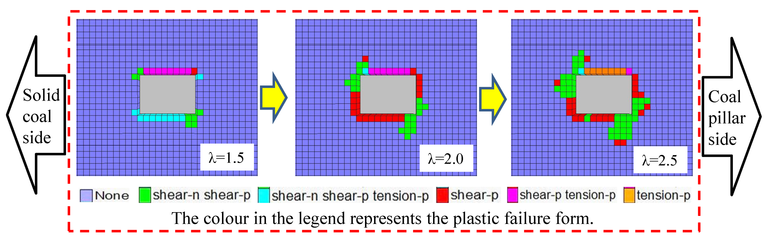
Figure 11.
Simulation results of roadway’s plastic zone distribution under different stress environments at top 4 m of coal (β = 45°). Note: λ is the principal stress ratio; β is the deflection direction of the principal stress.
Figure 11.
Simulation results of roadway’s plastic zone distribution under different stress environments at top 4 m of coal (β = 45°). Note: λ is the principal stress ratio; β is the deflection direction of the principal stress.

Figure 12.
Comparison of field photos of coal pillar roadway, and numerical simulation results of surrounding rock deformation profile.
Figure 12.
Comparison of field photos of coal pillar roadway, and numerical simulation results of surrounding rock deformation profile.

Figure 13.
Simulation results of roadway’s plastic zone distribution under different stress environments for top coal at 6 m (β = 10°). Note: λ is the principal stress ratio; β is the deflection direction of principal stress.
Figure 13.
Simulation results of roadway’s plastic zone distribution under different stress environments for top coal at 6 m (β = 10°). Note: λ is the principal stress ratio; β is the deflection direction of principal stress.
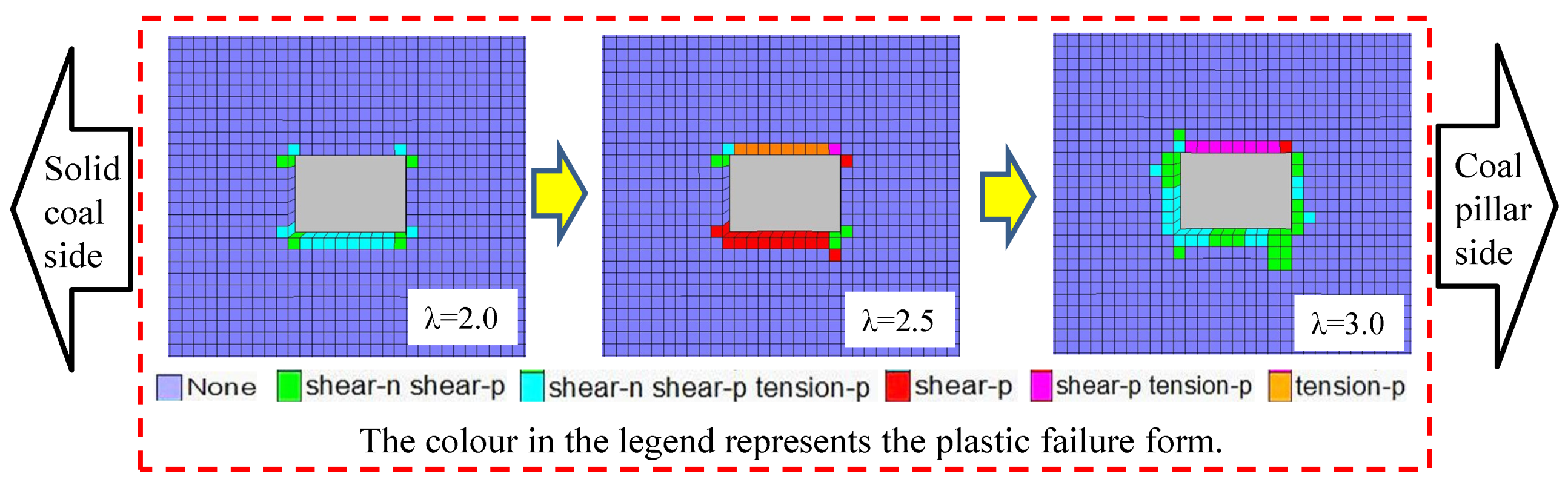
Figure 14.
Calculation model of plastic zone for rock surrounding non-equal pressure circular roadway.
Figure 14.
Calculation model of plastic zone for rock surrounding non-equal pressure circular roadway.

Figure 15.
General shape of plastic zone in circular roadway obtained from theoretical calculation (P3 = 20 MPa, a = 2 m, C = 3 MPa, φ = 25°).
Figure 15.
General shape of plastic zone in circular roadway obtained from theoretical calculation (P3 = 20 MPa, a = 2 m, C = 3 MPa, φ = 25°).

Figure 16.
Drawing system interface of plastic zone for rock surrounding roadway.
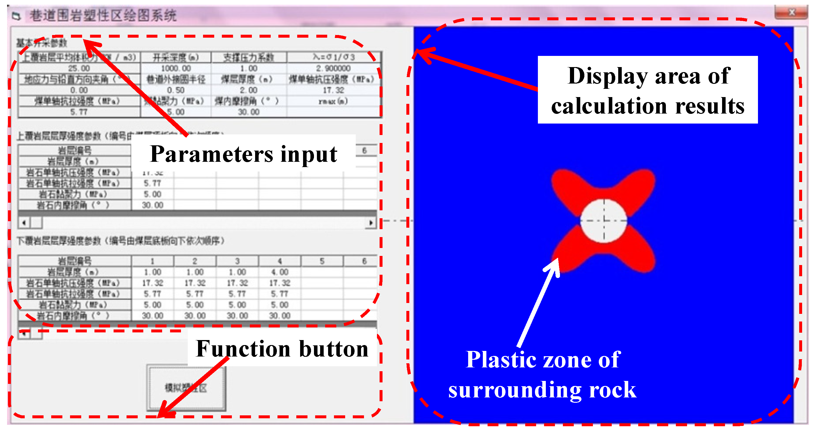
Figure 17.
Relationship between shape of butterfly-shaped plastic zone and direction of principal stress in rock surrounding roadway. Note: α is the angle between the maximum principal stress and the vertical direction; the clockwise direction is positive.
Figure 17.
Relationship between shape of butterfly-shaped plastic zone and direction of principal stress in rock surrounding roadway. Note: α is the angle between the maximum principal stress and the vertical direction; the clockwise direction is positive.
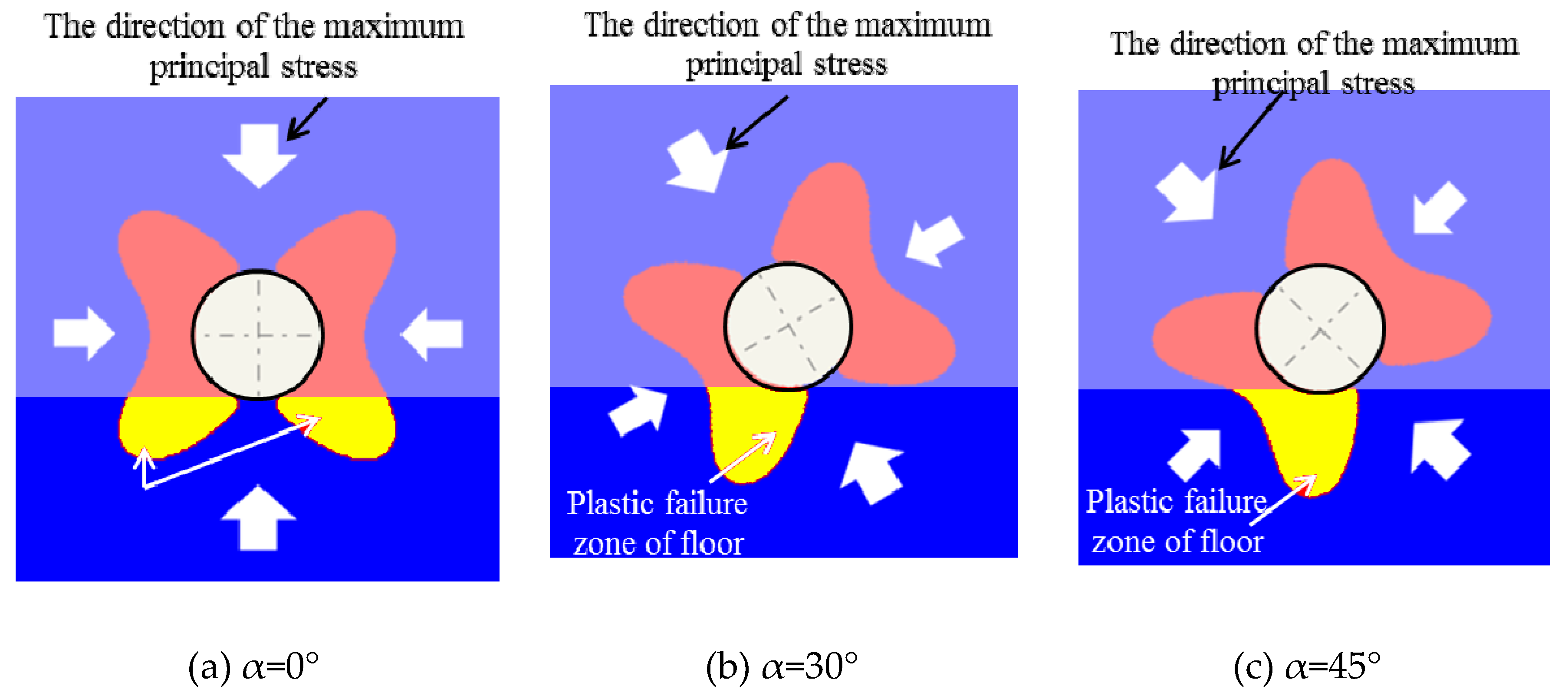
Figure 18.
Layout of test roadway and measuring station.
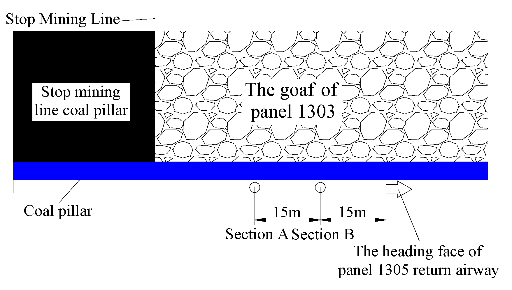
Figure 19.
Monitoring curve of floor heave deformation.
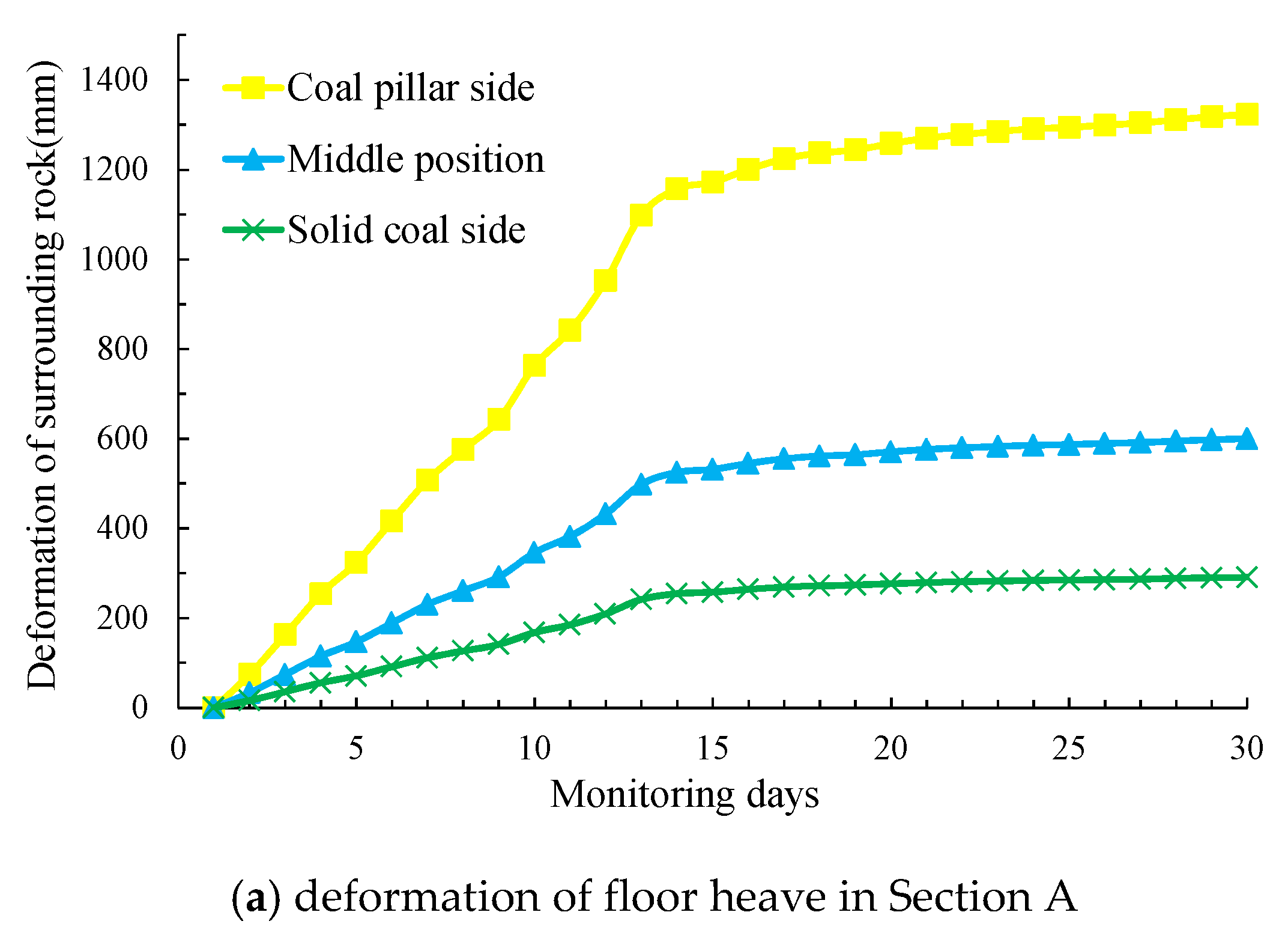
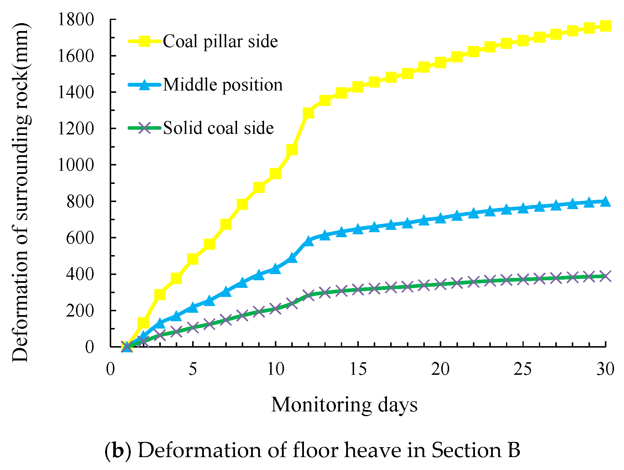
Figure 20.
Curve of plastic zone range along with increase of support intensity.

Figure 21.
Length of hardened layer and floor digging within 8 h.

Table 1.
Numerical simulation scheme.
| Simulation Scheme | Thickness of Roadway Caving Coal | Deflection Direction of Principal Stress (°) | Principal Stress Ratio | Principal Stress (MPa) | ||
|---|---|---|---|---|---|---|
| σ1 | σ2 | σ3 | ||||
| Scheme 1 | 2 m | 30° | 1.5 | 9.75 | 7.50 | 6.50 |
| 2.0 | 13.00 | 9.00 | 6.50 | |||
| 2.5 | 16.25 | 10.00 | 6.50 | |||
| Scheme 2 | 4 m | 45° | 2.0 | 13.00 | 9.00 | 6.50 |
| 2.5 | 16.25 | 10.00 | 6.50 | |||
| 3.0 | 19.50 | 12.00 | 6.50 | |||
| 60° | 2.0 | 13.00 | 9.00 | 6.50 | ||
| 2.5 | 16.25 | 10.00 | 6.50 | |||
| 3.0 | 19.50 | 12.00 | 6.50 | |||
| Scheme 3 | 6 m | 10° | 1.0 | 6.50 | 6.50 | 6.50 |
| 1.5 | 9.75 | 7.50 | 6.50 | |||
| 2.0 | 13.00 | 9.00 | 6.50 | |||
Table 2.
Numerical simulation of rock’s physical and mechanical parameters.
| Lithology | Bulk Density (Kg/m3) | K (GPa) | G (GPa) | C (MPa) | Φ (°) | |
|---|---|---|---|---|---|---|
| Carbonaceous mudstone | 2250 | 6.0 | 3.5 | 2.5 | 25 | 1.0 |
| Mudstone | 2300 | 6.0 | 3.5 | 3.0 | 27 | 1.5 |
| Sandy mudstone | 2420 | 8.0 | 5.0 | 5.0 | 29 | 2.5 |
| 3# coal seam | 1500 | 7.0 | 4.5 | 4.0 | 28 | 1.5 |
| Siltstone | 2700 | 14.3 | 9.0 | 6.0 | 30 | 3.0 |
© 2019 by the authors. Licensee MDPI, Basel, Switzerland. This article is an open access article distributed under the terms and conditions of the Creative Commons Attribution (CC BY) license (http://creativecommons.org/licenses/by/4.0/).
Share and Cite
MDPI and ACS Style
Jia, H.; Wang, L.; Fan, K.; Peng, B.; Pan, K. Control Technology of Soft Rock Floor in Mining Roadway with Coal Pillar Protection: A case study. Energies 2019, 12, 3009. https://doi.org/10.3390/en12153009
AMA Style
Jia H, Wang L, Fan K, Peng B, Pan K. Control Technology of Soft Rock Floor in Mining Roadway with Coal Pillar Protection: A case study. Energies. 2019; 12(15):3009. https://doi.org/10.3390/en12153009
Chicago/Turabian StyleJia, Housheng, Luyao Wang, Kai Fan, Bo Peng, and Kun Pan. 2019. "Control Technology of Soft Rock Floor in Mining Roadway with Coal Pillar Protection: A case study" Energies 12, no. 15: 3009. https://doi.org/10.3390/en12153009
Note that from the first issue of 2016, this journal uses article numbers instead of page numbers. See further details here.