Multi-User AF Relay Networks with Power Allocation and Transfer: A Joint Approach

1
Department of Electronics & Communication Engineering, IGTUW, Delhi 110006, India
2
School of Electrical & Electronic Engineering, University College Dublin (UCD), Dublin 4, Ireland
3
Institute for Digital Communications (IDCOM), University of Edinburgh, Edinburgh EH9 3FG, UK
*
Author to whom correspondence should be addressed.
Energies 2019, 12(16), 3157; https://doi.org/10.3390/en12163157
Submission received: 7 July 2019
/
Revised: 4 August 2019
/
Accepted: 13 August 2019
/
Published: 16 August 2019
(This article belongs to the Special Issue Green Radio, Energy Harvesting, and Wireless-Powered Communications for Beyond-5G Wireless Systems)
Abstract
:The Internet-of-Things (IoT) framework has been considered as an enabler of the smart world where all devices will be deployed with extra-sensory power in order to sense the world as well as communicate with other sensor nodes. As a result, smart devices require more energy. Therefore, energy harvesting (EH) and wireless power transfer (WPT) emerge as a remedy for relieving the battery limitations of wireless devices. In this work, we consider a multi-user amplify-and-forward (AF)-assisted network, wherein multiple source nodes communicate with destination nodes with the help of a relay node. All the source nodes and the relay node have the capability of EH. In addition, to cope with a single point of failure i.e., failure of the relay node due to the lack of transmit power, we consider the WPT from the source nodes to the relay node. For WPT, a dedicated energy control channel is utilized by the source nodes. To maximize the sum rate using a deadline, we adopt a joint approach of power allocation and WPT and formulate an optimization problem under the constraints of the battery as well as energy causality. The formulated problem is non-convex and intractable. In order to make the problem solvable, we utilize a successive convex approximation method. Furthermore, an iterative algorithm based on the dual decomposition technique is investigated to get the optimal power allocation and transfer. Numerical examples are used to illustrate the performance of the proposed iterative algorithm.
1. Introduction
In today’s smart world, wireless communication services are growing in demand exponentially. The Internet-of-Things (IoT) framework has been viewed as an enabler of the smart world. The key requirements to enable IoT services are prolonging the lifetime of operating nodes and extending the coverage range [1,2]. Since relaying schemes are paramount for improving coverage, capacity, and reliability of wireless networks, the lifetime of wireless networks can be enhanced by deploying intermediate energy harvesting (EH) relay nodes, thus, we don’t need to replace the battery sporadically [3,4,5].
As a result of the aforementioned advantages, EH cooperative communication can easily become the backbone of modern, green, smart wireless networks. However, the design challenges of EH wireless networks lie in the fact that solar, wind, and thermoelectric energy, which are common environmental energy sources, are intermittent and random in nature. These common energy sources are not always available. Hence, for transmission reliability, these uncertainties become more challenging for designing EH communication systems. In such a scenario, a promising solution has emerged as regards the wireless power transfer (WPT) in an EH relay-assisted network, wherein EH nodes transfer the energy using dedicated radio frequency (RF) signals. RF-enabled WPT has several practical advantages, such as a small receiver form factor, a low production cost, a wide operating range, and efficient energy multi-casting.
The joint transfer of information and energy leads to a new paradigm referred to as simultaneous wireless information and power transfer (SWIPT) [6]. With the recent advancements in antenna technologies and RF EH circuits, SWIPT will become a key building block of numerous popular industrial and commercial systems in the future, including upcoming IoT technology consisting of billions of communicating and sensing devices and large-scale wireless sensor networks (WSNs) [7,8].
Cooperative communication mitigates wireless channel fading and improves the link reliability by utilizing the spatial diversity gains. There have been a lot of recent studies on energy management in EH cooperative networks [9,10,11,12,13,14]. The power control scheme was investigated in [9] with the non-causal knowledge of energy state information (ESI) [14]. The authors in [10] extended the work of [9] regarding finite batteries.Fading channels were considered in [11,12] as well as EH problems. The optimal energy allocation strategy was obtained in [11,12]. However, the authors in [13,14,15] explored the idea of energy cooperation for EH relay networks, wherein [15] a dual-dimensional directional water-filling strategy was investigated to maximize the throughput. The ambient EH has been studied in [16,17,18]. The authors in [16] studied power allocation in decode-and-forward (DF) relaying with deterministic EH models. With a finite horizon of transmission blocks, the throughput maximization problem was studied for the cases of delay-constrained traffic or no-delay-constrained traffic. A joint problem of power allocation and time scheduling was investigated in [17] for a dual-hop relay system with an EH source. In [18], power allocation schemes were designed to maximize the throughput of a dual-hop amplify-and-forward (AF) relay system; while the authors in [19,20] considered multiple source-destination pairs and proposed relay transmission strategies. Dedicated EH from RF signals is naturally appropriate to cooperative networks as it facilitates information relaying. In this direction, the major design concern is to find a suitable time sharing or power splitting ratio to achieve the best trade-off between EH and signal relaying. More recently, SWIPT methods have been investigated in [21,22,23,24]. However, none of these aforementioned works has studied joint power allocation and WPT in multi-user AF-assisted relay networks.
In this work, we consider a multi-user AF assisted network and focus on maximizing the sum rate of the designed framework by jointly optimizing optimal power allocation and transfer. We assume that each transmitter (sources/relay) has the capability of EH and that SWIPT takes place from the source nodes to the relay node only.
In order to improve the reliability of the relay node, the source nodes use a dedicated energy control channel to transfer the harvested energy to the relay. Notice that the dedicated energy control channel is assumed to be orthogonal to the data transfer channel. Since the relay node operates in AF mode, the relay-assisted network suffers from a noise magnification problem. This presents an interesting question: how can we balance energy disbursement and energy transfer between EH nodes. In respect to this, we formulate an optimization problem for maximizing the sum rate by considering both energy and battery causality constraints. The formulated problem is non-convex and intractable in nature. In order to make the problem solvable, we utilize a successive convex approximation method. Furthermore, an iterative algorithm based on the dual decomposition technique is proposed to achieve the optimal strategy.
The rest of this work is divided into the following sections. The system model, EH and WPT model, and the formulation of an optimization problem are described in Section 2. The proposed strategy is illustrated in Section 3. The numerical results are given in Section 4. We conclude the paper in Section 5.
2. Preliminaries
2.1. System Model
Consider an EH dual-hop AF-assisted relay network consisting of N EH source nodes , one relay node and N destination nodes , as depicted in Figure 1. A single antenna is deployed at each node in the network. As a result of long distance and deep fading, there is no direct link between and , . The nodes , , and R can harvest energy from ambient energy sources and store them in batteries. We adopt a time-slotted model with a unit time duration for each time slot. The total time slot length is . Furthermore, the battery capacity i.e., energy queues, at each , , and R are and units of energy, respectively. At the end of each slot, the status of batteries is updated. We further assume frequency flat fading channels between all links. In each time slot, the relay R works in half-duplex (HD) fashion. Suppose , indicates the time slot index. In the first phase, the signal received by the relay node in the time slot is written as
where represents the transmission power of the node , is the transmitted message with , is the channel coefficient from node to R, is AWGN at node R. The signal transmitted by node R after amplification is given by , where , and is the transmission power of node R. In the second phase, the received signal at the destination node in the time slot is expressed as
where , and are defined similar to , and for the link from R to the .
Using (2), we can compute the sum rate over consecutive time slots as
where , , and signal-to-interference-plus-noise ratio (SINR) at node is obtained as
with and .
2.2. Energy Harvesting and Power Transfer Model
At the time slot, and are the amounts of harvested energy at and R nodes, respectively, and we assume the energy profiles are non-casually known before data transmission [14]. Furthermore, during the slot, each source node , transfers amount of energy to R with an efficiency of , by utilizing a dedicated control channel with channel coefficients . Thus, when node has enough energy, it can share a part of its harvested energy with node R to extend the lifetime of the relay-assisted network. The power allocation and transfer depends on the following two energy causality constraints:
where , and indicates the energy control channel from node to node R at the time slot. Furthermore, the battery storage constraints are required to control the battery overflow at , and R nodes, respectively, and are given by
where and are the fixed processing power consumed at the source for energy transfer and at the relay node in energy conversion, respectively.
2.3. Problem Formulation and Transformation
From (5)–(8), the optimization problem for joint power allocation and transfer can be constructed as
where . Since the objective function in (9) is non-concave, to resolve this, we adopt the following change of variables: and . After the change of variables, we can rewrite the problem (P.1) as follows:
where , , and where and are defined as
After applying the above change of variables, and in ((P.2)) are convex, while and become non-convex. Let and , the problem (P.2) is equivalently written as
where with , and can be regarded as accumulated power dissipation profiles. The objective function in (P.3) is still non-concave, and thus, an SCA method is utilized here in order to transform the non-tractable objective function of into a tractable one as follows:
where is given as
The lower bound in (25) always holds true if we choose and as in [25]:
for . Note that when we choose and according to (26) and (27), at , (25) becomes tight with equality.
3. Proposed Power Allocation and Transfer Algorithm
By fixing the values of and and for given and , is convex, and thus, it can be solved with convex optimization tools [26]. Using a dual decomposition technique, we propose an iterative algorithm. The dual problem can be defined as follows [26]:
where is the Lagrangian function of which is written as
The dual problem (28) can be resolved iteratively as described in following subsections.
3.1. Subproblem Solution
The values of power allocation and transfer at the time slot for the node and node R can be computed iteratively using the Karush–Kuhn–Tucker (K.K.T.) conditions. The , , and are obtained by taking the partial derivative with respect to , , and and by equating the result to zero. The detailed derivation which is straight forward is omitted here.
3.2. Master Problem
With the updated multipliers, we compute , and . Next, and using (26) and (27) are recomputed in order to further enhance the lower bound performance in (24). We repeat this procedure until convergence of the algorithm. The proposed algorithm is outlined in Algorithm 1 for the fixed values of and .
| Algorithm 1: Proposed algorithm for given values of and . |
| 1: Set as the maximum number of iterations with step sizes 2: Initialize , and ; 3: Initialize , , , , , , , and . 4: repeat 5: repeat(Solving (P4)) 6: Compute and and ; 7: Compute , , , , , and using (30)–(35). 8: until convergence; 9: Compute and using (26) and (27) 10: Set , , and and . 11: until convergence or . |
Theorem 1.
The optimal of the problem must fulfill the following two conditions:
Proof.
This theorem can be proved by contradiction. Let be the optimal solution of . First suppose is true for . Then, we can ameliorate to achieve an increased sum rate of , directly implied by utilizing the SINR obtained in , without conflicting with any other constraints in . Thus, (T.1) contradicts with the optimality of .
Next, suppose is fulfilled with strict inequality, for . By reducing and increasing and , we can get an ameliorated sum rate, while fulfilling other conditions in . Thus, (T.2) directly contradicts with the optimality of . Hence, it is proved. □
Now, we update the values of and with the help of the following lemma.
Lemma 1.
To obtain the maximum sum rate, the auxiliary variables and should be updated as and , for .
Proof.
To maximize the sum rate, the auxiliary variables and in the outer loop can be illustrated as
where denotes the sum rate achieved by the Algorithm 1. It is very hard to exhaustively search over all values of and due to the very high computational complexity. Therefore, we propose a two-step technique to find the values of and . As the first step, relax the battery storage constraints in (P.4) by assuming and , for , and , and find the optimal using the Algorithm 1. In the next step, we recompute the optimal solution by updating and , for . This enables us to rectify the solutions by following the track of and . □
4. Numerical Results
The path loss models given by dB (d: distance in km) [27,28] are adopted for the data transfer and the dedicated power transfer channels from , to R, while the 3GPP path loss model, given by dB, is used for the channels from R to , . The distance from , to R is considered to be 1 m [28,29]. The thermal noise density and the channel bandwidth are considered as dBm/Hz and 1 MHz. The value of interference suppression factor is set to . mJ and mJ are uniformly distributed EH profiles considered for the simulation. For simplicity, we assume that the EH profiles of all the source nodes are , whilst the EH profiles for node R is . The battery capacity at each , , and R nodes is assumed to be mJ. We consider two scenarios: (1) ; (2) , for . Furthermore, we set . The distances from , to R and from R to , are indicated by and , respectively. In addition, we set and . For better performance comparison, we also simulated the without WPT transmission.
Figure 2 validates the convergence behavior of the algorithm for and . Note that Figure 2 is plotted for a single channel realization. From this figure, we find that the sum rate increases monotonically when the number of iterations increases. In addition, it is noticed that the algorithm converges within four iterations which reflects the effectiveness of the algorithm.
Figure 3 and Figure 4 illustrate the throughput performance of the network in terms of sum rate for each time index in scenario 1 and scenario 2. In this example, we also include the average sum rate of the network without WPT. In both scenarios, it can be observed that the sum rate performance of the algorithm with energy transfer is much better than that without energy transfer. It can also be observed in Figure 4 that for better EH conditions at the , nodes compared to the condition at the R node, the sum rate performance is remarkably enhanced at the end of the time.
Figure 5 shows the achievable sum rate performance of the system when for m and m. Since the EH rate at the source nodes is the worst, the effect of power transfer from the source nodes to the relay node is almost zero and therefore the performance of the system with WPT is identical to that without WPT.
Figure 6 illustrates the impact of the relay’s position on the average sum rate performance. The parameter settings are as follows: We set and m. The distance from to R and from R to are represented b and , respectively, and a distance ratio is defined as . From Figure 6, we can observe that when m, the average sum rate performance is dominated by the energy transfer rate, , and the highest sum rate performance can be achieved when the relay node is placed closer to the source node.
5. Conclusions
We studied a joint design of power allocation and transfer for multi-user AF-assisted networks with EH. We focused on maximizing the achievable sum rate using a deadline, subject to the battery and energy causality constraints at the , , and R nodes, and proposed an iterative algorithm for obtaining the near-optimal solution using successive convex approximation and dual decomposition techniques. Through numerical simulation, we found that the multi-user AF-assisted network with energy transfer achieves a significant sum rate enhancement over the one without WPT.
Author Contributions
R.Y. simulated the proposed method and analyzed the results and wrote the paper; K.S. and S.B. proposed the problem and helped in designing the system model and the problem formulation; A.K. supervised this work.
Funding
This research received no external funding.
Conflicts of Interest
The authors declare no conflict of interest.
References
- Zanella, A.; Bui, N.; Castellani, A.; Vangelista, L.; Zorzi, M. Internet of Things for smart cities. IEEE Internet Things J. 2014, 1, 22–32. [Google Scholar] [CrossRef]
- Zhu, C.; Leung, V.C.M.; Shu, L.; Ngai, E.C.H. Green Internet of Things for smart world. IEEE Access 2015, 3, 2151–2162. [Google Scholar] [CrossRef]
- Medepally, B.; Mehta, N.B. Voluntary energy harvesting relays and selection in cooperative wireless networks. IEEE Trans. Wirel. Commun. 2010, 9, 3543–3553. [Google Scholar] [CrossRef]
- Kang, J. Toward secure energy harvesting cooperative networks. IEEE Commun. Mag. 2015, 53, 114–121. [Google Scholar] [CrossRef]
- Gunduz, D.; Michelusi, S.K.N.; Zorzi, M. Designing intelligent energy harvesting communication systems. IEEE Commun. Mag. 2014, 52, 210–216. [Google Scholar] [CrossRef]
- Gupta, A.; Singh, K.; Sellathurai, M. Time-switching EH-based joint relay selection and resource allocation algorithms for multi-user multi-carrier AF relay networks. IEEE Trans. Green Commun. Netw. 2019, 3, 505–522. [Google Scholar] [CrossRef]
- Bi, S.; Ho, C.K.; Zhang, R. Wireless powered communication: Opportunities and challenges. IEEE Commun. Mag. 2015, 53, 117–125. [Google Scholar] [CrossRef]
- Zhou, X.; Zhang, R.; Ho, C.K. Wireless information and power transfer: Architecture design and rate-energy tradeoff. IEEE Trans. Commun. 2013, 61, 4754–4767. [Google Scholar] [CrossRef]
- Yang, J.; Ulukus, S. Optimal packet scheduling in an energy harvesting communication system. IEEE Trans. Commun. 2012, 60, 220–230. [Google Scholar] [CrossRef]
- Tutuncuoglu, K.; Yener, A. Optimum transmission policies for battery limited energy harvesting nodes. IEEE Trans. Wirel. Commun. 2012, 11, 1180–1189. [Google Scholar] [CrossRef]
- Ho, C.K.; Zhang, R. Optimal energy allocation for wireless communications with energy harvesting constraints. IEEE Trans. Signal Process. 2012, 60, 4808–4818. [Google Scholar] [CrossRef]
- Ozel, O.; Tutuncuoglu, K.; Yang, J.; Ulukus, S.; Yener, A. Transmission with energy harvesting nodes in fading wireless channels: Optimal policies. IEEE J. Sel. Areas Commun. 2011, 29, 1732–1743. [Google Scholar] [CrossRef]
- Singh, K.; Ku, M.; Lin, J. Joint power control and energy transfer for energy harvesting relay networks. In Proceedings of the IEEE International Conference on Communications (ICC), Kuala Lumpur, Malaysia, 22–27 May 2016; pp. 1–5. [Google Scholar]
- Singh, K.; Ku, M.; Lin, J.; Ratnarajah, T. Toward optimal power control and transfer for energy harvesting amplify-and-forward relay networks. IEEE Trans. Wirel. Commun. 2018, 17, 4971–4986. [Google Scholar] [CrossRef]
- Gurakan, B.; Ozel, O.; Yang, J.; Ulukus, S. Energy cooperation in energy harvesting communications. IEEE Trans. Commun. 2013, 61, 4884–4898. [Google Scholar] [CrossRef]
- Huang, C.; Zhang, R.; Cui, S. Throughput maximization for the gaussian relay channel with energy harvesting constraints. IEEE J. Sel. Areas Commun. 2013, 31, 1469–1479. [Google Scholar] [CrossRef]
- Luo, Y.; Zhang, J.; Letaief, K.B. Optimal scheduling and power allocation for two-hop energy harvesting communication systems. IEEE Trans. Wirel. Commun. 2013, 12, 4729–4741. [Google Scholar] [CrossRef]
- Minasian, A.; ShahbazPanahi, S.; Adve, R.S. Energy harvesting cooperative communication systems. IEEE Trans. Wirel. Commun. 2014, 13, 6118–6131. [Google Scholar] [CrossRef]
- Ding, Z.; Perlaza, S.M.; Esnaola, I.; Poor, H.V. Power allocation strategies in energy harvesting wireless cooperative networks. IEEE Trans. Wirel. Commun. 2014, 13, 846–860. [Google Scholar] [CrossRef]
- Chen, H.; Li, Y.; Jiang, Y.; Ma, Y.; Vucetic, B. Distributed power splitting for SWIPT in relay interference channels using game theory. IEEE Trans. Wirel. Commun. 2015, 14, 410–420. [Google Scholar] [CrossRef]
- Huang, K.; Lau, V.K.N. Enabling wireless power transfer in cellular networks: Architecture modeling and deployment. IEEE Trans. Wirel. Commun. 2014, 13, 902–912. [Google Scholar] [CrossRef]
- Varshney, L.R. Transporting information and energy simultaneously. In Proceedings of the 2008 IEEE International Symposium on Information Theory, Toronto, ON, Canada, 6–11 July 2008; pp. 1612–1616. [Google Scholar]
- Grover, P.; Sahai, A. Shannon meets Tesla: Wireless information and power transfer. In Proceedings of the 2010 IEEE International Symposium on Information Theory, Austin, TX, USA, 13–18 June 2010; pp. 2363–2367. [Google Scholar]
- Zhang, R.; Ho, C.K. MIMO broadcasting for simultaneous wireless information and power transfer. IEEE Trans. Wirel. Commun. 2013, 12, 1989–2001. [Google Scholar] [CrossRef]
- Singh, K.; Gupta, A.; Ratnarajah, T. Energy efficient resource allocation for multiuser relay networks. IEEE Trans. Wirel. Commun. 2017, 16, 1218–1235. [Google Scholar] [CrossRef]
- Boyd, S.; Vandenberghe, L. Convex Optimization; Cambridge University Press: Cambridge, UK, 2004. [Google Scholar]
- Visser, H.J.; Vullers, R.J.M. RF energy harvesting and transport for wireless sensor network applications: Principles and requirements. Proc. IEEE 2013, 101, 1410–1423. [Google Scholar] [CrossRef]
- Percy, S.; Knight, C.; Cooray, F.; Smart, K. Supplying the power requirements to a sensor network using radio frequency power transfer. Sensors 2012, 12, 18571–18585. [Google Scholar] [CrossRef] [PubMed]
- Naderi, M.Y.; Chowdhury, K.R.; Basagni, S. Experimental study of concurrent data and wireless energy transfer for sensor networks. In Proceedings of the 2014 IEEE Global Communications Conference, Austin, TX, USA, 8–12 December 2014; pp. 2543–2549. [Google Scholar]
Figure 1.
Energy harvesting multi-user amplify-and-forward (AF) relay network.

Figure 2.
Convergence behavior of the proposed algorithm (, and ).
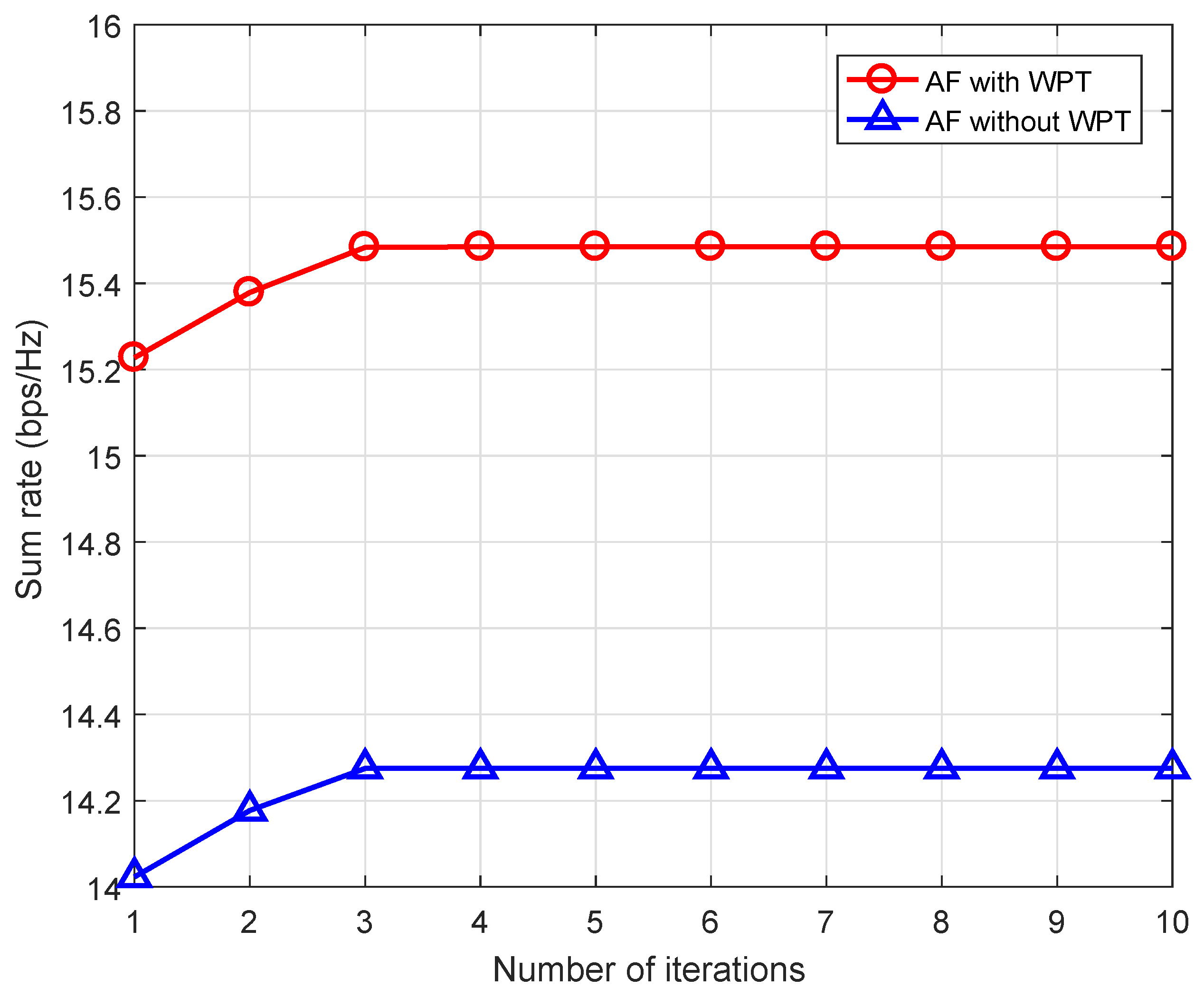
Figure 3.
Scenario 1 (): Average sum rate performance vs. time index (, and ).
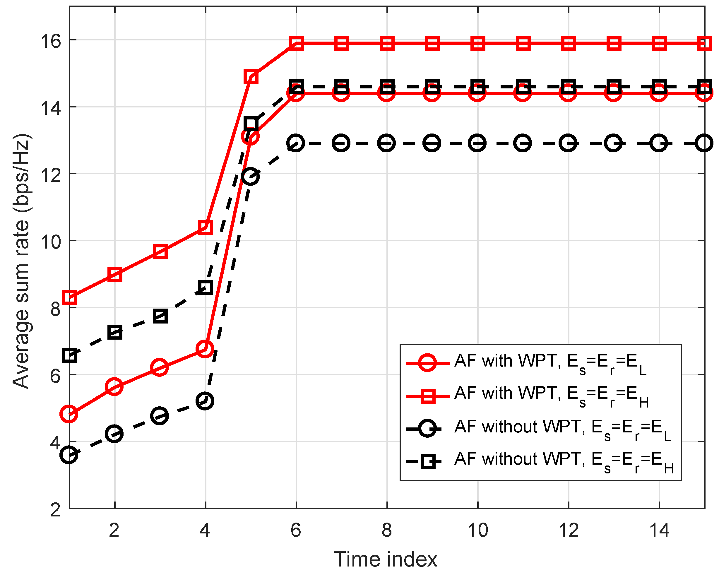
Figure 4.
Scenario 2 (): Average sum rate performance vs. time index (, and ).

Figure 5.
Average sum rate performance vs. time index when (, and ).

Figure 6.
Impact of the relay position on the average sum rate performance for different values of energy harvesting (EH) profiles with .
Figure 6.
Impact of the relay position on the average sum rate performance for different values of energy harvesting (EH) profiles with .

© 2019 by the authors. Licensee MDPI, Basel, Switzerland. This article is an open access article distributed under the terms and conditions of the Creative Commons Attribution (CC BY) license (http://creativecommons.org/licenses/by/4.0/).
Share and Cite
MDPI and ACS Style
Yadav, R.; Singh, K.; Biswas, S.; Kumar, A. Multi-User AF Relay Networks with Power Allocation and Transfer: A Joint Approach. Energies 2019, 12, 3157. https://doi.org/10.3390/en12163157
AMA Style
Yadav R, Singh K, Biswas S, Kumar A. Multi-User AF Relay Networks with Power Allocation and Transfer: A Joint Approach. Energies. 2019; 12(16):3157. https://doi.org/10.3390/en12163157
Chicago/Turabian StyleYadav, Ramnaresh, Keshav Singh, Sudip Biswas, and Ashwani Kumar. 2019. "Multi-User AF Relay Networks with Power Allocation and Transfer: A Joint Approach" Energies 12, no. 16: 3157. https://doi.org/10.3390/en12163157
Note that from the first issue of 2016, this journal uses article numbers instead of page numbers. See further details here.