An Improved Directional Relay Adapted to a Distribution Network with IIG Integration

1
State Key Laboratory of Alternate Electrical Power System with Renewable Energy Sources, North China Electric Power University, Beijing 102206, China
2
State Grid Tibet Electric Power Research Institute, Lhasa 850000, China
3
State Key Laboratory of Power Grid Safety and Energy Conservation, China Electric Power Research Institute Co., Ltd., Beijing 100192, China
*
Author to whom correspondence should be addressed.
Energies 2019, 12(17), 3345; https://doi.org/10.3390/en12173345
Submission received: 10 June 2019
/
Revised: 23 August 2019
/
Accepted: 26 August 2019
/
Published: 30 August 2019
(This article belongs to the Special Issue Integration of PV in Distribution Networks)
Abstract
:The integration of distributed generation (DG) into a distribution network changes the network’s topology. Three-stage current protection for a radial distribution network cannot meet the requirements of relay protection for a distribution network with DG. A directional relay that is based on the positive sequence fault component (PSFC) can effectively identify faults in the positive and negative directions and can be used to solve the adaptability problem with three-stage current protection in a multi-source distribution network. However, DG and the traditional generators have different fault characteristics and are affected by different control strategies, which may lower the sensitivity of a directional relay based on the PSFC or even cause mal-operation. Focusing on this problem, this paper proposes an improved directional relay that is adapted to a distribution network with inverter-interfaced generation (IIG) integration. The improved scheme divides the operation zone of the directional relay based on the PSFC into sensitive and insensitive areas. If the result of a phase comparison is located in the insensitive area, further identification is needed according to a comparison of the current amplitudes. Simulation experiments are carried out based on PSCAD/EMTDC, and their results verify the correctness of the proposed scheme.
1. Introduction
In recent years, with the development of distributed generation (DG) technology, DGs have become widely used in the distribution network. However, the integration of DGs into a distribution network changes the network’s topology from single-ended to double-ended or multi-ended. Therefore, the three-stage overcurrent protection, which is applied to the single-ended network, is not suitable for such scenarios [1,2,3,4,5,6].
To solve this problem, the traditional directional overcurrent protection (DOP), which utilizes the phase relationship between the voltage and the current to identify the direction of a fault, is proposed [7,8,9,10,11,12,13]. Reference [7] utilizes time-current characteristic curve (TCC) to improve the coordination of the overcurrent relay, but it still uses the traditional directional overcurrent protection to identify the fault direction. A DOP based on the cascade forward neural network (CFNN) is proposed in [8], however, the fault current characteristics of DGs are very complicated, if a fault has not been included in the training situations, the reliability of the relay may be affected. A DOP scheme based on the phase difference of the positive sequence component of the pre-fault and post-fault current is proposed in [9]. An adaptive DOP criterion by calculating the equivalent voltage and impedance is proposed in [10]. In addition, pilot protection based on the traditional DOP is proposed in [11,12]. Unfortunately, [9,10,11,12] do not consider the low-voltage ride through (LVRT) requirement of DGs. The traditional DOP may mal-operate in the cases of a wind farm increasing the reactive power output [13]. Reference [13] uses a load encroachment function as a solution, but the function does not consider the effect of high transition resistance. To summarize, problems with directional overcurrent protection may arise in the following two situations:
- A high-impedance ground fault, which may result in difficulties with identifying the direction of the fault;
- A change in the reactive power output of inverter-interfaced generators (IIGs), which may cause the mal-operation of the traditional directional overcurrent relay.
To improve the traditional directional overcurrent protection, the directional relay based on the positive sequence fault component (PSFC) has been widely used due to its ability to withstand transition resistance [14].
However, the fault characteristics of DGs are affected by the control strategies, which are different from conventional generators. The directional relay based on the PSFC is not suitable for the distribution network with IIG integration. In [15], the influence of IIGs on the directional relay based on the PSFC was analyzed. The authors pointed out that the phase angle of the equivalent positive sequence abrupt impedance (PSAI) of the IIG will vary from 0 to 180°, which may lower the sensitivity of the directional relay—or even cause its mal-operation. Unfortunately, no effective solution has been proposed yet.
In view of the low sensitivity or mal-operation of the directional relay based on the PSFC for a distribution network with IIGs, this paper proposes an improved directional relay. Compared with the directional relay based on the PSFC, two improvements are proposed in this paper:
- The operation zone is divided into a sensitive area and an insensitive area;
- An auxiliary criterion based on current amplitude comparison is added. If the result of the phase comparison is located in the insensitive area, then direction of the fault is further determined according to the result of the current amplitudes comparison.
This paper is organized as follows: the principle of the directional relay based on the PSFC and its adaptability in the distribution network with IIG integration is studied in Section 2. An improved directional relay based on an operation zone partition and a current amplitude comparison is proposed in Section 3. In Section 4, the correctness of the improved directional relay is verified by simulation. Section 5 concludes the paper.
2. The Principle of the Directional Relay Based on the PSFC and Its Adaptability
2.1. The Principle of the Directional Relay Based on the PSFC
The directional relay based on the PSFC identifies the direction of the fault according to the phase relationship between the fault voltage and current at the relay location [16].
Figure 1 shows the positive sequence fault additional network of a conventional double-ended power system. Supposing that an internal fault occurs and the IIG connects to the N-side, we take the N-side relay as an example.
The measured impedance of the N-side relay is:
where are the fault components of the positive sequence voltage , the post-fault positive sequence voltage, and the pre-fault positive sequence voltage, respectively; are the fault components of the positive sequence current, the post-fault positive sequence current, and the pre-fault positive sequence current, respectively; and is the equivalent impedance of the N-side system. Ignoring its resistance, the PSFC’s impedance angle at the N-side is:
It can be seen from Equation (2) that the maximum sensitivity angle of the directional relay based on the PSFC is −90°. Considering a certain margin, the criterion for identifying the positive direction of the relay is:
2.2. Control Strategy and Fault Characteristics of the IIG
The vector decoupling control method is usually adopted in IIGs, which generally directs the grid’s positive sequence voltage to the d-axis. The output power equation of the IIG is:
where the subscripts d and q represent the d-axis and q-axis component, respectively; and is the positive sequence voltage at the point of common coupling (PCC). Figure 2 shows a diagram of the vector decoupling control method.
Under normal circumstances, the IIG operates under a unit power factor, and adopts the double loop control strategy with an outer voltage loop and an inner current loop [17].
In the case of a fault, the IIG should possess a low-voltage ride through (LVRT) capability in order to meet the reactive power support requirements of the system. The reference values of the d-axis and q-axis currents and are shown in Equation (5):
where is the inverter’s maximum output current. The fault current provided by the IIG is influenced by the voltage sag and the control strategy, which is different from that used in a synchronous generator.
2.3. The Effect of IIG Fault Characteristics on the Directional Relay
Since the structure and the control method in IIGs are different from those of conventional synchronous generators, the fault characteristics are very complicated, which greatly affects the reliability of the conventional directional relay’s operation. Given that the grid-connected inverter of IIGs are nonlinear and the superposition principle cannot be used, it is necessary to define the equivalent positive-sequence abrupt impedance (PSAI) of the IIG (i.e., ) as shown in Equation (6):
where are the post-fault positive sequence voltage and the pre-fault positive sequence voltage at the outlet of the IIG, respectively; and are the post-fault positive sequence current and the pre-fault positive sequence current at the outlet of the IIG, respectively. The positive direction is from the busbar to the line, as shown in Figure 3.
Taking an internal fault as an example, when combined with Equation (2), the relationship between and is shown in Equation (7):
If the system is powered by a conventional double-ended source, is equal to the equivalent impedance of the backside system. If the phase angle of is 90°, according to Equation (7), the PSFC that is calculated from the relay location has an impedance angle of −90° at the maximum sensitivity angle. However, the fault characteristics of the IIG are affected by the control strategy—unlike conventional sources. The equivalent PSAI phase angle of the IIG may range between 0 and 180°. Under certain circumstances, may be very close to the boundary between the positive and negative operation zones, which may lower the sensitivity of the directional relay—or even cause mal-operation [15,16]. As a result, the phase angle of the equivalent PSAI is no longer 90°, and the performance of the directional relay based on the PSFC may be affected.
In the case of an asymmetric fault, the IIG usually adopts the control strategy of restraining the negative sequence current. The reference values of the active power and the reactive power are shown in Equation (8):
By using Park’s Transformation, the positive sequence fault current () at the outlet of the IIG can be expressed by the reference values of the d-axis current and the q-axis current , as shown in Equations (9) and (10):
In Equation (10), the subscript can represent phase A, phase B, or phase C (, , or ). Similar to Equations (9) and (10), the positive sequence fault voltage () at the outlet of the IIG is shown in Equations (11) and (12).
In Equation (11), is the drop coefficient of the positive sequence voltage; and is equal to zero because the positive sequence voltage is directed to the d-axis.
In the case of normal conditions, the IIG generally works under a unit power factor. Considering the abrupt phase angle of the positive sequence voltage, the pre-fault current () and the pre-fault voltage () are shown in Equation (13):
where is the ratio of load current to rated current; and is the abrupt angle of the positive sequence voltage. Substituting Equations (10), (12), and (13) into Equation (6), the expressions of the equivalent PSAI and the phase angle are shown in Equations (14) and (15), respectively:
Based on [15,18,19], the equivalent PSAI of the IIG is influenced by the control strategy, the fault condition, the load current, and so on. If can be ignored (, ), the simplified expression of the equivalent PSAI phase angle is shown in Equation (16):
According to the LVRT requirement, the IIG needs to provide reactive power to support the voltage [20], i.e., ; thus, is located at 0~180°. If , will decrease as decreases or increases, until is equal to 0°; if , will increase as increases or decreases, until is equal to 180°. When the IIG is integrated into an N-side system, the PSFC’s impedance angle that is calculated by the N-side relay will vary between −180° and ~0°. In addition, if cannot be ignored, Equation (15) is needed to analyze the phase angle of the PSAI. Analyses show that may be close to the boundary of the positive direction and the negative direction, which can greatly reduce the sensitivity of the directional relay or even cause its mal-operation.
In summary, the directional relay based on the PSFC only utilizes the phase comparison, which is liable to be affected by IIG integration in terms of sensitivity and reliability. Therefore, it is necessary to develop an improved directional relay that is suitable for the distribution network with IIG integration.
3. Improved Directional Relay Based on an Operation Zone Partition and a Current Amplitude Comparison
According to the analysis in Section 2.3, due to the low sensitivity—or even the mal-operation of the directional relay based on the PSFC—two improvements are proposed in this paper:
- The operation zone is divided into a sensitive area and an insensitive area (Section 3.1);
- An auxiliary criterion based on current amplitude comparison is added (Section 3.2). If the result of the phase comparison is located in the insensitive area, then the direction of the fault is further determined according to the result of the current amplitudes comparison.
3.1. Operation Zone Partition of the Directional Relay
3.1.1. The Sensitive Area (SA)
According to Equation (2), when a positive fault occurs, the maximum sensitivity angle of the directional relay based on the PSFC is −90°. As shown by the yellow shade in Figure 4, −135° was taken to approximately −45° as the sensitive area. If the result of the phase comparison is located in the sensitive area, i.e., , the directional relay can clearly identify that a positive fault has occurred.
3.1.2. The Insensitive Area (ISA)
The boundary between the positive and negative directions of the directional relay based on the PSFC is −180° and 0°. If a positive fault occurs at the outlet of the IIG, the measured phase angle may be located near the boundary. Considering a certain margin, the definition of the insensitive area is shown in terms of the green shade in Figure 4.
The sensitive area and the insensitive area together constitute the operation zone. If is outside the operation zone, the directional relay will identify that it is a negative fault. The definition of the negative direction area (NDA) is shown in Figure 4.
If the result of the phase comparison is located in the insensitive area, i.e., or , the directional relay cannot be sure that a positive fault has occurred. Thus, it is necessary to introduce an auxiliary criterion to further identify the direction of the fault.
3.2. Auxiliary Criterion for the Direction of a Fault Based on a Current Amplitude Comparison
When the result of the phase comparison is located in the insensitive area, mal-operation may occur due to low sensitivity, and the phase comparison will not be able to reliably identify the direction of the fault. Therefore, further identification is needed based on a comparison of the current amplitudes.
Taking the distribution system shown in Figure 5 as an example, we first choose the proper location where the IIG is integrated to guarantee that the minimum short-circuit current () that the equivalent system provides is greater than the maximum short-circuit current () that the IIG provides with a certain margin, as shown in Equation (17):
where k is the margin coefficient. k = 2 is adopted in this paper.
Relay 3 or 4, shown in Figure 5, is taken as an example in order to provide a detailed explanation.
According to the source which the fault current originated from, the relay can be divided into two categories: the system-side relay and the IIG-side relay. Taking the fault occurring at k1 in Figure 5 as an example, Relay 3 belongs to the system-side relay because the fault current flowing through Relay 3 is produced by the equivalent system power source G1. Whereas Relay 4 belongs to the IIG-side relay because the fault current flowing through Relay 4 is produced by the IIG.
If Equation (17) is satisfied, then can be set as the threshold. The direction of the short-circuit current can then be identified according to the following current amplitude comparison.
- If the short-circuit current at the relay location is greater than , then identify that the short-circuit current is provided by the conventional power source G1;
- If the short-circuit current at the relay location is smaller than , then identify that the short-circuit current is provided by the IIG.
Based on the above analysis, if the access point of the IIG is reasonably selected, the system-side and the IIG-side directional relays adopt different positive direction criteria, as shown in Equations (18) and (19), respectively, which can help to correctly discriminate the direction of the fault.
For the system-side relay (e.g., Relays 1 and 3), the positive fault should satisfy Equation (18):
For the IIG-side relay (e.g., Relays 2 and 4), the positive fault should satisfy Equation (19):
where is the measured current at the relay location; and is the maximum short-circuit current provided by the IIG.
3.3. Implementation of the Improved Directional Relay
According to the above analysis, IIG integration may lower the sensitivity of the directional relay based on the PSFC, or even cause its mal-operation. Therefore, we propose an improved directional relay based on a combination of the operation zone partition and the current amplitude comparison. The operation zone partition identifies where the result of the phase comparison is located (sensitive area, insensitive area and negative direction). When the result of the phase comparison is located in the insensitive area, the current amplitude comparison step is performed. The current amplitude is compared with the threshold to identify the direction of the fault.
Figure 6 shows the flow of the implementation of the improved directional relay. The steps in the process are as follows:
- Calculate the PSFC impedance angle at the relay location;
- If is outside the positive operation zone, the directional relay identifies that the fault has occurred in the negative direction;
- If is in the sensitive area, the directional relay identifies that the fault has occurred in the positive direction;
- If is in the insensitive area, perform the current amplitude comparison step. For system-side relay, if , the relay identifies that the fault has occurred in the positive direction; for IIG-side relay, if , the relay identifies that the fault has occurred in the positive direction. If the contrary is true, it identifies that the fault has occurred in the negative direction.
Taking the IIG-side’s Relay 4 as an example, the working principle of the improved directional relay is shown in Figure 6. The working principle of system-side relay is similar.
4. Simulation Analysis
In order to verify the correctness of the improved directional relay proposed in this paper, a simulation model of the distribution network with IIG integration was developed and is shown in Figure 5. The voltage level is 10 kV; the equivalent capacity of an external system with a traditional source is 100 MW; the IIG’s capacity is 1.5 MW; the length of lines L1, L2, L3, and L4 is 5 km; and the unit length impedance . In this paper, Relays 3 and 4 are taken as examples to study the performance of the proposed directional relay in various scenarios.
4.1. Performance of Proposed Directional Relay with IIG Access
To verify the correctness of the proposed directional relay, the PSCAD/EMTDC was utilized to simulate various scenarios. Section 4.1.1 and Section 4.1.2 show the results for the fault locations k1 (4 km away from busbar A) and k2 (1 km away from busbar B).
4.1.1. The Fault at k1
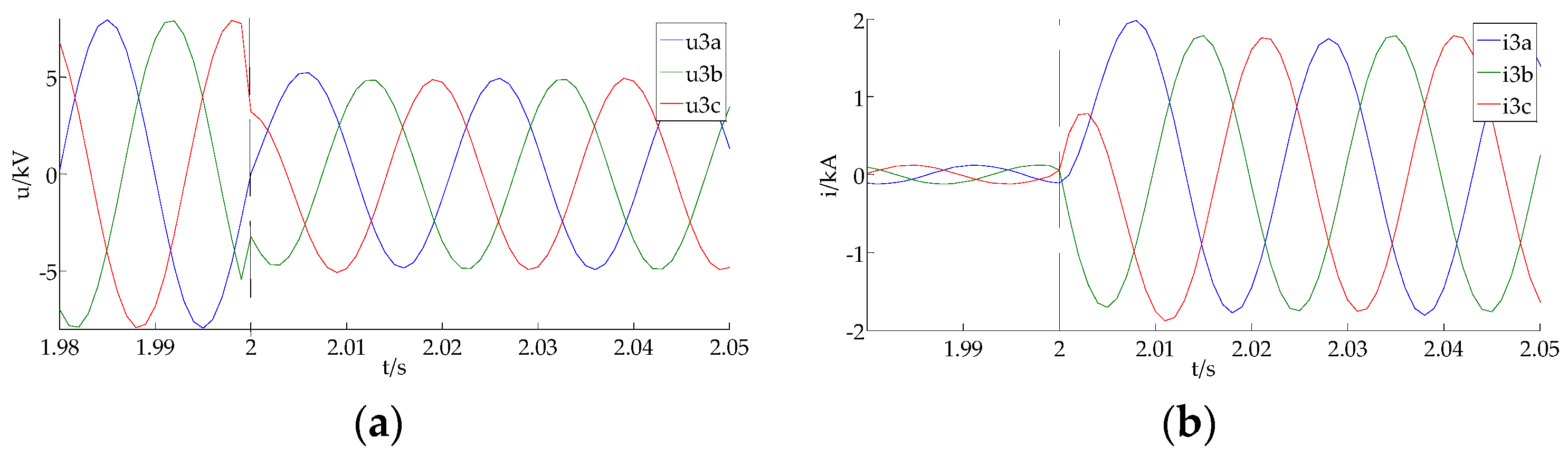
Taking a three-phase short circuit as an example, the voltage and current waveforms of Relays 3 and 4 are shown in Figure 7 and Figure 8, respectively.
Based on the symmetrical component method and using the Fourier algorithm, the PSFC’s voltage and current were extracted. The PSFC’s impedance angle at Relays 3 and 4 are −115° (sensitive area) and −157.6° (insensitive area), respectively. Therefore, Relay 3 identifies that a positive fault has occurred, and Relay 4 requires a current amplitude comparison. The root-mean-square (RMS) current of Relay 4 is 0.151 kA, which is less than the current threshold . Under these circumstances, Relay 4 belongs to the IIG side, and identifies that a positive fault has occurred according to Equation (19).
4.1.2. The Fault at k2
Taking a three-phase fault as an example, the voltage and current waveforms of Relays 3 and 4 are shown in Figure 9 and Figure 10, respectively.
The PSFC’s impedance angles at Relays 3 and 4 are −114° (sensitive area) and 65.85° (negative direction), respectively. Therefore, Relay 3 identifies that a positive fault has occurred, and Relay 4 identifies that a negative fault has occurred.
In addition, Table 1 lists the impedance phase angle and the short-circuit current amplitude under two-phase and two-phase to ground faults. “~” means that there is no need to compare the current amplitude; “SA”, marked by yellow shade, means the sensitive area; “ISA”, marked by green shade, means the insensitive area; “NDA” means the negative direction area; “+” denotes a positive fault; “−” denotes a negative fault; and the blue shade means that the fault current amplitude is smaller than .
As shown in Table 1, for the system-side Relay 3, when a fault occurs at k1 or k2, the PSFC’s impedance angle is located in the sensitive area, and the current amplitude comparison step is not needed. Thus, Relay 3 identifies that the fault occurs in the positive direction.
For the IIG-side Relay 4, when a fault occurs at k1, the PSFC’s impedance angle is located in the insensitive area, and the current amplitude comparison step is needed. Since the current of Relay 4 is less than , Relay 4 identifies that the fault occurs in the positive direction. When a fault occurs at k2, the PSFC’s impedance angle is located in the negative direction and can be directly judged as a negative fault. The above-presented results of direction of the fault are consistent with the actual situation.
4.2. Advantages over the Directional Relay Based on the PSFC
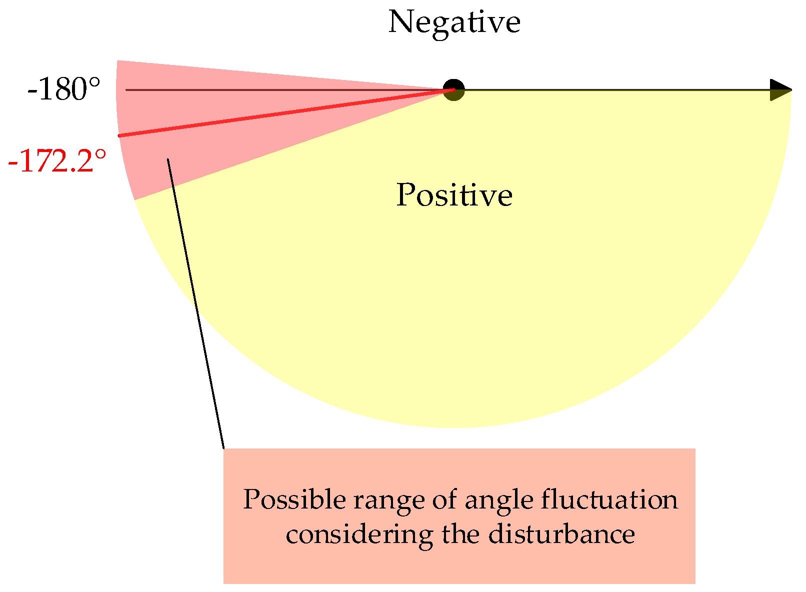
In order to explain the advantages the improved directional relay compared with the directional relay based on the PSFC had, a special case is taken into consideration. Suppose no load current in the network under normal operation as shown in Figure 5, a three-phase fault occurs at k3 (the end of line L2), the calculated angle of the directional relay based on the PSFC at Relay 4 is −172.2°, which approaches to the operating boundary of the directional relay as shown in Figure 11.
It can be seen from Figure 11 that the sensitivity of directional relay based on PSFC is very low under such a scenario. Considering the measurement error and disturbance, the calculated angle of the directional relay based on the PSFC may be less than −180°, and the directional relay based on PSFC will not operate.
Compared with the directional relay based on the PSFC, the improved directional relay proposed in this paper can operate accurately under the same scenario. The reasons are given below: −172.2° locates in the insensitive area, according to Figure 4. Considering the measurement error and disturbance, the calculated angle may vibrate around −180°, thus the auxiliary criterion based on current amplitude comparison is needed. The root mean square (RMS) of measuring current at relay 4 is 0.144kA, which is smaller than the current threshold , therefore, a positive fault can be clearly identified by Relay 4 according to Figure 6.
In summary, for system-side relay, the directional relay based on the PSFC is normally able to accurately identify the direction of the fault, and is more sensitive to positive faults. When a positive fault occurs for IIG-side relay, the PSFC’s impedance angle may be located in the insensitive area. The sensitivity of the conventional directional relay based on the PSFC is lowered, and the fault can be accurately identified by the auxiliary criterion, based on the current amplitude comparison.
In fact, a distribution network normally has multiple IIGs integrated into it. A further series of simulations showed that the directional relay proposed in this paper is applicable in such a scenario as well.
5. Conclusions
The fault characteristics in IIGs are different from those in a conventional synchronous generator, which may lower the sensitivity of the directional relay based on the PSFC—or even cause its mal-operation. Focusing on this problem, this paper proposes an improved directional relay which is adapted to a distribution network with IIG integration. The improved directional relay divides the operation zone of the directional relay into a sensitive area and an insensitive area. If the result of the phase comparison is located in the insensitive area, a further identification is performed according to a current amplitude comparison, which enables the directional relay to accurately identify the direction of the fault. Based on PSCAD/EMTDC simulations, we draw the following conclusions:
- For system-side relay, the directional relay based on the PSFC can accurately identify the direction of the fault and has higher sensitivity to positive faults.
- For IIG-side relay, the impedance angle of the PSFC may be located in the insensitive area, and the sensitivity of the directional relay based on the PSFC may be lowered. However, the application of the current amplitude comparison enables the relay to accurately identify the direction of the fault.
Author Contributions
All authors (Y.Z., T.Z., M.W., H.Z., and X.W.) contributed to the preparation of the manuscript. Conceptualization, T.Z.; formal analysis, Y.Z.; methodology, M.W.; supervision, H.Z.; project administration, X.W.; writing—original draft, Y.Z.; writing—review and editing, Y.Z. and T.Z.
Funding
This research was funded by the Key Project of Smart Grid Technology and Equipment of the National Key Research and Development Plan of China, grant No. 2016YFB0900600, and Research on the Adaptability of Tibet Power Grid Protection after Large-scale Intermittent New Energy Access and Grid Interconnection.
Conflicts of Interest
The authors declare no conflicts of interest.
References
- Liu, J.; Lin, T.; Tong, X.Q.; Li, L.; Zhang, Z. Simulation analysis on influences of distributed photovoltaic generation on short-circuit current in distribution network. Power Syst. Technol. 2013, 37, 2080–2085. [Google Scholar]
- Tan, H.; Li, Y.; Chen, X. Influence of inverter-interfaced distributed generator with low-voltage ride-through capability on short circuit current of distribution network. Electr. Power Autom. Equip. 2015, 35, 31–37. [Google Scholar]
- Manditereza, P.T.; Bansal, R. Renewable distributed generation: The hidden challenges—A review from the protection perspective. Renew. Sustain. Energy Rev. 2016, 58, 1457–1465. [Google Scholar] [CrossRef]
- Bi, T.; Liu, S.; Xue, A.; Yang, Q. Fault Characteristics of Inverter-interfaced Renewable Energy Sources. Proc. CSEE 2013, 33, 165–171. [Google Scholar]
- Pan, G.; Zeng, D.; Wang, G.; Zhu, G.L.; Li, H.F. Fault analysis on distribution network with inverter interfaced distributed generations based on PQ control strategy. Proc. CSEE 2014, 34, 555–561. [Google Scholar]
- Plet, C.A.; Brucoli, M.; McDonald, J.D.; Green, T.C. Fault models of inverter-interfaced distributed generators: Experimental verification and application to fault analysis. In Proceedings of the IEEE Power and Energy Society General Meeting, Detroit, MI, USA, 24–29 July 2011. [Google Scholar]
- Sahrin, A.; Tjahjono, A.; Pujiantara, M.; Purnomo, M.H. The modeling of directional overcurrent relay in loop system using cascade forward neural network. In Proceedings of the 2017 International Seminar on Intelligent Technology and Its Applications (ISITIA), Surabaya, Indonesia, 28–29 August 2017. [Google Scholar]
- Farkhani, J.S.; Zareein, M.; Soroushmehr, H.; SIEEE, H.M. Coordination of Directional Overcurrent Protection Relay for Distribution Network with Embedded DG. In Proceedings of the 2019 5th Conference on KBEI, Tehran, Iran, 13 June 2019. [Google Scholar]
- Zhu, L.L.; Li, C.K.; Zhang, H.Z.; Zhou, P.Y. Directional overcurrent protection for distribution systems containing distributed generation. Power Syst. Technol. 2009, 33, 94–98. [Google Scholar]
- Ma, J.; Liu, J. Adaptive directional current protection scheme based on steady state component in distribution network with DG. Electr. Power Autom. Equip. 2018, 38, 1–9. [Google Scholar] [CrossRef]
- Alvin, T.G.; Abidin, I.Z.; Hashim, H.; Abidin, A.Z. Phase comparison protection for distribution networks with high PV penetration. In Proceedings of the 2014 IEEE Innovative Smart Grid Technologies—Asia (ISGT ASIA), Kuala Lumpur, Malaysia, 20–23 May 2014. [Google Scholar]
- Jingliao, S.U.N.; Yongli, L.I.; Shengwei, L.I.; Qiang, J.I.N. A protection scheme for distribution system with distributed generations. Autom. Electr. Power Syst. 2009, 33, 81–84. [Google Scholar]
- Jones, D.; Bennet, K. Wind Farm Collector Protection Using Directional Overcurrent Elements; PES T&D: Orlando, FL, USA, 7–10 May 2012. [Google Scholar]
- Gao, H.; Crossley, P.A. Directional relay for EHV transmission lines using positive sequence fault components. In Proceedings of the 2005 IEEE Russia Power Tech, St. Petersburg, Russia, 27–30 June 2005. [Google Scholar]
- Jia, K.; Zhe, Y.; Fang, Y.; Bi, T.; Sumner, M. Influence mechanism of inverter-interfaced renewable energy generators on fault component based directional relay. Power Syst. Technol. 2017, 41, 3230–3236. [Google Scholar]
- Huang, T.; Lu, Y.; Cai, C. Analysis of phase angle characteristics of DFIG equivalent sequence superimposed impedances and its impact on fault components based directional relay. Proc. CSEE 2016, 36, 3929–3940. [Google Scholar]
- Liu, H.; Xu, K.; Zhang, Z.; Liu, W.; Ao, J. Research on Theoretical Calculation Methods of Photovoltaic Power Short-Circuit Current and Influencing Factors of Its Fault Characteristics. Energies 2019, 12, 316. [Google Scholar] [CrossRef]
- Jin, W.; Lu, Y.; Huang, T. Improved Blocking Scheme for CPL Current Protection in Wind Farms Using the Amplitude Ratio and Phase Difference. IEEE Access 2019, 7, 68060–68070. [Google Scholar] [CrossRef]
- Xu, G.; Liang, Y.; Zha, W.; Huo, Y.; Qin, X.; Wang, C. Adaptability Analysis of Directional Relay for Transmission Line Out-sending from Photovoltaic Power Plant. Power Syst. Technol. 2019, 43, 1632–1639. [Google Scholar]
- GB/T 19964-2012, Technical Regulations for Photovoltaic Power Stations Accessing to Power Systems; General Administration of Quality Supervision, Inspection and Quarantine of the People’s Republic of China; Standardization Administration of the People’s Republic of China: Beijing, China.
Figure 1.
The traditional double-ended power system: (a) a diagram of the traditional double-ended power system; (b) the positive sequence fault additional network.
Figure 1.
The traditional double-ended power system: (a) a diagram of the traditional double-ended power system; (b) the positive sequence fault additional network.
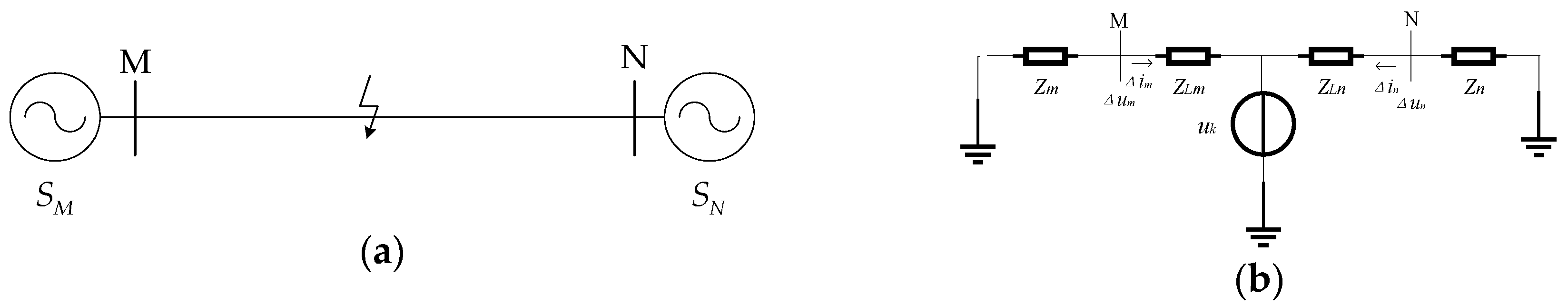
Figure 2.
A diagram of the vector decoupling control method.
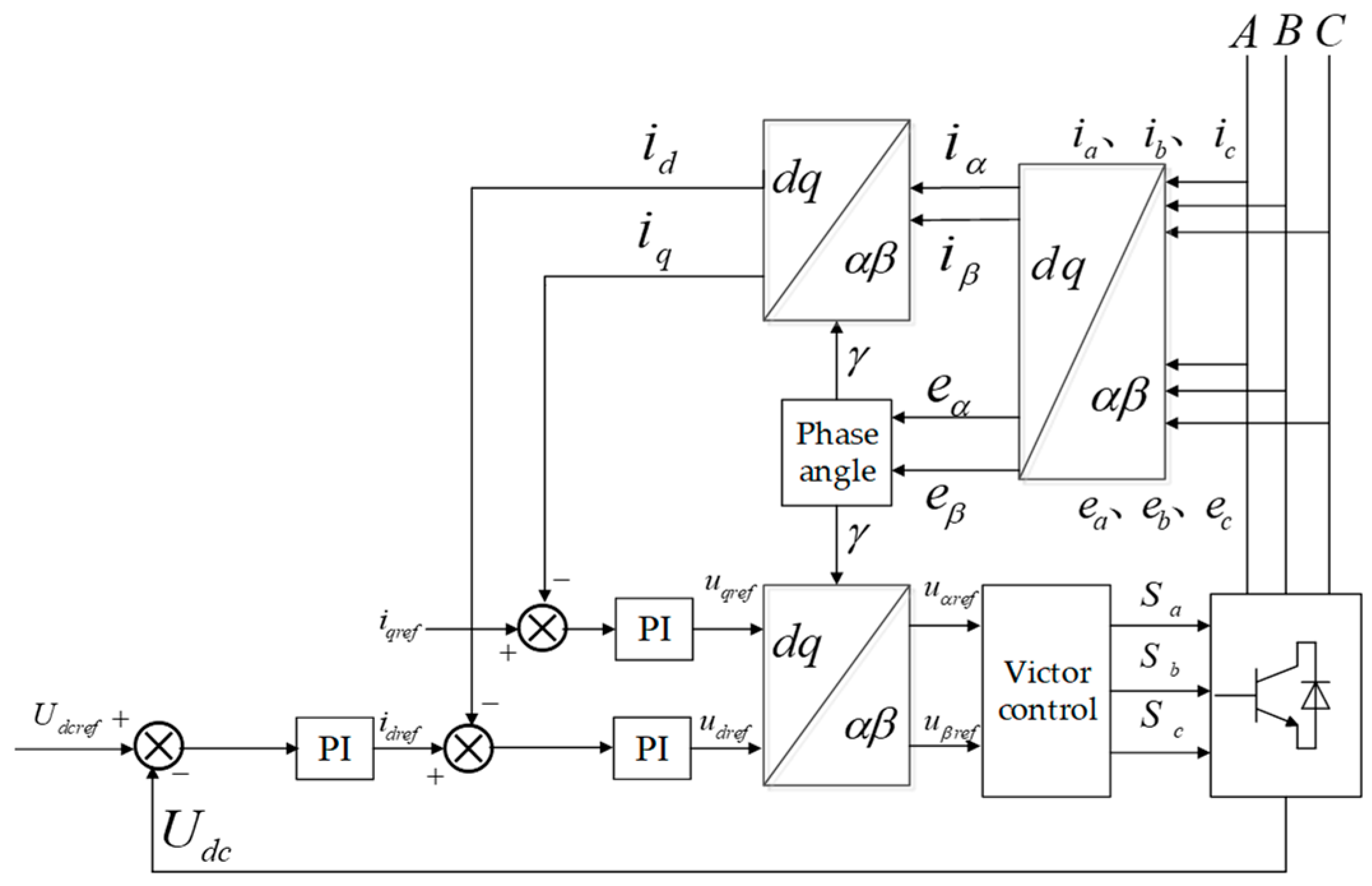
Figure 3.
Topology of an inverter-interfaced generator (IIG).
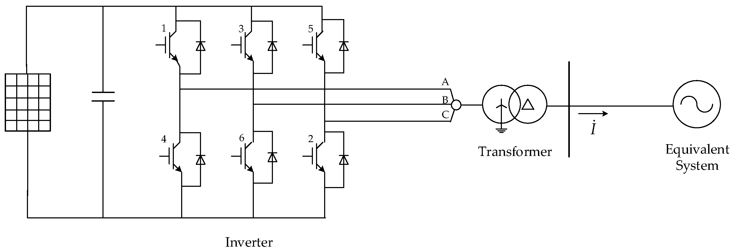
Figure 4.
The sensitive area and the insensitive area.
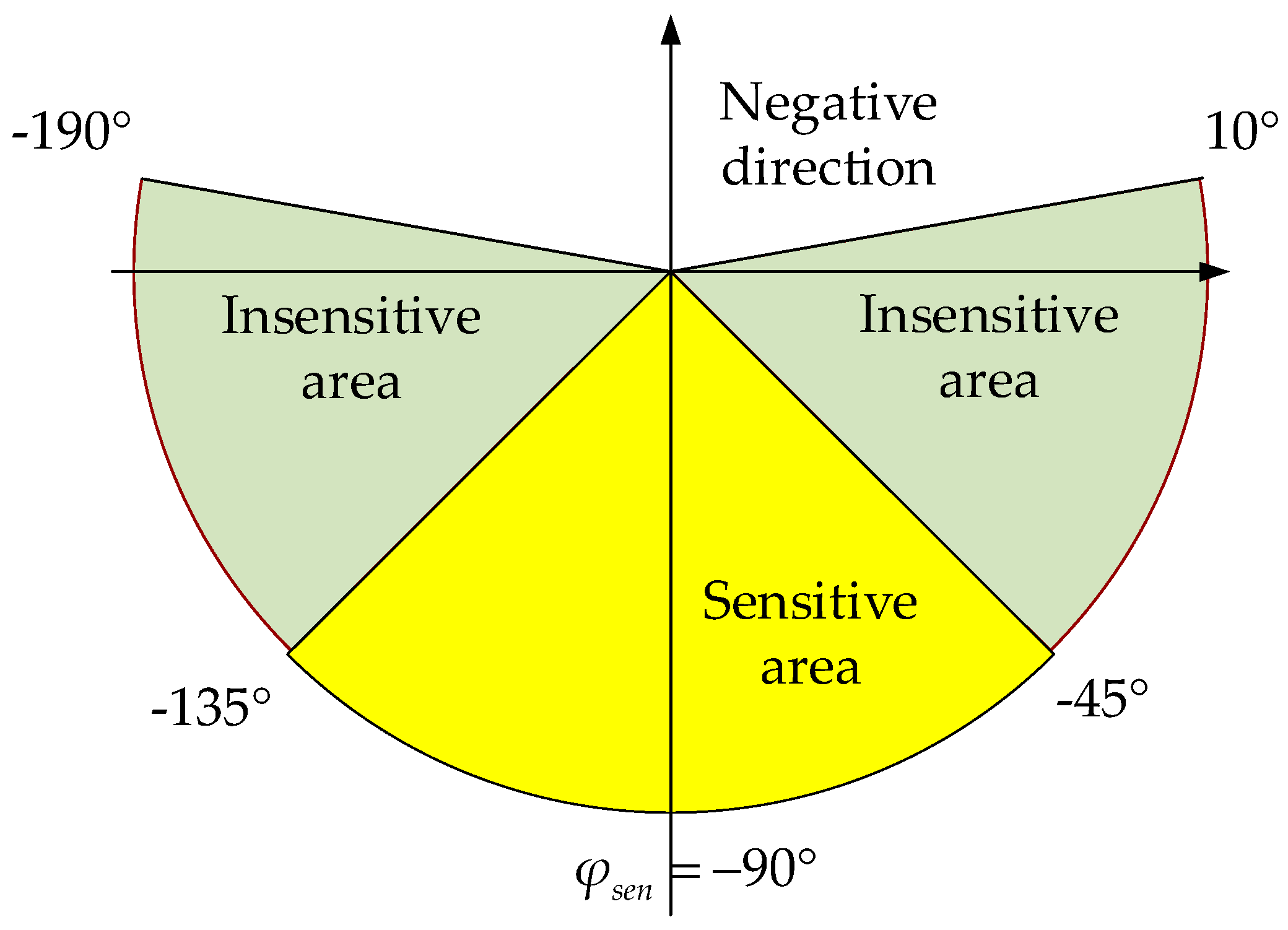
Figure 5.
A diagram of the distribution network with IIG integration.
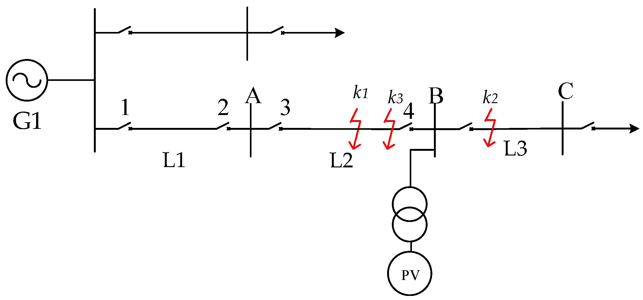
Figure 6.
Flow chart of the improved directional relay.
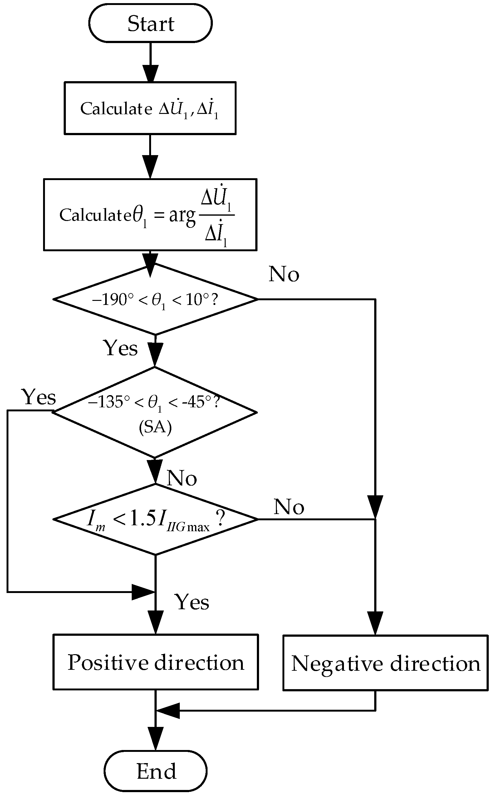
Figure 7.
Voltage and current waveforms of Relay 3 during a three-phase fault at k1: (a) voltage; (b) current.
Figure 7.
Voltage and current waveforms of Relay 3 during a three-phase fault at k1: (a) voltage; (b) current.

Figure 8.
Voltage and current waveforms of Relay 4 during a three-phase fault at k1: (a) voltage; (b) current.
Figure 8.
Voltage and current waveforms of Relay 4 during a three-phase fault at k1: (a) voltage; (b) current.

Figure 9.
Voltage and current waveforms of Relay 3 during a three-phase fault at k2: (a) voltage; (b) current.
Figure 9.
Voltage and current waveforms of Relay 3 during a three-phase fault at k2: (a) voltage; (b) current.
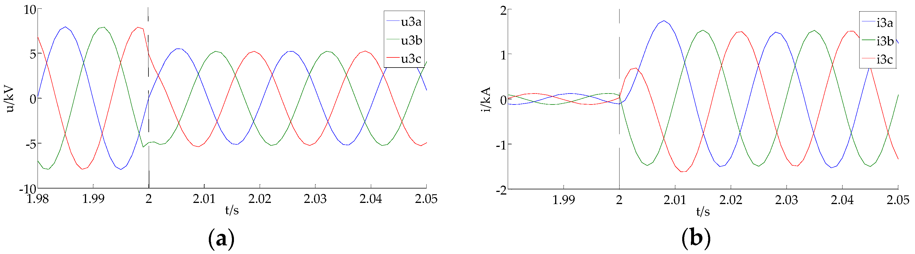
Figure 10.
Voltage and current waveforms of Relay 4 during a three-phase fault at k2: (a) voltage; (b) current.
Figure 10.
Voltage and current waveforms of Relay 4 during a three-phase fault at k2: (a) voltage; (b) current.
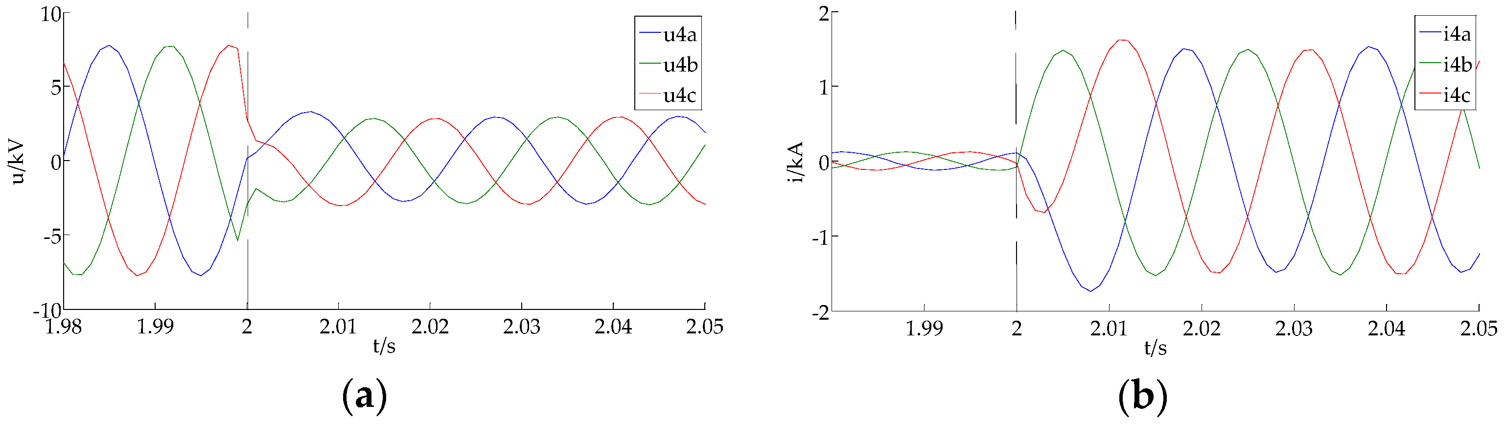
Figure 11.
The calculated angle of the directional relay based on the PSFC.

Table 1.
Relay identification results when faults occur at different locations.
| Fault Location | Fault Type | Relay 3 | Relay 4 | ||||||
|---|---|---|---|---|---|---|---|---|---|
| Fault Current Amplitude/kA | Identification Result | Fault Current Amplitude/kA | Identification Result | ||||||
| k1 | 3ph | −115° | SA | ~ | + | −157.6° | ISA | ) | + |
| 2ph | −113.2° | SA | ~ | + | −153.4° | ISA | ) | + | |
| 2ph-g | −109.7° | SA | ~ | + | −142.7° | ISA | ) | + | |
| k2 | 3ph | −114° | SA | ~ | + | 65.85° | NDA | ~ | - |
| 2ph | −115.1° | SA | ~ | + | 64.64° | NDA | ~ | - | |
| 2ph-g | −111° | SA | ~ | + | 68.79° | NDA | ~ | - | |
© 2019 by the authors. Licensee MDPI, Basel, Switzerland. This article is an open access article distributed under the terms and conditions of the Creative Commons Attribution (CC BY) license (http://creativecommons.org/licenses/by/4.0/).
Share and Cite
MDPI and ACS Style
Zhu, Y.; Zheng, T.; Wang, M.; Zhao, H.; Wang, X. An Improved Directional Relay Adapted to a Distribution Network with IIG Integration. Energies 2019, 12, 3345. https://doi.org/10.3390/en12173345
AMA Style
Zhu Y, Zheng T, Wang M, Zhao H, Wang X. An Improved Directional Relay Adapted to a Distribution Network with IIG Integration. Energies. 2019; 12(17):3345. https://doi.org/10.3390/en12173345
Chicago/Turabian StyleZhu, Yifan, Tao Zheng, Minghao Wang, Hongcheng Zhao, and Xingguo Wang. 2019. "An Improved Directional Relay Adapted to a Distribution Network with IIG Integration" Energies 12, no. 17: 3345. https://doi.org/10.3390/en12173345
Note that from the first issue of 2016, this journal uses article numbers instead of page numbers. See further details here.