Article

Performance Analysis of a Small-Scale Biogas-Based Trigeneration Plant: An Absorption Refrigeration System Integrated to an Externally Fired Microturbine

by
J. Villarroel-Schneider
1,2,*,
Anders Malmquist
1,
Joseph A. Araoz
2,
J. Martí-Herrero
3,4 and
Andrew Martin
1
1
Department of Energy Technology, School of Industrial Technology and Management (ITM), KTH Royal Institute of Technology, SE-100 44 Stockholm, Sweden
2
Facultad de Ciencias y Tecnología (FCyT), Universidad Mayor de San Simón (UMSS), Cochabamba 2500, Bolivia
3
Biomass to Resources Group, Universidad Regional Amazónica Ikiam, Tena 150156, Ecuador
4
Building Energy and Environment Group, Centre Internacional de Mètodes Numèrics en Enginyeria (CIMNE), Edifici GAIA (TR14), C/Rambla Sant Nebridi. 22, 08222 Terrassa, Barcelona, Spain
*
Author to whom correspondence should be addressed.
Energies 2019, 12(20), 3830; https://doi.org/10.3390/en12203830
Submission received: 29 July 2019 / Revised: 2 October 2019 / Accepted: 2 October 2019 / Published: 10 October 2019
(This article belongs to the Special Issue Production and Utilization of Biogas)

Abstract

:
Trigeneration or combined cooling, heat and power (CCHP) systems fueled by raw biogas can be an interesting alternative for supplying electricity and thermal services in remote rural areas where biogas can be produced without requiring sophisticated equipment. In this sense, this study considers a performance analysis of a novel small-scale CCHP system where a biogas-fired, 5 kWel externally fired microturbine (EFMT), an absorption refrigeration system (ARS) and heat exchangers are integrated for supplying electricity, refrigeration and hot water demanded by Bolivian small dairy farms. The CCHP solution presents two cases, current and nominal states, in which experimental and design data of the EFMT performance were considered, respectively. The primary energy/exergy rate was used as a performance indicator. The proposed cases show better energy performances than those of reference fossil fuel-based energy solutions (where energy services are produced separately) allowing savings in primary energy utilization of up to 31%. Furthermore, improvements in electric efficiency of the EFMT and coefficient of performance (COP) of the ARS, identified as key variables of the system, allow primary energy savings of up to 37%. However, to achieve these values in real conditions, more research and development of the technologies involved is required, especially for the EFMT.

Graphical Abstract

1. Introduction

The demand for refrigeration and air conditioning is constantly increasing due to its importance in the food/medicine industry, commercial activities, health centers and domestic uses. According to the International Refrigeration Institute (IIR) around 17% of the electricity supplied worldwide is required to meet the demand of these services [1]. Refrigeration is especially important for food preservation; however, the access to this service in remote and rural areas is still limited mainly due to the lack of electricity that does not allow the use of conventional compressor driven refrigeration systems. In this scenario, an absorption refrigeration system (or absorption chiller), which requires a heat source for its operation [2], could be a solution. This system is an appropriate option when: (i) There is availability of a heat source (combustion gas, geothermal or solar heat) and (ii) the refrigeration requirement is important while the availability of electricity is limited/inexistent or expensive [3], as in many rural areas. Considering this, a power generator, heat recovery units and an absorption refrigeration system are ideal for forming a combined cooling, heat and power plant (CCHP or trigeneration) [4,5], which allows supplying the required energy services.
The simultaneous production of electricity and thermal services in remote rural areas is a challenge. Most of the existing combined energy solutions demand the use of fossil fuels (e.g., natural gas, LPG, diesel) or fuels that require cleaning and compression processes of the gas (e.g., biogas for microturbines and some internal combustion engines). Unfortunately, in many rural areas the access to fossil fuels and equipment for cleaning and compressing is limited due to several reasons. In this scenario, the externally fired microturbine (EFMT) has an interesting application potential, due to its flexibility in terms of the use of fuels. This microturbine can run with raw fuels such biomass syngas and biogas, without requiring a strict pre-treatment [6,7]. The EFMT also does not require a gas compressor since the combustion takes place at atmospheric pressure. Other heat sources can also be utilized, including solar and direct burning of biomass [7]. Therefore, this microturbine is perfectly suitable in rural areas where, for example, biogas can be used without requiring expensive and sophisticated equipment for its production. However, this especial feature of the EFMT shows that further research for its development and for exploring its applications in decentralized energy solutions is required. In this regard, proposing a new combined energy system will need an integrated evaluation. An energy/exergy performance analysis of this EFMT as the main component of a CCHP system is a logical first step for such evaluation. This will allow (i) determining if the proposed CCHP system is more efficient in front of fossil-fuel-based solutions and (ii) identifying the elements that have more influence on the overall performance of the system.
Previous reviews [8,9,10,11] on CCHP systems have considered prime movers such as internal combustion engines, Stirling engines, steam turbines, gas turbines, internally fired microturbines (IFMT) and fuel cells. However, in these publications the externally fired microturbine (EFMT) was not mentioned. Recently, in 2018, Wegener et al. [5] presented a complete review of biomass-fired CCHP for small-scale applications. In this study, the EFMT is highlighted because of its capability to work with low quality fuels; however, not CCHP applications with this microturbine were mentioned. These reviews show that studies of such turbines integrated in CCHP systems are probably non-existent (at least up to the year of publication of the last review—2018). Previous research on combined energy systems focused on: Evaluating their thermodynamic performance [12,13,14,15,16,17,18], techno-economic/environmental feasibility [19,20,21,22,23], integrated evaluation of CCHP solutions [24,25], defining configuration/operating strategies [26,27,28,29,30] and prime mover selection criteria for CCHP solutions [31,32]. Furthermore, the majority of these studies focus on applications in power plants integrated with district heating/cooling systems, high refrigeration demands (in supermarkets) and in air conditioning systems for offices and apartment buildings without considering small-scale applications in remote rural areas. None of these studies considered (or explicitly mentioned) the externally fired microturbine. It seems that the main reason is that the EFMT technology is still under development; its presence in the market is almost non-existent (especially for small microturbines) and, therefore, there are no proposed/studied applications using this microturbine.
Few studies that consider the use of biogas as fuel in combined energy systems were found. Khan et al. [33] have presented a techno-economic analysis of a small-scale polygeneration system applied in a rural village located in Bangladesh using biogas (from cow dung) to supply electricity, biogas (for cooking), fertilizer and clean water (via heat driven membrane distillation). The prime mover proposed was an internal combustion engine. The results show that this solution can be a good alternative in terms of economic and social benefits. Other studies [27,34] have focused in the use of CCHP (trigeneration) systems using biogas produced in landfills and sewage treatment plants where IFMT is considered. The Capstone C30 [35] microturbine is often considered for these studies.
The EFMT was mostly studied as the prime mover in cogeneration systems (combined heat and power—CHP) mostly considering the use of biomass gasification gas, biomass direct firing or thermo-solar energy as a source of heat. Most of the investigations are based on EFMT in a range around 100 kWel. One of these turbines is commercialized as the T100 model from Turbec [36,37,38], in its externally fired version (nowadays, the T100 is produced by Ansaldo). The studies are mainly focused on the influence of the high temperature heat exchanger (HTHE) characteristics (efficiency, temperatures, pressure drops and material) on the microturbine performance [39], the use of low-calorific biogas [40] and the integration of sub-systems to provide additional energy services, for example, a biomass dryer [41]. The high temperature heat exchanger is considered as a key element of the EFMT; it serves to transfer the heat from the combustion gas to a clean/compressed flow of air that is expanded in the turbine. Baina et al. [6] presented an evaluation of the effect of the fuel type on the performance of an externally fired micro gas turbine. The EFMT under that study was a prototype named ET10 from Compower AB [42]. For the testing, a simulated biogas mixture of 35% CO2 and 65% CH4 volume/volume (v/v) was employed [6].

1.1. Biogas and the Advantages of Its Use in an Externally Fired Microturbine

Biogas can be compared to natural gas, when a treatment to clean and increase its methane content is included [43]. On the market there are engines and turbines that have been developed to work with biogas as a fuel [8,9], for example, internally fired microturbines [44], as well as internal combustion engines [45]. However, biogas is produced at low pressure, and thus a gas compressor is usually needed to reach the high pressure that is required in the combustion chamber of a gas turbine. Moreover, the raw biogas produced in small plants without a strict cleaning process cannot be used for long term operation in internally fired engines and turbines because of contaminants and particles in the combustion gas [6] that damage the internal parts of these devices.
One of the advantages of using biogas in externally fired gas turbines (EFMT) is that it is not required to be extremely clean and highly compressed. The EFMT can work with fuels that have a reduced lower heating value (LHV) and low quality in terms of purity. In EFMTs, the combustion process takes place at atmospheric pressure outside of the turbine cycle, whereafter the flue gas goes to a high temperature heat exchanger (HTHE), which is less sensitive to contaminants. Thus it is not harmful for the mechanical rotating parts of the turbine since the flue gas (resulting from the combustion of biogas) is not directly in contact with the turbine [7].
The features of the EFMT and the use of biogas (without strict treatment) make this solution perfectly suitable in rural areas, for example, when using biogas produced in low-cost tubular biodigesters, such as those proposed and implemented in Bolivia [46,47,48,49]. However, the use of low cost biodigesters should not limit a constant flow of biogas according to the requirement of the microturbine. This will probably require the installation of more than one biodigester and a low-pressure biogas storage system. The production of biogas can meet not only the fuel demand for power generation but also for cooking purposes. An additional service resulting from biogas production is bio-slurry which is a natural fertilizer very much required in agriculture [49,50]. Therefore, the production and use of biogas allows avoiding/reducing the consumption of fossil fuels and chemical fertilizers while supplying various energy services.

1.2. Thermal Demands for Small-Scale Applications in Bolivian Dairy Farms

Fieldwork for data collection and surveys was carried out in small dairy farms located in central Bolivia (in Appendix A the fieldwork carried out and the information obtained are described). The following relevant information about their current conventional refrigeration systems was obtained:
  • The required cooling capacity for milk storage in tanks is between 6 and 14 kWth.
  • The recommended temperature for milk storage is 4 °C.
  • The coefficient of performance (COP) of current compressor driven refrigeration systems is between 2 and 4.
  • The capacities of the milk tanks are between 1100 and 2000 L.
Besides refrigeration, access to hot water for cleaning purposes in farms is another important need; the water must have a temperature of at least 55 °C [51]. Currently hot water is supplied by using water heaters or common stoves, both powered by liquefied petroleum gas (LPG). LPG is available for sale in small tanks and is accessible in the area where the fieldwork was carried out.
The reviewed literature shows that there are no previous studies that specifically analyze the performance of a biogas-based trigeneration (CCHP) system for small-scale applications where the EFMT is the prime mover. To fill this gap in the research, the objective of this study is to propose a new biogas-based trigeneration system and analyze its overall energy performance considering the advantages of the use of biogas in an EFMT and the small demands for energy services existing in rural areas (as in the case of Bolivian small dairy farms). This solution has a high potential for rural applications, for example in typical small farms located in impoverished countries where the access to high quality fuels is difficult. The proposed trigeneration solution consists in the integration of an absorption refrigeration system (ARS) and heat recovery units to the EFMT. This solution is proposed to supply the energy demands of Bolivian small-scale dairy farms, electricity, refrigeration (for milk preservation) and hot water (for cleaning tasks). The energy source considered for the system is biogas, which can be produced with farm waste (cow dung) through anaerobic digestion. This work does not consider a detailed study of the conditions and characteristics of biogas production but emphasizes its potential for use in alternative energy solutions that allows reducing the dependence on fossil fuels while enhancing the access to energy services in remote rural areas.
The EFMT considered in this study is the ET10 microturbine prototype from Compower AB [42], while the ARS is the Pink Chiller PC19, which is commercially available [52]. Two cases for the CCHP system are presented: The first (current state), takes into account the EFMT performance achieved during the experimental tests carried out at KTH Royal Institute of Technology; the second (nominal state) considers the performance for which the microturbine was designed, as provided by the manufacturer (Compower AB, Sweden). The energetic and exergetic performances of the CCHP solution are determined using the primary energy/exergy rate ( P E R and P E R x ) indicator. These performances are compared to those of reference fossil fuel-based energy systems (current technologies used in the dairy farms). A performance analysis for enhanced configurations, assuming improvements in the COP of the absorption refrigeration system, and in the electrical efficiency of the EFMT prototype (identified as key parameters) is also included. Finally, energy saving rates generated with the proposed solutions, when compared to the reference systems (fossil fuel-based solutions), are determined.
The rest of the paper is structured as follows: Section 2 contains the methodology that has been applied to carry out this study. The results are presented and discussed in Section 3 while the main conclusions are drawn in Section 4.

2. Methodology

The methodology to address the research gap presented in this study considers several steps, but focuses on two main tasks: Determining the performances of a proposed CCHP system (in its different variations) and verifying whether these performances are better than those of conventional fossil fuel-based solutions (allowing savings in primary energy). However, the evaluation of the performance of a trigeneration system, which supplies electricity and thermal services (such as heating and cooling) simultaneously, is complex and can be approached in different ways. This complexity is mainly due to the various energy sources that can be used in a CCHP system and the various forms of energy services that can be supplied [53], in addition to the diversity of energy conversion devices that can interact bidirectionally, it means as consumer/producer for the case of systems integrated to electrical and/or thermal grids [54]. Despite this, some authors have agreed that the appropriate indicators to determine the performance of trigeneration systems are the primary energy rate ( P E R ) and the energy saving rate ( Δ eS ) [53,54,55], which are adopted in this study (where it is also included the primary exergy rate, P E R x , which is applied analogously that the P E R ). The first indicator allows determining the degree of exploitation of the primary energy source, while the second allows determining the proportion of primary energy savings that would be achieved with the use of the proposed systems (when compared to the conventional fossil fuel-based solutions, where the energy services are produced separately).
Considering this, the performance of the proposed CCHP system was compared with those of the reference (conventional fossil fuel-based) solutions. For the purposes of this study, it is assumed that the CCHP operates at two different states (current and nominal), which depend on the microturbine (EFMT) operation. The current state refers to the current microturbine performance, measured at lab conditions. The nominal corresponds to the microturbine performance obtained at the design conditions. The following steps were followed:
  • Estimation of energy service demands required in small dairy farms. A description of the data collected (in the fieldwork) for estimating the energy services demands.
  • Analysis for the operation and main characteristics of the proposed CCHP solution. This includes the description of the different components, the technical requirements for their integration (ARS, EFMT and heat exchangers) and their operation parameters.
  • Simulations of the CCHP system variations using “Aspen Hysys V8.4”. This was performed to determine the power output and the thermal potential of the combustion gas (of the EFMT) to supply the demanded thermal services. In addition, the integration of the different components was evaluated through these simulations.
  • The overall efficiency of the CCHP solution was calculated once the system was set and the energy services determined. The primary energy/exergy rate ( P E R and P E R x ) were found as proper indicators for CCHP overall efficiency [53,54,55]. Similar indicators were used to determine the performance of the reference systems where energy services are produced separately.
  • The performances of the proposed CCHP system and reference solutions were compared.
  • Key variables that influence on the overall performance of the CCHP solution were identified.
  • A parametric analysis of the key variables was performed to determine energy savings that the CCHP solution (in different states) can produce when comparing to the reference systems.
  • A detailed description of the methodology is given in the following sub-sections.

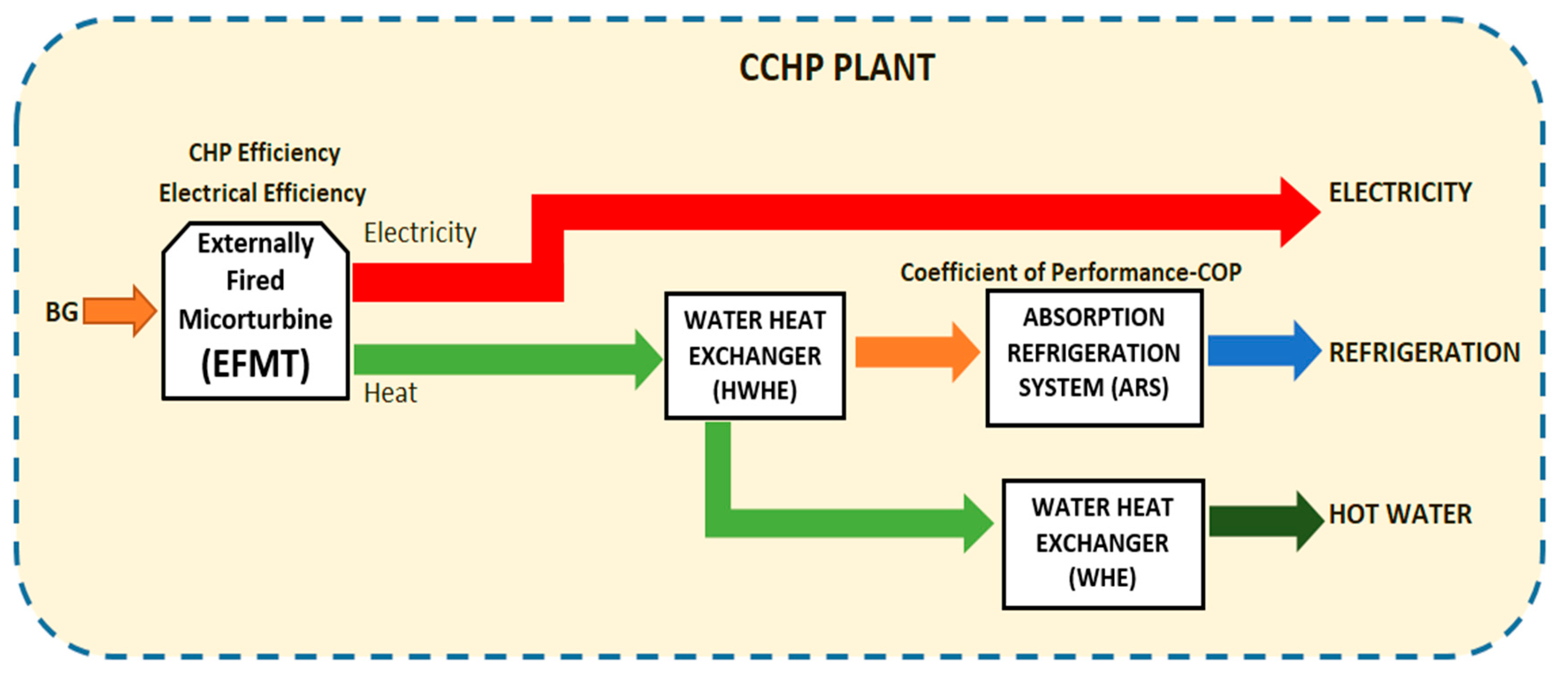
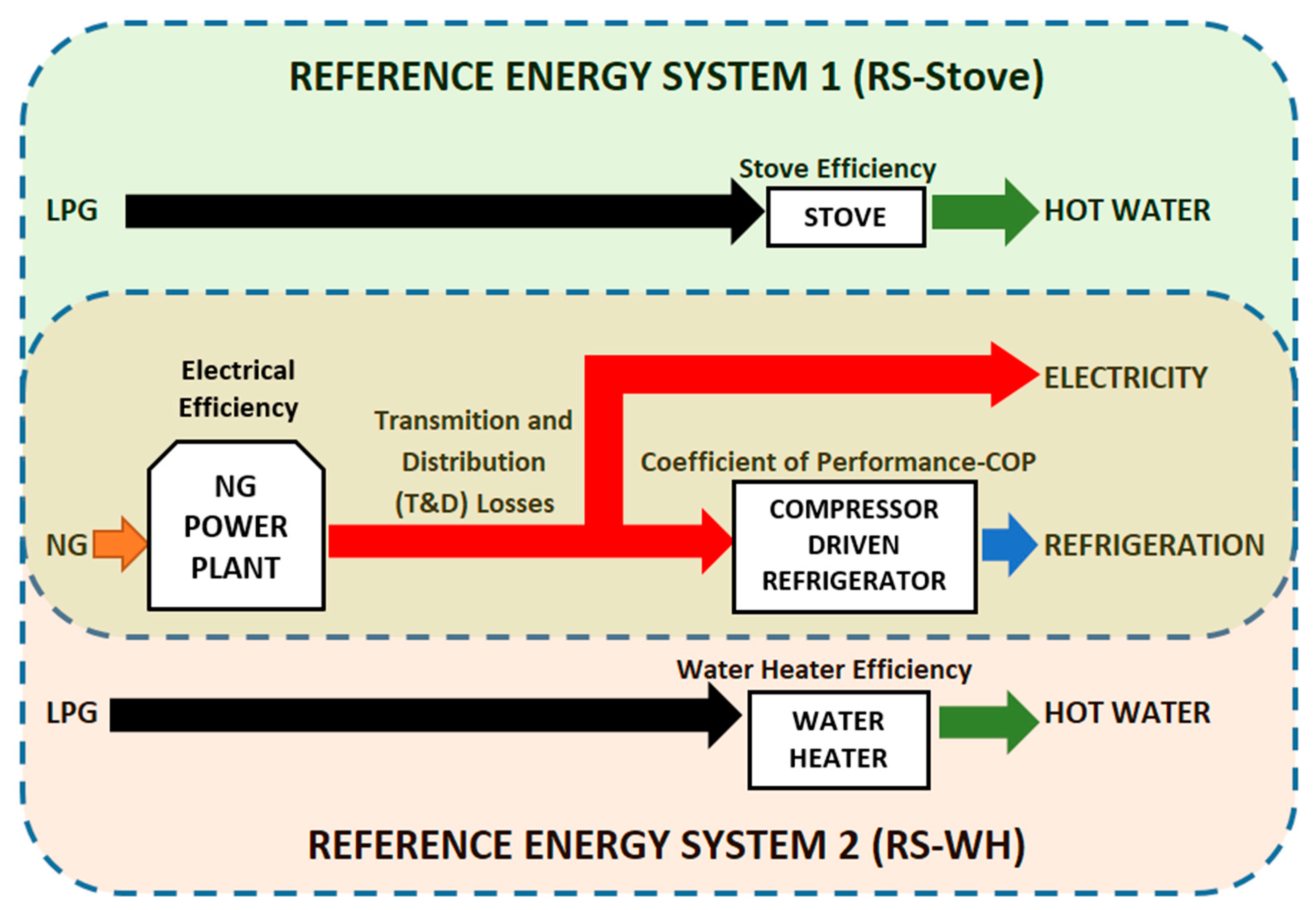
2.1. A Proposed CCHP Plant and the Current Fossil Fuel-Based Solutions (Reference Systems)

The data collected about energy demands of the dairy sector in Bolivia were considered to propose a combined cooling, heat and power (CCHP) solution. This solution considers the use of biogas (BG) for the operation of an externally fired microturbine (EFMT) where electricity and heat (recovered from the combustion gas through heat exchangers) are produced. The heat is used for the production of (i) cooling in the absorption refrigeration system (ARS) and (ii) hot water through a water heat exchanger (WHE). This CCHP solution that supplies electricity, refrigeration and hot water simultaneously is shown in the diagram of Figure 1.
As mentioned previously, energy services in dairy farms (electricity, refrigeration and hot water) are currently supplied by an energy system dependent on fossil fuels. Mainly natural gas power plants (NGPP) supply electricity; this service is used in different appliances and for producing cooling in compressor driven refrigerators. The hot water is supplied by using a water heater (WH) or a common stove (STO), both fueled by liquefied petroleum gas (LPG). The conventional solutions are defined as reference system 1 (RS-Stove), when using the NGPP and a stove, and reference system 2 (RS-WH) when NGPP and a water heater are used. Figure 2 shows these reference systems.
The energy/exergy performances of these energy solutions (proposed CCHP solution and reference systems) are determined for a comparative analysis.

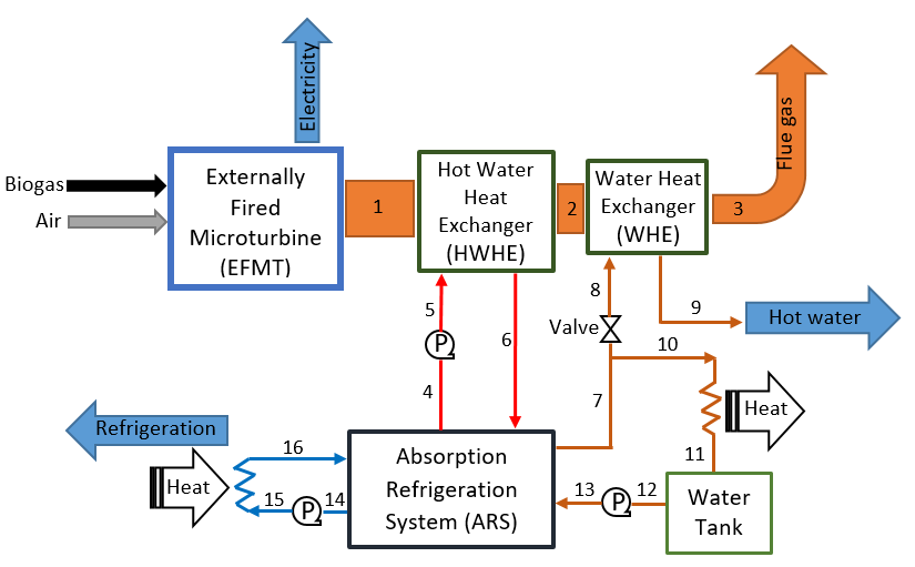
2.2. Description of the CCHP Plant (Absorption Refrigeration System Integrated to the EFMT)

Figure 3 illustrates the processes of the proposed plant. Biogas produced in biodigesters goes to the combustor of the EFMT. The energy from the combustion is used by the EFMT to supply electricity and thermal power that remains available in the flue gas. This thermal power is recovered using a hot water heat exchanger (HWHE) where the flow of water reaches 95 °C. This flow of hot water is the thermal energy source utilized for cooling production in the absorption refrigeration system (ARS). The heat remaining at the flue gas after the HWHE goes to a second water heat exchanger (WHE) to supply water at 55 °C. The final temperature of the flue gas released to the atmosphere has set to be higher than its dew point temperature. Thus, condensate is avoided in the exhaust parts. Beside the biogas (which can also be used in other applications), the final services of this CCHP system are electricity, cooling (for refrigeration) and hot water.
Table 1 presents the circuits and temperatures at the different streams of the CCHP plant.

2.3. Description of the Main Components of the CCHP Plant

• Externally fired microturbine—EFMT
The ET10 microturbine from Compower AB (Sweden) [42] is the main element (prime mover) of the proposed system. The components of the externally fired microturbine are shown in the EFMT diagram shown in Figure 4. They are a compressor (C), a turbine (T), a high temperature heat exchanger (HTHE) and a natural gas combustor with the option to operate biogas (COM). The electric generator (G) is coupled to the same shaft as the compressor and turbine. The thermal cycle starts in the compressor where air from the atmosphere is compressed. The compressed air goes to the (cold) air side of the HTHE where it receives heat from the hot side of the heat exchanger. Compressed hot air leaves the HTHE and enters into the turbine where it is expanded, producing a torque that rotates the shaft. The outlet air stream from the turbine is still warm but the pressure is reduced to close to atmospheric pressure. The outlet air is mixed with the high temperature flue gas from the combustor. This gas is the product of the combustion that takes place at atmospheric pressure. The mixture goes to the (hot) gas side of the HTHE to transfer heat to the compressed air. Finally, the flue gas can go either to a water heat exchanger or to other devices that require heat. The rotational speed of the turbine shaft can vary in the range of 110,000 to 160,000 rpm [56,57]. If the heat transfer capability of the HTHE (considered as a key component) is high, then the turbine inlet temperature (TIT) can be increased (given that the HTHE material can withstand that temperature) and thus the efficiency of the cycle can be improved allowing more electricity production. The HTHE is a crosshead, counterflow heat exchanger with corrugated plates optimized for low pressure drop [7].
According to the design data from Compower AB, the rated outputs of the EFMT prototype should be 5 kWel and 17 kWth. Under test conditions, the company has measured the maximum electric power and found it to be 2 kWel. Analysis of the gap has pointed out the main cause for the difference: The operating speed was limited to 138,000 rpm. While the rated max speed is 160,000 rpm, it was noted that the power requirement of the compressor part increased more than the contribution from the turbine part at speeds above 138,000 rpm. The solution is to do some design modifications in order to improve the performance curve of the turbine and reduce the load curve of the compressor [6]. Such work is in progress. The specification of the ET10 EFMT sets a limit of 650 °C (923.15 K) for the hot side inlet temperature in the HTHE due to material temperature limitations [57]. This temperature corresponds to a turbine inlet temperature (TIT) of 587 °C (860 K) approximately [6]. At the limiting temperature of the HTHE the electrical efficiency is 5.2% and the electrical power is only 1.48 kWel. The data for the microturbine performance under the described conditions is shown in Table 2. This is named the “current state”, while the “nominal state” shows data of the microturbine performance when working at the design conditions, i.e., 5 kWel. For both cases, the CHP efficiency (electricity plus recovered heat divided by the energy inlet rate) is kept the same, but the electrical efficiency is different because of the problems mentioned in the prototype. Table 2 also shows a summary of the inlet and outlet energy flow, fuel energy inlet rate, electricity and heat available for recovering. The rate of energy input is determined with the mass flow of the fuel and its composition (which is related to its low heating value—LHV). The fuel, for both cases, is biogas which is assumed to be a mixture of 35% CO2 and 65% CH4 volume/volume (v/v) [6,58].
• Absorption refrigeration system—ARS
The selected absorption refrigeration system (ARS) is the PC19 Pink Chiller [52]. Figure 5 shows a typical diagram and components of a single effect ARS. The thermally driven refrigeration system selected requires a flow of hot water at around 95 °C (given by the hot water circuit) which goes to the thermal generator (GT) of the absorption cycle where a working fluid (mixture of absorbent and refrigerant) is heated. It causes the evaporation of the fluid with a high level of refrigerant concentration, while inside the generator a weak solution remains that consists mainly of absorbent. The hot evaporated refrigerant goes through a condenser (CON), an expansion valve (EV2) and an evaporator (EVA) in the same way as in a conventional vapor–compressor refrigeration system. It has an absorber (AB), where the expanded refrigerant is mixed with the weak solution causing the absorption of the refrigerant (by the absorbent) in the working fluid. The stream leaving the absorber carries the working fluid to the small pump (P) where the fluid pressure is increased. Then the fluid is preheated in the regenerative heat exchanger (RHE) by the hot “weak solution” stream to be deposited in the generator. Finally, the weak solution leaving the RHE goes through the expansion valve (EV1) to reduce its pressure and be mixed in the absorber for the next cycle [59,60]. The PC19 absorption system also needs a cold water circuit which will supply the cooling and a heat rejection circuit (water at 24 °C or less) for heat dissipation in the condenser (CON), so a cooling circuit that contains a flow of water or other fluid is necessary. The system is able to produce cooling at different temperatures while its COP calculated from the data sheet information is around 0.65 [52].
Data of the ARS Pink Chiller PC19 is shown in Table 3.
The COP of this equipment can have slight variations, with values ranging from 0.65 to 0.68 [61], depending on the temperature conditions of the circuits shown in Table 3. From experimental work (carried out at KTH Royal Institute of Technology) it has been determined that the absorption chiller tries to maintain an optimal value of COP and its performance variation is mostly dependent on the inlet temperatures of the heat-rejection circuit (described in Table 3) [61]. The heat-rejection circuit dissipates the heat using a condenser through a natural convection process. In this study, the circuit temperatures are defined and the COP calculated is 0.65, which is assumed to be constant based in the experimental report [61] (even when the absorption system is working at partial load, i.e., the thermal power given by the hot water circuit is lower than the required by the chiller to work at nominal conditions, which is due to the low flow rate of hot water). The cold water circuit described in Table 3 is used for cooling a milk refrigeration tank (or multiple tanks of lower capacity). As the water outlet temperature in this circuit is below zero, an antifreeze is required. The final temperature in the evaporator of the milk tanks was assumed to be 2 °C considering losses and that the preservation temperature of the product (milk) has to be maximum 4 °C.
The power required for the circulating pumps of the three circuits of the ARS (described in Table 3 and illustrated in Figure 3) is proposed to be supplied by the electricity produced in the CCHP system; these small pumps demand between 85 W and 470 W working at full load (data obtained from their plates).

2.4. Integration of the ARS to the EFM

The integration of the ARS to the EMT must consider the thermal power and temperature of the fluid (in this case water) that will be used as a heat source. This thermal power comes from the combustion gas of the EFMT, which is proposed to be utilized in two stages. The first stage (HWHE) transfers heat to a flow of water whose inlet and outlet temperatures are set at 88 °C and 95 °C, respectively (streams 5 and 6 in Figure 3 and Table 1). The second stage of heat recovery (WHE) transfers heat to a flow of water whose inlet and outlet temperature are set at 24 °C and 55 °C, respectively (streams 8 and 9 in Figure 3 and Table 1). The combustion gas characteristics and the thermal power recovered in each stage are results from the simulation.
The nominal thermal power required for the PC19 absorption cooling system is 26 kWth, which is provided by hot water at 95 °C flowing at 3.2 m3/h, as described in Table 3. This will allow to supply a cooling capacity of 17 kWth. The thermal power for hot water supply demanded in dairy farms, considering a rate of 4 L per minute, was calculated and fixed at 8.9 kWth. However, the thermal power availability of the combustion gas of the EFMT, shown in Table 2 for both CCHP cases (current and nominal states), is not sufficient to meet the thermal requirement for refrigeration and hot water production simultaneously. Then it is assumed that the absorption refrigeration system (ARS) will be working at partial load supplying less cooling than its nominal capacity.
The diagram in Figure 3 shows that the first heat exchanger (HWHE) recovers heat in a flow of water (stream 6); it goes to the ARS driving the operation of the refrigeration cycle. The circuit for heat rejection in the absorption cycle, which has a lower temperature compared to the hot water circuit, is used to dissipate the heat of the condenser. The water leaving the condenser (preheated water, stream 7) is sent to the second heat exchanger (WHE) for hot water production. Alternatively, the water is deposited in a tank for recirculation in the condenser (Figure 3). Finally, the cooling circuit contains the fluid that recirculates between the ARS and the evaporator (cold circuit).

2.5. Simulation of the Proposed CCHP System

In order to analyze the CCHP system’s features, the power output and the particular characteristics of the combustion gas (used for supplying the proposed thermal services), a simulation in the software “Aspen Hysys V8.4” was carried out. This software offers a library with the required components for the EFMT, combustor and heat exchangers. Figure 6 shows a flowsheet of the simulation. The elements used were a compressor, a turbine and a combustor. A gas-fired heater was used as combustor where all the thermal power was kept in the flue gas to be directed to the HTHE (stream 6_mt in Figure 6). Other components in the circuits are a mixer and three heat exchangers (HTHE, HWHE and WHE). The heat exchanger HWHE supplies the thermal power required by the ARS for cooling production and the WHE supplies hot water. For the combustor, the aim is that it be fueled by biogas. Available data from tests done at KTH Royal Institute of Technology [6,56] were used to validate the results of the simulation.
• Simulation: Main assumptions and input and output data
As the EFMT is able to work with raw biogas [6] (which can be produced in dairy farms without upgrading), this is the fuel that feeds the combustor of the microturbine. The assumed composition of the biogas is a mixture of 35% CO2 and 65% CH4 volume/volume (v/v) [6,58]. Traces of other substances are neglected.
The operation of the system is at steady state conditions while thermal losses are considered negligible. In the heat exchangers used in the simulation (HTHE, HWHE and WHE), the heat of the combustion gas is ideally transferred to the other fluid.
The mechanical efficiency of the turbine in the EFMT is 99% and the electrical efficiency of its electrical generator is 93% [6]. These values are required to determine the electric power of the EFMT.
The simulation for the EFMT was performed considering similar parameters as used by Baina et al. [6] in their study about the same microturbine (prototype ET10). The simulation was also validated with data from tests. In the present simulation, two heat exchangers to supply the thermal services are included (HWHE and WHE in Figure 6). The inputs required for the simulation are as follows: Mass flow of the fluids (fuel, air and water), pressure ratio and isentropic efficiency of the turbine and compressor (parameters detailed in the reference study [6]). Other input parameters are: The water flow rate of the WHE, the inlet/outlet temperatures of the water flows in the HWHE and WHE (these parameters were previously defined in Section 2.4) and the turbine inlet temperature (TIT), which is the parameter that can be manipulated to see the variations in the electric power outlet. Finally, the output parameters from the simulation are: The characteristics of the combustion gas (flow rate, temperature and mass heat capacity), the turbine and compressor work (they are used to determine the electric power) and the heat available (in HWHE) for cooling production in the ARS.
The main difference for the simulation of the current and nominal state is the TIT (stream 3_mt in Figure 6), which is set at 587 °C (860 K) and 672 °C (945 K) for the current and nominal state, respectively. The fuel input rate is almost equal for both cases. These data are shown in Table 2.

2.6. Energetic and Exergetic Performance Indicators for the CCHP Solution

• Equations for energetic performance calculation
The primary energy rate ( P E R ) was found as an appropriate criterion for evaluating the energetic performance of a combined cooling, heat and power plant, a CCHP–trigeneration system. The P E R is the ratio of the supplied energy products (electricity- P e l , cooling- Q e v a and heating- Q h w ) to the energy power contained in the primary fuel,   E n i n (Equation (1)). If separate systems are used to provide these energy services, then the sum of the energy rate content in the fuels should be considered. The higher the P E R , the better the system [53,54,55].
P E R C C H P = Q e v a + Q h w + P e l E n i n
Q e v a , is the cooling supplied by the absorption refrigeration system (ARS). Q e v a , Q g e n (the heat required to drive the ARS) and P p (the power of the pump used to recirculate the working fluid shown in Figure 5) are used to determine the C O P in Equation (2).
C O P = Q e v a Q g e n + P p
The power of the pump (P), P p , is not explicitly described in the datasheet of the ARS. Instead, a total power demand is given; this includes the power required by the pump and the control system, which is 450 W. Assuming that P p does not exceed 150 W, then its influence in the C O P calculation is negligible, when Q e v a and Q g e n are 17 kWth and 26 kWth, respectively.
Equation (3) is used to determine the thermal power, Q g e n , available for driving the absorption refrigeration system (ARS); it considers the mass flow ( m ˙ f g ), heat capacity ( c f g ) and the inlet–outlet temperatures ( T g _ i n and T g _ o u t   in the HWHE) of the flue gas. Q g e n is the heat recuperated by the HWHE.
Q g e n = m ˙ f g c f g ( T g _ i n T g _ o u t )
In Equation (4), Q h w is the heat given by the combustion gas to the water flow in the WHE where the inlet–outlet temperatures of the flue gas are T w _ i n and T w _ o u t , respectively.
Q h w = m ˙ f g c f g ( T w _ i n T w _ o u t )
The electricity produced ( P e l ) in the system can be determined by Equation (5). The work of the turbine ( P t u r ) and compressor ( P c o m ) are known results of the simulation, while mechanical ( η m e c ) and electrical generator efficiencies ( η e g ) are given by a previous study on the ET10 EFMT [6]. The electric efficiency of the CCHP system expressed in percentage is calculated by using Equation (6), where m ˙ f and L H V f are the mass flow and the lower heating value of the fuel, respectively.
P e l = ( P t u r η m e c P c o m ) η e g
η e l = P e l 100 m ˙ f L H V f
Equation (7) was used to determine the power input (energy rate) to the system using the mass flow and the L H V f [62] of the fuel. If more than one fuel flow enters into the system, then the total power input will be the sum of their individual energy rates.
E n i n = m ˙ f L H V f
• Equations for exergetic performance calculation
In the same way as for the P E R calculation, the primary exergy rate ( P E R x ) indicator of the combined system is determined by using Equation (8) where the exergy rate entering the system ( E x i n ,   contained in the fuel) and the exergy rate generated in the services supplied (electricity ( E x e l ), cooling ( E x e v a ) and hot water   ( E x h w ) ) are required. This indicator allows to know to what extent the use of the energy source is being utilized effectively [62,63]. The chemical exergies of the fuels are used to determine the exergy rate entering the system. The temperatures when delivering the thermal services (evaporator   ( T e v a ) and WHE ( T w h e )) and a reference temperature ( T 0 ) are also required to determine the overall exergy performance. The reference temperature for the calculations is set at 25 °C (298.15 K [62,63]).
P E R x C C H P = E x e v a + E x h w + E x e l E x i n
The exergy rates generated when supplying the different services, cooling, heating (hot water) and electricity, follow the next equations [60,63]:
E x e v a = Q e v a ( 1 T 0 T e v a )
E x h w = Q h w ( 1 T 0 T w h e )
E x e l = P e l
Exergy generated in thermal services are affected by the temperature where the service is delivered, while electricity exergy rate is the same as its energetic value (Equation (11)). The exergy rate input to the system is determined using Equation (12), where the mass flow ( m ˙ f ), chemical exergy ( e f ; obtained from the tables in [62]), and the molar mass ( M f ) of the fuel are required. If more than one fuel powers the system, then the sum of the individual exergy rates will be the total exergy rate entering the system.
E x i n = m ˙ f e f M f
For the exergy rate calculations, the temperatures assumed were T e v a   = 2 °C (275.15 K, cooling in the evaporator for all the cases), T w h e = 80 °C (353 K, for hot water production in WHE) and 157 °C (430 K, for hot water production when using a stove or a water heater in reference systems) [64].
• Primary energy/exergy rate of the reference (current) energy systems, RS-Stove and RS-WH
The P E R and P E R x of the reference systems (current fossil fuel-based solutions), where the energy services are produced separately, is determined by adapting Equations (1) and (8). The sum of the electricity, cooling and heating (hot water) supplied is divided by the total sum of the energy rates entering the individual systems used to supply such services (these fuels are natural gas and LPG, described in Section 2.1 and Figure 2). It means that the sum of the energy/exergy rate contained in the flow of natural gas (NG) and LPG is the total inflow. The composition of the fuels used in these systems are 100% methane for NG and 60% propane/40% butane (fraction volume/volume) for LPG.
The electric power used to determine the P E R and P E R x of reference systems considers a typical electrical efficiency ( η e l ) of an NGPP which is 33% and transmission–distribution (T&D) electrical losses that reaches 12% in the Bolivian power system [65]. The performance of the compressor driven refrigerator, C O P e l , was set to 2 (representative data from fieldwork). Finally, the efficiency of the system that provides hot water ( η h w ) is 87% for a water heater (from data plate of the equipment-fieldwork) and 54% [66] for a common stove.

2.7. Energy Saving Rate

The energy saving rates that can be obtained when applying the proposed solutions are calculated using Equation (13). This indicator provides the percentage of energy savings, reflecting the degree of primary energy utilization that the CCHP system has in front of the reference solutions which can be interpreted as the decrease in fuel consumption [53,54,55]. The energy saving rates of the CCHP solutions are calculated when comparing to the reference energy systems, where cooling is supplied by using electricity from the grid and hot water is obtained using a water heater or a common stove as described previously.
Δ e S = ( 1 E n i n E n i n _ s ) 100
E n i n is the total energy rate entering the combined CCHP system, and E n i n _ s is the total energy rate entering the systems where energy services are produced separately, which is given by Equation (14).
E n i n _ s = Q e v a C O P e l η e l + Q h w η h w + P e l η e l
The comparative analysis of the energy systems’ performances should be done considering one of these criteria: (i) Keeping the same energy input rate to the systems (to be compared) to observe which system produces a higher rate of electricity, cooling and heating or (ii) keeping the same amount of energy services supplied (by the systems to be compared) and observing which requires less energy input rate to supply them. Therefore, to determine the energy saving rate in Equation (13) both energy rates (for combined and separate energy systems) consider a similar quantity of the final energy services supplied (electricity, cooling and hot water). The same consideration applies when comparing the P E R and P E R x of the combined CCHP system solutions to those of the reference systems presented [55,64,67].

3. Results and Discussion

3.1. Characteristics of EFMT Flue Gas and Heat Recovery Stages

Table 4 contains the main characteristics of the combustion gas that leaves the high temperature heat exchanger (HTHE) of the EFMT along with the heat recovered in each of the stages of heat recovery. The temperatures at the outlet of the HTHE (coming from the EFMT) are the inlet temperatures for the HWHE (first stage) of heat recovery. The simulation gives the outlet temperatures of the flue gas at the first stage since the inlet/outlet temperatures of the water flowing in the heat exchangers were previously defined (Table 1 and Section 2.4). The outlet temperatures of the HWHE are the inlet temperatures of the WHE (second stage); as in the previous heat exchanger, the inlet and outlet water temperatures are known, therefore the temperatures of the exhaust gas leaving the WHE are also given by the simulation. The combustion gas that leaves the second stage of heat recovery is released to the atmosphere. While the energy rate that enters the system in the current state is lower than in the nominal state (as seen in Table 2), it is possible to see that this case recovers slightly more heat than the nominal one. The higher electrical efficiency of the nominal state compared to the current state allows utilizing more heat to produce electricity; consequently, less heat is available in its combustion gas. The combustion gas released to the atmosphere can still be exploited. However, for the purposes of the proposed CCHP plant, which requires a flow of water of 4 L/min at a temperature of 55 °C (in the second stage), the combustion gas has already supplied the heat required.
Table 4 shows that in the first stage the heat recovered from the flue gas of the EFMT does not reach the required 26 kWth thermal heat required for driving the ARS at full load. This means that the ARS works at partial load as described before. The heat recovered in this stage is around 11 kWth, this will allow supplying around 7 kWth of cooling. The additional heat required can be supplied by adding a preheater in the system to reach the nominal heat demanded by the ARS; however, this will make the system more complex and less efficient. The second stage of heat recovery delivers a thermal power of around 9 kWth for water heating, which is fixed for both cases, current and nominal.

3.2. Energetic and Exergetic Performance of the CCHP Plant

Table 5 shows the total energy inlet rate required by the CCHP system in the two states and the electricity and thermal services supplied. It includes parameters for production of electricity (in the EFMT), refrigeration (in the ARS), hot water (in the WHE) and CCHP efficiencies. Table 5 also shows that the thermal power recuperated from the EFMT is almost equally distributed for cooling production in the ARS ( Q g e n ) and for hot water production in the WHE ( Q h w ). In both cases (current and nominal state), the CHP nominal efficiency (Compower design data) was kept the same. This indicates the percentage of useful energy (power and heat) provided by the energy source, in this case biogas. While it seems to have a high efficiency (if compared to thermal power plants where heat is not recovered), that does not indicate whether the heat recovered will be used efficiently in the CCHP plant, for example, when this heat is used to operate thermally driven devices with low performance as in the case of the ARS.
Electricity, cooling and hot water outputs are considered when determining P E R and P E R x of the CCHP plant. While the total energy rates entering the systems (in both states) presented in Table 5 are different (and the services supplied have some quantitative differences), it is possible to make relative comparisons of the CCHP efficiencies. It can be seen that the P E R and P E R x of the current state compared to the nominal state present, in general, much better efficiencies than the current state. The high electric efficiency of the EFMT in the nominal state has a positive effect in both performances ( P E R and P E R x ) but this effect is much higher in the P E R x . This is because the exergy rate generated when supplying electricity (which is higher than in the current state) is the same as its energy value (Equation (11)) and is not affected by any temperature as in the case of thermal services (Equations (9) and (10)). The exergetic efficiency of combined energy systems where thermal services are supplied is normally low; this is because the combustion temperatures of the fuels used in the systems are usually higher (and could be better used) compared to the final temperatures of the thermal services supplied [64]. The difference of temperatures is reflected in the exergetic efficiencies.

3.3. Influence of EFMT Electric Efficiency and COP on the CCHP Performance

The key element that influence on the EFMT electric efficiency is the high temperature heat exchanger (HTHE). An improvement on its effectiveness would allow increasing the turbine inlet temperature (TIT) and thus increasing the power supply. In that case, the thermal power available for recuperation in the combustion gas would be reduced. The effectiveness of the HTHE can be enhanced by using materials that improve the heat transfer, reduce pressure drops and/or increase the heat transfer area [7,39,68]. Additionally, a proper design and matching of the compressor and turbine in the EFMT would help to improve the electric efficiency. Since the ET10 Microturbine is a prototype, it will undergo further studies and improvements that can enhance its performance.
Absorption refrigeration systems (ARS), as in the case of the PC19 chiller, generally have a low C O P when compared to the performance of conventional compressor driven refrigeration systems. However, studies are being carried out to look for performance improvement in the absorption cycle [69]. Literature shows that this can be achieved with the application of different working fluids and/or improvements in the design features of the circuit, which implies the incorporation of more efficient and/or new elements [70,71].
In order to analyze the effect on the availability of the supplied services and on the CCHP performance, it is proposed to increase reasonably the electrical efficiency of the EFMT and the C O P of the ARS based on existing literature. This is done for the nominal state presented previously. The electrical efficiency of the EFMT is increased from 15.7% (nominal state) up to 20%, which is an achievable target when considering the use of ceramic materials in the HTHE, for example [7,39]. The C O P is increased from 0.65 (Pink Chiller C O P ) up to 0.75, which is in the range of existing absorption cooling systems [9,70]. Table 6 shows the nominal state, the nominal state with the increase of the electric efficiency (NS-EE), the nominal state with the increase of the C O P (NS-COP) and the nominal state where both parameters are increased simultaneously (NS-EE&COP).
The comparison of the CCHP system variants considers the nominal state as a reference. The same energy input rate (same mass flow of biogas) enters to the CCHP systems, as can be seen in Table 6. As expected, the enhancement of any of the parameters previously discussed has a positive influence on the overall performance of the system and also on the availability of the supplied services. However, the improvement of only one parameter would lead to a different effect on the system performance. The higher effect on the P E R x (than on the P E R ) caused by increasing only the electric efficiency (NS-EE) is because electricity has a greater exergetic value (being the same value as its energetic value), which is different for thermal services. In this case, the improved electric efficiency allows producing more electricity but less cooling because of less heat being available in the combustion gas. The higher effect on the P E R (than on the P E R x ) caused by increasing only the C O P (NS-COP) is due to the better performance of the ARS which requires the same amount of heat to supply more cooling. In this case, the production of electricity remains the same as in the nominal state. If both parameters are increased simultaneously (NS-EE-COP) more electricity and cooling than in the nominal state are supplied while keeping the same rate of energy entering the systems. Then the energetic/exergetic performances of the CCHP system increase considerably. In general, when comparing energy solutions, a high P E R indicates that less fuel (in terms of energy) is required to supply the same rate of energy services (or a higher rate of energy services can be supplied keeping the same fuel demand). A high P E R x means that the energetic potential of the fuel (biogas for the CCHP solution in this study) is being favorably exploited.
In the present study, the overall performance of the CCHP solutions ( P E R ) was found in a range of 0.64 to 0.71 (Section 3.2 and Section 3.3). Mehr et al. [17] have found an average overall efficiency for a fuel cell-based trigeneration system of around 0.72. Two cases of solar driven CCHP systems (Rankine cycle) were presented by Eisavi et al. [16]. The overall efficiency of the systems was found at 1.0 and 0.90 (these values were calculated with data presented in that study) for a C O P of the absorption refrigeration system of 1.18 and 0.79, respectively. Ghaebi et al. [14] found an overall efficiency of 0.84 for another CCHP (gas turbine-heat recovery steam generator) solution. However, these results correspond to systems of particular characteristics (higher energy demands, different prime movers and different efficiency of the CCHP components). In this scenario, comparisons of the performance results with those of other CCHP solutions have to be done with special care because of the fact that each CCHP (trigeneration) system is specifically designed for a particular application where some variables have important influence on its overall performance. These variables are: Configuration of the system (arrangement of the components), electric efficiency of the power generator, thermal recovery capacity, share of use of recovered heat (used for heating/cooling), efficiency of the absorption refrigeration system ( C O P ), and thermal demand characteristics (rate and temperatures). These parameters normally vary for each application. Therefore, comparisons between these alternative solutions should be carried out as suggested in Section 2.7.

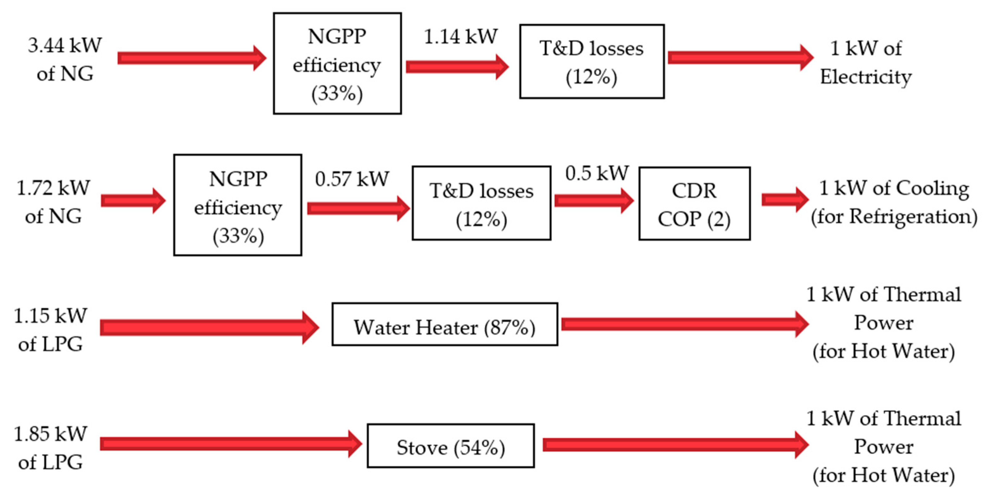
3.4. Performance Comparison of the Reference Energy Systems Versus the CCHP Solutions

Figure 7 and Figure 8 show the energetic and exergetic performance ( P E R and P E R x ) of the reference energy systems (fossil fuel-based solutions where energy services are produced separately) versus the proposed CCHP system (current and nominal states). These comparisons are carried out considering the primary fuel energy and exergy rates entering the reference systems, i.e., natural gas for electricity production (used for refrigeration and appliances) in thermal power plants (NGPP), liquefied petroleum gas for hot water supply either using a stove (STO) or a water heater (WH). Then the reference systems are: RS-Stove, when using NGPP and STO; and RS-WH, when using NGPP and WH. Finally, biogas is the fuel for the CCHP solutions in the current and nominal states.
The comparison between the performances of reference systems and CCHP solutions is carried out when similar quantities of electricity, cooling and hot water are supplied. Table 5 has shown that the production of electricity in the CCHP-current state is lower than in the CCHP-nominal state, therefore the reference systems must consider the same amount of electricity (and the rest of the supplied thermal services) to be compared to the CCHP solutions. This is reflected in the variation of the reference system (RS-Stove and RS-WH) performances shown in Figure 7 and Figure 8 where these systems are compared to the CCHP solution in its current and nominal state, respectively.
In Figure 7 the comparison is done considering the current state of the EFMT microturbine (data from tests done on the microturbine), which is arranged in the CCHP system. Interestingly, the ARS integrated to the microturbine in a CCHP plant (CCHP-current state) has the best energetic performance, P E R , (despite its low electrical efficiency) compared to both reference systems. This shows that even under the current state of the microturbine, this solution can be considered a good option. This is mainly due to the utilization of waste heat to supply the demanded thermal services. However, the exergetic performance, P E R x , is lower compared to both reference systems, the main reason is the low electric efficiency of the EFMT. In general, combined systems that recover heat to provide thermal services (to a greater extent than electricity as in this case) will have lower exergetic performance ( P E R x ) than those that are exclusively destined for electricity generation.
Figure 8 shows the comparison of the reference systems versus the CCHP system in the nominal state (with design data provided by Compower) of the EFMT microturbine. It is clear that the externally fired microturbine as the prime mover of the CCHP system allows having much higher energetic performances compared to both reference systems. This is due to the higher electric efficiency, which leads to supplying more electricity and less heat in the combustion gas. This has a positive effect on both performances—energetic and exergetic, P E R and P E R x , respectively. The increase of the exergetic performance, P E R x , of the CCHP solution shows that the energy potential of biogas is better exploited than the fossil fuels used in the reference systems. The application of a CCHP system, under the nominal conditions, is definitely the most adequate solution in front of the reference solutions since it has higher energetic and exergetic performances.
The integration of the prototype EFMT-ET10 and the ARS-PC19 under the current technical conditions has already shown better energetic performance than the reference systems. However, it is seen that achieving the nominal value of the electric efficiency of the EFMT (nominal state) will allow having much better performances, as shown in Figure 8.

3.5. Energy Saving Rates as a Result of Using the Proposed CCHP Solutions

Figure 9 shows the energy saving rates that could be achieved if the proposed solutions were implemented; this compared to the two reference systems. As mentioned in Section 2.1, the reference energy system has only one variant. The power grid coming from natural gas power plants supplies electricity for diverse uses and for refrigeration, while hot water is supplied by using a common stove (RS-Stove) or using a water heater (RS-WH), both fueled with LPG.
Figure 9 also shows a table where data should be interpreted as follows: The CCHP system in the current state will allow an energy saving rate of 18.65% compared to the reference system, RS-Stove, and 0.74% if compared to the reference system, RS-WH. The current state (EFMT with low electrical efficiency) compared to the RS-WH shows almost negligible savings. However, compared to the RS-Stove this solution has important energy rate savings. The nominal state shows higher energy rate savings compared to both reference solutions. The last three CCHP solutions are the hypothetical cases presented in Section 3.3 where improvements in the electric efficiency of the EFMT and COP of the ARS are assumed (Table 6). These solutions show much higher energy saving rates compared to the reference energy systems and to the rest of the solutions. In summary, using the CCHP system in the current state will allow energy saving rates up to 18.65%, the nominal state savings greater than 30%, while the cases of improved performances can lead to savings of up to about 37%. All the input/output parameters and results of the calculations for the performances and energy rate savings of the CCHP system (in its different variations) are presented in detail in Appendix B.
In general, it has been found that the proposed methodology for analyzing the performance of this type of CCHP system was satisfactorily applied by making the necessary considerations. In this way, it has been possible to fill the research gap identified in the introductory section.
The results presented in this section show that the EFMT as the prime mover of a CCHP plant, in its different states, has better energy performance than the fossil fuel-based reference solutions (it includes the CCHP system with the EFMT under the current state, i.e., with low electric efficiency). Likewise, the higher exergetic performance shows a favorable exploitation of the fuel. Consequently, the proposed CCHP solution in all the variations generates energy rate savings when compared to the reference systems. The implications of these results can be approached from different perspectives:
  • Development of technology; it can be concluded that, to achieve high performances in the CCHP system in real conditions, further efforts will be required in the research. This will allow developing efficient equipment that can be integrated in a CCHP solution generating energy savings as high as the values found for the nominal and hypothetical cases in this work. Considering this, the performance analysis of the EFMT, as the main component of the proposed CCHP solution, allows identifying potential improvements required in certain elements of the equipment, for example, in the high temperature heat exchanger which is the key element of the EFMT.
  • Energy access in rural areas; because of the features of the EFMT, the proposed CCHP system considers the use of raw biogas that can be produced in rural areas without requiring sophisticated equipment. Therefore, rural users (farmers/small agro-industries) can meet their energy demands while exploiting the energy potential of local available organic waste. This is addressed in this study where it is proposed to meet the electricity and thermal demands of small dairy farms in rural areas.
  • Displacement of fossil fuel use; the application of the proposed biogas-based energy solution would allow displacing/avoiding the use of fossil fuels and the associated negative effects to the environment caused by their use. Therefore, the proposed system can be considered as a suitable energy solution for rural areas with biogas production potential and diverse energy demands.
While the results of this study are properly justified, these findings have to be seen in light of some limitations. One of the limitations is the comparison of the CCHP system performance with those of fossil fuel-based reference systems. The performance of the reference systems can change over the time. This means that improvements in the efficiencies and/or reduction of energy losses (power grid) of the conventional technologies can make the reference systems more efficient than the proposed solution. In this case, the results are sensitive to the variation of the reference systems’ performance; however, the proposed methodology is totally valid and applicable for analyzing the performance of this type of trigeneration systems. A second limitation is the steady state conditions that were assumed for the proposed CCHP solutions. The various energy services are supplied simultaneously without considering variations and demand cycles. This can be addressed in future research in order to define proper operation strategies of the system when the demand is not constant.

3.6. Further Considerations: Future Work and Feasibility for the Implementation of the CCHP Solution

Based on the results obtained and with a broader view regarding the implications of the results, some actions that should be carried out by the involved parties are suggested. On the part of the researchers, the development of the technologies proposed in this study would be achieved with continuous investigations. This research should include exploration of potential applications not only in isolated rural areas but also in places where this solution can be suitable. On the part of the manufacturers, the improvements of these technologies, as a result of the research, would allow manufacturers to develop commercial equipment that should be easily implemented at the application sites. This development must inevitably be done with the necessary techno-economic considerations. On the part of the government/policymakers, once the technologies for this type of system are available in the market, the implementation of these combined energy solutions in rural areas can be promoted through policies that consider financial and technical support. This would help to improve access to energy services in rural areas. Another aspect that should be considered as a public policy is the dissemination of information about alternative energy solutions in rural areas. This will help rural people to be better prepared to deal with issues raised when implementing and operating alternative energy solutions like the CCHP system presented in this study.
The feasibility of implementation of the biogas-based CCHP solution presented in this study can be addressed considering technical and economic aspects that involve the three main components of the system that are proposed for the production of biogas, electricity/heat, and refrigeration.
  • As stated in the introductory section, a detailed study of biogas production is not part of this research; however, the use of low-cost tubular biodigesters, which are suitable for implementation in rural areas without major technical and economic inconveniences, is suggested.
  • The microturbine (EFMT) that supplies electricity and heat is a prototype, the technology of which is still in development; in this case, long-term operation intervals are not guaranteed. However, this study shows that this microturbine integrated in a CCHP system offers advantages over other conventional technologies. In this scenario, future advances in the improvement of this technology will probably allow this equipment to be available in the market.
  • The absorption refrigeration system (ARS) proposed in the CCHP system is commercially available; however, as previously mentioned, the cooling capacity is higher than that required in the proposed system. In this case, a refrigeration system with lower cooling capacity would be appropriate for the proposed CCHP system. This would probably involve lower cost of the refrigeration equipment. However, absorption refrigeration systems with low cooling capacity are still difficult to find in the market.
Considering this complex scenario, where some technical aspects still need to be solved, a feasibility study, from an economic point of view, must be carried out carefully. This study should take into account each of these particular aspects and the specific market conditions of the place of implementation. This is a necessary next step and will be better approached in particular research, since the focus of the present study is related to analyzing the energy performance of the proposed CCHP system. Finally, the analysis conducted in this study for this particular energy system (biogas-based CCHP system for small-scale applications) satisfies the gap in research that has been identified. In addition, the methodology proposed to evaluate the performance of a CCHP (trigeneration) system is applicable for performance analysis of similar energy solutions.

4. Conclusions

An integration of a commercially available absorption refrigeration system (Pink PC19) with an externally fired microturbine prototype (Compower ET10) and two water heat exchangers was presented. It was proposed that this trigeneration (CCHP) system be fueled by raw biogas produced in small dairy farms. The final services are electricity, cooling (for milk refrigeration) and hot water (for cleaning purposes in farms). Data about the size of refrigeration systems required in Bolivian dairy farms were collected to have a reference of the small-scale cooling demands. The study focuses on evaluating the overall performance of a CCHP system (with variations on the components’ efficiencies) using the primary energy/exergy rate indicator. Then these performances are compared to those of reference energy systems (fossil fuel-based solutions) considering energy saving rates that can be achieved if the proposed solutions were used. The main conclusions can be summarized as follows:
  • This combined system is mainly dedicated to the fulfilment of low cooling demands (around 7 kWth) required for milk preservation in small dairy farms.
  • As expected, the CCHP system that considers the nominal state (high electric efficiency) of the microturbine has shown better energetic ( P E R ) and exergetic ( P E R x ) performances than the system that considers the microturbine in the current state (low electric efficiency).
  • The current state case has shown still higher energy performance than the fossil fuel-based reference systems where energy services are produced separately. However, the exergy performance in this case is lower than those of the reference systems. The energy rate savings generated for this case when compared to the reference systems was found to be up to 19%.
  • The nominal state case showed the higher energy and exergy performances in front of the performances of the reference systems. That is mainly due to the higher electricity production. In this case the energy rate savings generated were found to be higher than 30%.
  • The nominal state case was evaluated when considering improvements in the electric efficiency of the ET10 (from 15.7 to 20%) and in the C O P (from 0.65 to 0.75) for the absorption refrigeration system PC19. The enhancement of these parameters allows improving the overall efficiency of the system and shows energy rate savings higher than 37%.
  • The technology of the small-scale externally fired microturbine integrated as the prime mover of a trigeneration (CCHP) system is an attractive alternative compared to conventional energy solutions, because of its capability to work with different fuels that do not require high quality in terms of purity. Consequently, it can be applied not only in remote rural areas but also in already electrified areas where fuels derived from biomass as biogas can be exploited to supply diverse energy demands. However, further studies are required to enhance the efficiency of the components of the CCHP system in an economic approach.
  • For the particular case of dairy farms located in central Bolivia, the production and use of biogas to supply various energy services helped to reduce dependence on the power grid. Substitution of natural gas and liquefied petroleum gas by biogas can also contribute to reduce greenhouse gas emissions while exploiting alternative energy resources such as the waste generated in farms.

Author Contributions

All authors contributed to the paper as follows. Conceptualization, J.V.-S. and A.M. (Anders Malmquist); Methodology, J.V.-S., J.A.A. and J.M.-H.; Software, J.V.-S.; Validation, J.V.-S. and J.A.A.; Formal Analysis, J.V.-S., J.A.A., A.M. (Anders Malmquist), J.M.-H. and A.M. (Andrew Martin); Investigation, J.V.-S.; Resources, J.V.-S., A.M. (Anders Malmquist) and A.M. (Andrew Martin); Data Curation, J.V.-S.; Writing—Original Draft Preparation, J.V.-S. and J.M.-H.; Writing—Review and Editing, J.V.-S., A.M. (Anders Malmquist), J.M.-H. and A.M. (Andrew Martin); Visualization, J.V.-S. and J.M.-H.; Supervision, A.M. (Anders Malmquist) and A.M. (Andrew Martin).

Funding

This research received no external funding.

Acknowledgments

This study was carried out as a part of SIDA’s research cooperation with Universidad Mayor de San Simon (UMSS). The strategic research project STandUP for Energy contributed to supervision of the work. Dr. Lucio Alejo collaborated with administrative tasks at UMSS. The dairy farmers association (Asociación de Productores de Leche—APL) and farmers from Alba Rancho in central Bolivia (Cochabamba) contributed with valuable data collected during fieldwork and interviews.

Conflicts of Interest

The authors declare no conflict of interest.

Nomenclature

cSpecific mass heat capacity (kJ/kg K)
eStandard molar chemical exergy (KJ/kmol)
EnEnergy flow rate (kW)
ExExergy flow, rate (kW)
MMolar mass (kg/mol)
m ˙ Mass flow rate (kg/s)
ηEfficiency (%)
PPower (kWel)
QHeat flow rate (kWth)
TTemperature (°C/K)
ΔSaving (%)
Note: kWel is used for electric power, kWth is used for thermal power and kW is used for either mechanical power or for the power contained in a fuel.

Subscripts

0Reference state
comCompressor
elElectricity
egElectrical generator
eSEnergy saving
evaEvaporator
fFuel
fgFlue gas
genARS Generator
g_inInlet to the HWHE
g_outOutlet from the HWHE
hwHot water
inInlet
in_sInlet to separate systems
mecMechanical
pPump
thThermal
turTurbine
wheWater heat exchanger
w_inInlet to the WHE
w_outOutlet from the WHE

Abbreviations

ARSAbsorption Refrigeration System
BGBiogas
CCHPCombined Cooling, Heat and Power
CDRCompressor Driven Refrigerator
CHPCombined Heat and Power
COPCoefficient of Performance (dimensionless)
EEElectric Efficiency
EFMTExternally Fired Microturbine
HTHEHigh Temperature Heat Exchanger
HWHEHot Water Heat Exchanger
LHVLow Heating Value (kJ/kg)
LPGLiquefied Petroleum Gas
NSNominal State of the EFMT
NGNatural Gas
NGPPNatural gas power plant
PERPrimary Energy Rate (dimensionless)
PERxPrimary Exergy Rate (dimensionless)
RSReference system
STOStove
TITTurbine Inlet Temperature
WHWater Heater
WHEWater Heat Exchanger

Appendix A

Fieldwork in Bolivian small dairy farms;
The fieldwork was carried out in small dairy farms located in central Bolivia, Cochabamba, specifically in the community of Alba Rancho. This work was done during September 2016. Staff of the Association of Milk Producers (APL) collaborated with the work. The objective was to collect information regarding the energy demands of this sector.
It was found that the main energy demands of the dairy farms were electricity for milking machines, pumps and other appliances; refrigeration for the preservation of milk in optimal conditions; and hot water for sanitation and cleaning of milking equipment and tanks.
At the time of the fieldwork, the farms had electricity service from the grid, which was used to cover the electricity and refrigeration demand (with the use of conventional refrigerators). These refrigerators were found in poor conditions, most of them old and without adequate maintenance (which greatly affects their performance). To get hot water, only one of the farms had a water heater while the rest used conventional stoves; they were both fueled by LPG.
Types of farms: Small farms managed by families predominate in the area (with around 10 to 60 dairy cows). Many of them share a common milk storage center since their milk production is less than 200 L per day. Some dairy farmers with higher milk production have their own refrigeration system. Four farms (three of them with their own refrigeration systems and one being a storage center) were visited during the fieldwork; the information collected is shown in Table A1.
Table A1. Thermal energy demands collected from fieldwork in Bolivian dairy farms.
Farm 1Farm 2Farm 3Farm 4 1
Milk ProductionLt/day5206106551220
Cooling Capacity 2kWth6.057.097.6114.18
COP-22.524
Temperature for Milk Preservation°C4444
Energy Source for Refrigerator-GridGridGridGrid
Hot Water supplyLt/min4468
Temperature of Hot Water 3°C55555555
Equipment for Hot Water Supply-StoveStoveWHStove
Efficiency 4%54548754
Energy Source for Hot Water-LPGLPGLPGLPG
1 Corresponds to a milk storage center. 2 It was determined considering the milk production and temperatures for milk preservation. 3 Recommended temperature of hot water [51]. 4 Water heater efficiency from data plate of the equipment; stove efficiency from [66].
These data were considered as a reference for the proposed CCHP system in this study. The COP for the reference system was set at 2, and the hot water demand was fixed at 4 L per minute. This reference is also useful for other small-scale applications where trigeneration systems can be applied.
Reference (fossil fuel-based) energy systems:
Bolivia’s power system is predominantly dependent on thermo-electric power plants, which mainly use natural gas. From technical reports of the institution that controls the electric market, it was estimated that the efficiency of these natural gas-based power plants (NGPP) is around 33%. On the other hand, transmission and distribution losses (T&D) are estimated to be around 12% [65].
Figure A1 illustrates the primary energy rate required to supply the energy services considering the power system performance and the equipment efficiencies; this is for the case of Bolivia. However, this reference is valid by the time in which the data was taken (year 2016) since the efficiencies of the power system, energy losses and performance of the equipment may suffer variations.
Figure A1. Primary energy rate required for supplying energy services.
Energies 12 03830 g0a1

Appendix B

Table A2. Complete input data used for calculations of performances and energy savings for all the CCHP cases—results of performances and energy saving rates.
ParameterUnitCCHP Current StateRS-StoveRS-WHCCHP Nominal StateRS-StoveRS-WHCCHP NS-EERS-StoveRS-WHCCHP NS-COPRS-StoveRS-WHCCHP NS-EE&COPRS-StoveRS-WH
ElectricitykW1.481.481.485.005.005.006.396.396.395.005.005.006.396.396.39
Power Plant Type-EFMTNGPPNGPPEFMTNGPPNGPPEFMTNGPPNGPPEFMTNGPPNGPPEFMTNGPPNGPP
Efficiency for Electricity Production%5.2%33%33%15.7%33%33%20.0%33%33%15.7%33%33%20.0%33%33%
T&D Losses %-12%12%-12%12%-12%12%-12%12%-12%12%
Fuel for Electricity Production-BiogasNG NG BiogasNG NG BiogasNG NG BiogasNG NG BiogasNG NG
Mass Flow of Fuelkg/s0.001400.000100.000100.001580.000340.000340.001580.000440.000440.001580.000340.000340.001580.000440.00044
LHVkJ/kg202005002050020202005002050020202005002050020202005002050020202005002050020
Energy Inlet Rate of Fuel for Electricity ProductionkW28.245.105.1031.9317.2217.2231.9321.9921.9931.9317.2217.2231.9321.9921.99
Thermal power for Hot WaterkW8.928.928.928.928.928.928.928.928.928.928.928.928.928.928.92
Equipment for Hot Water Production-WHEStoveStoveWHEStoveStoveWHEStoveStoveWHEStoveStoveWHEStoveStove
Efficiency for Hot Water Production%100%54%87%100%54%87%100%54%87%100%54%87%100%54%87%
Fuel for Hot Water Production--LPGLPG-LPGLPG-LPGLPG-LPGLPG-LPGLPG
Mass Flow of Fuelkg/s-0.0003590.000223-0.0003590.000223-0.0003590.000223-0.0003590.000223-0.0003590.000223
LHVkJ/kg-46062.8246062.82-46062.8246062.82-46062.8246062.82-46062.8246062.82-46062.8246062.82
Energy Inlet Rate of Fuel for Hot Water ProductionkW-16.5210.25-16.5210.25-16.5210.25-16.5210.25-16.5210.25
Heat required for Hot Water ProductionkW8.92--8.92--8.92--8.92--8.92--
Cooling (Refrigeration)kW7.617.617.617.207.207.206.306.306.308.318.318.317.277.277.27
Equipment for Cooling Production-ARSCDRCDRARSCDRCDRARSCDRCDRARSCDRCDRARSCDRCDR
Performance for Cooling Production-0.65220.65220.65220.75220.7522
Electricity required for Cooling ProductionkW-3.813.81-3.603.60-3.153.15-4.154.15-3.633.63
Efficiency for Electricity Production%-33%33%-33%33%-33%33%-33%33%-33%33%
T&D Losses%-12%12%-12%12%-12%12%-12%12%-12%12%
Fuel for Electricity Production (for cooling)--NG NG -NG NG -NG NG -NG NG -NG NG
Mass Flow of Fuelkg/s-0.0002620.000262-0.0002480.000248-0.0002170.000217-0.0002860.000286-0.0002500.000250
LHVkJ/kg-5002050020-5002050020-5002050020-5002050020-5002050020
Energy Inlet Rate of Fuel for Cooling ProductionkW-13.1013.10-12.4012.40-10.8410.84-14.3014.30-12.5112.51
Thermal Power required for Cooling ProductionkW11.71--11.08--9.69--11.08--9.69--
Total Energy Inlet Rate (fuel)kW28.2434.7228.4531.9346.1339.8731.9349.3543.0931.9348.0441.7731.9351.0244.76
Total Energy Outlet Rate (services)kW18.0118.0118.0121.1221.1221.1221.6021.6021.6022.2322.2322.2322.5722.5722.57
Reference Temperature K298.15298.15298.15298.15298.15298.15298.15298.15298.15298.15298.15298.15298.15298.15298.15
Exergy Rate for supplying ElectricitykW1.481.481.485.005.005.006.396.396.395.005.005.006.396.396.39
Exergy Rate for production of ElectricitykW29.645.285.2833.5117.8517.8533.5122.7922.7933.5117.8517.8533.5122.7922.79
Chemical exergy/Molar mass (inlet fuel)kJ/kg21200.551848.551848.521200.551848.551848.521200.551848.551848.521200.551848.551848.521200.551848.551848.50
Exergy rate for supplying Hot WaterkW1.392.742.741.392.742.741.392.742.741.392.742.741.392.742.74
Exergy rate for production of Hot WaterkW-17.4210.81-17.4210.81-17.4210.81-17.4210.81-17.4210.81
Average Temperature for supplying Hot WaterK 353.15430430353.15430430353.15430430353.15430430353.15430430
Chemical exergy/Molar mass (inlet fuel)kJ/kg-48571.948571.9-48571.948571.9-48571.948571.9-48571.948571.9-48571.948571.9
Exergy rate for supplying CoolingkW0.640.640.640.600.600.600.530.530.530.690.690.690.610.610.61
Exergy rate for production of CoolingkW-13.5813.58-12.8512.85-11.2411.24-14.8314.83-12.9712.97
Average Temperature for supplying CoolingK 275.15275.15275.15275.15275.15275.15275.15275.15275.15275.15275.15275.15275.15275.15275.15
Chemical exergy/Molar mass (inlet fuel)kJ/kg-51848.551848.5-51848.551848.5-51848.551848.5-51848.551848.5-51848.551848.5
Total Exergy Inlet Rate (fuel)kW29.6436.2829.6833.5148.1241.5133.5151.4544.8433.5150.0943.4833.5153.1846.58
Total Exergy Outlet Rate (services)kW3.514.854.856.998.348.348.309.659.657.088.438.438.389.739.73
PER-0.6380.5190.6330.6610.4580.5300.6770.4380.5010.6960.4630.5320.7070.4420.504
PERx 0.1180.1340.1630.2090.1730.2010.2480.1880.2150.2110.1680.1940.2500.1830.209
Energy Saving Rates%-18.65%0.74%-30.78%19.90%-35.30%25.89%-33.53%23.56%-37.42%28.66%

References

  1. International Institute of Refrigeration (IIR). The Role of Refrigeration in the Global Economy; Infromatory Note on Refrigeration Technologies; IIR: Paris, France, 2015. [Google Scholar]
  2. UNEP Ozone Secretariat. Fact Sheet 5—Industrial Refrigeration; Workshop on HFC Managament; Technical Issues; Bangkok, Thailand, 2015; Available online: http://www.gluckmanconsulting.com/wp-content/uploads/2015/04/FS-5-Industrial-Refrigeration-final.pdf (accessed on 18 November 2018).
  3. Kalogirou, S.; Florides, G.; Tassou, S.; Wrobel, L. Design and Construction of a Lithium Bromide Water Absorption Refrigerator. In Proceedings of the CLIMA 2000/Napoli 2001 World Congress, Napoli, Italy, 15–18 September 2001; pp. 15–18. [Google Scholar]
  4. Elz, D. Bioenergy systems. Q. J. Int. Agric. 2007, 46, 325–332. [Google Scholar]
  5. Wegener, M.; Malmquist, A.; Isalgué, A.; Martin, A. Biomass- fi red combined cooling, heating and power for small scale applications—A review. Renew. Sustain. Energy Rev. 2018, 96, 392–410. [Google Scholar] [CrossRef]
  6. Baina, F.; Malmquist, A.; Alejo, L.; Fransson, T.H. Effect of the fuel type on the performance of an externally fired micro gas turbine cycle. Appl. Therm. Eng. 2015, 87, 150–160. [Google Scholar] [CrossRef] [Green Version]
  7. Baina, F.; Malmquist, A.; Alejo, L.; Palm, B.; Fransson, T.H. Analysis of a high-temperature heat exchanger for an externally-fired micro gas turbine. Appl. Therm. Eng. 2015, 75, 410–420. [Google Scholar] [CrossRef] [Green Version]
  8. Al-Sulaiman, F.A.; Hamdullahpur, F.; Dincer, I. Trigeneration: A comprehensive review based on prime movers. Int. J. Energy Res. 2011, 35, 233–258. [Google Scholar] [CrossRef]
  9. Jradi, M.; Riffat, S. Tri-generation systems: Energy policies, prime movers, cooling technologies, configurations and operation strategies. Renew. Sustain. Energy Rev. 2014, 32, 396–415. [Google Scholar] [CrossRef]
  10. Murugan, S.; Horák, B. Tri and polygeneration systems—A review. Renew. Sustain. Energy Rev. 2016, 60, 1032–1051. [Google Scholar] [CrossRef]
  11. Jana, K.; Ray, A.; Majoumerd, M.M.; Assadi, M.; De, S. Polygeneration as a future sustainable energy solution—A comprehensive review. Appl. Energy 2017, 202, 88–111. [Google Scholar] [CrossRef]
  12. Ebrahimi, M.; Keshavarz, A.; Jamali, A. Energy and exergy analyses of a micro-steam CCHP cycle for a residential building. Energy Build. 2012, 45, 202–210. [Google Scholar] [CrossRef]
  13. Wang, J.J.; Yang, K.; Xu, Z.L.; Fu, C. Energy and exergy analyses of an integrated CCHP system with biomass air gasification. Appl. Energy 2015, 142, 317–327. [Google Scholar] [CrossRef]
  14. Ghaebi, H.; Amidpour, M.; Karimkashi, S.; Rezayan, O. Energy, exergy and thermoeconomic analysis of a combined cooling, heating and power (CCHP) system with gas turbine prime mover. Int. J. Energy Res. 2011, 35, 697–709. [Google Scholar] [CrossRef]
  15. Badami, M.; Portoraro, A.; Ruscica, G. Analysis of trigeneration plants: Engine with liquid desiccant cooling and micro gas turbine with absorption chiller. Int. J. Energy Res. 2012, 36, 579–589. [Google Scholar] [CrossRef]
  16. Eisavi, B.; Khalilarya, S.; Chitsaz, A. Thermodynamic analysis of a novel combined cooling, heating and power system driven by solar energy. Appl. Therm. Eng. 2018, 129, 1219–1229. [Google Scholar] [CrossRef]
  17. Mehr, A.S.; MosayebNezhad, M.; Lanzini, A.; Yari, M.; Mahmoudi, S.M.S.; Santarelli, M. Thermodynamic assessment of a novel SOFC based CCHP system in a wastewater treatment plant. Energy 2018, 150, 299–309. [Google Scholar] [CrossRef]
  18. Feng, L.; Dai, X.; Mo, J.; Shi, L. Performance assessment of CCHP systems with different cooling supply modes and operation strategies. Energy Convers. Manag. 2019, 192, 188–201. [Google Scholar] [CrossRef]
  19. Mago, P.J.; Chamra, L.M. Analysis and optimization of CCHP systems based on energy, economical, and environmental considerations. Energy Build. 2009, 41, 1099–1106. [Google Scholar] [CrossRef]
  20. Baniasad Askari, I.; Oukati Sadegh, M.; Ameri, M. Energy management and economics of a trigeneration system Considering the effect of solar PV, solar collector and fuel price. Energy Sustain. Dev. 2015, 26, 43–55. [Google Scholar] [CrossRef]
  21. Mago, P.J.; Hueffed, A.K. Evaluation of a turbine driven CCHP system for large office buildings under different operating strategies. Energy Build. 2010, 42, 1628–1636. [Google Scholar] [CrossRef]
  22. Tataraki, K.G.; Kavvadias, K.C.; Maroulis, Z.B. A systematic approach to evaluate the economic viability of Combined Cooling Heating and Power systems over conventional technologies. Energy 2018, 148, 283–295. [Google Scholar] [CrossRef]
  23. Keynia, F. An optimal design to provide combined cooling, heating, and power of residential buildings. Int. J. Model. Simul. 2018, 38, 216–231. [Google Scholar] [CrossRef]
  24. Wegener, M.; Isalgué, A.; Malmquist, A.; Martin, A. 3E-analysis of a bio-solar CCHP system for the Andaman Islands, India—A case study. Energies 2019, 12, 1113. [Google Scholar] [CrossRef]
  25. Abbasi, M.; Chahartaghi, M.; Hashemian, S.M. Energy, exergy, and economic evaluations of a CCHP system by using the internal combustion engines and gas turbine as prime movers. Energy Convers. Manag. 2018, 173, 359–374. [Google Scholar] [CrossRef]
  26. Marimón, M.A.; Arias, J.; Lundqvist, P.; Bruno, J.C.; Coronas, A. Integration of trigeneration in an indirect cascade refrigeration system in supermarkets. Energy Build. 2011, 43, 1427–1434. [Google Scholar] [CrossRef]
  27. Bruno, J.C.; Ortega-López, V.; Coronas, A. Integration of absorption cooling systems into micro gas turbine trigeneration systems using biogas: Case study of a sewage treatment plant. Appl. Energy 2009, 86, 837–847. [Google Scholar] [CrossRef]
  28. Mago, P.J.; Fumo, N.; Chamra, L.M. Performance analysis of CCHP and CHP systems operating following the thermal and electric load. Int. J. Energy Res. 2009, 33, 852–864. [Google Scholar] [CrossRef]
  29. Afzali, S.F.; Mahalec, V. Optimal design, operation and analytical criteria for determining optimal operating modes of a CCHP with fired HRSG, boiler, electric chiller and absorption chiller. Energy 2017, 139, 1052–1065. [Google Scholar] [CrossRef]
  30. Calise, F.; Dentice d’Accadia, M.; Libertini, L.; Quiriti, E.; Vanoli, R.; Vicidomini, M. Optimal operating strategies of combined cooling, heating and power systems: A case study for an engine manufacturing facility. Energy Convers. Manag. 2017, 149, 1066–1084. [Google Scholar] [CrossRef]
  31. Ren, J. Selection of sustainable prime mover for combined cooling, heat, and power technologies under uncertainties: An interval multicriteria decision-making approach. Int. J. Energy Res. 2018, 42, 2655–2669. [Google Scholar] [CrossRef]
  32. Al Moussawi, H.; Fardoun, F.; Louahlia, H. Selection based on differences between cogeneration and trigeneration in various prime mover technologies. Renew. Sustain. Energy Rev. 2017, 74, 491–511. [Google Scholar] [CrossRef]
  33. Khan, E.U.; Mainali, B.; Martin, A.; Silveira, S. Techno-economic analysis of small scale biogas based polygeneration systems: Bangladesh case study. Sustain. Energy Technol. Assess. 2014, 7, 68–78. [Google Scholar] [CrossRef]
  34. Bruno, J.C.; Coronas, A. Distributed Generation of Energy using Micro Gas Turbines: Poly Generation Systems and Fuel Flexibility. In Proceedings of the International Conference on Renewable Energy and Power Quality (ICREPQ’04), Tenerife, Spain, 10–12 April 2004. [Google Scholar]
  35. Capstone Turbine Corporation (CPST). Capstone Turbine Corporation (CPST)-C30. Available online: https://www.capstoneturbine.com/products/c30 (accessed on 3 November 2017).
  36. Turbec. Turbec T100 Microturbine|Micro Gas Turbine. Available online: http://www.newenco.co.uk/combined-heat-power/turbec-t100-microturbine (accessed on 2 June 2017).
  37. Pantaleo, A.M.; Camporeale, S.; Shah, N. Natural gas-biomass dual fuelled microturbines: Comparison of operating strategies in the Italian residential sector. Appl. Therm. Eng. 2014, 71, 686–696. [Google Scholar] [CrossRef]
  38. Galletti, C.; Giomo, V.; Giorgetti, S.; Leoni, P.; Tognotti, L. Biomass furnace for externally fired gas turbine: Development and validation of the numerical model. Appl. Therm. Eng. 2016, 96, 372–384. [Google Scholar] [CrossRef]
  39. De Mello, P.E.B.; Monteiro, D.B. Thermodynamic study of an EFGT (externally fired gas turbine) cycle with one detailed model for the ceramic heat exchanger. Energy 2012, 45, 497–502. [Google Scholar] [CrossRef]
  40. Kautz, M.; Hansen, U. The externally-fired gas-turbine (EFGT-Cycle) for decentralized use of biomass. Appl. Energy 2007, 84, 795–805. [Google Scholar] [CrossRef]
  41. Cocco, D.; Deiana, P.; Cau, G. Performance evaluation of small size externally fired gas turbine (EFGT) power plants integrated with direct biomass dryers. Energy 2006, 31, 1459–1471. [Google Scholar] [CrossRef]
  42. Compower. AB Externally Fired Microturbine ET 10. Available online: http://compower.se/index.html (accessed on 2 June 2017).
  43. Da Costa Gomez, C. Biogas as an energy option: An overview. In The Biogas Handbook; Woodhead Publishing Limited, 2013; pp. 1–16. ISBN 9780857090119. Available online: http://linkinghub.elsevier.com/retrieve/pii/B9780857094988500014 (accessed on 3 January 2018).
  44. Capstone Turbine Corporation (CPST). Biogas Renewable Energy Solutions. Available online: https://www.capstoneturbine.com/solutions/renewable-energy (accessed on 2 June 2017).
  45. Clarke Energy. Biogas|CHP|Cogeneration|Combined Heat and Power. Available online: https://www.clarke-energy.com/biogas/ (accessed on 31 October 2017).
  46. Martí-Herrero, J.; Ceron, M.; Garcia, R.; Pracejus, L.; Alvarez, R.; Cipriano, X. The influence of users’ behavior on biogas production from low cost tubular digesters: A technical and socio-cultural field analysis. Energy Sustain. Dev. 2015, 27, 73–83. [Google Scholar] [CrossRef]
  47. Martí-Herrero, J.; Ferrer, I.; Garfí, A. Digesters in cold climate and high altitude: History, state of the art and challenges. In Proceedings of the XII Latin American Workshop and Symposium on Anaerobic Digestion, Cusco, Peru, 23–26 October 2016. [Google Scholar]
  48. Martí-Herrero, J. Desarrollo, Difusión e Implementación de Tecnologías en el Área Rural: Biodigestores en Bolivia; Endev-Bolivia. GIZ: La Paz, Bolivia, 2015; Volume 1, ISBN 978-99974-810-2-3. [Google Scholar]
  49. Martí-herrero, J. Transfer of low-cost plastic biodigester technology at household level in Bolivia. Livest. Res. Rural Dev. 2007, 19, 192. [Google Scholar]
  50. Budzianowski, W.M. A review of potential innovations for production, conditioning and utilization of biogas with multiple-criteria assessment. Renew. Sustain. Energy Rev. 2016, 54, 1148–1171. [Google Scholar] [CrossRef]
  51. Jones, G.M. Cleaning and Sanitizing Milking Equipment. 2009. Available online: https://vtechworks.lib.vt.edu/bitstream/handle/10919/48404/404-400_pdf.pdf?sequence=1 (accessed on 8 October 2019).
  52. Pink GmbH Absorption Chiller PC 19 Data Sheet. Available online: http://www.pink.co.at/inc.download.php?dlf=325 (accessed on 21 November 2017).
  53. Shao, Y.; Huang, S.; Chen, B.; Xiao, H.; Jiang, R.; Qin, F.G.F. Performance Evaluation Indexes of Distributed CCHP Systems. Energy Procedia 2017, 142, 2415–2422. [Google Scholar] [CrossRef]
  54. Angrisani, G.; Akisawa, A.; Marrasso, E.; Roselli, C.; Sasso, M. Performance assessment of cogeneration and trigeneration systems for small scale applications. Energy Convers. Manag. 2016, 125, 194–208. [Google Scholar] [CrossRef]
  55. Sun, Z.G.; Wang, R.Z.; Sun, W.Z. Energetic efficiency of a gas-engine driven cooling and heating system. Appl. Therm. Eng. 2004, 24, 941–947. [Google Scholar] [CrossRef]
  56. Ghaem, S. Modeling and Analysis of Hybrid Solar-Dish Brayton Engine; KTH Royal Institute of Technology: Stockholm, Sweden, 2012; Available online: http://www.diva-portal.org/smash/get/diva2:564523/fulltext01 (accessed on 19 September 2017).
  57. KTH Royal Institute of Technology. Operating Instruction Manual-Micro Gas Turbine ET10; KTH Royal Institute of Technology: Stockholm, Sweden, 2010. [Google Scholar]
  58. Al-rousan, A.; Zyadin, A. A Technical Experiment on Biogas Production from Small-Scale Dairy Farm. J. Sustain. Bioenergy Syst. 2014, 4, 10–18. [Google Scholar] [CrossRef] [Green Version]
  59. Horbaniuc, B.D. Refrigeration and Air-Conditioning. Encycl. Energy 2004, 5, 261–289. [Google Scholar]
  60. Dincer, I.; Rosen, M.A. Exergy Analysis of Absorption Cooling Systems. Exergy 2013, 115–131. Available online: http://linkinghub.elsevier.com/retrieve/pii/B9780080970899000085 (accessed on 3 January 2018).
  61. Viktoria, M.; Veronica, G.; Elvar, H.; Magnus, J.; Roupen, O.; Maria, X.; Steinn, G. Industrial and Experimental Interaction of Low Temperature Thermally Driven Cooling at KTH; KTH Royal Institute of Technology: Stockholm, Sweden, 2012. [Google Scholar]
  62. Moran, M.J.; Shapiro, H.N.; Boettner, D.D.; Bailey, M.B. Fundamentals of Engineering Thermodynamics, 8th ed.; Wiley: Hoboken, NJ, USA, 2014; ISBN 1118832302, 9781118832301. [Google Scholar]
  63. Dincer, I.; Rosen, M.A. Exergy and Energy Analyses. Exergy 2013, 21–30. Available online: http://linkinghub.elsevier.com/retrieve/pii/B9780080970899000024 (accessed on 5 January 2018).
  64. Dincer, I.; Rosen, M.A. Exergy Analysis of Cogeneration and District Energy Systems. Exergy 2013, 285–302. Available online: http://linkinghub.elsevier.com/retrieve/pii/B9780080970899000139 (accessed on 8 February 2018).
  65. AE-Autoridad de Fiscalización y Control Social de Electricidad-Bolivia. Anuario Estadístico 2015-Autoridad de Fiscalización y Control Social de Electricidad Bolivia. 2016. Available online: https://sawi.ae.gob.bo/docfly/app/webroot/uploads/IMG---2016-08-30-Libro_Anuario_AE_2015reducido.pdf (accessed on 12 March 2017).
  66. Center for Energy Studies; Institute of Engineering, Tribhuvan University. Efficiency Measurement of Biogas, Kerosene and LPG Stoves; Biogas Support Programme: Lalitpur, Nepal, 2001. [Google Scholar]
  67. Torchio, M.F. Energy-exergy, environmental and economic criteria in combined heat and power (CHP) plants: Indexes for the evaluation of the cogeneration potential. Energies 2013, 6, 2686–2708. [Google Scholar] [CrossRef]
  68. Lagerstroöm, G.; Xie, M. High Performance and Cost Effective Recuperator for Micro-Gas Turbines. In Proceedings of the Volume 1: Turbo Expo 2002; ASME, 2002; pp. 1003–1007. Available online: https://asmedigitalcollection.asme.org/GT/proceedings-abstract/GT2002/36061/1003/295633 (accessed on 5 August 2017).
  69. Anand, S.; Gupta, A.; Tyagi, S.K. Simulation studies of refrigeration cycles: A review. Renew. Sustain. Energy Rev. 2013, 17, 260–277. [Google Scholar] [CrossRef]
  70. Labus, J. Modelling of Small Capacity Absorption Chillers Driven by Solar Thermal Energy or Waste Heat; Universitat Rovira I Virgili: Tarragona, Spain, 2011. [Google Scholar]
  71. Farshi, L.G.; Infante Ferreira, C.A.; Mahmoudi, S.M.S.; Rosen, M.A. First and second law analysis of ammonia/salt absorption refrigeration systems. Int. J. Refrig. 2014, 40, 111–121. [Google Scholar] [CrossRef]
Figure 1. Simplified diagram of the combined cooling, heat and power (CCHP) plant.
Energies 12 03830 g001
Figure 2. Reference (fossil fuel-based) energy systems.
Energies 12 03830 g002
Figure 3. Block diagram of the proposed CCHP system.
Energies 12 03830 g003
Figure 4. Externally fired microturbine (EFMT) diagram (G: Electric generator, C: Compressor, T: Turbine, HTHE: High temperature heat exchanger and COM: Combustor).
Energies 12 03830 g004
Figure 5. Absorption refrigeration system (ARS) diagram (GT: Thermal generator, CON: Condenser, EVA: Evaporator, AB: Absorber, RHE: Regenerative heat exchanger, P: Pump, EV1 and EV2: Expansion valves 1 and 2).
Energies 12 03830 g005
Figure 6. Diagram of the simulation model for the CCHP plant in Aspen Hysys V8.4.
Energies 12 03830 g006
Figure 7. Primary energy/exergy rate ( P E R and P E R x ) comparison for reference systems versus CCHP (current state).
Energies 12 03830 g007
Figure 8. P E R and P E R x comparison for reference systems versus CCHP (nominal state).
Energies 12 03830 g008
Figure 9. Energy saving rates for the proposed configurations.
Energies 12 03830 g009
Table 1. Circuits and stream temperatures of the CCHP system.
CircuitStreamTemperature (°C)CircuitStreamTemperature (°C)
Flue Gas1Defined by simulationHeat rejection circuit7, 8, 1024
2955
31118
Hot water circuit48812, 1318
588Cold water circuit14, 15−3
695160
Table 2. EFMT, ET10 data current (experimental) state and nominal (design) state.
Fuel–Energy Inlet RateUnitCurrent State
TIT = 587 °C
Nominal State
TIT = 672 °C
Mass flow of fuelkg/s0.00140.0016
LHV1kJ/kg20,20020,200
Total Energy Inlet RatekW28.2431.93
Energy Outlet Rate
CHP efficiency%78.2878.28
Electricity2kWel1.485.00
Turbine workkW12.4419.06
Compressor workkW10.7213.50
Electrical Efficiency%5.215.7
Heat availabilitykWth20.6219.99
1 Low Heating Value for Biogas 65% CH4/35% CO2 (volume/volume). 2 Mechanical and electrical generator efficiencies are 99% and 93%, respectively. Electricity from experimental data for current state and calculated using Equation (5) for nominal state.
Table 3. ARS, Pink Chiller PC19 features.
Circuit DescriptionParameterUnitValue
Cold water circuitPower (cooling capacity) 1kWth12.3/17
Temperature in/out°C0/−3
Flow ratem3/h3.5
Hot water circuitPower (generator)kWth26
Temperature in/out°C95/88
Flow ratem3/h3.2
Heat rejection circuitPower (heat rejection)kWth38
Temperature in/out°C24/30–18/24
Flow ratem3/h5.5
1 From data sheet of PC19, the cooling capacity is 17 kWth when the inlet/outlet temperature of the heat rejection circuit is 18/24 °C and the inlet temperature of the hot water circuit is 95 °C, then the COP is 0.65.
Table 4. Flue gas characteristics and heat recuperated in heat exchangers.
DescriptionUnitCurrent StateNominal State
Flue gas from EFMT featuresMass flow of flue gas 1kg/s0.10320.1051
Mass heat capacity of flue gas 1kJ/kg-K1.0551.056
Outlet temperature from HTHE 1°C (K)269 (542)264 (537)
Dew point temperature 1°C (K)18 (291)18 (291)
HWHE
(Stage 1)
Inlet temperature°C (K)269 (542)264 (537)
Outlet temperature°C (K)160 (433)163 (436)
Recuperated heat 1kWth11.7011.07
WHE
(Stage 2)
Inlet temperature°C (K)160 (433)163 (436)
Outlet temperature 2°C (K)76 (344)80 (353)
Recuperated heatkWth8.928.92
Total recuperated heatkWth20.6219.99
1 From simulation in Aspen Hysys. 2 Temperature of the flue gas released to the atmosphere.
Table 5. Electricity, thermal services and performance of the CCHP system.
Energy Services and efficienciesParameterUnitCCHP
Current State
CCHP
Nominal State
Total EninkW28.2431.93
EFMT
Electricity
E n i n _ e f m t kW28.2431.93
P e l kWel1.485.00
η e l %5.215.7
ARS Refrigeration Q e v a kWth7.617.20
Q g e n kWth11.7011.07
C O P -0.650.65
WHE
Hot water
Q h w kWth8.928.92
Flow rateL/min4.04.0
T i n _ w °C24.0024.00
T o u t _ w °C55.0055.00
CHP efficiency η c h p %78.2878.28
CCHP efficiency P E R -0.6380.661
P E R x -0.1180.209
Table 6. Effect of electric efficiency and coefficient of performance (COP) improvements on the supplied services and on the CCHP performance (nominal state).
DescriptionUnitCCHP
Nominal State
CCHP
NS-EE
CCHP
NS-COP
CCHP
NS-EE&COP
Electric efficiency ( η e l )%15.720.015.720.0
C O P -0.650.650.750.75
Energy inlet ratekW31.9331.9331.9331.93
Electricity ( P e l )kWel5.006.395.006.39
Cooling ( Q e v a )kWth7.206.308.317.27
Heat for ARS ( Q g e n )kWth11.079.6911.079.69
Hot water ( Q h w )kWth8.928.928.928.92
P E R -0.6610.6770.6960.707
P E R x -0.2090.2480.2110.250

