1. Introduction
The most attractive point of the ejector cooling technologies is that they are driven mainly by heat energy sources. Therefore, they can significantly save electrical energy compared to traditional compressor systems. In a study on a solar-driven ejector cooling system, Guo et al. [
1] claimed that the system could save up to 80% electric energy compared to traditional compressor refrigeration. Moreover, ejector technology does not require electrical or mechanical shaft energy input, which significantly reduces equipment mass and increases the reliability of the system.
Up till now, researchers have studied the ejector cooling system with all common refrigerants as working fluids, which can be classified into three groups based on chemical compounds: (i) The halocarbons group: chlorofluorocarbons (CFCs), hydrochlorofluorocarbons (HCFCs), hydrofluorocarbons (HFCs), hydrofluoroolefins (HFOs). (ii) Organic compounds: consist of hydrogen and carbon. (iii) Inorganic refrigerants.
(i) The halocarbons refrigerants have been used widely, thanks to their advantages: can be used for cooling to sub-zero temperatures; they can also operate at low pressures. Here is a quick look about common compounds of this group:
Chlorofluorocarbons (CFCs) and hydrochlorofluorocarbons (HCFCs)
, had been widely used but then were banned entirely due to their high ozone depletion potential (ODP) and global warming potential (GWP) index. On the other hand, hydrofluorocarbons (HFCs) have zero ODP index and lower GWP than the two others. HFCs also offer favorable performances, and thus they are used in almost every refrigeration application nowadays. There are many studies on ejector cooling technologies using HFCs in literature; Huang et al. [
2] was known as one of the pioneers in ejector refrigeration technology, he mainly used refrigerant R141b; other well-known researchers, such as Khalil et al. [
3], Yu and Li [
4] used R134a. Unfortunately, under the recent European regulation 517/2014, these refrigerants are being phased out and eventually banned [
5].
Hydrofluoroolefins (HFOs) are similar to HFCs as they are composed of hydrogen, fluorine, and carbon. The difference is HFOs are unsaturated: they have at least one double bond. R1234ze(e) and R1234yf are two well-known HFOs that are used in several applications in recent years. However, only a few studies on ejector cooling technology (ECT) using HFOs were found in literature and all used the so-called “drop-in replacement” method: Fang et al. [
6] replaced R134a by R1234ze(e), and Smierciew et al. [
7] dropped-in R1234ze(e) to a system initially designed for R600a.
(ii) Organic refrigerants (hydrocarbons), on the other hand, have zero ODP and negligible GWP. Isobutane (R600a) and propane have been implemented [
8,
9]. Despite good thermophysical properties and low GWP, the use of these working fluids is limited due to their high flammability.
(iii) Inorganic refrigerants: Three typical working fluids of this group are ammonia, water, and carbon dioxide. Sankarlal et al. [
10] presented an experimental study on the ejector refrigeration system (ERS) with ammonia as working fluid because it was believed that this fluid is environmental-friendly, with good thermodynamics and transport properties compared to some halocarbons. In contrast, it requires high working pressure, and the results of the study did not seem to be desirable. Also, it is a highly toxic refrigerant. Carbon dioxide is another inorganic refrigerant, which has zero impact on the environment, it is non-toxic, non-flammable, and most importantly, it has good efficiency. In particular, by using transcritical cycles, carbon dioxide can achieve excellent performance (coefficient of performance, COP = 3 ÷ 6) [
11]. Nevertheless, it is challenging for system construction, as well as operation, since the ERS using carbon dioxide operates at high pressures, up to 10 MPa as claimed in work [
12].
As mentioned, the current refrigerant regulation 517/2014 has caused the refrigerant substitute on a large scale. Generally speaking, the regulation was designed to mitigate climate change and protect the environment by reducing emissions of fluorinated greenhouse gases: all F-gases with GWP of 150 or more are not allowed to be used in new installations. The regulation mainly affects the HFCs group, because CFCs and HCFCs are already banned. The purpose is to diminish the placing of these refrigerants on the market by 79% from the volume of 2015 level by 2030, as shown in
Figure 1. Please note that HFCs are very common refrigerants by now, of which R410a, R407c, and R134a are some examples. That being said, this regulation affects strongly and widely the refrigeration industry, and so the research and development process.
The refrigerant regulation is the reason for a tremendous shift of popular HFCs to more environmental-friendly refrigerants in the coming years. At the moment, HFOs seem to be suitable replacements because they have zero ODP and very low GWP. Also, they have compatible working pressures to common HFCs and good thermodynamic properties. The fact that they have just recently been studied for the last ten years, and there are only several studies on ERS using these refrigerants, which used the drop-in replacement method, as mentioned before, having a reasonable approach to the topic “HFOs for ERS” can assure a favorable performance and stability system.
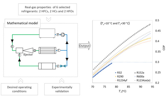
The objective of the present work was the assessment of two hydrofluoroolefins for the ejector cooling technology using a mathematical method. Aiming to an ejector air-conditioning system that works with a low-grade heat source, the working temperature ranges were chosen as follows: the generator temperature was from 65 to 95 °C, the condenser temperature was fixed at 30 °C. The temperature at the condenser was 10 °C since this ERS was used for air conditioning purposes. Working fluids’ assessment was based on several important parameters, such as the COP as a function of and , the required working pressure in a range of the generator temperature.
2. Mathematical Model of ECT
Referring to the basic ejector refrigeration cycle in
Figure 2, the system consists of a vapor generator (boiler), refrigerant pump, ejector, condenser, evaporator, and expansion valve. There are three auxiliary cycles for maintaining a generator, condenser, and evaporator at desired temperatures. The ejector’s working principle was described in works [
13,
14]. Please note that the letters in
Figure 2 denote for the thermodynamic state of the refrigerant at the outlet of each component, (G) for generator, (C) for condenser, (D) for diffuser, (E) for evaporator, (V) for expansion valve, (P) for refrigerant pump.
The coefficient of performance, COP, is the system performance. It is the ratio of evaporator heat energy
to the total energy used to drive the cycle, the generator heat energy
and the work of the pump,
Usually,
is negligible when compared to
and
. Hence, the above equation can be rewritten in the form of rates of heat flow:
The cooling capacity, CC, is then defined as
The ejector distributes the key performance factor, the entrainment ratio (ER), to the whole ejector cooling system. Therefore, the mathematical model of ERS was focused on the ejector. The constant-pressure mixing ejector generally has better performance than constant-area mixing ejector, as confirmed in [
11,
15]. Constant-pressure mixing ejector is an ejector that has the nozzle exit position (NXP) within the suction area (convergent part), in front of the constant area, as shown in
Figure 3.
The following assumptions were made to simplify the model: (i) Thermodynamic processes are adiabatic, except for heat exchangers, i.e., generator, condenser, evaporator. (ii) Flow inside the system is isentropic, with accounting coefficients regarding irreversible processes, frictions; these coefficients were obtained from literature and experimental work. (iii) There is a section within the mixing chamber, where the secondary flow reaches a velocity of sound (when the ejector, or generally ERS is at the critical mode); this section is called hypothetical throat, as proposed by Munday and Bagster [
13]. (iv) Primary and secondary flow are mixed at the hypothetical throat (cross-section 2); before section 2, they are separated flows, and after, they are completely mixed. (v) Velocities at two inlets and outlets of the ejector are neglected.
As seen in
Figure 3, the ejector is divided into several sections. For each section, conservation of mass, conservation of momentum, and conservation of energy are applied to define the state of that section. Thermodynamic properties of working fluids are called from the real gas database of the program Engineering Equation Solver (EES). Following text presents relations of one block to other section by section:
The thermodynamic model of the ejector was governed based on the work of Huang et al. [
16] and several assumptions from the work of Varga et al. [
14] and Munday and Bagster [
13].
The primary flow from the generator was assumed to have some degrees of superheat; the reason is superheated working fluid at the ejector will be in the form of gas (one phase ejector).
The working fluid inside the ejector is an ideal gas.
where
is the pressure of the primary flow.
Tg is the saturated temperature at pressure
.
is the degree of superheating of primary flow.
is the isentropic coefficient of the primary nozzle.
κ is the ratio of specific heats of given fluid, and R is the universal gas constant.
The relation between the nozzle outlet area
and throat area
is defined from the gas dynamic relation of Mach number at the nozzle outlet
The pressure at the nozzle outlet is defined by the total pressure of the primary flow and Mach number at the nozzle outlet by the following equation
When the system works at the critical point (see
Figure 4), the static pressure somewhere right behind the primary nozzle outlet
is approximately equal to the pressure at the secondary inlet
. For simplification, Varga et al. [
14] assumed that:
For a given working fluid, the pressure at the secondary inlet to ejector is a function of evaporator temperature, x is vapor fraction, “x = 1” indicates that the working fluid is at saturated gas state:
According to Munday and Bagster [
13], the hypothetical throat is the cross-section where the secondary flow chokes (reaches sonic condition) at the mixing chamber when the system works at critical mode. Huang et al. [
16] later assumed that the choke takes place at cross-section “2”, within the constant area section, as shown in
Figure 2. Thus, Mach number of secondary flow at the hypothetical throat (
) is assumed to be 1,
The pressure of the secondary flow at the hypothetical throat
is related with pressure at the secondary inlet
by following dynamic function for isentropic flow
At the hypothetical throat, the pressure of primary flow
is equal to the one of secondary flow
, according to [
13]
For a complete set of equations of the ejector, the reader is referred to the work of Huang et al. [
16].
Assuming that the pressure drop between diffuser and condenser is negligible, the rate of heat flow that is needed to transfer from the ejector cycle is,
where
and
are the enthalpy at the outlet of ejector and condenser, respectively.
The heat loss during the heat transfer between the ejector cycle and the auxiliary cycle at the condenser is counted by the coefficient .
varies by the ambient temperature, insulation, etc. Thus, it will be collated with results from experimental work.
The process in the expansion valve (V) was assumed as an adiabatic process. Thus,
. Also, it was assumed that heat loss at the evaporator is negligible because the evaporator is well insulated and the heat flow is continuous and steady. The cooling capacity is related to the secondary flow rate as the following equation
The pump power used to lift the pressure from the condenser pressure level to generator pressure (assuming that pressure from the outlet of the pump is equal to the pressure at inlet generator) is,
where the density
is a function of condenser temperature and pressure because it is the inlet valve of the pump. The coefficient at the pump
is used to count on friction loss.
The required rate of heat flow at the generator is then calculated by
where the generator coefficient
is used to compute heat loss during the heat transfer process from the solar collector cycle to the ejector cycle. The enthalpy at the pump outlet
hp is the sum of the enthalpy at the condenser outlet and the enthalpy generated by the pump
Thermodynamic properties at each stage of the whole cycle are called from the real gas database.
3. Refrigerant Selection
Working fluids should satisfy the criteria for system performance, environmental safety, economics. Thermodynamic properties of refrigerants are the most cared factors by researchers when choosing working fluid for the ERS. They must have low environmental impacts, meaning low GWP and ODP. They should be non-toxic, non-corrosive, chemically stable, and non-explosive.
In this study, six refrigerants were selected for the assessment. Some common HFCs were selected as references for comparison—R32 and R152a. They have an acceptable GWP index, inexpensive, non-toxic. Therefore, it is recommended as a substitution for refrigeration systems in the refrigerant regulation 517/2014. R600a and R290 are natural refrigerants; they have favorable thermodynamic properties and low environmental impact. Nevertheless, they are flammable. Two HFOs, R1234ze(e) and R1234yf, are the fourth-generation refrigerants of halocarbons. Their most valuable properties are very low GWP and non-flammability.
Table 1 presents the important properties of the selected refrigerants. These properties directly influence the performance of the refrigerants and the use of them in regard to the refrigerant regulation. Although the ozone depletion potential (ODP) is one of the most important parameters for refrigerant qualification, it is not included in the table because all these working fluids have zero ODP. The other factors are shortly explained in the following text:
- -
Molecular weight
is an important factor that influences the system size at a given cooling capacity (CC) and working conditions. For a set of working conditions, the CC depends on
and
(see Equation (13)). Assume that the difference of
between working fluid is negligible, then the CC is a function of
only. Consider the equation of state of ideal gas below:
where V is the volume of working fluid in the gas state, M is molecular weight. Parameters
and
are constants as the assumptions. Accordingly, the higher the M is, the lower V is required. In other words, the system is more compact if the molecular weight of refrigerant is large. As it is shown in
Table 1, using HFOs as working fluid has a number of valuable aspects, such as:
- -
GWP of carbon dioxide is equal to 1 as it is chosen as the reference gas for defining GWP. GWP100 of gas tells us how much heat the gas traps in the atmosphere in 100 years compared to carbon dioxide.
- -
Safety class: According to the ASHRAE standard, hazardous is presented by a capital letter and a number. Toxicity is indicated by a capital letter: letter A—low toxicity, and B, high toxicity. Flammability is classified into four groups: Group 1—non-flammable, group 2—mildly-flammable, group 2L—lower-flammable, and group 3—high-flammable. R1234ze(e) and R1234yf are classified as lower-flammable; which is only considerable drawback of these HFOs.
- -
SSL is the Slope of the Saturated-vapor Line in the temperature-entropy (T-s) diagram. Isentropic expansion of a working fluid that has a negative slope of the saturated-vapor line may lead to a condensation [
16], which will affect the performance of the ejector. To avoid this issue, some degrees of superheat should be applied. The need for superheating depends on how negative the slope is. With a positive-slope refrigerant, the superheating is necessary as well, but with less intensity. For example, superheating was applied in an ERS with R600a, which has a positive-slope of saturated line, as a working fluid in the works of Varga et al. [
17,
18].
- -
of a working fluid is the latent heat ratio of that working fluid. It is defined by the following equation:
where
and
are enthalpy of saturated vapor and saturated liquid at the evaporator temperature. Similarly,
and
are enthalpy of saturated vapor and saturated liquid at the generator vapor, respectively.
- -
The critical pressure () of the critical point influences the required robustness of the system. The ejector cooling system obtains a preferable performance if the temperature of the driving heat source (the primary flow) close to the critical temperature (. Which implies that the critical pressure is mostly equivalent to the working pressure of the primary flow. A low critical-pressure refrigerant requires a less system robustness and a lower pressure-head pump; and thus, it is desirable.
5. Results and Discussion
5.1. The Entrainment Ratio and the Performance of the System
The entrainment ratio (ER) as a function of generator temperature is presented in
Figure 6. At the constant temperature of the condenser (30 °C) and evaporator (10 °C), the ERs increased with the generator temperature. At the
of 65 °C, entrainment ratios of all selected refrigerants reached around 25%, except R32. R32 was recommended as an alternative by regulation 517/2014 due to its availability and reasonable low GWP index. However, it did not have a desirable performance in ECT. ERs of R600a and R1234ze(e) were quite comparable with each other, and they were the highest among all others. ER of R1234yf was significantly higher than of R290, but their profiles with the change of generator temperature were very similar. Increasing further the
to over 95 °C apparently did not improve the ERs of these two refrigerants at all.
The performance of the system at various generator temperatures is shown in
Figure 7. The system COP is a product of ER and the ratio of enthalpy differences of the phase-change processes (via Equation (2)). As seen, the performance of R152a was the highest among all, while its ER was just an average value compared to others. A similar observation was found for the performance of R32, which was comparable to the performance of R600a. The reason was the latent heat that used to evaporate the liquid to the gas state at the evaporator (low temperature) was higher than the latent heat that used to change the refrigerant from liquid state to gas state at the generator (high temperature). When the
approached greater values (closer to critical temperatures), the required latent heat at the generator became even smaller. Thus, the denominator of Equation (2) became smaller, resulting in a higher COP. This observation gave us a thought that having a generator temperature close to the refrigerant’s critical temperature might yield better performance.
The performance of R1234ze(e) in the whole range of was favorable, it reached 45% at the of 95 °C. On the other hand, the COP of R600a was noticeably lower than the COP of R1234ze(e) due to the difference of latent heats of the evaporating process. Even though R1234ze(e) and R1234yf are isomers, the performance of R1234yf was clearly poorer than the other.
As a consequence, the required rate of heat flow at the generator for a fix cooling capacity of the ERS was a function of COP, as presented in Equation (2).
When required cooling capacity is constant, the change of COP is inversely proportional to . For each refrigerant, with a constant and (also constant and ), the COP generally is relative to and . Therefore, low means low COP, and low COP requires higher . In other words, in order to conduct a required entrained flow , higher primary flow is required when the primary temperature is low. It means that a larger ERS is required if we want to work with a “low-grade driven heat source”, thus higher investment is required. For example, the required of the 4 kW cooling capacity ERS with R600a as working fluid at of 60 °C (with 5K of superheat) was 33.5 kW; the corresponding value when = 80 °C (with 5K of superheat) was 12.1 kW, almost 3 times lower was needed with 20 K difference of primary working temperature.
5.2. Working Pressure
The working pressure is the most concerning factor in designing a refrigeration system generally. A system with high working pressure requires robust construction and durable equipment. Particularly, this statement is compelling for ERSs. The refrigerant pump is an example; typically, a refrigerant pump in an ERS is required to generate high working pressures at low flow rates. Such a pump is not easy to find in the market at the moment, especially the one that can generate a pressure of 20 bar and higher. In the scope of this paper, the pressure level at the primary inlet flow would be discussed as it is the highest, and thus, is the most significant to the system in the viewpoint of robustness. The primary pressures were defined from the required primary inlet temperatures, which are working conditions, inputs of the mathematical model.
As expected, the required primary pressures of the working fluids varied widely and increased with the generator temperature (via
Figure 8). The R600a showed its advantage in this aspect; the primary working pressure varied only from 9 bar to 18 bar as the
reached 95 °C. This was one of the reasons for many researchers to choose isobutane in their experimental systems, as discussed previously. The
of R1234ze(e) was reasonably good, in the range from 13 to 27 bar, about 33% higher than R600a. As mentioned earlier, a high-pressure range raises the demand for the system’s robustness and durability, such as a generator, condenser. These heat exchangers in an ERS were usually plate and frame compact heat exchangers, which have limits in handling high-pressure fluids.
R152a worked at a pressure range from 15 to 31 bar at the saturated temperature from 65 to 95 °C, roughly 68% higher than the R600a. R1234yf required a higher-pressure range than R152a by about 1.5 bar. The ERS system using R152a and R1234yf can be realized at the high initial cost due to the pressure limit of the commercial plate-and-frame heat exchanger.
R290 and R32, on the other hand, required very high working pressures, which most likely exceed the pressure range of a typical plate-and-frame compact heat exchanger. Therefore, such ERS is technically and economically very challenging, especially for the low-performance refrigerant like R32.
5.3. Area Ratio
The area ratio (AR) is the ratio of the mixing area
over the throat area of the primary nozzle
As mentioned, ejector geometry was defined based on the assumption that the secondary flow at the mixing chamber (sections 2–3 in
Figure 3) reaches sonic speed, and the primary flow at the outlet of the primary nozzle is neither over expansion nor under expansion flow but column-shaped. This means the nozzle works at the optimal state for given conditions, producing maximum efficiency.
The variation of AR presents the sensitivity of the optimal geometry at various working conditions. The higher the differences of AR, the worst the system performs when the actual operating conditions are different than the designed conditions. As shown in
Figure 9, the AR of R32 varied from 1.9 to 2.5 when the
went from 65 to 77.7 °C. We could say that the performance of R32 did not vary strongly when the generator temperature, or working conditions in general, varied from the designed (optimal) dimensions. On the contrary, the AR of R600a and R1234ze(e) varied from 3 to 7 when the generator temperature changed from 65 to 95 °C. It implies that the system would be sensitive to the actual operating conditions, no matter what the optimally designed geometry might be. Therefore, the system could be considered as less stable.
6. Conclusions
In this paper, the six selected working fluids were assessed based on three essential criteria: the coefficient of performance, the working pressure, and the sensitivity of optimal ejector geometry with working conditions.
The used mathematical model employed several coefficients to compensate for the isentropic and friction losses in the ejector cycle. The results indicated reasonable agreement when compared with a numerical model. More detail on model validation will be presented in our next study.
Overall, the HFC R152a and the HFO R1234ze(e) were the best performance refrigerants. The hydrocarbon R600a also offered promising performance. However, the flammability and the high-GWP-value of the hydrocarbon and HFC made HFO R1234ze(e) the only suitable choice.
Due to the diversity of working pressures, the required robustness of ERS significantly varies by different working fluids. The selections of the working pump and heat exchangers must be based on selected working fluids in this sense. The assessment on working pressure also showed that the three working fluids that have just been mentioned were best ones, from which R600a was the most favorable. R1234ze(e) also proved that it is a great candidate for ERS as well as for the refrigeration system in general. However, neither R152a nor R1234ze(e) showed the desired character in terms of system stability with a fixed ejector geometry. The solution for the issue is using a variable geometry, which is adjustable so that it can reach (or close to) optimal geometry for actual operating conditions.


