1. Introduction
The past decades have witnessed a booming expansion in scales, such as the emergence of the tens of megawatts wind turbines, which include two types of direct-drive and gearbox. Although the direct-drive wind turbines eliminate the inconvenience of a gearbox and its possible troubleshooting, the scarcity and instability of materials [
1,
2], the complexity of cooling system [
3,
4,
5], and the high failure rate of full-power converter [
6,
7,
8] lead to the fact that the direct-drive wind turbines cannot be popularized.
The gearbox has played an important role in the development of the large-scale wind turbine, as shown in
Table 1.
Table 1 shows that 70 percent of the top ten largest commercial wind turbines [
9] are equipped with a gearbox. Despite its wide application in wind turbines, the low reliability of the gearbox causes a series of problems, including high failure rate, long downtime, and short life of the whole machine [
10]. According to statistics of wind turbine component failures, the failure of bearing contributes to up to 50% of the gearbox failure [
11]. The dramatic increase in the rotor weight of large wind turbines has led to a sharp increase in the working load of main bearing and low-speed planetary gear bearing. In addition, it is difficult to provide them with good lubrication in the low-speed and heavy load operating conditions [
12]. In addition, the damage of planetary gears is also a key factor affecting the life of gearbox. Because the low speed stage planet gears have a low rotational speed, the forces acting on the gears are quite large. Furthermore, the planet gears always bear bi-directional forces due to their engagement with both ring and sun gears; thus, fatigue fracture failure is prone to happen [
13].
From the above analysis, in order to improve the service life of a gearbox, it is essential to reduce the force acting on the gear teeth and bearing due to the transmission of huge torque. Power splitting technology plays a significant role in reducing the force and improving the life and reliability of gearbox [
14]. In view of the new structure of the double-rotor wind turbine (DRWT), it is in fact a kind of novel structure of power splitting, because the large torque transmitted by a single rotor is divided into two parts, which are transmitted by two rotors respectively and finally can be combined. However, the double-rotor structure of DRWT may increase the structural complexity of the wind turbine, which brings greater challenges to the design. In any case, the reduction of the force and the improvement of the life of the gearbox brought by the DRWT is particularly significant.
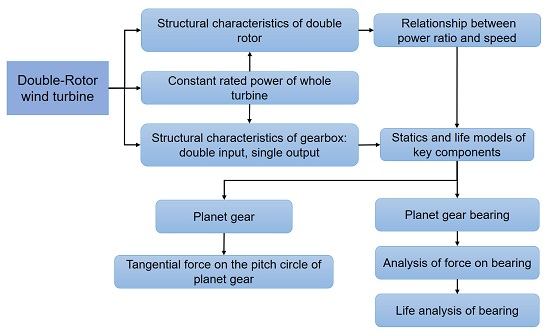
In this study, an investigation was carried out to explore the gearbox structure of a DRWT and to prove that DRWTs have significant research value in the field of wind power development. Under the premise of constant power of 5 MW, nine different integer power ratios were set for the double input of the double rotor since the power distributed to each rotor is not constant, that is, the power ratio of two rotors could be variable. The stress of planetary gears and their bearing with a higher failure rate is analyzed. Then, the tangential force of the planetary gear, as well as the force and life of the planetary gear bearing, are calculated and compared with the traditional single-rotor wind turbine (SRWT). The organization of this paper is as shown in
Figure 1.
The advantages of the DRWT structure to the gearbox are highlighted: (1) by dividing the high power into two parts and input simultaneously, the transmission torque and forces of gears and their bearings are effectively reduced, and the service life of the bearing is improved; (2) in actual design, different power ratios of double rotors can be selected according to the specific conditions of manufacture, installation, operation and maintenance; (3) the blade length can be shortened to varying degrees and the moment balance of nacelle can be achieved.
The remaining content of this paper is as follows: In Part 2, the related research is introduced, including research on the gearbox of wind turbines and the DRWT. Part 3 describes the structure characteristics and working principle of the gearbox in a DRWT. According to the principle of force and moment matching in planetary transmission, the relationship between the power ratio and the rotational speed of double input is determined. Part 4 establishes the statics model of the force and life of planetary gears and their bearings in the gearbox of a DRWT at different power ratios. Part 5 shows the analysis of the calculation results of Part 4 and compares the results with those of the traditional single-rotor wind turbine (SRWT) planetary gears and their bearings. Part 6 is the summary and conclusions of this paper.
2. Related Work
A lot of research has focused on the gearbox of wind turbines recently, including dynamic response analysis of key components of a gearbox [
15], reliability monitoring models of a gearbox to improve the life of a wind turbine [
16], and time domain analysis of gear contact fatigue under dynamic conditions [
17]. In order to study the relationship between the acceleration of a single pile foundation and the load effect of the transmission system of an offshore wind turbine, Nejad et al. [
18] established a model of a NREL 5 MW offshore wind turbine. The load effect of the transmission system was analyzed. The results demonstrated that the life of inner components of the gearbox was independent of the maximum axial acceleration of single pile, and the life of the first main bearing was related to wind speed. Relevantly, the life of the second main bearing was independent of the wind speed. Molinas et al. [
19] proposed a quasi-statics equivalent circuit system based on control technology in order to prolong the service life of a gearbox which can reduce the mechanical stress of the transmission system by controlling the transient electromagnetic torque of the generator, thereby improving the service life of the gearbox. The applicability of this method in wind farms was discussed. Based on fault tree and Bayesian network analysis, Jin et al. [
20] established the fault model of wind turbine gearboxes, including contact fatigue pitting and bending fatigue fractures of gear teeth, and obtained the reliability and weakness of the gear transmission system. Bielecki et al. [
21] discussed the wind loads on the gears and bearing of the wind turbine drive system, constructed the wind speed generating module and spindle speed function model, and proved the correctness of the proposed method by comparing with experimental data.
In recent years, research based on wind turbine gearboxes mainly concentrates on these aspects: improving the manufacturing and assembly accuracy of the gearbox, investigating the influences of assembly errors on the dynamic characteristics of the gearbox [
22]; modifying the tooth profile of gears to reduce vibration and noise to extend their service life [
23]; the influence of sun gear’s profile error on dynamic responses of the gearbox [
24]; micro-pitting of the gears and white etching cracking of the bearing [
25,
26]; as well as the development of the flexible bearing and other load-sharing technologies [
27].
Furthermore, much research focuses on the double-rotor wind turbine (DRWT). Kumar et al. [
28] studied the power generation performance of a DRWT. By comparing the two schemes, the optimal criteria for the performance of a DRWT and the effects of blade geometry, blade back pressure, and flow efficiency on output power were obtained. Researchers [
29] at Iowa State University studied the aerodynamic and wake characteristics of a DRWT during co-rotating and counter-rotating in a wind tunnel experiment. The diameter of the DRWT was equal, and the spacing was D/4. It was concluded that the power and wind load generated by the DRWT are higher than that of the traditional single-rotor wind turbine (SRWT). It was found that the counter-rotating wind turbine can capture more wind energy than the co-rotating wind turbine. Wang et al. [
30] used a DRWT and a SRWT to form a unit. The results show that when the distance between two wind turbines is greater than 4D, a SRWT in the downwind direction of a DRWT can generate more power than a SRWT in the downwind direction of another SRWT. In this paper [
31], the aerodynamic performance, wind load, and power of a DRWT and a traditional SRWT are experimentally compared in wind tunnels under the same conditions. The results show that the power generated by a DRWT is 7% higher, but the complexity of their structure also brings about larger wind load (more than 16%) and more complex wake features. Rosenberg et al. [
32] found an optimum design for maximizing the power factor of a DRWT at one operating point by solving the RANS (Reynolds Averaged Navier-Stokes) equation. The optimum distance between the two rotors was determined to be 2D, and the optimum tip speed ratio of the auxiliary rotor was six using the optimum parameter method. Thus, the power factor of the wind turbine could be increased by about 7%. Slew et al. [
33] firstly experimented the aerodynamic performance of DRWT blades. On this basis, the rotors of NREL Phase VI were scaled and placed in the upwind, and the rotor of NREL UAE Phase VI was placed in the downwind to form a DRWT. The distance between the two impellers is half of the diameter of the rotor of NREL UAE Phase VI. Compared with the traditional SRWT, the DRWT can generate 16% more power.
The above research concentrates on the improvement of the power coefficient, capturing more wind energy, and the aerodynamic performance and wake characteristics of DRWTs. There is little research on the transmission system and gearbox of a DRWT. Perhaps this is because the new structure of the double rotor in wind turbines has recently become a research hotspot. Therefore, the calculation and analysis of the force and life of the double-rotor gearbox are carried out in this study to prove the research value of DRWTs.
3. Description of Gearbox Structure and Input Rotational Speed of DRWT
3.1. Structure and Characteristics of Gearbox in DRWT
The gearbox structure of a DRWT is similar to the traditional SRWT. The difference between them is that the gearbox of a double rotor has double input and single output, while the gearbox of a single rotor has single input and single output. This section describes the structural characteristics of a DRWT gearbox.
3.1.1. Structure of Gearbox in DRWT
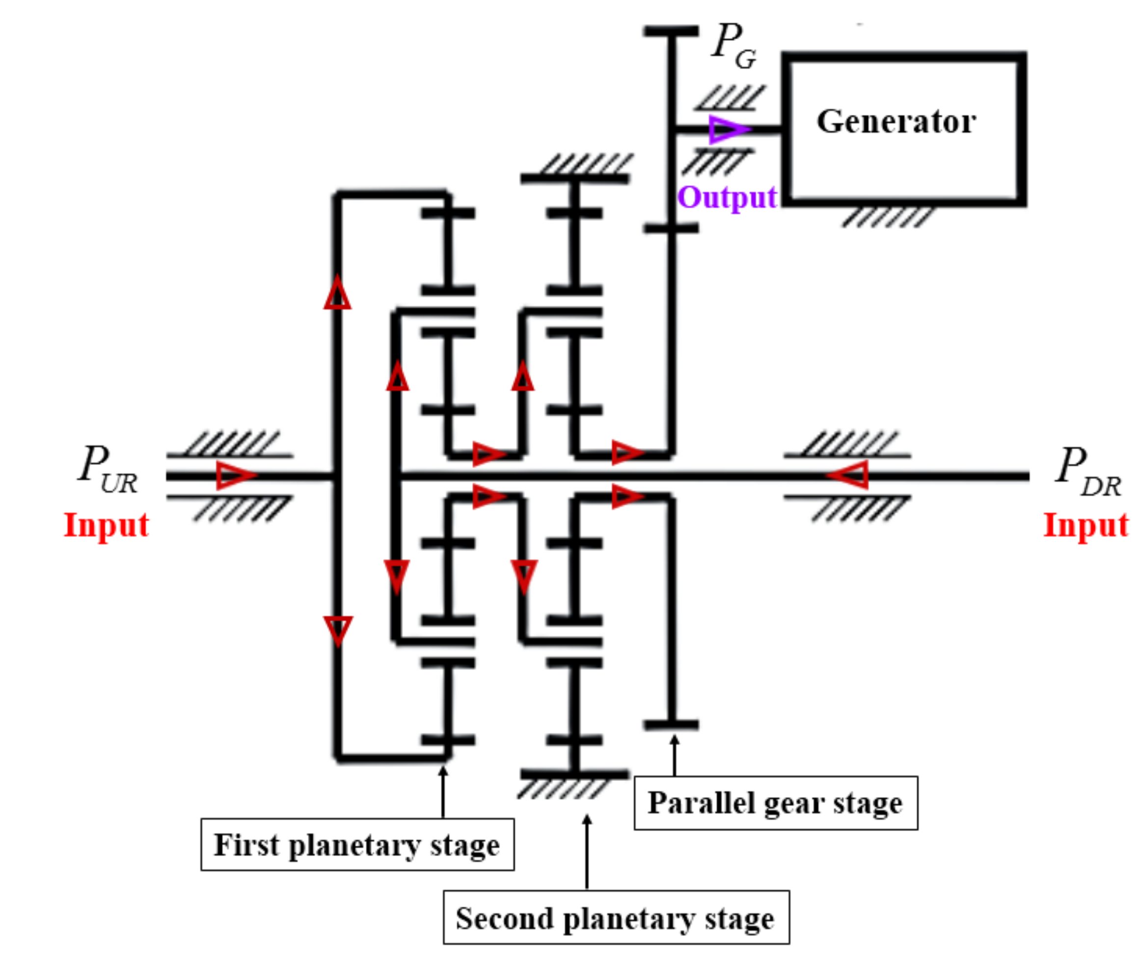
The novel gearbox structure diagram of the gearbox of DRWT is shown in
Figure 2. It is composed of two planetary gear stages and one parallel gear stage. The first planetary stage adopts a differential planetary gear drive, of which the ring gear connected with the upwind rotor (UR) and the planet carrier linked to the downwind rotor (DR) are chosen as two inputs, and the sun gear as output. The second planetary stage adopts standard type 2Z-X (A) planetary transmission, with the planet carrier as input and sun gear as output.
Figure 3 shows the power flow direction of the gearbox. The two input powers
and
meet on the planet gears in the first planetary stage in the direction indicated by the red arrow and output to the planet carrier of the second planetary stage through the sun gear, then output to the parallel gear stage through the sun gear of the second planetary stage, and finally output the power
to the generator in the direction indicated by the violet arrow.
When working, the power of the whole turbine is divided into two parts, which are respectively transmitted from the upwind rotor (UR) and downwind rotor (DR) to the sun gear of the first planetary stage, and then to the second planetary carrier. Finally, the power is transmitted to the parallel gear stage after the speed is increased. In order to simplify the calculation, the gearbox of the NREL 5 MW offshore wind turbine is selected as the reference in this paper, of which the ring gear and the planet carrier of the first planetary stage are carried as two inputs. The parameters of gears and other information subject to NREL 5 MW [
34] are as shown in
Table 2.
3.1.2. Characteristics of Gearbox in DRWT
In essence, the single rotor is divided into two rotors in the DRWT, that is, the wind power originally absorbed by the single rotor is absorbed through two rotors separately instead. Therefore, the power of the whole turbine needs to be divided into two parts. It is assumed that the power of the DRWT and SRWT is constant, there is a relationship of power ratio between the two rotor’s absorbed powers in the DRWT, and this power ratio is defined as the ratio of wind power absorbed by the UR and DR, which is denoted by the symbol . The power of these two parts is transmitted to the first planetary transmission through two rotors. During the transmission process, the forces acting on the gear teeth and bearing will also be affected by different power ratios. Therefore, when analyzing and calculating the forces of the gears and bearings, the factor of power ratio needs to be considered.
Obviously, the DRWT reduces the torque transmitted by the ring gear and the planet carrier of the first planetary stage through force sharing, and the forces borne by the planet gears and its bearing are also significantly reduced, which increases the life of the bearing and gearbox to some extent and prolongs the life span of the whole wind turbine. At the same time, the originally longer blade is divided into two sections to make two rotors, which reduces the size of the blades and the difficulty of manufacturing and transportation. The control method of this double input gearbox is more flexible, but it can achieve the goal of power maximization by controlling the rotation speed of the two rotors, that is, controlling the double factors to achieve the single goal. It can be seen that the DRWT is of great significance to the development of the wind power industry.
However, the DRWT divides one rotor into two rotors, which increases the complexity of its structure and raises the requirements of foundation of the tower. Therefore, these problems may be brought into consideration when discussing the design and application of the DRWT.
3.2. Relationship between Power Ratio and Input Rotational Speed
There is a restriction relationship between the double input rotational speeds of the DRWT, which needs to be determined according to the torque matching, force balance, power ratio and other factors of the planet gears in the planetary transmission.
The ratio between two input powers of DRWT is expressed by symbol
, that is, the power ratio:
The power of the whole turbine is
, so there is:
Combined with the above two equations, the power transmitted by the two rotors can be solved.
where
and
are the power transmitted by the UR and DR respectively.
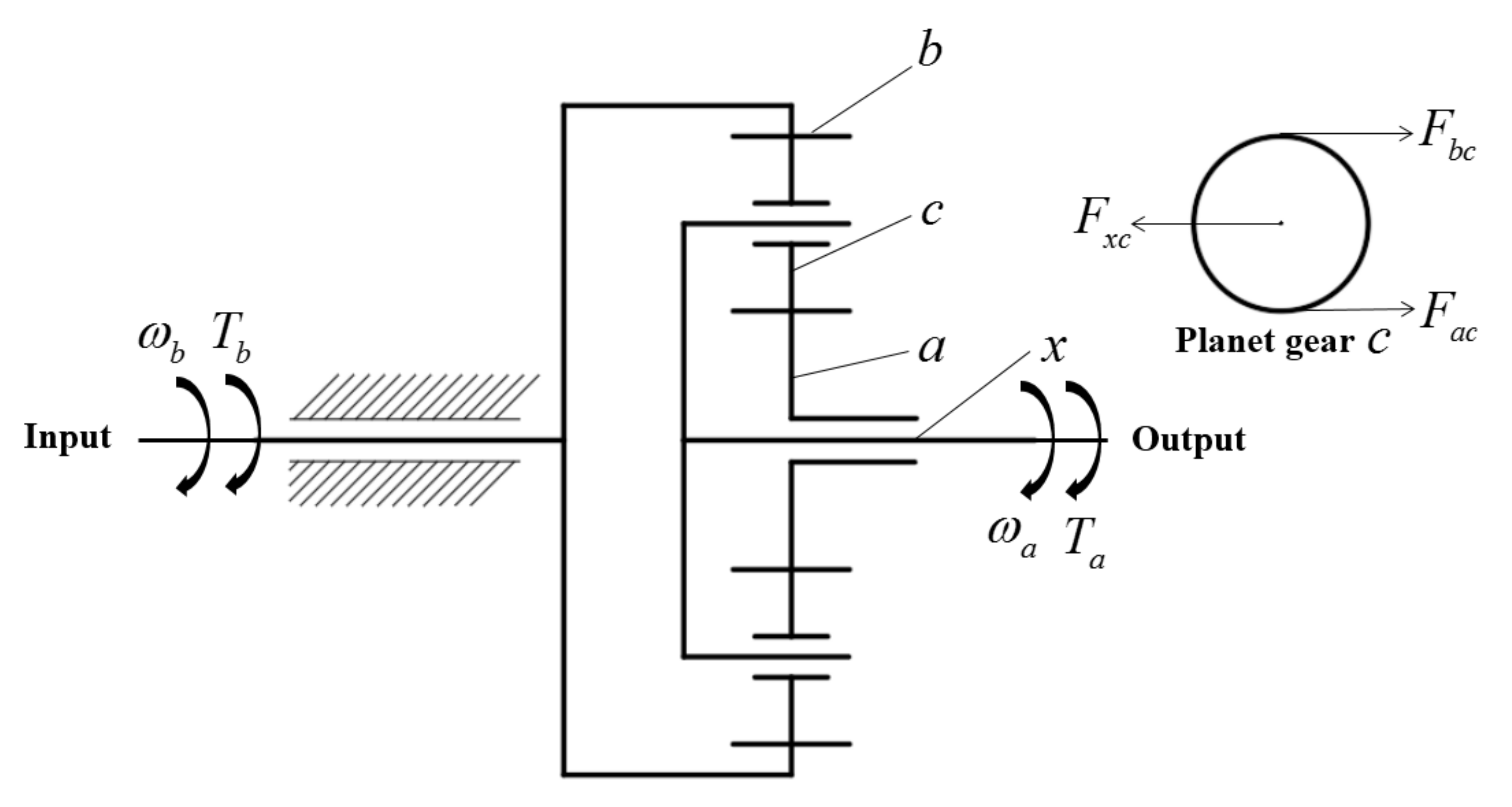
Figure 4 is a detailed annotation of the structure of the first planetary transmission in
Figure 1. Here, all gears in planetary transmission are cylindrical spur gears, so the axial force is not considered. The tangential force on planet gear
comes from ring gear
, planet carrier
and sun gear
, as follows [
35].
The tangential force of ring gear
acting on planet gear
:
The tangential force of planet carrier
acting on planet gear
:
The tangential force acting on planet gear
by sun gear
:
The relationship to be satisfied among the three forces:
When the double input rotational speed, torque of the ring gear and planet carrier of the DRWT are substituted into Equations (5)–(7), we can get equations as follows:
where
is the number of planet gears;
and
are the rotational speed of ring gear
and planet carrier
respectively;
and
are the pitch circle diameters of the sun gear and ring gear respectively;
is the rotational radius of the planet carrier;
,
and
are the torques transmitted by the ring gear
, planet carrier
and sun gear
respectively;
is the rated power of whole turbine;
is the ratio of the power transmitted by the UR and DR.
Combining Equations (8)–(12), the relationship of rotational speed between the ring gear and the planet carrier can be obtained:
Meanwhile, these two rotational speeds also need to meet the requirements of blade tip linear speed [
36]. After sorting out the above formulas, it is concluded that the conditions to be satisfied by
and
are as follows.
(1) Restrictive relationship: .
(2) Linear speed restriction of blade tip:
where and represent the speed and radius of the wind rotor respectively.
By substituting the geometric information of the NREL 5 MW wind turbine into the second condition mentioned above, it can be obtained that the rotational speed of wind rotor should meet the requirement .
Considering the influence of power ratio
, the nine integer ratios between
,
and
can be determined, as shown in
Table 3.
By observing
Table 3, it is found that when
, the rotational speed of the ring gear
, which already exceeds the range of the blade tip linear velocity, so the force and life calculation under this power ratio will not be discussed later.
In order to ensure that the final output rotational speed of the whole gearbox can match the rotational speed of the synchronous generator, it is necessary to ensure the output rotational speed of the parallel gear stage (that is, the speed of the sun gear of the second planetary stage) after the two-stage planetary transmission being basically constant. Different input speeds corresponding to the nine power ratios in
Table 3 were calculated to get the rotational speed of the sun gear of the second planetary stage, as shown in
Table 4 (the units of rotational speed in the table are all rpm).
In
Table 4, the rotational speed of the sun gear of the second planetary stage is basically constant around 590 rpm. Except for the power ratio of 7/3 and 8/2, the maximum difference between the rotational speed of the sun gear for the six power ratios and 590 rpm is only 2.03%, so it can be considered to be basically constant. When the power ratio is 7/3 and 8/2, the speed difference is 5.12% and 11.29% respectively, which is relatively quite large. Therefore, we should pay attention to this problem when designing double rotors and choosing the power ratio. It’s better to avoid these two power ratios as far as possible.
4. Force Model of Planet Gear and Life Model of Its Bearing of DRWT
The models established in this section are all theoretical calculation models. Before modeling, four prerequisites need to be explained:
(1) For each power ratio, the gearbox of the DRWT is in standard working condition.
(2) The information of the components in the DRWT gearbox is the same as that of a traditional NREL 5MW.
(3) Compared with the SRWT, the DRWT has the same aerodynamic performance and operating and lubrication conditions, except for the different structure of the double rotor and input of the gearbox.
The existing design of the gearbox in a NREL 5 MW wind turbine is adopted in this paper: two-stage planetary and one-stage parallel, as shown in
Figure 5.
When calculating the force and life of the planet gear and its bearing of the DRWT, the ring gear of the first planetary stage is unfixed as one input and the planet carrier as the other input, as shown in
Figure 2.
4.1. Force Model of Planet Gear of DRWT
The power transmitted by the first planetary stage is output from the sun gear to the planet carrier of the second planetary stage, which is further accelerated and then transferred to the parallel gear stage.
In the first planetary stage, the ring gear is connected to the UR, and the planet carrier is connected to the DR. Both serve as double inputs and the sun gear as output. Similarly, the tangential force on planet gear comes from ring gear , planet carrier and sun gear .
Assuming that the two input rotational speeds are rated, the input torques are
The tangential force on the pitch circle of the first planet gear is
The tangential force on pitch circle of the second planet gear is
where
and
are the number of planet gears of the first and second planetary stage respectively;
and
are the input rotational speeds of the planet carrier and ring gear in the first planetary stage; and
and
are the diameters of the pitch circle of sun gears of first and second planetary stage respectively.
4.2. Force and Life Model of Planet Gear Bearing
Force on the bearing of first planet gear:
Force on the bearing of second planet gear:
The formula of bearing life is
where
is the rotational speed of bearing,
is the rated dynamic loads of bearing, and
is the bearing force.
When calculating the bearing life of the planet gear of a DRWT, in order to more intuitively compare it with the bearing life of a SRWT, we calculated the ratio of the bearing life of a DRWT and SRWT , which is equivalent to the dimensionless of the bearing life of a DRWT. The following calculation formulas are dimensionless.
Bearing life of the first planet gear of DRWT:
Bearing life of the second planet gear of DRWT:
where
,
and
are the rotational radius of the planet carriers of the first and second planetary stage respectively;
is the input rotational speeds of the planet carrier of the SRWT;
and
are the rotational speeds of the bearings of the first and second planet gear stage of the DRWT respectively;
and
are the rotational speeds of the bearings of the first and second planet gear stage of the SRWT respectively;
is the life index of the bearing, the value for the ball bearing is 3, and the value for the roller bearing is 10/3.
According to literature [
34], information related to the bearing of the planet gear can be obtained by searching the SKF (Svenska Kullager-Fabriken) bearing manual [
37], as shown in
Table 6.
Where represents cylindrical roller bearing, and represent the rated static load and the rated dynamic load of bearing respectively.
5. Analysis of Force of Planet Gear and Life of Its Bearing of DRWT
It is necessary to calculate the force and life of the gearbox of a DRWT at different power ratios. In this paper, the power ratio is analyzed by a series of integer values. takes each integer ratio between 1/9 and 8/2 respectively.
5.1. Analysis of Force on the Planet Gear of DRWT
It could be found that the force model of planet gear in
Section 4.1 is related to the two input rotational speeds.
According to
Table 5, combining with the values of the two input rotational speeds in
Table 3, the calculated tangential force on the pitch circle of the planet gear is arranged as shown in
Table 7.
As can be seen from
Table 7, at any power ratio, the tangential force on the pitch circle of the planet gear of the first stage is larger than that of the second stage, which is related to the increase of the rotational speed of the second stage.
With different power ratios, the tangential force on the pitch circle of the planet gear has little change. When the power ratio is taken as and , which is relatively larger, the force will become greater, which is not conducive to the improvement of gearbox life. Therefore, when choosing the power ratio, the two values should be avoided.
5.2. Analysis of Force and Life of Planet Gear Bearing of DRWT
As far as the statics model in
Section 4.2, the force and life of the planet gear bearing of the first stage is related to power ratio
, while the force and life of the second stage is related to the two input rotational speeds.
When calculating the force and life of planet gear bearing, it is necessary to calculate the values of some parameters first. The detailed calculation process is shown in
Figure 6. Combining with the equations in
Table 5, the values of these parameters are calculated and listed in
Table 8.
Table 8 shows that the power ratio
has little influence on the torque transmitted by the planet carrier and ring gear, or the rotational speed of the bearing in the two-stage planetary transmission. When the power ratio
is larger, such as
and
, the torque is slightly increased.
In
Table 9, the force and life of the planet gear bearing corresponding to the different power ratios are calculated.
The bearing life of
and
in
Table 8 is dimensionless compared with the bearing life of a SRWT when the power of the whole turbine is constant. As can be seen from
Table 9, with the increase of power ratio
, the bearing force and life of the planet gear of the first planetary stage fluctuate around 810 kN and 4.5 respectively. The bearing force and life of the second planetary stage fluctuate around 320 kN and 3.7 respectively. At the power ratio of 7/3 and 8/2, the bearings of the two-stage planet gears are subjected to larger force and have smaller life relatively, which indicates that the last two larger power ratios should be ignored in design.
5.3. Comparison of Force and Life of Gearbox in DRWT and SRWT
In this section, the calculation results of
Section 5.1 and
Section 5.2 are plotted and compared with the results of a traditional SRWT. It is more intuitive and clear that the DRWT plays a significant role in improving the force and life of the gearbox. In addition, the calculation results of the DRWT are drawn separately to illustrate the relationship between the power ratios and the force and life of the gearbox.
5.3.1. Comparison of Torque of Planet Carrier and Ring Gear between DRWT and SRWT
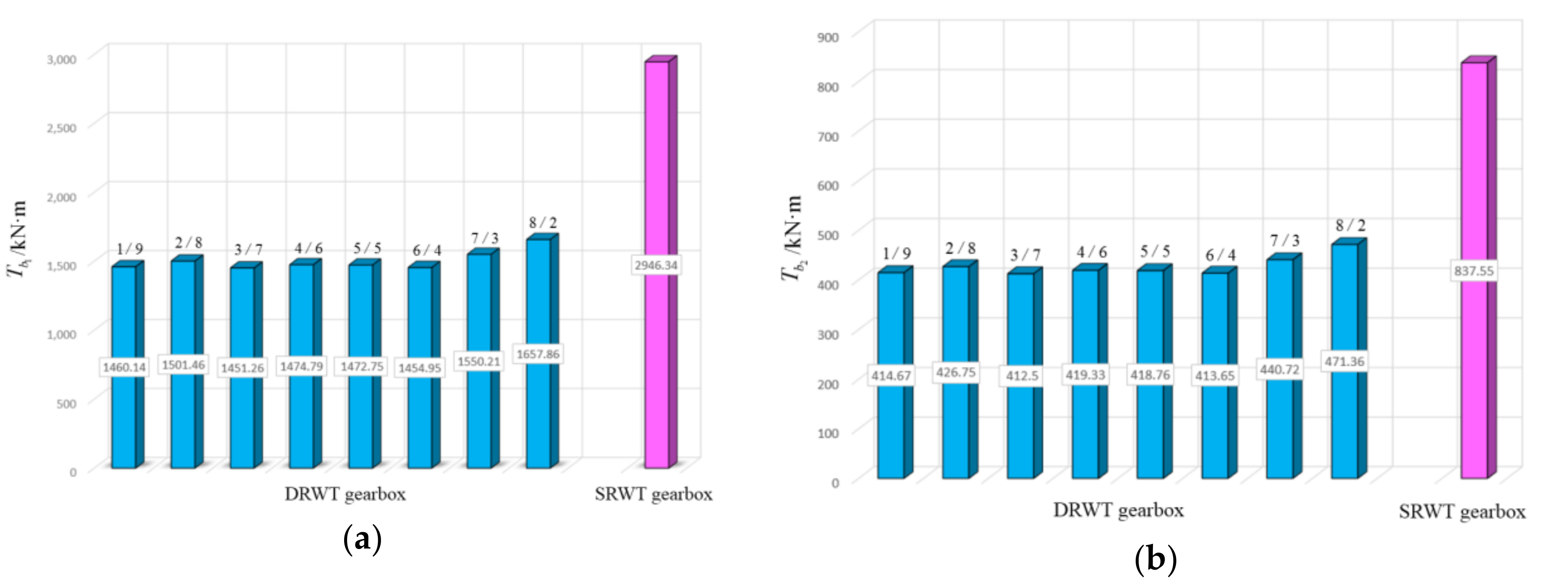
Figure 7 and
Figure 8 show the torque transmitted by the planet carrier and ring gear in the two-stage planetary transmission respectively.
As can be seen from
Figure 7 and
Figure 8, in two-stage planetary transmission, when the power ratio
varies, the torque transmitted by the planet carrier of the first and second stage fluctuate in 1975 kN·m and 500 kN·m respectively, while the torque transmitted by the ring gear of these two planetary stages fluctuate in 1475 kN·m and 420 kN·m respectively. It is easy to see that the torque transmitted by the planet carrier and ring gear of the first stage is about four times and two times that of the second planetary stage with high rotational speed respectively. Compared with a SRWT, the torque transmitted by the planet carrier and ring gear of the DRWT is reduced by about half as much as in the SRWT.
Comparing the torque of ring gear in two-stage planetary transmission, it is found that the torque of the planet gear of the second stage is slightly more than one quarter of that of the first planetary stage, which is perhaps also related to the speed increase of the second planetary stage.
In general, no matter what the torque of the planet carrier or ring gear is and no matter the first planetary stage or the second planetary stage is, in a DRWT, the torque is reduced to half that of a SRWT, indicating that the double-rotor structure of a DRWT can significantly reduce the torque of the planet carrier and ring gear in the gearbox.
5.3.2. Comparison of the Tangential Force on the Planet Gear between SRWT and DRWT
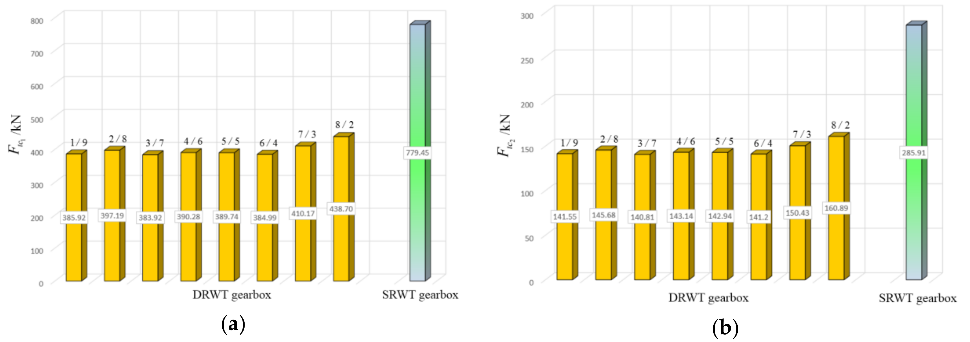
It could be found that the tangential force on the pitch circle of the planet gear in the DRWT is nearly half lower than that of the SRWT in
Figure 9.
In the DRWT gearbox, the tangential force on the pitch circle of the planet gear of the first and second planetary stage fluctuate around 390 kN and 145 kN respectively, except for the power ratios 7/3 and 8/2. By observing
Figure 9a,b, no matter whether for the SRWT or DRWT, the tangential force on the pitch circle of the planet gear of the second stage is smaller than that of the first stage by more than half. This is caused by the increase of rotational speed and the decrease of torque transmitted in the second planetary stage.
Compared with a SRWT, the double-rotor structure of a DRWT can effectively reduce the force on the pitch circle of the planet gear in the gearbox. If it is required to lower the force on the planet gear in actual design, avoiding the larger power ratios 7/3 and 8/2 can be accepted.
5.3.3. Comparison of Life of Planet Gear Bearing between DRWT and SRWT
Figure 10a,b show the bearings life of the planet gears of the first and second stage respectively. In the figure, the vertical axis represents the life span of a DRWT relative to a SRWT at different power ratios, which is dimensionless. The two figures are very similar on the whole. The difference is that the life span of the planet gear bearings of the first and second stage are 3–5 times and 2–4 times that of the SRWT respectively, which perhaps is related to the change of lubrication conditions caused by the increase of the rotational speed of the planet bearing of the second stage.
For the DRWT, it could be found in more detail from the two figures that the bearing life span of the first and second planetary stage fluctuate about 4.5 and 3.6 relative to the life span of the SRWT, which directly proves that the structure of the DRWT brings the superiority of improving the bearing life of the gearbox.
5.3.4. The Relationship between the Power Ratio and the Force and Life of Gearbox in DRWT
The line chart in
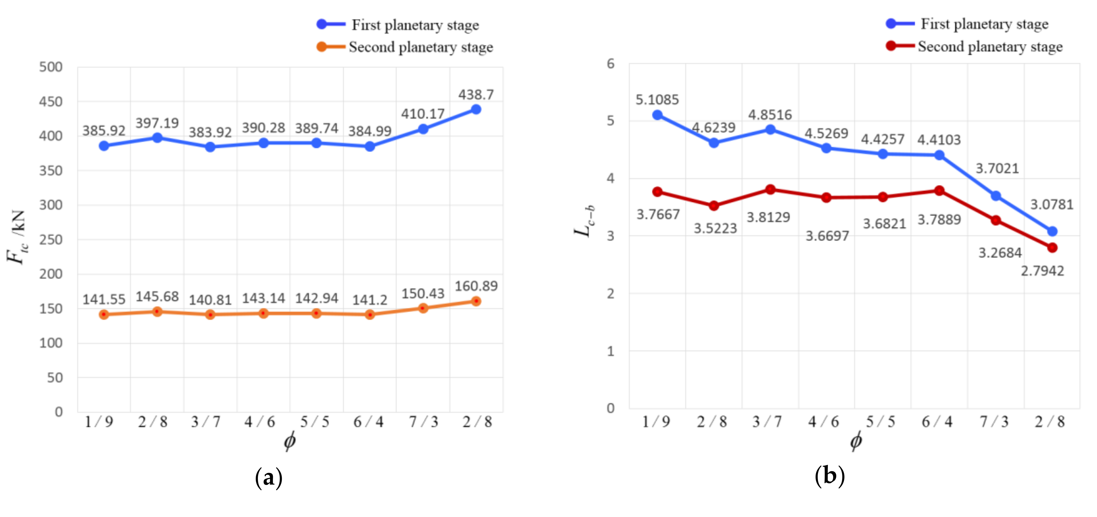
Figure 11 shows the relationship between the power ratio and the force and life of the DRWT gearbox.
Figure 11a shows the tangential force on the pitch circle of the planet gear in two-stage planetary transmission. Obviously, the two kinds of tangential forces have a small range of variation, only when the power ratio is larger than 6/4, such as 7/3 and 8/2, is there a tendency to increase. In other words, the tangential force on the pitch circle of the planet gear of the first and second planetary stage fluctuate around 390 kN and 145 kN respectively. When the power ratio is taken as 7/3 and 8/2, these two tangential forces will increase to more than 400 kN and 150 kN. In addition, the tangential force of the first planetary stage is more than twice that of the second stage. Because the power of the whole wind turbine is directly transmitted to the first planetary stage and output to the planet carrier of the second planetary stage through the sun gear of the first planetary stage. During this process, the torque of the second planetary stage will be reduced after the increasing of the rotational speed, so the force will also be reduced.
Figure 11b shows the dimensionless life of the planet bearing at different power ratios. On the whole, the bearing life of the first planet gear is a little longer than that of the second planet gear. This may be related to the increasing of the rotational speed of the bearing of the second planet gear, which results in poor operating condition for the bearing of the second stage.
Simultaneously, with the increase of the power ratio, the bearing life of the two-stage planet gear tends to decrease, especially when the power ratio is larger than 6/4, whereby the decrease is more obvious. It could also be said that when the power ratio is lower than 6/4, the life of the planet gear bearing has a small change, fluctuating around 4.6578 for the first planetary stage and 3.7071 for the second planetary stage. However, as the power ratio increases to 7/3 and 8/2, the life of the planet gear bearing significantly decreases to below 4.6578 for the first planetary stage and 3.7071 for the second planetary stage. This suggests that we should avoid choosing larger power ratios, such as 7/3 and 8/2, when designing double rotors and selecting their power ratios.
Furthermore, when the power ratio is small, such as 1/9, the bearing life is longer, but at that moment, there is too much difference between the power transmitted between the two rotors, which causes an imbalance in structure and a mismatch in performance. Therefore, when designing a double-rotor wind turbine, the intermediate values with little difference of should be selected as the appropriate power ratio.
6. Conclusions
In this paper, taking the differential gearbox of an existing DRWT as the research object, we divide the constant rated power of the whole wind turbine into two parts, according to different ratios, and distribute them to two inputs of the gearbox. The statics model of the planet gear and its bearing in the gearbox of the DRWT was established. Then, the force and life of the planet gear and its bearing with a high failure rate in the gearbox were calculated to compare with traditional SRWT, and the following conclusions can be drawn:
(1) The force on the gearbox of the DRWT is nearly half smaller than that of the SRWT, including the tangential force on the pitch circle of the planet gear and the force of the planet gear bearing.
(2) The service life of the planet gear bearings of the first and second stage of the DRWT are 3–5 times and 2–4 times that of the SRWT respectively.
(3) In the gearbox of the DRWT, the power ratio has little influence on the tangential force of the planet gear and the force of its bearing, which fluctuate around a constant value respectively. However, larger power ratios (such as 7/3 and 8/2) cause an increase of tangential force on the pitch circle of the planet gear and bearing force. As for the service life, with the increasing of the power ratio, the bearing life of the two-stage planet gears tend to decrease, especially when the power ratio is larger than 6/4 (such as 7/3 and 8/2).
(4) The DRWT is proved to have the advantages of reducing the force of the planet gear and its bearing in the gearbox and improving the life of the bearing. At the same time, the double-rotor structure divides the long blade of the SRWT into two sections, which can reduce the difficulties of manufacture and transportation of blades.
In addition to the above conclusions, when designing the size and structure of the double rotor of the DRWT, in order to reduce the force on the gearbox and improve its service life, we should avoid choosing larger power ratios of 7/3 and 8/2 so as to make the difference between the powers of the two rotors as little as possible from the perspective of power balance.


