Integrated Analysis of Influence of Multiple Factors on Transmission Efficiency of Loader Drive Axle


1
School of Mechanical and Automotive Engineering, ZhaoQing University, Zhaoqing 516260, China
2
School of Mechanical and Automotive Engineering, South China University of Technology, Guangzhou 510640, China
3
Departments and Graduate Institute of Electronic Engineering, National Formosa University, Yulin 63202, Taiwan
*
Authors to whom correspondence should be addressed.
Energies 2019, 12(23), 4540; https://doi.org/10.3390/en12234540
Submission received: 2 October 2019
/
Revised: 13 November 2019
/
Accepted: 22 November 2019
/
Published: 28 November 2019
(This article belongs to the Special Issue Selected Papers from IEEE ICKII 2019)
Abstract
:In this study, a loader drive axle digital model was built using 3D commercial software. On the basis of this model, the transmission efficiency of the main reducing gear, the differential planetary mechanism, and the wheel planetary reducing gear of the loader drive axle were studied. The functional relationship of the transmission efficiency of the loader drive axle was obtained, including multiple factors: the mesh friction coefficient, the mesh power loss coefficient, the normal pressure angle, the helix angle, the offset amount, the speed ratio, the gear ratio, and the characteristic parameters. This revealed the influence law of the loader drive axle by the mesh friction coefficient, mesh power loss coefficient, and speed ratio. The research results showed that the transmission efficiency of the loader drive axle increased with the speed ratio, decreased when the mesh friction coefficient and the mesh power loss coefficient increased, and that there was a greater influence difference on the transmission efficiency of the loader drive axle.
1. Introduction
The loader is widely used as a construction machine, and the drive axle is an assembly of the loader drive system. The loader drive axle is mainly composed of a main reducing gear, a differential planetary mechanism, and a wheel planetary reducing gear. The transmission efficiency of the loader drive axle is a topic of interest among scholars. Xu and Kahraman [1] proposed a model of hypoid gears for predicting friction power loss, and their research showed that the friction power loss of a hypoid gear is affected by the gear smoothness, lubrication characteristics, and other factors. Fanghella et al. [2] discussed the functional characteristics of a nutating gearbox with bevel gears, for which the expressions of the transmission ratio and efficiency were obtained, including the main design. Kakavas et al. [3] proposed a thermal coupled transient model of a hypoid gear for power loss calculation and analyzed and compared numerical simulations and experimental results. Paouris [4] presented a tribodynamic model of differential hypoid gears, for which the lubricated contact of the meshing gear pair was integrated with lubricants of varying rheological properties, and the influence of lubricant formulation and gear geometry on system efficiency was examined. The results showed that there is a trend of increasing power loss when using lubricants with higher pressure–viscosity coefficients. Simon [5] found that the efficiency of a hypoid gear pair was improved by reducing the pressure and temperature in the oil film; the results were obtained based on the conditions of the mixed elastohydrodynamic lubrication (EHL) characteristics affected by the manufacturing parameters. To improve the transmission efficiency of a loader, Lyu et al. [6] designed an output power-split transmission system, in which a planetary gear set was applied as the dynamic coupling element to allow the output power of the loader to be split-transmitted. Xiong et al. [7] introduced a sizing approach for both hydrostatic–mechanical power-split transmission (PST) and hydrostatic transmission (HST) systems and presented a multidomain modeling approach for the powertrain of a wheel loader. The sizing method and simulation models should facilitate the development of powertrains for wheel loaders and other wheeled heavy vehicles. Barday et al. [8] analyzed the power losses of a truck drive axle, including the sliding and tooth friction of hypoid gear sets, rolling element bearings and oil churning, and then reviewed thermal exchanges and compared the bulk temperatures of the gear set.
The concept of virtual power was first proposed by Chen et al. [9] and was used to study the transmission efficiency of a simple planetary gear train. Then, on the basis of the virtual power theory, Chen et al. [10] analyzed the transmission efficiency of a dual-input, single-output planetary gear train. In Ref. [11,12,13], the virtual power theory was further developed to study the transmission efficiency of a compound planetary gear train. Li et al. [14] studied the power flow of a compound planet gear train with bevel gears via virtual power theory, and they analyzed the parameters’ influence on transmission efficiency. In Ref. [15], Li et al. established a functional expression of transmission efficiency, including the characteristic parameters, the mesh friction coefficient, and the mesh angle of multistage microplanetary gearing transmission, and adopted the virtual power theory to study the influence of multiple factors on the transmission efficiency of a multistage microplanetary gearing transmission.
Although many studies have been carried out on the transmission efficiency of the main reducing gear, the differential planetary mechanism, and the wheel planetary reducing gear of the loader drive axle, the integrated analysis of the influence of multiple factors on the transmission efficiency of the loader drive axle assembly has not been reported. By establishing a three-dimensional digital model of a loader drive axle, the transmission efficiency of the main reducing gear, the differential planetary mechanism, and the wheel planetary reducing gear are studied, respectively. In doing so, the functional relationship between the transmission efficiency of the loader drive axle and the transmission efficiency of the main reducing gear, the differential planetary mechanism, and the wheel planetary reducing gear is obtained. This revealed the influence law between the transmission efficiency of the loader drive axle and the meshing friction coefficient, power loss coefficient, and speed ratio, which can provide a theoretical foundation for the design of heavy-duty automotive transmission systems.
2. Experimental
2.1. Digital Model of the Loader Drive Axle
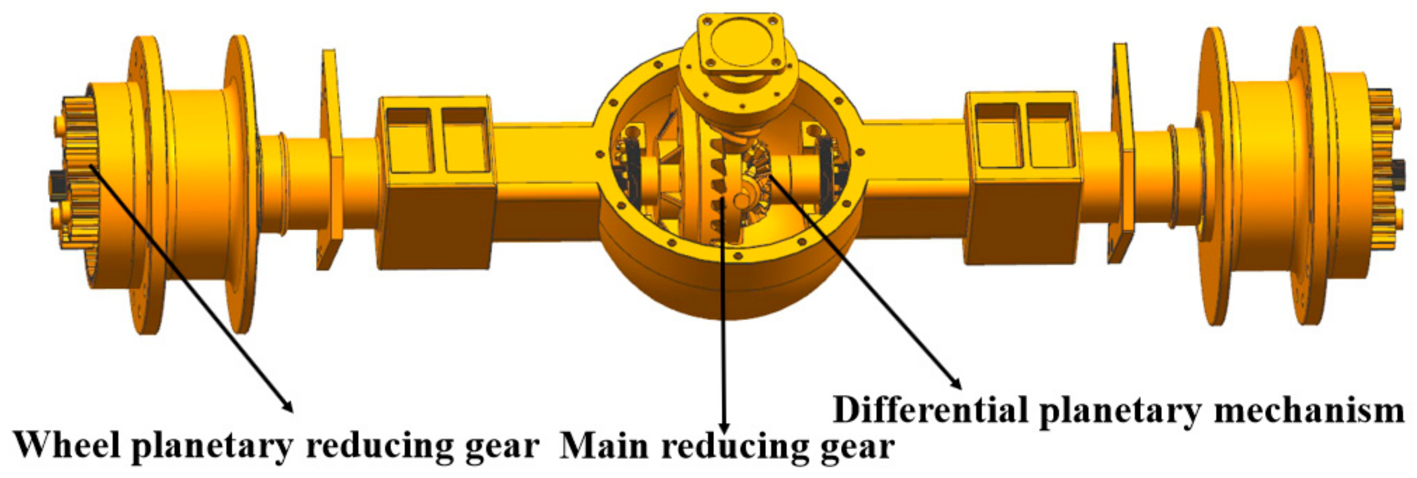
According to the geometric characteristics of the main reducing gear, the differential planetary mechanism, and the wheel planetary reducing gear of the loader drive axle, the 3D commercial software parametric design method was used to establish the three-dimensional (3D) model of the main reducing gear, the differential planetary mechanism, and the wheel planetary reducing gear of the loader drive axle, as seen in Figure 1. The loader drive axle assembly is shown in Figure 2, in which the numbers 0–8 represent the loader drive axle frame, the main reducing driving gear, the main reducing driven gear, the differential planetary mechanism planet gear, the half shaft gear, the wheel planetary reducing planet gear, and the carrier, respectively. The basic parameters of the loader drive axle are listed in Table 1.
2.2. Research on Transmission Efficiency of Loader Drive Axle
2.2.1. Research on Transmission Efficiency of the Main Reducing Gear
The theoretical transmission efficiency of the main reducing gear spiral bevel gear of the loader axle is shown in Equation (1) [16]:
where is the transmission efficiency; is driven gear load torque; is the driven gear peak torque at 2.75 times the fatigue limit bending stress; is the mesh friction coefficient; is the normal pressure angle of the driving gear surface; is the spiral bevel gear driving gear nominal helix angle; is the spiral bevel gear driven gear nominal helix angle; is the offset of the hypoid gear driving gear; and is the pitch diameter of the hypoid gear.
As reported by Saiki [17], the modified transmission efficiency of the spiral bevel gear does not depend on the load torque, as shown in Equation (2):
The nominal helix angle of the driving and driven spiral bevel gears is shown in Equations (3) and (4), respectively. F is the spiral bevel gear driven gear tooth width, and the rest of the symbol is in accordance with the meaning of Equation (1):
2.2.2. Research on Transmission Efficiency of the Differential Planetary Mechanism
The diagram of the differential planetary mechanism of the loader drive axle shown in Figure 2 can be converted into the diagram shown in Figure 3 without considering the gear mesh power loss. The rules for the graphical conversion process are detailed in [14]. The virtual split power ratio and the split power ratio of component 3 of the differential planetary mechanism of the loader drive axle are expressed by Equations (5) and (6), respectively:
where the virtual split power ratio of component 3 of the differential planetary mechanism of the loader drive axle is defined as the ratio between the virtual power passing to component 6 and the virtual power passing to component 4 (Figure 3b). and are the virtual power value flowing to member 6 and 4 and and are the power value flowing to member 6 and 4. ωi is the rotational angular velocity of component i. Specifically pointed out, the virtual power was measured by supposing that the observer stood on the carrier of a planetary gear train rotating at an angular velocity ωi. The speed ratio k was defined as the ratio of the rotational angular velocity of component 6 (ω6) to component 4 (ω4). It can be found from Equations (5) and (6) that , .
The virtual power ratio of component 4 of the differential planetary mechanism of the loader drive axle is defined as the ratio between the virtual power and the power passing through component 4 [9] (Figure 3a,b), and established the relationship between relative angular velocity and angular velocity, as shown in Equation (7).
where , ,
It can be obtained from Equation (7) that
The diagram of the differential planetary mechanism of the loader drive axle shown in Figure 2 can be converted into the diagram shown in Figure 4 when considering the gear mesh power loss. The gear mesh power loss is proportional to the input power, and the proportional ratio is called the mesh power loss coefficient, so , , and indicate the mesh power loss passing through the gear pairs , , and , respectively, which are expressed by Equations (9)–(11), respectively:
where represents the mesh power loss coefficient.
Considering the gear mesh power loss, the split power ratio of component 3 and the virtual power ratio of component 4 of the differential planetary mechanism of the loader drive axle are expressed by Equations (12) and (13), respectively (Figure 4a,b):
It can be obtained from Equations (12) and (13) that
From Equations (9)–(11), (14), and (15),
Accordingly, the transmission efficiency of the differential planetary mechanism of the loader drive axle is expressed as Equation (17):
2.2.3. Research on Transmission Efficiency of the Wheel Planetary Reducing Gear
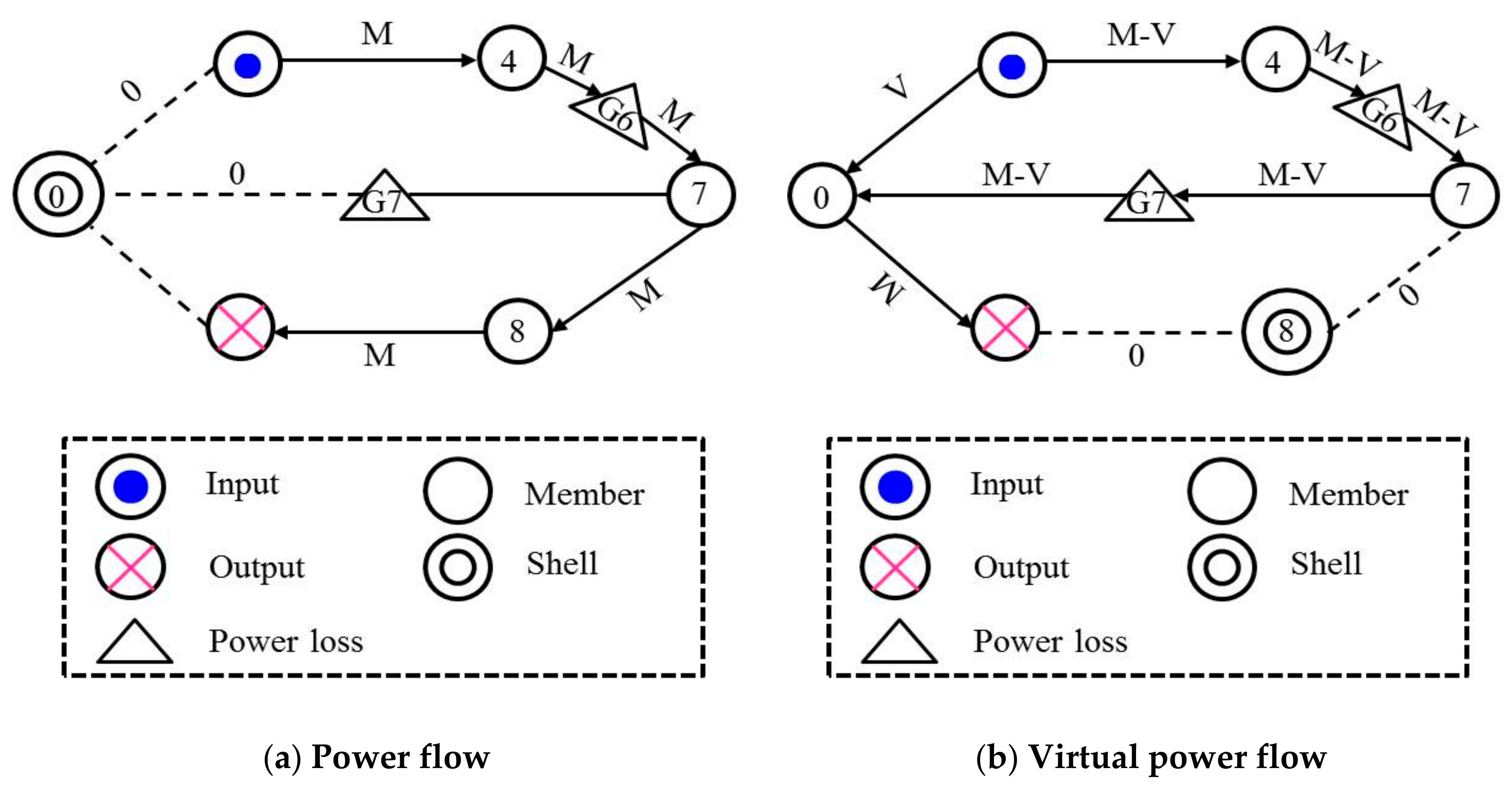
The diagram of the wheel planetary reducing gear of the loader drive axle shown in Figure 2 can be converted into the diagram shown in Figure 5 without considering the gear mesh power loss. The virtual power ratio of component 4 of the wheel planetary reducing gear of the loader drive axle is defined as the ratio between the virtual power and the power passing through component 4 [9], and expressed by Equation (18) (Figure 5a,b):
It can be obtained from Equation (18) that
The diagram of wheel planetary reducing gear of the loader drive axle shown in Figure 2 can be converted into the diagram shown in Figure 6 when considering the gear mesh power loss. and indicate the mesh power loss passing through the gear pairs and , respectively, which are expressed by Equations (20) and (21), respectively:
Considering the gear mesh power loss, the virtual power ratio of component 4 of the wheel planetary reducing gear of the loader drive axle is expressed by Equation (22) (Figure 6a,b):
From Equation (22),
Accordingly, the transmission efficiency of the wheel planetary reducing gear of the loader drive axle is expressed by Equation (24):
3. Results and Discussions
According to Equations (2), (17), and (24), the transmission efficiency of the main reducing gear, the differential planetary mechanism, and the wheel planetary reducing gear of the loader drive axle can be expressed by Equation (25):
To analyze the influence of the mesh friction coefficient μ of the main reducing gear on the transmission efficiency η of the loader drive axle, the curve of the transmission efficiency η of the loader drive axle and the mesh friction coefficient μ of the gear teeth were drawn under the condition that the other parameters shown in Equation (25) were unchanged (Figure 7). According to Figure 7, the transmission efficiency η of the loader drive axle decreased when the mesh friction coefficient μ of the main reducing gear increased under the condition that the other parameters were unchanged. Simultaneously, the mesh friction coefficient μ of the main reducing gear was 0.05, and the transmission efficiency η of the loader drive axle was 0.707.
To determine if the transmission efficiency η of the loader drive axle is affected by the mesh power loss coefficient λi, the curve of the transmission efficiency η of the loader drive axle and the mesh power loss coefficient λi was drawn under the condition that the other parameters shown in Equation (25) were unchanged (Figure 8). According to Figure 8, the transmission efficiency η of the loader drive axle decreased as the mesh power loss coefficient λi increased. That is, the transmission efficiency η of the loader drive axle decreased as the mesh power loss coefficients λ1 and λ6 increased, and it also decreased as the mesh power loss coefficients λ3 and λ7 increased. As the mesh power loss coefficients λ3 and λ7 increased, the transmission efficiency η of the loader drive axle decreased, but the degree of decrease was slower than λ1 and λ6; as the mesh power loss coefficient λ2 increased, it initially decreased slowly and then sharply.
Here, the speed ratio γ was defined as the ratio of the rotational angular velocity of component 2 (ω2) to component 4 (ω4), as shown in Equation (26):
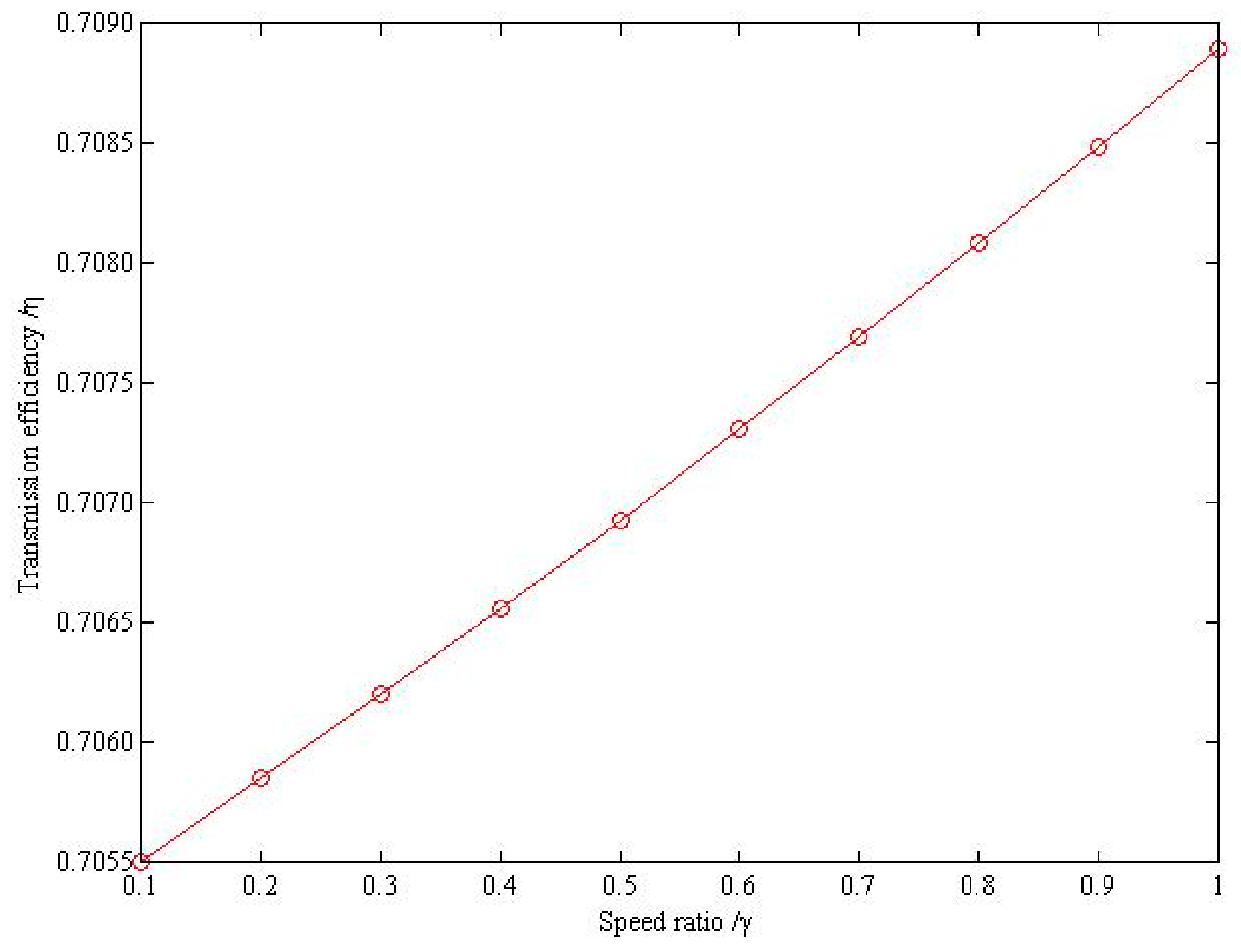
To determine if the transmission efficiency η of the loader drive axle is affected by the speed ratio γ, the curve of the transmission efficiency η of the loader drive axle and the speed ratio γ were drawn under the condition that the other parameters shown in Equation (25) were unchanged (Figure 9). According to Figure 9, the transmission efficiency η of the loader drive axle increased with the increase of the speed ratio γ when the other parameters were unchanged, but the transmission efficiency η ranged from 0.7055 to 0.7090; that is, the modification of the speed ratio γ had no obvious effect on the transmission efficiency η of the loader drive axle.
4. Conclusions
- (1)
- By establishing a three-dimensional digital model of a loader drive axle, the transmission efficiency of the main reducing gear, the differential planetary mechanism, and the wheel planetary reducing gear of the loader drive axle are studied. The transmission efficiency functional relationship between the loader drive axle and the main reducing gear, differential planetary mechanism, and wheel planetary reducing gear were obtained; that is, a functional relationship between the transmission efficiency of the loader drive axle and the gear mesh friction coefficient, the mesh power loss coefficient, the normal pressure angle, the helix angle, the offset amount, the speed ratio, and the characteristic parameters.
- (2)
- The transmission efficiency of the loader drive axle increased with speed ratio and decreased when the gear teeth mesh friction coefficient and the mesh power loss coefficient increased. However, compared with the mesh power loss coefficient, the degree of influence of the transmission efficiency of the loader drive axle was different than the gear teeth friction coefficient, and the mesh power loss coefficient of each gear pair had a different influence on the transmission efficiency of the loader drive axle.
Based on the above research of this paper, the influence of rolling element bearings and temperatures of the gears on the transmission efficiency of the loader drive axle was carried out, so that the influence of multiple factors on the transmission efficiency of the loader drive axle can be studied more comprehensively.
Author Contributions
J.L. performed the formula derivation, data analyses, and wrote the manuscript; T.M. and Q.H. proposed the concept of the study; T.W. and W.C. contributed to writing, reviewing, and editing.
Funding
This research was funded by the Research Project of Guangdong Higher Education Institute (19GYB014), the Zhaoqing University Quality Engineering and Teaching Reform Project (zlgc201751 and zlgc201829), and the Guangdong Youth Innovation Talents Project (2018KQNCX290).
Acknowledgments
The authors wish to express their gratitude to the School of Mechanical and Automotive Engineering, Zhaoqing University, and express their gratitude for the funding provided by the Guangdong Youth Innovation Talents Project.
Conflicts of Interest
The authors declare no conflicts of interest.
References
- Xu, H.; Kahraman, A. Prediction of friction-related power losses of hypoid gear pairs. Proc. Inst. Mech. Eng. Part K J. Multi-Body Dyn. 2007, 221, 387–400. [Google Scholar] [CrossRef]
- Fanghella, P.; Bruzzone, L.; Ellero, S.; Landò, R. Kinematics, Efficiency and Dynamic Balancing of a Planetary Gear Train Based on Nutating Bevel Gears. Mech. Based Des. Struct. Mach. 2015, 44, 72–85. [Google Scholar] [CrossRef]
- Kakavasa, I.; Olvera, A.V.; Dinia, D. Hypoid Gear Vehicle Axle Efficiency. Tribol. Int. 2016, 101, 314–323. [Google Scholar] [CrossRef]
- Paouris, L.; Theodossiades, S.; Rahmani, R.; Rahnejat, H.; Hunt, G.; Barton, W. Effect of Lubricant Rheology on Hypoid Gear Pair Efficiency. In Proceedings of the 3rd Biennial International Conference on Powertrain Modelling and Control, Loughborough, UK, 7–9 September 2016; pp. 1–25. [Google Scholar]
- Simon, V. Improvements in the Mixed Elastohydrodynamic Lubrication and in the Efficiency of Hypoid Gears. Proc. Inst. Mech. Eng. Part J J. Eng. Tribol. 2019. [Google Scholar] [CrossRef]
- Lyu, C.; Zhao, Y.; Lyu, M. Loader Power-Split Transmission System Based on a Planetary Gear Set. Adv. Mech. Eng. 2018, 10, 1–8. [Google Scholar] [CrossRef]
- Xiong, S.; Wilfong, G.; Lumkes Jr., J. Components Sizing and Performance Analysis of Hydro-Mechanical Power Split Transmission Applied to a Wheel Loader. Energies 2019, 12, 1613. [Google Scholar] [CrossRef]
- Bardav, D.; Fossier, C.; Changenet, C.; Ville, F.; Berier, V. Investigations on Drive Axle Thermal Behaviour: Power Loss and Heat-Transfer Estimations. SAE Int. J. Eng. 2018, 11, 55–66. [Google Scholar]
- Chen, C.; Angeles, J. Virtual power flow and mechanical gear-mesh power losses of epicyclic gear trains. J. Mech. Des. 2007, 129, 107–113. [Google Scholar] [CrossRef]
- Chen, C.; Liang, T.T. Theoretic study of efficiency of two DOFs of epicyclic gear transmission via virtual power. J. Mech. Des. 2011, 133, 031007–031013. [Google Scholar] [CrossRef]
- Chen, C. Power flow analysis of compound epicyclic gear transmission: Simpson gear train. J. Mech. Des. 2011, 133, 1–5. [Google Scholar] [CrossRef]
- Chen, C. Power Analysis of Epicyclic Transmissions Based on Constraints. J. Mech. Robot. 2012, 4, 041004. [Google Scholar] [CrossRef]
- Chen, C. Power flow and efficiency analysis of epicyclic gear transmission with split power. Mech. Mach. Theory 2013, 59, 96–106. [Google Scholar] [CrossRef]
- Hu, Q.C.; Li, J.Y.; Duan, F.H. Power Flow and Efficiency Analysis of Compound Planetary Gears Transmission with Bevel Gears. J. Mech. Eng. 2015, 51, 42–48. [Google Scholar] [CrossRef]
- Li, J.Y.; Wu, T.L.; Zhu, T.J.; Hu, Q.C.; Cai, C.M.; Zong, C.F. Influence of Multi-Factor on the Transmission Efficiency of Multistage Micro-Planetary Gearing Transmission. Microsyst. Technol. 2019. [Google Scholar] [CrossRef]
- Beijing Gear Factory. Gleason Technical Information Translation, 2nd ed.; Mechanical Industry Press: Beijing, China, 1983; pp. 137–139. [Google Scholar]
- Saiki, K.; Fukamachi, S. Research on High Efficiency Hypoid Gear for Automotive Application. In Proceedings of the 14th IFToMM World Congress, Taipei, Taiwan, 25–30 October 2015; pp. 293–297. [Google Scholar]
Figure 1.
Three-dimensional (3D) digital model of the loader drive axle.

Figure 2.
Schematic diagram of the loader drive axle.

Figure 3.
Power flows of differential planetary mechanism without considering the gear mesh power loss.
Figure 3.
Power flows of differential planetary mechanism without considering the gear mesh power loss.

Figure 4.
Power flows of differential planetary mechanism considering the gear mesh power loss.

Figure 5.
Power flows of wheel planetary reducing gear without considering the gear mesh power loss.
Figure 5.
Power flows of wheel planetary reducing gear without considering the gear mesh power loss.

Figure 6.
Power flows of wheel planetary reducing gear considering the gear mesh power loss.

Figure 7.
Relationship of the transmission efficiency η of the loader drive axle and the mesh friction coefficient μ.
Figure 7.
Relationship of the transmission efficiency η of the loader drive axle and the mesh friction coefficient μ.
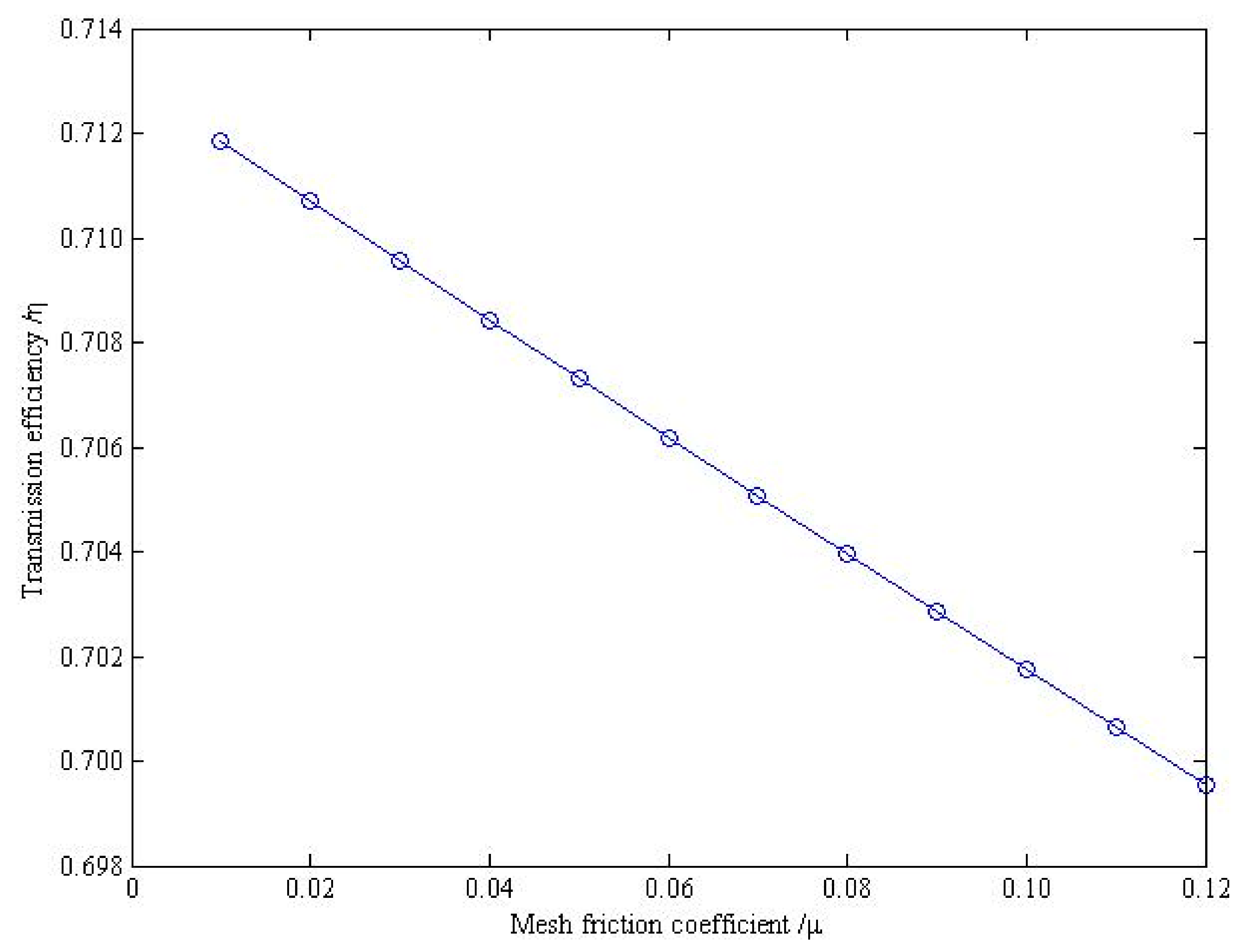
Figure 8.
Relationship of the transmission efficiency η of the loader drive axle and the mesh power loss coefficient λi.
Figure 8.
Relationship of the transmission efficiency η of the loader drive axle and the mesh power loss coefficient λi.
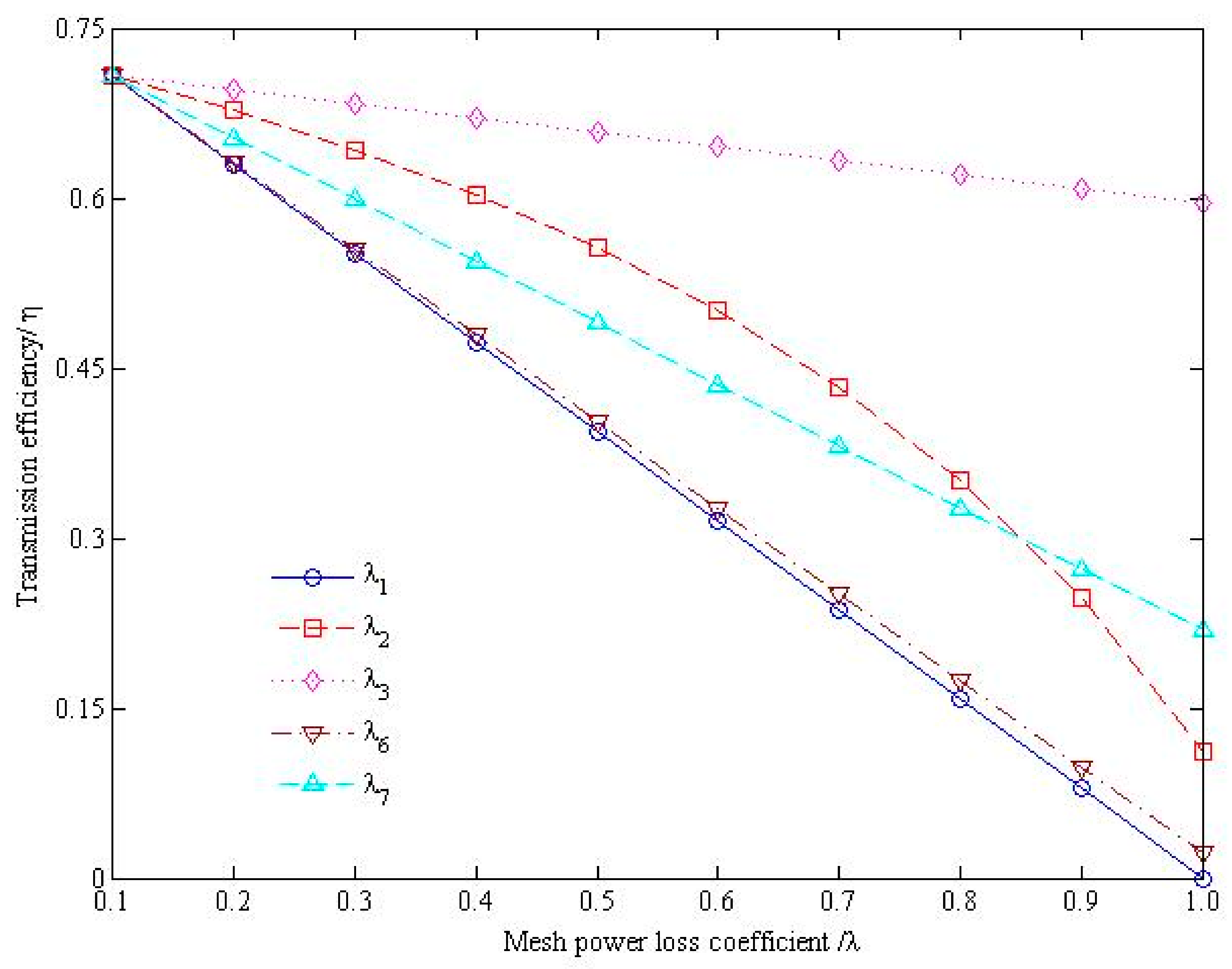
Figure 9.
Relationship of the transmission efficiency η of the loader drive axle and the speed ratio γ.
Figure 9.
Relationship of the transmission efficiency η of the loader drive axle and the speed ratio γ.


Table 1.
Basic parameters of the loader drive axle.
| Main Reducing Gear | ||
|---|---|---|
| Name | Driving Gear | Driven Gear |
| Number of teeth | 7 | 37 |
| Transverse module (mm) | 10.7 | |
| Normal pressure angle | 20° 30′ | |
| Differential Planetary Mechanism | ||
| Name | Planet Gear | Half Shaft Gear |
| Number of teeth | 10 | 18 |
| Large transverse module (mm) | 7 | |
| Pressure angle | 25° | |
| Wheel Planetary Reducing Gear | ||
| Name | Sun Gear | Planet Gear |
| Number of teeth | 17 | 15 |
| Modulus (mm) | 5.5 | |
| Pressure angle | 20° | |
© 2019 by the authors. Licensee MDPI, Basel, Switzerland. This article is an open access article distributed under the terms and conditions of the Creative Commons Attribution (CC BY) license (http://creativecommons.org/licenses/by/4.0/).
Share and Cite
MDPI and ACS Style
Li, J.; Wu, T.; Chi, W.; Hu, Q.; Meen, T. Integrated Analysis of Influence of Multiple Factors on Transmission Efficiency of Loader Drive Axle. Energies 2019, 12, 4540. https://doi.org/10.3390/en12234540
AMA Style
Li J, Wu T, Chi W, Hu Q, Meen T. Integrated Analysis of Influence of Multiple Factors on Transmission Efficiency of Loader Drive Axle. Energies. 2019; 12(23):4540. https://doi.org/10.3390/en12234540
Chicago/Turabian StyleLi, Jianying, Tunglung Wu, Weimin Chi, Qingchun Hu, and Teenhang Meen. 2019. "Integrated Analysis of Influence of Multiple Factors on Transmission Efficiency of Loader Drive Axle" Energies 12, no. 23: 4540. https://doi.org/10.3390/en12234540
Note that from the first issue of 2016, this journal uses article numbers instead of page numbers. See further details here.