Reduction of Heat Losses Using Quadruple Heating Pre-Insulated Networks: A Case Study


1
Department of HVAC Engineering, Bialystok University of Technology, 15-351 Bialystok, Poland
2
School of Engineering Sciences of Belmez, University of Cordoba, 14240 Cordoba, Spain
*
Author to whom correspondence should be addressed.
Energies 2019, 12(24), 4699; https://doi.org/10.3390/en12244699
Submission received: 25 October 2019
/
Revised: 5 December 2019
/
Accepted: 6 December 2019
/
Published: 10 December 2019
(This article belongs to the Special Issue Innovations-Sustainability-Modernity-Openness in Energy Research 2019)
Abstract
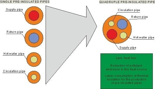
:The paper presents an analysis of heat loss and reductions of annual emissions of air pollutants of a quadruple pre-insulated heating network by comparing this solution with the existing pre-insulated network consisting of four pre-insulated single pipes and the variant consisting of two twin pipe pre-insulated. For calculations, an existing heating network located in central Poland was adopted, where heat is transported for heating purposes of buildings and domestic hot water with circulation of domestic hot water through four separate pre-insulated underground pipes. The idea of the construction of four pre-insulated pipes presented in the paper consists in the location of four steel pipes in a common round thermal insulation, which perform the role of heat transport for heating purposes in multi-family buildings (supply and return) and two pipes transporting hot water (a pipe with domestic hot water with circulation). In Poland, heating pipes used in multi-family housing have a larger diameter compared to domestic hot water pipes, which is why standard twin pipe heating pipes have been used in the construction of four pre-insulated networks, in which the domestic hot water pipe has been added to the thermal insulation and circulation of domestic hot water. In order to determine heat losses, a simplified two-dimensional model of conductive heat transfer was developed using Fortran to create a computer program. The results of numerical simulations show that the use of twin pipes for the construction of pre-insulated quadruple networks has contributed to a significant reduction in heat loss in relation to the existing single pre-insulated network (up to 57.1%), while reducing the thermal insulation field of the cross-section of the pre-insulated pipe by 21.4%.
1. Introduction
Energy-efficient operation of heating networks is primarily associated with the reduction of heat losses in pre-insulated pipes. The simplest method of reducing heat loss is to reduce the network operating temperature [1,2,3,4,5]. Unfortunately, the reduction of network operation parameters is associated with costly thermal modernization of the building, i.e., insulation of buildings and replacement of the heating system [6]. Reduction of heat loss in heating networks can also be achieved by using thicker layers of thermal insulation or heating networks with a lower thermal conduction coefficient of thermal insulation, which is associated with a higher cost of heating networks. Heat exchange in single pre-insulated heating networks, which are the most commonly used, has been thoroughly studied [7,8,9,10,11]. Heat losses in single pre-insulated pipes can be determined using analytical methods [3,7,9,12,13] as well as using numerical methods in two-dimensional [10,12] and three-dimensional [14] problems. Another method of reducing heat loss is to place a few pipes in common thermal insulation. This method is mainly used in twin pipes, where the supply and return pipes are located in circular insulation [15,16]. One of the methods to reduce heat loss in pre-insulated twin pipes is to change the cross-sectional shape of the twin pipe thermal insulation from round to oval [17], elliptical [18] or egg shape [19,20] while maintaining the same cross-sectional area of thermal insulation. Heat losses in pre-insulated twin pipes can be determined by simplified analytical methods [12,21,22] and numerical methods [16,17,18,19,23]. Heat losses in pre-insulated double pipes with round thermal insulation are about 30% lower than heat losses in pre-insulated single pipes [19,20,22]. It should be noted here that the improvement of thermal insulation also depends on the size of the pipes. In the case of double pre-insulated heating pipes with an egg-shaped cross-section, heat losses are smaller by about 45% compared to heat losses in single pre-insulated pipes [19,20]. The pre-insulated triple pipes are also described in the literature [15,19] in which heat is transported by means of two supply pipes and one return pipe.
Another alternative is pre-insulated quadruple pipes, where all four pipes are encased in common round thermal insulation. Pre-insulated quadruple ducts can be used for heat transport during the heating season and for the transport of domestic hot water along with the circulation of domestic hot water. While single pre-insulated and twin pipes have been thoroughly investigated [1,2,3,4,5,6,7,8,9,10,11,12,13,14,15,16,17,18,19,20,21,22], the heat loss analysis of four-pre-insulated pipes has not yet been performed.
The purpose of the work is to analyze heat loss and the ecological effect of pre-insulated quadruple pipes by comparing this solution with the existing pre-insulated network built of four single pre-insulated pipes and an additional adopted variant of the network consisting of two twin pipes. The reduction of heat loss is associated with lower emissions of pollutants into the air from heat sources if the heat source is fossil fuel, i.e., it significantly affects the ecological effect of heating networks operation [24,25]. The paper adopts the geometry of pre-insulated quadruple pipes by placing additional pipes for domestic hot water and circulation of domestic hot water in the thermal insulation of a standard twin pipe designed for heat transport for the purposes of heat demand of buildings.
2. Description of the Model for Determining Heat Loss in Pre-Insulated Quadruple Pipes
In order to determine heat losses through pre-insulated pipes, a computer program was created using the Fortran language using the boundary element method (BEM) [26], which is often used in many heat transfer analysis [27,28,29]. The boundary element method is a non-mesh method and for given boundary conditions in the form of temperature or heat flux, it allows the determination of heat fluxes for individual pipes inside thermal insulation. It should be noted that in the case of single heating networks and twin pipes, analytical formulas may be used to determine heat losses, the results of which are consistent with the results of numerical methods [12], while in the case of pre-insulated quadruple heating pipes in common thermal insulation, analytical formulas are not known. A two-dimensional simplified model of heat conduction described in Laplace’s equation and the Fourier equations were used for calculations:
where T is the temperature, x and y are the coordinates of the Cartesian system in the cross section of the pre-insulated pipe, qx and qy are heat-flow quantities that are directed in the x and y directions, while λ is the thermal conductivity coefficient of the thermal insulation (polyurethane foam).
Figure 1 presents the boundary conditions of heat transfer using a simplified model of heat exchange inside a quadruple pre-insulated pipe. The Dirichlet boundary condition in the form of the external surface temperature of the thermal insulation TG = 8 °C and the temperature of the walls of steel pipes equal to the temperature of the heating medium flowing on the TS supply and return TR as well as domestic hot water TH together with the circulation of domestic hot water TC was adopted for calculations. The thermal conductivity coefficient of thermally insulating materials depends on temperatures, material age and density. Standard thermal insulation made of polyurethane foam with an average thermal conductivity coefficient of λ = 0.0265 W/mK was used in the calculations. Parameters of thermal insulation made of polyurethane foam can be found in [30,31]. The unit heat losses q through the quadruple pre-insulated pipe consist of heat losses through the heating supply pipe and return and heat losses through the domestic hot water pipe and domestic hot water circulation :
where heat losses for individual pipes are described by the heat flux balance according to Figure 1:
The solution of Equation (1) for given boundary conditions is the heat flux density at the boundary of thermal insulation. To determine heat loss by the boundary element method, no mesh inside the thermal insulation cross-section is required, only the boundary of the thermal insulation is discretized. After determining the heat flux density at the boundary of thermal insulation by the boundary element method, the temperature or density of the heat flux at any point within the cross-section of thermal insulation is also determined without the use of meshes. The computer program verification was carried out in the works [18,32]. A boundary of 5000 linear elements was used for calculations.
3. Analysis of Heat Losses of Pre-Insulated Quadruple Networks on the Basis of Operating Parameters of the Existing Pre-Insulated Single Network and the Adopted Twin Pipe Network
The analysis of quadruple pre-insulated network heat loss in a common thermal insulation was made on the basis of the operating parameters of the existing single pre-insulated network investment made in 2012, supplying heat from the local coal-fired heating plant during the heating season and domestic hot water for multi-family and service buildings located in central Poland. A satellite view of the housing estate of multi-family buildings connected to the heating network is shown in Figure 2a [33], while a diagram of the existing pre-insulated network with the diameters of single pre-insulated pipes is shown in Figure 2b.
In order to analyze the energy losses for the purposes of heat loss and the ecological effect of the quadruple pre-insulated heating network, three variants of the pre-insulated network design were used for heating in the heating season and transporting hot water (Figure 3). The first variant marked as “I” is the existing state of a single pre-insulated network built of four pipes: the supply and return pipes of the heating system marked as S and R respectively (Figure 3a) and the pipe supplying domestic hot water to buildings and circulation of domestic hot water marked respectively as H and C (Figure 3a). Pre-insulated heating network pipes S and R with a flow temperature TS =80 °C and return temperature TR = 60 °C work only during the heating season for a period of 255 days, while hot utility water pipes with a temperature TH = 55 °C and TC = 55 °C work all year round. The temperature of pre-insulated heating network, domestic hot water and circulation of domestic hot water is kept constant. The heating medium is transported through a pre-insulated network to local heating centers located in buildings, where behind the heat exchangers inside buildings the temperature of the heating medium is regulated depending on the outside temperature. Linear heat density for the analysed network was estimated at 3.3 MWh/(m year). Fluid flow was in a range from 1.58 t/h to 21.5 t/h in heating pipes and between 0.2 t/h and 0.45 t/h in hot water and circulation pipes. Loss of pressure for the design flow was 27.5 kPa and 5.0 kPa, respectively. The detailed geometry with the description of the pipe diameters and thermal insulation fields as well as the unit heat losses determined for the supply and return pipes of the existing heating network, respectively as qIa, qIb and the unit heat losses for existing domestic hot water pipes and domestic hot water circulation marked as qIc and qId, respectively, are presented in Table 1. The description of the geometric parameters from Table 1 is in Figure 3a.
In the second variant (Figure 3b, Table 2) a heating network was adopted consisting of two twin pipe ducts working for heating purposes and domestic hot water on the same thermal parameters as in variant “I”. The dimensions of the diameters of steel heating and domestic hot water were taken equal to the dimensions of the pipes in variant “I” and the standard diameters of thermal insulation were adopted. The geometry of the twin pipe ducts assumed for calculations (Figure 3b) and the determined unit heat losses of pre-insulated heating and domestic hot water pipes, qIIa and qIIb, respectively, are presented in Table 2.
The third variant (III) is a quadruple pre-insulated network, where two heat pipes and two domestic hot water pipes are located in one thermal insulation (Figure 3c, Table 3). Pre-insulated quadruple ducts have been designed using the assumed “II” heating ducts for twin pipe heating purposes. Figure 4a–d show an example of temperature and density distribution in a twin pipe, assuming D4 = 250 mm and d1 = 88.9 mm. Based on significant values of heat flux density (Figure 4b), local areas of significant intensification of heat exchange between the pipe and the environment and areas with low heat transfer, which are characterized by a low heat flux density, can be identified. Additional domestic hot water and domestic hot water circulation pipes can be placed in the area of thermal insulation where the heat flux density is low. The smallest heat flux density values are located on the left and right of the supply and return pipes (Figure 4b) and additional hot water pipes have been located here. It should be pointed out here that the pipes transporting domestic hot water used in Poland have smaller diameters than district heating pipes. The result of adding domestic hot water pipes and domestic hot water circulation is a reduction in the cross-sectional area of thermal insulation in pre-insulated quadruple pipes by about 40% compared to two twin pipes from variant II (Table 1, Table 3).
In quadruple pre-insulated pipes, an increase in the temperature gradient was observed (Figure 4c) as well as an increase in heat flux density (Figure 4d) inside the thermal insulation compared to twin pipes, however, the total heat loss of the quadruple pre-insulated network compared to two double-pre-insulated pipes are smaller. In order to reduce the heat exchange between four pipes in common thermal insulation, the minimum distances between these pipes s1 (Table 3) have been adopted equal to the distances s1 between pipes in twin pipe pre-insulated pipes (Table 4). The impact of distance between heating pipes on heat losses of pre-insulated pipes has been described in papers [15,18,19]. By analysing heat exchange in pre-insulated pipes, it is also possible to reduce heat losses by modifying the shape of thermal insulation, which was also done in works for twin pipe pre-insulated pipes [17,20].
In order to analyze the thermal insulation of the quadruple heating pre-insulated network, energy for heat losses was determined for the existing condition of the pre-insulated network and for two assumed variants. Energy for heat losses on individual sections of pre-insulated pipes was determined in accordance with the following relationship:
where j is the pipe number according to Figure 2b and Table 1, Table 2 and Table 3, Li is the length of the pipe according to Figure 2b, t is time, qji is the unit heat loss depending on the adopted variant, N- total number of pipes, which is described by the relationships in Table 4 and the unit heat loss values from Table 1, Table 2 and Table 3, while the lower index i is the type of variant (i = I, II, III).
Table 5 shows energy consumption for heat losses for three heating network variants (I, II, III) detailing the heating season (255 days), non-heating season (110 days), when the network only transports domestic hot water with circulation and annual energy consumption for heat losses (365 days).
Figure 5a presents the percentage comparison of the cross-sectional area of thermal insulation of selected pre-insulated pipes, while Figure 5b presents the percentage comparison of the annual energy consumption for heat losses of selected pipes, assuming that the existing condition (variant I) is equal to 100% both in the case of surface area thermal insulation and energy consumption for heat losses.
Annual energy consumption for heat losses in quadruple networks (variant III) is about 57.1% and 12.6% (Table 5) lower than for four single pre-insulated networks (variant I) and two double pre-insulated networks (variant II) respectively. It should be noted here that the average surface area of thermal insulation in adopted quadruple pre-insulated heating networks is lower by 21.4% and 40.2%, respectively, than four single pre-insulated networks and two double pre-insulated networks.
The main assumption of this work was the use of pre-insulated double thermal insulation for the construction of quadruple pipes by adding two domestic hot water pipes to twin pipe heating pipes in common thermal insulation, therefore it was not decided to increase the surface area of thermal insulation in quadruple pipes. In the case of increasing the surface area of thermal insulation of quadruple pipes (variant III) to the value of the field of thermal insulation of double pre-insulated pipes (variant II), the heat loss of the quadruple pipe in relation to two double pipes would be much smaller. The largest area of thermal insulation in the cross-section of pre-insulated pipe has two double pre-insulated networks in which the insulation area is 31.1% larger (Figure 5a) than the insulation field for four single pre-insulated networks (variant I), resulting in annual energy (Figure 5b) for heat losses of two twin pipe pre-insulated pipes (variant II) is about 51% smaller than in variant I.
Analysing the unit heat losses in the heating season without taking into account the domestic hot water, it can be seen that in the case of twin pipes the unit heat losses (Table 2) are smaller by about 34.8% than single pre-insulated networks (Table 1). Similar results were obtained in [19,20,22] (Figure 6), where the differences between the results did not exceed 5%. After taking into account the heat losses in domestic hot water pipes and circulation of domestic hot water, the unit heat losses in twin pipes are lower by as much as 50% from the unit heat losses of single pre-insulated pipes. Such a significant difference in unit heat losses between twin pipes and single pipes, including hot water pipes, results from the fact that hot water pipes and hot water circulation pipes are characterized by small diameters, which are much better thermally insulated than single pre-insulated pipes for these small diameters.
In the period outside the heating season, when the network only transports domestic hot water (Table 5), energy for heat losses in pre-insulated quadruple pipes is slightly higher than in the case of two double pre-insulated pipes, which is caused by a smaller thickness of thermal insulation in pre-insulated quadruples relative to twin pipe hot water.
Based on the determined annual energy for heat losses and emissivity coefficients [34,35], the ecological effect of using pre-insulated quadruple pipes for the following pollutants emitted into the atmosphere was determined: nitrogen oxides (NOX), carbon monoxide (CO), non-methane volatile organic compounds (NMVOC), sulfur oxides (SOX), total suspended particles (TSP), particulate matter (PM10 and PM2.5), carbon dioxide (CO2) and methane (CH4). Reductions of annual emissions of air pollutants for all variants were determined using the known formula [34]:
where: EI is the annual energy for heat losses in the existing variant of type I, (single four-pipe network), while Ei (i = II or i = III) is the annual energy for heat losses in variants II and III. Annual energy for the purposes of heat losses EI, EII and EIII are determined from formula 6.
ΔEI-i = (EI − Ei) × Ef
As showed in Table 6, the average annual emission of pollutants for variant III (quadruple pre-insulated network) is lower by approximately 57% and 13% compared to the condition of the existing variant I (single pre-insulated network) and two twin pipe ducts (variant II), respectively. It should be noted here that pollutants emitted to the atmosphere as a result of fuel combustion depend on the composition of the fuel and the method of combustion.
4. Conclusions
Standard thermal insulation in twin pipe ducts used for heat transport allows the placement of two additional smaller diameter pipes compared to heating pipes. Such pipes can be domestic hot water pipes and domestic hot water circulation pipe, which together with the heating pipes form a pre-insulated quadruple pipe. Quadruple pre-insulated pipes significantly reduce heat loss and increase the ecological effect compared to four single pre-insulated pipes while reducing the cross-sectional area of the thermal insulation. An additional advantage is the smaller trench in the ground for a pre-insulated quadruple pipes compared to four single or two pre-insulated double pipes. The presented solution of pre-insulated quadruple pipes can also be an alternative to two twin pipes, where one pre-insulated double pipe is transported heat, while the other twin pipe is used for domestic hot water along with the circulation of domestic hot water. Comparing the pre-insulated quadruple pipes with two twin pipes, also smaller heat losses and smaller thermal insulation field in the cross-section of the pipes were obtained.
Author Contributions
D.A.K. and T.J.T. proposed the research methodology and aims, as well as organized the draft of the manuscript; T.J.T. conducted simulations and prepared figures, D.A.K., T.J.T. and A.R. analyzed the simulation results, wrote the manuscript and agreed to submission.
Funding
This research was funded by NAWA, BUT InterAcademic Partnerships (PPI/APM/2018/1/00033/DEC/1) and WZ/WBiIS/9/2019 scientific research at Bialystok University of Technology.
Conflicts of Interest
The authors declare no conflict of interest.
References
- Pirouti, M.; Bagdanavicius, A.; Ekanayake, J.; Wu, J.; Jenkins, N. Energy consumption and economic analyses of a district heating network. Energy 2013, 57, 149–159. [Google Scholar] [CrossRef]
- Neirotti, F.; Noussan, M.; Riverso, S.; Manganini, G. Analysis of different strategies for lowering the operation temperature in existing district heating networks. Energies 2019, 12, 321. [Google Scholar] [CrossRef] [Green Version]
- Yang, W.; Wen, F.; Wang, K.; Huang, Y.; Salam, M.A. Modeling of a district heating system and optimal heat-power flow. Energies 2018, 11, 929. [Google Scholar] [CrossRef] [Green Version]
- Dalla Rosa, A.; Li, H.; Svendsen, S. Method for optimal design of pipes for low-energy district heating with focus on heat losses. Energy 2011, 36, 2407–2418. [Google Scholar] [CrossRef]
- Boysen, C.; Kaldemeyer, C.; Hilpert, S.; Tuschy, I. Integration of flow temperatures in unit commitment models of future district heating systems. Energies 2019, 12, 1061. [Google Scholar] [CrossRef] [Green Version]
- Krawczyk, D.A. Theoretical and real effect of the school’s thermal modernization—A case study. Energy Build. 2014, 81, 30–37. [Google Scholar] [CrossRef]
- Song, S.H.; Cheing, T. Pattern-based set partitioning algorithm for the integrated sustainable operation of a district heating network. Sustainability 2018, 10, 2774. [Google Scholar] [CrossRef] [Green Version]
- Kontu, K.; Vimpari, J.; Penttinen, P.; Junnila, S. City scale demand side management in three different-sized district heating systems. Energies 2018, 11, 3370. [Google Scholar] [CrossRef] [Green Version]
- Kudela, L.; Chylek, R.; Pospisil, J. Performant and simple numerical modeling of district heating pipes with heat accumulation. Energies 2019, 12, 633. [Google Scholar] [CrossRef] [Green Version]
- Zhao, J.; Shan, Y. An influencing parameters analysis of district heating network time delays based on the CFD method. Energies 2019, 12, 1297. [Google Scholar] [CrossRef] [Green Version]
- Salo, S.; Hast, A.; Jokisalo, J.; Kosonen, R.; Syri, S.; Hirvonen, J.; Martin, K. The impact of optimal demand response control and thermal energy storage on a district heating system. Energies 2019, 12, 1678. [Google Scholar] [CrossRef] [Green Version]
- Oclon, P.; Nowak-Oclon, M.; Vallati, A.; Quintino, A.; Corcione, M. Numerical determination of temperature distribution in heating network. Energy 2019, 183, 880–891. [Google Scholar] [CrossRef]
- Sun, G.; Wang, W.; Wu, Y.; Hu, W.; Yang, Z.; Wei, Z.; Zang, H.; Chen, S. A nonlinear analytical algorithm for predicting the probabilistic mass flow of a radial district heating network. Energies 2019, 12, 1215. [Google Scholar] [CrossRef] [Green Version]
- Danielewicz, J.; Śniechowska, B.; Sayegh, M.A.; Fidorów, N.; Jouhara, H. Three-dimensional numerical model of heat losses from district heating network pre-insulated pipes buried in the ground. Energy 2016, 108, 172–184. [Google Scholar] [CrossRef] [Green Version]
- Bøhm, B.; Kristjansson, H. Single, twin and triple buried heating pipes: On potential savings in heat losses and costs. Int. J. Energy Res. 2005, 29, 1301–1312. [Google Scholar] [CrossRef]
- Khosravi, M.; Arabkoohsar, A. Thermal-hydraulic performance analysis of twin-pipes for various future district heating schemes. Energies 2019, 12, 1299. [Google Scholar] [CrossRef] [Green Version]
- Teleszewski, T.J.; Zukowski, M. Modification of the shape of thermal insulation of a twin-pipe pre-insulated network. AIP Conf. Proc. 2019, 2078, 020030. [Google Scholar]
- Krawczyk, D.A.; Teleszewski, T.J. Optimization of geometric parameters of thermal insulation of pre-insulated double pipes. Energies 2019, 12, 1012. [Google Scholar] [CrossRef] [Green Version]
- Kristjansson, H.; Bøhm, B. Advanced and Traditional Pipe Systems Optimum Design of Distribution and Service Pipes; Technical Paper; Euroheat and Power: Brussels, Belgium, 2006; pp. 34–42. [Google Scholar]
- Krawczyk, D.A.; Teleszewski, T.J. Reduction of heat losses in a pre-insulated network located in central Poland by lowering the operating temperature of the water and the use of egg-shaped thermal insulation: A case study. Energies 2019, 12, 2104. [Google Scholar] [CrossRef] [Green Version]
- Van der Heijde, B.; Aertgeerts, A.; Helsen, L. Modelling steady-state thermal behaviour of double thermal network pipes. Int. J. Therm. Sci. 2017, 117, 316–327. [Google Scholar] [CrossRef] [Green Version]
- Babiarz, B.; Zięba, B. Heat losses in the preinsulated district heating systems. Civ. Environ. Eng. 2012, 283, 5–19. [Google Scholar]
- Bennet, J.; Claesson, J.; Hellström, G. Multipole method to compute the conductive heat flows to and between pipes in a composite cylinder. LUTVDGf (TVBH-7094)/1-42/(1987). Notes Heat Transfer 1987, 3, 1–44. [Google Scholar]
- Ravina, M.; Panepinto, D.; Zanetti, M.C.; Genon, G. Environmental analysis of a potential district heating network powered by a large-scale cogeneration plant. Environ. Sci. Pollut. Res. 2017, 24, 13424–13436. [Google Scholar] [CrossRef] [PubMed]
- Guelpa, E.; Mutani, G.; Todeschi, V.V. Reduction of CO2 emissions in urban areas through optimal expansion of existing district heating networks. J. Clean. Prod. 2018, 204, 117–129. [Google Scholar] [CrossRef]
- Brebbia, C.A.; Telles, J.C.F.; Wrobel, L.C. Boundary Element Techniques-Theory and Applications in Engineering; Springer: Berlin/Heidelberg, Germany; New York, NY, USA; Tokyo, Japan, 1984; Chapter 2. [Google Scholar]
- Teleszewski, T.J.; Sorko, S.A. Effect of viscous dissipation on forced convection for laminar flow through a straight regular polygonal duct using BEM method. Int. J. Numer. Methods Heat Fluid Flow 2018, 28, 220–238. [Google Scholar] [CrossRef]
- Zukowski, M. Forced convection heat transfer in square duct with heated and adiabatic walls at constant axial heat flux. AIP Conf. Proc. 2019, 2078, 020028. [Google Scholar]
- Teleszewski, T.J. Effect of viscous dissipation in stokes flow between rotating cylinders using BEM. Int. J. Numer. Methods Heat Fluid Flow. in press. [CrossRef]
- Jarfelt, U.; Ramnas, O. Thermal conductivity of polyurethane foam—Best performances. Heat distribution—pipe properties. Sektion 6a. In Proceedings of the 10th International Symposium of District Heating and Cooling, Hanover, Germany, 3–5 September 2006; pp. 1–11. [Google Scholar]
- BING Federation of European Rigid Polyurethane Foam Associations. Thermal Insulation Materials Made of Rigid Polyurethane Foam (PUR/PIR); Report N1; BING Federation of European Rigid Polyurethane Foam Associations: Brussels, Belgium, 2006; Available online: http://highperformanceinsulation.eu/wp-content/uploads/2016/08/Thermal_insulation_materials_made_of_rigid_polyurethane_foam.pdf (accessed on 2 October 2019).
- Krawczyk, D.A.; Teleszewski, T.J. Effects of some geometric parameters in energy-efficient heat distribution of pre-insulated double pipes. Proceedings 2018, 2, 1520. [Google Scholar] [CrossRef] [Green Version]
- Google Maps. Available online: https://www.google.pl/maps (accessed on 1 October 2019).
- European Environment Agency, Publications Office of the European Union. EMEP/EEA Air Pollutant Emission Inventory Guidebook; European Environment Agency, Publications Office of the European Union: Luxemburg, 2016. [Google Scholar]
- Gómez, D.R.; Watterson, J.D.; Americano, B.B.; Ha, C.; Marland, G.; Matsika, E.; Namayanga, L.N.; Osman-Elasha, B.; Kalenga Saka, J.D.; Treanton, K.; et al. Intergovernmental Panel on Climate Change (IPCC) Guidelines for National Greenhouse Gas Inventories. Volume 2: Energy, Stationary Combustion. Institute for Global Environmental Strategies; Institute for Global Environmental Strategies (IGES) on behalf of the IPCC: Hayama, Kanagawa, Japan, 2006; Chapter 2. [Google Scholar]
Figure 1.
Geometry, boundary conditions and heat fluxes in pre-insulated quadruple pipes.

Figure 2.
View of the analyzed housing estate from googlemaps.com [33] (a) and diagram (b) of an existing single heating network built of four separate pre-insulated pipes.
Figure 2.
View of the analyzed housing estate from googlemaps.com [33] (a) and diagram (b) of an existing single heating network built of four separate pre-insulated pipes.

Figure 3.
Variants of the analyzed heating network (Ai-area of thermal insulation; si-distance between pipes inside the thermal insulation; Di, di - pipe diameters, and i-pipe numbers inside the thermal insulation): (a) variant I, (b) variant II and (c) variant III.
Figure 3.
Variants of the analyzed heating network (Ai-area of thermal insulation; si-distance between pipes inside the thermal insulation; Di, di - pipe diameters, and i-pipe numbers inside the thermal insulation): (a) variant I, (b) variant II and (c) variant III.

Figure 4.
Temperature distribution with heatlines and heat flux density distribution for a twin pipe (a,b) and a quadruple pre-insulated pipes (c,d).
Figure 4.
Temperature distribution with heatlines and heat flux density distribution for a twin pipe (a,b) and a quadruple pre-insulated pipes (c,d).

Figure 5.
Percentage comparison of the cross-sectional area of thermal insulation (a) and annual energy for heat loss (b) assuming that variant I is equal to 100%.
Figure 5.
Percentage comparison of the cross-sectional area of thermal insulation (a) and annual energy for heat loss (b) assuming that variant I is equal to 100%.

Figure 6.
Percentage decrease in unit heat losses in twin pipe heating pipes without taking into account hot water pipes compared to single pre-insulated pipes.
Figure 6.
Percentage decrease in unit heat losses in twin pipe heating pipes without taking into account hot water pipes compared to single pre-insulated pipes.


Table 1.
Geometry of heating pipes of variant “I” (existing condition) with unit heat losses through single pre-insulated pipes.
Table 1.
Geometry of heating pipes of variant “I” (existing condition) with unit heat losses through single pre-insulated pipes.
| No. Pipes (Figure 2b) | Supply Pipe | Return Pipe | Hot Water Pipe | Circulation Pipe | Thermal Insulation Field 2 × A1 + A2 + A3 | ||||||||||||
|---|---|---|---|---|---|---|---|---|---|---|---|---|---|---|---|---|---|
| D1 | d1 | A1 | qIa | D1 | d1 | A1 | qIb | D2 | d2 | A2 | qIc | D3 | d3 | A3 | qId | ||
| mm | mm | m2 | W/m | mm | mm | m2 | W/m | mm | mm | m2 | W/m | mm | mm | m2 | W/m | m2 | |
| 1,2 | 200 | 114.3 | 0.0212 | 21.4 | 200 | 114.3 | 0.0212 | 15.5 | 140 | 76.1 | 0.0108 | 19.7 | 110 | 48.3 | 0.0077 | 14.6 | 0.0608 |
| 3 | 160 | 88.9 | 0.0139 | 20.4 | 160 | 88.9 | 0.0139 | 14.7 | 125 | 60.3 | 0.0094 | 16.4 | 110 | 48.3 | 0.0077 | 14.6 | 0.0449 |
| 4 | 160 | 88.9 | 0.0139 | 20.4 | 160 | 88.9 | 0.0139 | 14.7 | 110 | 48.3 | 0.0077 | 14.6 | 90 | 33.7 | 0.0055 | 12.2 | 0.0409 |
| 5,6 | 140 | 76.1 | 0.0108 | 19.7 | 140 | 76.1 | 0.0108 | 14.2 | 110 | 48.3 | 0.0077 | 14.6 | 90 | 33.7 | 0.0055 | 12.2 | 0.0348 |
| 7 | 140 | 76.1 | 0.0108 | 19.7 | 140 | 76.1 | 0.0108 | 14.2 | 110 | 42.4 | 0.0081 | 12.6 | 75 | 26.9 | 0.0038 | 11.7 | 0.0336 |
| 8,9 | 110 | 48.3 | 0.0077 | 14.6 | 110 | 48.3 | 0.0077 | 10.5 | 90 | 33.7 | 0.0055 | 12.2 | 75 | 26.9 | 0.0038 | 11.7 | 0.0247 |
Table 2.
Geometry of heating and domestic hot water pipes variant “II” (two twin pipes) with unit heat losses.
Table 2.
Geometry of heating and domestic hot water pipes variant “II” (two twin pipes) with unit heat losses.
| No. Pipes (Figure 2b) | Twin Pipe (Supply Pipe + Return Pipe) | Twin Pipe (Hot Water Pipe + Circulation Pipe) | Thermal Insulation Field A4 + A5 | |||||||||
|---|---|---|---|---|---|---|---|---|---|---|---|---|
| D4 | d1 | s1 | A4 | qIIa | D5 | d2 | d3 | s2 | A5 | qIIb | ||
| mm | mm | mm | m2 | W/m | mm | mm | mm | mm | m2 | W/m | m2 | |
| 1,2 | 315 | 114.3 | 25 | 0.0574 | 23.4 | 225 | 76.1 | 48.3 | 20 | 0.0270 | 11.4 | 0.0844 |
| 3 | 250 | 88.9 | 25 | 0.0367 | 24.0 | 200 | 60.3 | 48.3 | 20 | 0.0220 | 11.0 | 0.0587 |
| 4 | 250 | 88.9 | 25 | 0.0367 | 24.0 | 160 | 48.3 | 33.7 | 19 | 0.0147 | 10.6 | 0.0513 |
| 5,6 | 225 | 76.1 | 20 | 0.0307 | 20.6 | 160 | 48.3 | 33.7 | 19 | 0.0147 | 10.6 | 0.0453 |
| 7 | 225 | 76.1 | 20 | 0.0307 | 20.6 | 160 | 42.4 | 26.9 | 19 | 0.0161 | 8.8 | 0.0468 |
| 8,9 | 160 | 48.3 | 19 | 0.0164 | 17.5 | 140 | 33.7 | 26.9 | 19 | 0.0125 | 8.9 | 0.0289 |
Table 3.
Geometry of pre-insulated pipes of variant “III” (four pipes in common thermal insulation) and unit heat losses through quadruple pre-insulated pipes in the heating season qIIIa and out of the heating season qIIIb.
Table 3.
Geometry of pre-insulated pipes of variant “III” (four pipes in common thermal insulation) and unit heat losses through quadruple pre-insulated pipes in the heating season qIIIa and out of the heating season qIIIb.
| No. Pipes (Figure 1) | Quadruple Pre-Insulated Pipe | |||||||
|---|---|---|---|---|---|---|---|---|
| D4 | d1 (S,R) | d2 | d3 | s1 | Thermal Insulation Field A6 | Heating Season (S+R+H+C) qIIIa | Out of the Heating Season (H+C) qIIIb | |
| mm | mm | mm | mm | mm | m2 | W/m | W/m | |
| 1,2 | 315 | 114.3 | 76.1 | 48.3 | 25 | 0.0510 | 28.8 | 11.7 |
| 3 | 250 | 88.9 | 60.3 | 48.3 | 25 | 0.0320 | 33.6 | 14.8 |
| 4 | 250 | 88.9 | 48.3 | 33.7 | 25 | 0.0339 | 28.3 | 10.2 |
| 5,6 | 225 | 76.1 | 48.3 | 33.7 | 20 | 0.0279 | 25.7 | 10.0 |
| 7 | 225 | 76.1 | 42.4 | 26.9 | 20 | 0.0287 | 23.9 | 10.0 |
| 8,9 | 160 | 48.3 | 33.7 | 26.9 | 19 | 0.0150 | 23.7 | 11.6 |
Table 4.
Formulas describing unit heat losses for the adopted variants.
| Unit Heat Losses During the Heating Season | Unit Heat Losses in the Off-Heating Season |
|---|---|
| Case I | |
| qIj = qIa + qIb + qIc + qId | qIj = qIc + qId |
| Case II | |
| qIIj = qIIa | qIIj = qIIb |
| Case III | |
| qIIIj = qIIIa | qIIIj = qIIIb |
Table 5.
Energy for heat losses for the three variants adopted.
| Heating Network Variant | Energy Consumed for Heat Losses During the Heating Season (255 Days) [GJ] | Energy Consumed for Heat Losses in the Off-Heating Season (110 Days) [GJ] | Annual Energy Consumed for Heat Losses (365 Days) [GJ] |
|---|---|---|---|
| Pre-insulated single heating network, current condition (S, R, H, C), Case I | 493.7 | 95.9 | 589.6 |
| Two pre-insulated twin pipe heating networks (S + R, H + C), Case II | 254 | 35.3 | 289.3 |
| Quadruple heating pre-insulated network (S + R + H + C), Case III | 214.7 | 38.2 | 252.8 |
Table 6.
Annual pollutant emissions determined for variants I, II and III.
| Pollutant | Ef [g/GJ] | EIEf [kg/year] | EIIEf [kg/year] | EIIIEf [kg/year] | ∆EI-II [kg/year] | ∆EI-III [kg/year] |
|---|---|---|---|---|---|---|
| NOx | 209.0 | 123.2 | 60.5 | 52.8 | 62.8 | 70.4 |
| CO | 8.7 | 5.130 | 2.517 | 2.200 | 2.612 | 2.930 |
| NMVOC | 1.0 | 0.590 | 0.289 | 0.253 | 0.300 | 0.337 |
| SOx | 820 | 483.5 | 237.3 | 207.3 | 246.2 | 276.2 |
| TSP | 11.4 | 6.722 | 3.298 | 2.882 | 3.423 | 3.839 |
| PM10 | 7.7 | 4.540 | 2.228 | 1.947 | 2.312 | 2.593 |
| PM2.5 | 3.4 | 2.005 | 0.984 | 0.860 | 1.021 | 1.145 |
| CO2 | 98,300 | 57,960.0 | 28,442.3 | 24,854.2 | 29,517.7 | 33,105.8 |
| CH4 | 1 | 0.590 | 0.289 | 0.253 | 0.300 | 0.337 |
© 2019 by the authors. Licensee MDPI, Basel, Switzerland. This article is an open access article distributed under the terms and conditions of the Creative Commons Attribution (CC BY) license (http://creativecommons.org/licenses/by/4.0/).
Share and Cite
MDPI and ACS Style
Teleszewski, T.J.; Krawczyk, D.A.; Rodero, A. Reduction of Heat Losses Using Quadruple Heating Pre-Insulated Networks: A Case Study. Energies 2019, 12, 4699. https://doi.org/10.3390/en12244699
AMA Style
Teleszewski TJ, Krawczyk DA, Rodero A. Reduction of Heat Losses Using Quadruple Heating Pre-Insulated Networks: A Case Study. Energies. 2019; 12(24):4699. https://doi.org/10.3390/en12244699
Chicago/Turabian StyleTeleszewski, Tomasz Janusz, Dorota Anna Krawczyk, and Antonio Rodero. 2019. "Reduction of Heat Losses Using Quadruple Heating Pre-Insulated Networks: A Case Study" Energies 12, no. 24: 4699. https://doi.org/10.3390/en12244699
Note that from the first issue of 2016, this journal uses article numbers instead of page numbers. See further details here.