Artificial Neural Network Based Reinforcement Learning for Wind Turbine Yaw Control
by
 , and
, and
Aitor Saenz-Aguirre
1, 
Ekaitz Zulueta
1,*,
Unai Fernandez-Gamiz
2 ,
,
Javier Lozano
3 and
Jose Manuel Lopez-Guede
1 1
Automatic Control and System Engineering Department, University of the Basque Country (UPV/EHU), Nieves Cano, 12, 01006 Vitoria-Gasteiz, Spain
2
Nuclear Engineering and Fluid Mechanics Department, University of the Basque Country (UPV/EHU), Nieves Cano, 12, 01006 Vitoria-Gasteiz, Spain
3
Faculty of Engineering, Mondragon University, Goiru, 2, 20500 Arrasate-Mondragon, Spain
*
Author to whom correspondence should be addressed.
Energies 2019, 12(3), 436; https://doi.org/10.3390/en12030436
Submission received: 31 December 2018
/
Revised: 24 January 2019
/
Accepted: 28 January 2019
/
Published: 30 January 2019
(This article belongs to the Special Issue 10 Years Energies - Horizon 2028)
Abstract
:This paper introduces a novel data driven yaw control algorithm synthesis method based on Reinforcement Learning (RL) for a variable pitch variable speed wind turbine. Yaw control has not been extendedly studied in the literature; in fact, most of the currently considered developments in the scope of the wind energy are oriented to the pitch and speed control. The most important drawbacks of the yaw control are the very large time constants and the strict yaw angle change rate constraints due to the high mechanical loads when the wind turbine angle is changed in order to adequate it to the wind speed orientation. An optimal yaw control algorithm needs to be designed in order to adapt the rotor orientation depending on the wind turbine dynamics and the local wind speed regime. Consequently, the biggest challenge of the yaw control algorithm is to decide the moment and the quantity of the wind turbine orientation variation to achieve the highest quantity of power at each instant, taking into account the constraints derived from the mechanical limitations of the yawing system and the mechanical loads. In this paper, a novel based algorithm based on the RL Q-Learning algorithm is introduced. The first step is to obtain a model of the power generated by the wind turbine (a real onshore wind turbine in this paper) through a power curve, that in conjunction with a conventional proportional regulator will be used to obtain a dataset that explains the actual behaviour of the real wind turbine when a variety of different yaw control commands are imposed. That knowledge is then used to learn the best control action for each different state of the wind turbine with respect to the wind direction represented by the yaw angle, storing that knowledge in a matrix Q(s,a). The last step is to model that matrix through a MultiLayer Perceptron with BackPropagation (MLP-BP) Artificial Neural Network (ANN) to avoid large matrix management and quantification problems. Once that the optimal yaw controller has been synthetized, its performance has been assessed using a number of wind speed realizations obtained using the software application TurbSim, in order to analyze how the introduced novel algorithm deals with different wind speed scenarios.
1. Introduction
The estimated short-term depletion of carbon-based fuels and the considerable increment in the atmospheric pollution during the last decades has caused the fast development of renewable energy sources. Transition to sustainable energy generation has become an issue of capital importance in order to ensure the long-term stability of the energetic system. Among all the available sustainable energy sources, wind and photovoltaic power stand as the biggest and fastest growing renewable energy sources.
In the field of photovoltaic power, examples of modern modelling and control techniques applied to energy generation systems have been found in the literature. Lopez-Guede et al. [1,2] present a photovoltaic system modelling strategy based on Artificial Neural Networks (ANNs). Furthermore, Ramos-Hernanz et al. [3] design a control strategy for power maximization in photovoltaic systems using Sliding Mode Control.
Regarding wind power and specifically, operation of wind turbines, a detailed explanation of different control strategies applied to an offshore wind turbine is presented by Munteanu et al. [4]. In the industry of the wind power, mostly classical control structures are applied to wind turbines. However, in the literature, application of several modern control strategies to wind power systems can be found. Jafarnejadsani et al. [5] develop advanced control techniques such as optimal control and genetic algorithms based optimization for wind energy applications. A control strategy for wind turbines based on Sliding Mode Control is presented in the work of Merabet et al. [6]. Gonzalez-Gonzalez et al. [7] present an intelligent wind turbine speed setpoint adjustment based on Particle Swarm Optimization techniques. An optimal control strategy based on Dynamic Programming for maximization of wind turbine power in partial load operation is presented by Ma et al. [8]. Furthermore, a Reinforcement Learning based algorithm is presented by Fernandez-Gauna et al. [9] for the adaption of wind turbine controllers and by Abouheaf et al. [10] for the control of wind turbines with doubly fed induction generators. Overall, the control strategies applied to wind turbines pursuit the same objectives, which can be summarized as ensuring safe operation of people and the turbine and maximizing the generated power quantity and quality.
Nowadays, the most world widely installed wind turbines are the variable pitch variable speed machines. In this type of turbines, the pitch angle of the rotor blades and the rotational speed of the generator can be modified independently in order to achieve an optimal operation of the power system. A mathematical model of a variable pitch variable speed horizontal axis wind turbine (VPVSHAWT) and a robust controller for its output power control have been developed in the work of Geng et al. [11]. Astolfi et al. [12] and Terzi et al. [13] present an enhancement of the power curve of a wind turbine with the introduction of innovative elements in the blades and in the pitch control system of the turbine.
Three different actuators can be found in VPVSHAWTs, as it is stated in the paper of Geng et al. [11], each one with a different response time. The electrical converter allows access to the rotor/stator windings of the generator depending on its configuration and it is used for a fast control over the speed of the generator. The pitch actuator allows adjustment of the pitch angle of the rotor blades and it serves for a slow control of the mechanical power extracted from the wind. Finally, the yaw actuator allows adjustment of the orientation of the nacelle with respect to the incident wind, presenting the highest response time.
Even if the yawing system has not been widely studied in the literature, it is of capital importance in the control system of wind turbines, since a correct alignment of the nacelle with respect to the incident wind permits maximizing the mechanical power extracted from the wind and hence, the maximization of the generated electrical power, as described in the work of Song et al. [14]. The angle of misalignment between the nacelle of the wind turbine and the incident wind is technically known as the yaw angle. The higher the value of the yaw angle is, the lower the value of the wind component perpendicular to the rotor plane is, and, as a result, the power extracted from the wind is severely reduced. Consequently, the misalignment of the nacelle with respect to the incident wind is usually undesired, that is, yaw angle is desired to be kept to zero or tiny values. Several yaw angle control improvement and applications are approached in References [14,15,16].
Nonetheless, yaw angle control system is known to have some drawbacks. A correct measuring of the incoming wind direction is vital when executing this control loop. If wind direction is not accurately measured, positioning of the nacelle will be incorrect and power generated by the system will not be able to be maximized. Some problems have been found on this topic in the literature, where the influence of the turbulent wake left by the wind crossing the rotor is said to alter the wind direction measurements. Masson et al. [17] present a numerical study of the air flow around the nacelle of a wind turbine. An advanced wind turbine wake modelling is developed by Ozdemir et al. [18]. In References [19,20] the effect of the yaw angle on the turbulent wake left by the air crossing the rotor plane is presented. Likewise, Bartl et al. [21] carry out an analysis of the output power and the yaw moments of two wind turbines in a wind tunnel.
A correct control of the yaw angle of wind turbines is indispensable in any efficient wind farm. As described by Urban et al. [22], the turbulent wake left by the rotor of one machine is dependent on its yaw angle and in a wind farm, the turbulent wake produced by one turbine can affect to other adjacent wind turbines and the Annual Energy Production (AEP) of the wind farm can be severely reduced. In this context, different optimization algorithms have been proposed to determine optimal yaw angle for wind turbines [23,24]. In cases in which optimization techniques are used to determine the reference angle for the wind turbine, Proportional Integral (PI) based control algorithms are normally used to track this reference [15,16].
A novel yaw angle control strategy based on Reinforcement Learning (RL) for the yaw control system of a real wind turbine is proposed in the current study. During last decades, different RL schemas and algorithms have been studied in the literature. Liu et al. [25] introduce the Temporal Difference (TD) algorithms as the transition from Dynamic Programming (DP) to RL and present Q-Learning [26] and SARSA [27] as the most-widely used RL techniques. Nevertheless, the literature shows no application of RL techniques oriented to the yaw angle control of a wind turbine. The objective of the in this paper introduced RL based advanced controller is to achieve a knowledge degree in the yaw control system of the wind turbine that ensures that after some time the best action in a certain situation is taken in an automatic way. To that end, in the analysis presented in this paper, the knowledge produced by a conventional yaw control system is used as the data needed by the RL algorithm to learn from experience. The final objective of the RL algorithm is not to imitate the performance of the conventional yaw control algorithm but to learn from the experience produced by it and automatically design an optimal yaw controller.
Furthermore, in this paper, an Artificial Neural Network (ANN) is designed and validated to model the matrix Q(s,a) associated to the RL controller as a continuous function Q(s(t),a(t)). The main objective of the design of the ANN is to avoid large-scale matrix management needs and quantification problems during the yaw control operation. Finally, in order to analyze the performance of the proposed RL based yaw control strategy different wind scenarios have been considered through simulations in TurbSim.
The paper is structured as follows: In Section 2 the model of the power generated by the wind turbine that has been considered and the wind data series generated for the analysis are presented. An overview of the theoretical background of the conventional yaw control algorithms is given in Section 3. Section 4 introduces the basis of the proposed RL based yaw control strategy and the synthesis of the proper controller is developed in Section 5. Finally, Section 6 and Section 7 correspond to the comparison between the conventional and the proposed control algorithms and the conclusions, respectively.
2. Wind Turbine Generated Power Model and Wind Data Series
2.1. Wind Turbine Generated Power Model
The most important objective of the yaw control system of a wind turbine is to minimize the power losses due to the misalignment between the turbine and the incident wind. To be able to calculate the power generated by the wind turbine in simulation environments and evaluate the performance of the yaw control algorithm introduced in this paper, a power curve based on real measurements of an onshore wind turbine has been used in order to model dynamics and operation of a VPVSHAWT. The wind turbine, with a rated power value of 100 kW, is located in Moreda (Figure 1) and feeds the electrical demand of its adjacent wine cellar. The utilization of real power measurements, illustrated in Figure 2a, ensures that all hardware and software elements implemented in the wind turbine have been taken into account when calculating the power the system would generate in a given situation. The power curve of the wind turbine, represented in Figure 2b, is obtained by calculation of the average values of the real power measurements presented in Figure 2a. The power generated by the wind turbine, due to safety reasons, is limited to a maximum value of 60 kW, which is noticeable in the power curve represented in Figure 2b.
As explained in Section 1, the electrical power generated by the wind turbine is dependent on the wind speed value normal to the rotor plane. The latter is calculated following the expression in Equation (1) and (i.e., the yaw angle).
where represents the wind speed value normal to the rotor plane, represents the wind speed value and is the yaw angle (misalignment angle between the incident wind and the nacelle of the turbine).
Under dynamic conditions of the wind direction, the wind speed value perpendicular to the rotor plane varies, see Equation (1). Consequently, the electrical power generated by the wind turbine varies also, see Figure 2b. As a result, the power generated by the wind turbine can be expressed as a generic function of the wind speed and the yaw angle as shown by Equation (2).
Figure 3 summarizes graphically the model of the wind turbine that has been considered for the analysis in the present work. The model consists of two inputs (wind speed and yaw angle) and one output (the power generated by the wind turbine). In this model the wind speed value perpendicular to the rotor plane is calculated following the expression in Equation (1). The relation between the wind speed perpendicular to the rotor plane and the electrical power generated by the wind turbine is implemented in the Matlab/Simulink simulation tool in form of a look-up table based on measurements of a real wind turbine (see Figure 2).
2.2. Wind Data Series
The wind is known to be a stochastic process, that is a random series of values over the time. Consequently, the yaw control system of a wind turbine must be proved to actuate properly in different wind scenarios. The wind data series considered for the analysis presented in this paper have been obtained with the TurbSim software tool (v1.06.00, NREL, Golden, CO, USA) [28]. A process of wind speed data generation using the TurbSim tool is presented by Fernandez-Gamiz et al. [29].
The wind data series obtained with TurbSim include both wind speed and wind direction as shown in Figure 4. For the data generation process, the selected turbulence model lies in accordance with the normal turbulence model (NTM) listed in the IEC 61400 norm [30] and the specific parameters are the following listed in Table 1.
In all the analyses carried out in this paper, the mean wind speed value considered for the hub height has been selected to be in the partial load zone of the operation curve of the wind turbine. Small wind speed values could result in a transition of the wind turbine to disconnection from the grid due to wind speed magnitudes under the cut-in speed values. In the same way, high wind speed values, corresponding to the full load zone (i.e., rated power) of the turbine have been avoided for a preliminary analysis because in this zone, the existing relation between the wind speed and the power captured is not linear and no power losses occur due to yaw misalignment, as described by Urban et al. [22]. As shown in the wind data series illustrated in Figure 4, a mean wind speed value of 7.5 m/s has been selected for the hub height.
Regarding the direction of the wind, TurbSim software only considers small deviations around an equilibrium point of alignment of the wind direction and the nacelle of the turbine. Nevertheless, according to Song et al. [14] and Manwell et al. [31], due to the special structure of the large bearing of the yawing system of the turbine, this control strategy is remarkably slower than the small and fast variations of the wind direction. Furthermore, the necessary high mechanical efforts and the considerable fatigue loads induced in the bearing of the system when yawing the turbine make this control strategy suitable only for the high and long-term variations. Damiani et al. [32] analyze the fatigue loads and the extreme loads in various components of a wind turbine for different yaw angle offset magnitudes and collate the calculated values with data of a real wind turbine.
It is known that wind direction changes daily, even hourly and more frequently from one direction to another. Usually, wind turbines are located in places where wind speed has been identified to have a high value and keep a rather constant direction. Nevertheless, wind direction changes are unavoidable. Consequently, in this paper, the wind direction series generated by TurbSim tool have been modified by adding another signal in which larger and longer wind variations are considered. The resulting wind direction profile, presented in Figure 5, is suitable for a yaw control simulation scenario.
For the analysis carried out in this paper, wind variations in the range of [90°, −90°] have been considered, that is, if north is considered as the basis orientation of the nacelle of the wind turbine, then only wind flows with direction ranging from east to west are considered.
3. Theoretical Background of the Conventional Yaw Control Strategy
Yaw control of a wind turbine can be achieved via diverse control strategies. Despite of the fact that some advanced techniques such as Fuzzy Logic Control presented by Bharani et al. [33] and Model Predictive Control presented by Song et al. [34] are object of study nowadays, classical Proportional Integral Derivative (PID) based strategies [15,16] can still be found in recent literature.
The main drawback of classical PID controllers in yaw control systems is the mechanical limitation of the yaw actuator system. As stated by Karakasis et al. [15], the inertia of the nacelle of the wind turbine is very high. Hence, yaw angle variation rate of the mechanical actuator is limited and incoming wind gusts are considerably faster in comparison. As a result, the integral action of the controller can wind up, that is integral action grows strongly and big oscillations appear in the response of the system. These oscillations must be avoided since they can induce high fatigue loads and endanger the safety of the turbine.
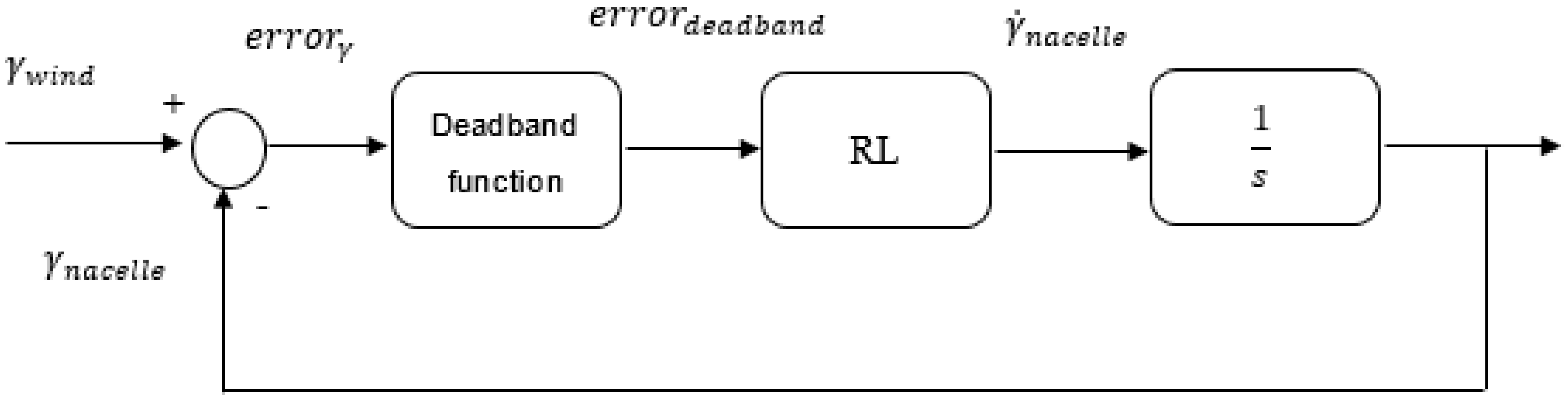
In this paper, due to the problems introduced by the integral action in yaw control systems, a simple proportional gain based control technique is considered as the conventional yaw angle control strategy. The pipeline and the block diagram of the operation principle of this technique, from now on named I regulator due to the integrator introduced by the mechanical actuator of the yawing system, are represented in Figure 6 and Figure 7, respectively.
The first step of the I regulator is the calculation of the yaw angle. Actually the yaw angle is not directly measured but it is calculated as the difference between the orientation of the main component of the incoming wind and the orientation of the nacelle of the wind turbine, as shown in Equation (3).
The incoming wind angle is measured by the meteorological station located on the top of the nacelle. It must be noticed that the anemometer and the weather vane of this meteorological station can be highly perturbed by the wake left by the wind turbine rotation. Schottler et al. [20] carry out an analysis of the wakes generated by two different wind turbines, including cases of yaw misalignment. Due to the high frequency components present on these wakes, measurements of the vane could be affected, and, hence, incorrect high frequency data of incoming wind orientation could be introduced to the yaw angle control system. As a result, yaw actuator would constantly respond to unreal high frequency wind direction variations. These fast movements of the actuator could derive in the fracture of the mechanism gears. A correct measurement of the wind direction must be ensured if an acceptable performance of the I regulator control algorithm is desired.
The next step is deadband function processing, as indicated in the pipeline of Figure 6. The objective of this step is to avoid unnecessary responses of the yaw actuator. Karakasis et al. [15] present the relationship between the yaw angle and the mechanical power that the wind turbine extracts from the small wind. If this relationship is analysed in detail, it is observed that small yaw angle errors lead to low reductions in the extracted mechanical power. Hence, the introduction of a deadband function ensures that the yawing system responds only when the error is significant. As a consequence, the number of actuations of the yaw mechanism is reduced and a longer lifetime of the mechanical components of the wind turbine is achieved. The expression corresponding to the deadband function is described in Equation (4).
When the deadband function step is over, an error signal is introduced to the controller. In this case, due to the problems of the integral action previously described in this section, the I regulator is based on a simple proportional gain controller. The signal given to the actuator is the rotational speed of the nacelle, as described by Equation (5).
In the last step, in order to close the loop, the position of the nacelle has to be measured to obtain a feedback. In this case, to the end of avoiding the introduction of additional hardware devices, that is an encoder sensor, the speed of the nacelle is directly integrated in the Laplace domain and the position is calculated as given by Equation (6).
It must be noted that the calculated values of the angular position of the nacelle, (deg), are limited to the range [90°, −90°], so the obtained results can be correctly interpreted and are consistent with the wind direction variations that have been considered for the analysis.
4. Basis of the Proposed Yaw Control Strategy
In this section, the basis of the proposed yaw control strategy based on the RL Q-Learning algorithm is presented. The objective of the developed strategy is to achieve a fully automatic tuning of the yaw control system of a wind turbine, in such a way that it is ensured that the system takes the best possible action in any concrete situation. As a result, the necessity of designing a conventional controller is completely avoided. The knowledge to be provided to the control system of the turbine is acquired by training of the system with real or even simulated data. The block diagram corresponding to the general structure of the proposed algorithm is represented in Figure 8.
The RL based yaw control algorithm is intended to substitute the conventional control strategy presented in Section 3. In fact it has been designed to learn from data generated by the I regulator strategy, that is, try to learn how a given conventional control governs a systems. In the RL algorithm real or simulated data could be used in order to train the system and acquire the knowledge necessary for a later fully autonomous operation.
As it was already stated in Section 1 of this paper, different RL schemas and algorithms have been widely studied in the literature during last decades. In general, the objective of RL techniques is to learn to take the best action a for a given state s that maximizes an immediate reward value r as shown in Figure 9. To ensure the selection of the best action, the Q-Learning RL algorithm defines a function Q: S × A → R, where S is the state space and A is the available actions set. According to Liu et al. [25], the definition of the reinforcement matrix is the main difference between the Q-Learning and SARSA algorithms. In most of the cases, including the Q-Learning algorithm, the state and the action variables are quantified, so the function Q(·) becomes the matrix Q(s,a). Nevertheless, in other algorithms such as SARSA, the function Q(s(t),a(t)) is defined as an exponential moving average of the immediate reward function R(t) return from instant t to ∞. So Q(s(t),a(t)) is the reward that the control system is going to achieve from instant t to ∞, from a given state s(t), if the control takes the action a(t).
In this paper, the conventional RL Q-Learning algorithm has been modified in order to keep the matrix Q(s,a) as a function, as shown in Figure 10. For this purpose an ANN has been trained to learn the content of the matrix Q(s,a). The most important advantage of keeping it as a function is to avoid quantification problems. A quantified function Q(s,a) becomes a matrix in which all the elements must be estimated. This approach imposes to carry out many simulations or to collect big amounts of real data. As a result, there are many reasons that prevent applying this approach. The first one is that the calculation of many scenarios would be necessary because the total number of elements of Q(s,a) when it is quantified as a matrix is the product of the number of possible actions and the number of possible states. This circumstance would require a big memory size just to store all these possible scenarios, since each element of the matrix Q(s,a) is a scenario that should be calculated. Secondly, a quantified matrix Q(s,a) could include non-possible actions for a given state that would not assure the integrity of a real system.
In the proposed RL algorithm, the reinforcement function Q(s(t),a(t)) at instant t, for a given state s(t) and action a(t) is defined as follows:
- -
- The state s(t), given in Equation (7), is defined as the difference between the orientation of the wind and the nacelle at instant t, as described in Equation (3).
- -
- The action a(t), given in Equation (8), is defined as the nacelle correction rotational speed at instant t.
The formal mathematical definition of the function Q(s(t),a(t)), given in Equation (9), is an exponential moving average from instant t to a time horizon t + T. This function has a discount factor typically expressed by , which in this case is set to one, because it is considered that all rewards are equally important for every time instant.
The immediate reward function for this application is defined as the mean power increase (%) obtained by the wind turbine when the yaw angle control is performed. Thus, three different scenarios (Power_control (t) (W), Power_no_control (t) (W) and Power_no_deviation (t) (W)) are considered for the power generated by the wind turbine. In each one of these scenarios the power generated by the wind turbine is calculated using the wind speed value and the yaw angle value corresponding to that scenario, as described by Equation (2) and Figure 3.
Power_control (t) is the power generated by the wind turbine when the turbine operates with the yaw angle command given by the yaw control. Power_no_control (t) is the power generated by the wind turbine when the angle of the nacelle is constant independently of the direction of the incoming wind, that is, no yaw control is performed. Finally Power_no_deviation (t) is the power generated by the wind turbine in the case that the nacelle would be always perfectly aligned with the incoming wind, which means that the yaw angle is zero.
If only possible power losses due to misalignments of the nacelle with respect to the incoming wind are taken into account, the value of Power_no_deviation (t) corresponds to the maximum power that can be generated by the wind turbine for a specific wind speed value. Hence, Power_control (t) and Power_no_control (t) should be as much as the same as Power_no_deviation (t).
The definition of the reward function for this application is given by Equation (10).
where the time slot value h can be calculated as T/N, being N the number of time samples in the time horizon T.
Finally, the Q(s(t),a(t)) function can be defined as follows in Equation (11).
It must be noted that the power (W) captured and hence generated by the wind turbine, depends not only on the yaw angle (deg) but also on the yaw angle correction action (deg/s) of the nacelle.
5. Synthesis of the Proposed Yaw Control Strategy
The first step of the proposed algorithm is the calculation of the time independent Q(s,a) matrix, with the objective of its posterior implementation through an ANN. To the end of calculating the matrix Q(s,a), real/simulation data of the variables necessary to design the RL control algorithm (the yaw angle (deg), the nacelle correction angular speed (deg/s) and the power generated by the wind turbine (W)) must be obtained.
In this analysis, the I regulator conventional yaw control strategy described in Section 3 of this paper has been taken as the basis for the collection of simulation data. A block diagram of the operating principle of the I regulator was presented in Figure 7. An example of the wind speed and wind direction data used for the simulations have already been presented in Figure 4 and Figure 5, respectively. Different scenarios could be considered for the simulations. In this case, it has been settled that the yaw control will be performed every 24 h, that is, the time horizon is set to 24 h and the simulation time has been set to 6 × 10⁶ s (69 days), that is, 69 nacelle orientation changes will be obtained in each simulation, which means that 69 time horizons have been proposed. Furthermore, the effect of different yaw controller values has also been considered. It must be recalled that the matrix Q(s,a) represents the experience for all states s and all possible actions a. For that purpose, several simulations have been carried out, each one with a different value of the proportional gain of the I regulator, as described in Equation (5). The limitations of the yawing system rate and the mechanical loads due to the yawing on the different elements of the wind turbine should be considered when setting this proportional controller value.
The results of one simulation are presented in Figure 11 and Figure 12. Figure 11 shows the tracking of the wind direction performed by the wind turbine every 24 h using the I regulator with the proportional gain set to . Figure 12 depicts the values of the power generated by the wind turbine in the 3 different scenarios (Power_control, Power_no_control and Power_no_deviation) used in Equation (11). As it can be clearly seen in the detailed view attached to the Figure 12, the power losses due to the misalignment between the incident wind and the turbine are reduced in the scenario Power_control compared to the scenario Power_no_control and the power generated by the wind turbine gets closer to the ideal scenario Power_no_deviation.
If wind direction variations of different magnitudes are introduced to the system, the effect of the yaw control on the power produced by the wind turbine for different yaw angle values can be analysed. In the same way, if the same simulation with the only variation of the proportional gain set to a different value is carried out, the effect of the nacelle correction rotational speed on the power produced by the wind turbine can be observed. The matrix Q(s,a) proposed in this paper is defined as the power gain (%) achieved by the wind turbine when the yaw control is enabled for different yaw angle (deg) and nacelle correction rotational speed (deg/s) values. Two different wind realizations have been proposed to obtain data for the calculation of the matrix Q(s,a), each one with 69 time horizons and 10 different values for the proportional gain . Consequently, 1380 data tuples are obtained and illustrated in the Figure 13 as the matrix Q(s,a).
It is important to note that the final objective of the RL algorithm introduced in this paper is not to imitate the performance of the I regulator algorithm but to learn from the experience produced by it and automatically design an optimal yaw controller.
Once the matrix Q(s,a) has been calculated, its implementation in an ANN is carried out. ANN based modelling present many advantages in comparison to function based modelling techniques. First, ANNs allow accurate modelling of highly irregular surfaces, which is not feasible with conventional function based modelling techniques, such as the so called Gibbs phenomenon. Moreover, due to the simplicity of the training process of an ANN, real time acquisition of new simulated/experimental data can be performed in order to improve the calculation of the matrix Q(s,a). In this way, that matrix can be recalculated online as the data is acquired in an incremental way. The same case with conventional modelling could extensively increment the complexity of the model. Finally, the access to the stored data turns to be faster in a model based on an ANN than in a model based on analytical functions, as a consequence of the reduced number of mathematical operations to be performed by the microcontroller. The selected topology for the ANN is the MultiLayer Perceptron with BackPropagation algorithm (MLP-BP). A detailed explanation of the Backward Propagation training algorithm is given by Savich et al. [35]. For this particular case, the designed ANN has two inputs (the yaw angle (deg) and the nacelle correction angular speed (deg/s)) and one output (power increase (%) when yaw control is performed). The MLP-BP neural network presents no feedback and consists of two input neurons, one hidden layer with 10 neurons and one unique linear output neuron. The activation function of the hidden neurons is the hyperbolic tangent function.
The data used for the training of the ANN has been obtained from temporal simulations of the I regulator conventional controller in the Matlab/Simulink environment. The ANN has been trained with the dataset of 1380 tuples obtained for the calculation of the matrix Q(s,a) represented in Figure 13. The data distribution for the training process of the ANN has been set to 70% for training, 15% for validation and the last 15% for test. The selected learning algorithm is the gradient descend, in which the learning ratio µ has been set to 0.1.
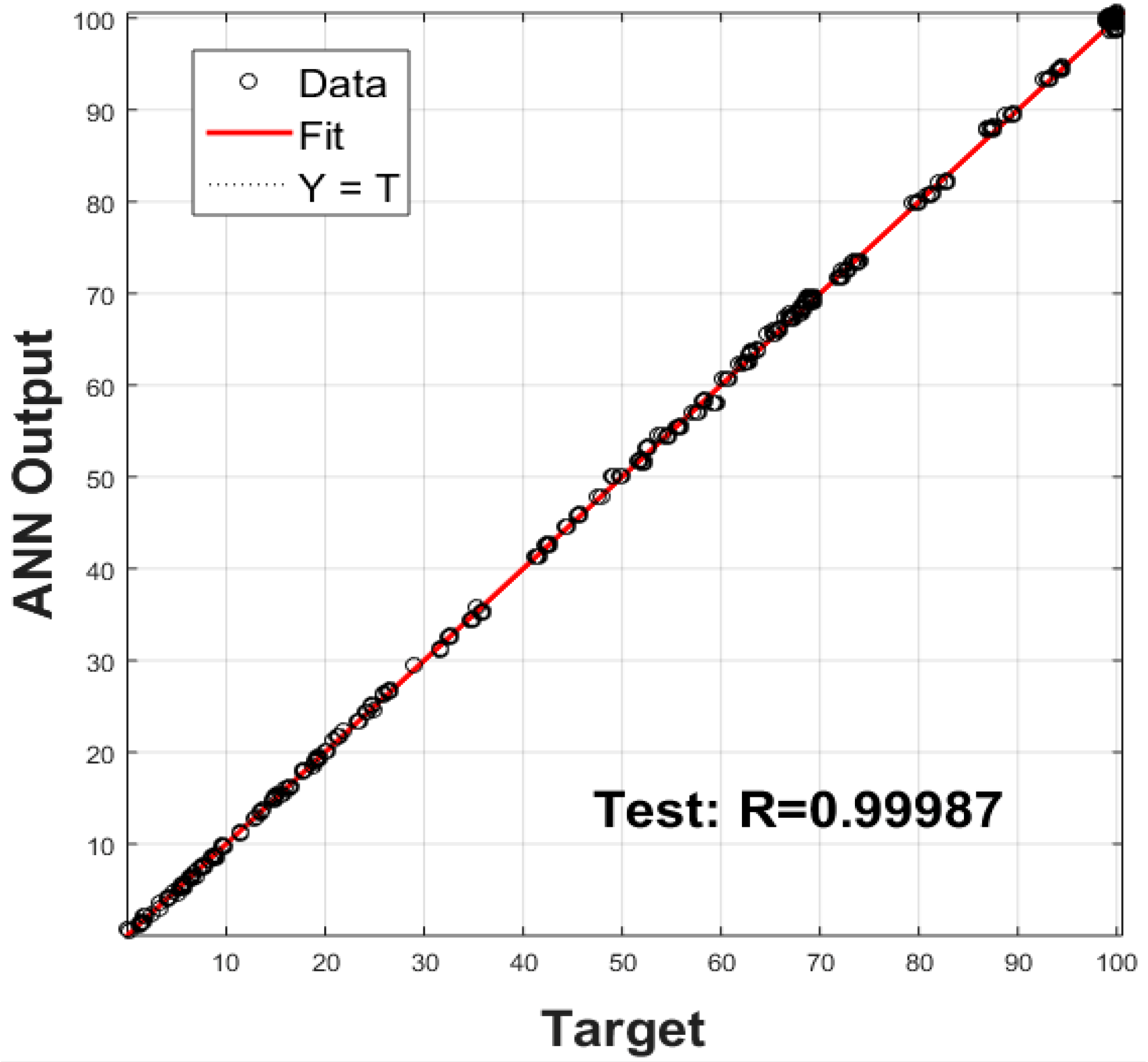
A comparison between the simulated power increase (%) data and the values obtained by the ANN is presented in Figure 14. The correlation coefficient obtained by the ANN, as illustrated in Figure 15, is equal to 0.99993. In the same way, the Mean Squared Error (MSE) associated to the performance of the ANN is equal to 1.5157. The high value of the correlation coefficient and the small value of the MSE indicate the high exactitude of the ANN and means it is suitable to store the data of the Q(s,a) matrix corresponding to the RL algorithm.
The estimated output value given by the ANN will be used by the RL algorithm implemented in the yaw control system of the wind turbine to select the best yawing correction angular speed in a given yaw angle state. The storage of the matrix Q(s,a) in an ANN as a continuous function Q(s(t),a(t)) prevents the system from having quantification problems, as well as reducing the memory size needed to store values corresponding to all real/simulated scenarios.
6. Comparison between Conventional and Proposed Novel Yaw Control Strategies
In this section, a comparison between the performances of the conventional yaw control algorithm, that is the I regulator and the proposed RL based yaw control algorithm is presented. For that purpose, temporal simulations have been carried out in Matlab/Simulink. In order to have an objective and realistic validation of the performance of the designed novel yaw control technique, a new wind realization, different from those used for the design of the controller, has been defined with TurbSim software tool [28]. The simulation results are represented in Figure 16 [29].
If the results presented in Figure 16 are analysed it is evident that while the performance of the I regulator is dependent on the proportional gain , the RL based control technique takes the best action in every case. The black line of Figure 16 corresponds to a small , while the green line, which is overlapped by the red line, corresponds to a higher . The response of the system with the higher gain, which coincides with the response given by the designed RL control algorithm, is faster and the power production is increased.
The first and main advantage associated to the RL control algorithm compared to conventional yaw control techniques is the lack of a manual control design process associated to the novel control algorithm introduced in this paper. While for the I regulator algorithm an appropriate proportional controller gain needs to be selected, the design of the RL based control algorithm is fully autonomous and there is no need for parameters tuning. All the experimental information is stored in the ANN and the system learns from this experience and takes the best action in every case.
Furthermore, when the I regulator is used, the designed yaw controller proportional gain can result to be non-optimal, as it is illustrated in Figure 16. If is selected too small, then the response of the system becomes too slow and the power production is not maximized. In other words, with the I regulator algorithm there is no security that the best action is taken for every yaw angle state, which, indeed, is ensured by the RL based control technique introduced in this paper. A comparison between the electrical energy generated by the wind turbine with the RL controller and a non-optimal I regulator for the simulated 6 × 10⁶ s (69 days) is presented in Table 2.
The results presented in Table 2 show that the RL controller achieves a generated energy increment of 1.39% in comparison to the non-optimal conventional control strategy during the 69 days of operation of the wind turbine. It must be noted that in the case of the I regulator the value of the energy generated by the wind turbine depends on the selected value of the proportional controller gain . Nevertheless, in the case of the RL controller the risk of a non-optimal design is erased since the algorithm is able to learn automatically and maximize the value of the generated energy.
7. Conclusions
A novel RL based algorithm for the yaw angle control of a wind turbine has been introduced and validated through simulation in this paper. The developed control strategy has been programmed to use data from simulations of the operation of a conventional yaw control system to use it as experimental data to train the system and autonomously obtain the matrix Q(s,a). Moreover, in order to avoid quantification problems, the matrix Q(s,a) has been implemented as a continuous function Q(s(t),a(t)) in a MLP-BP artificial neural network.
The design process of the introduced novel RL controller is applicable to all type of wind turbines operating in every kind of wind scenario. In fact, the basis of the proposed design process is to obtain data from different simulation scenarios of a conventional yaw control system and feed it to the RL algorithm to be used as experimental data and learn from it. The only wind turbine specific parameter necessary to complete the learning of the RL controller is the power curve, which is of common access for all type of wind turbines. The replacement in the simulations of the value of the power curve enables to easily adapt the design process from one system topology to another. Furthermore, the use of the power curve of the wind turbine allows every point of the operation of the wind generation system to be defined and, thus, makes the design process independent of the wind scenario. Experimental data can be collected from the real wind turbine and be directly fed to the RL controller, so the learning process keeps going even if the turbine has already been installed. Moreover, if experimental data cannot be collected, simulations of the operation of the wind turbine can be carried out and simulation data can be fed to the RL controller for the learning process, as it has been shown in this paper.
The validation results obtained in this paper through simulation with the Matlab/Simulink environment have been positive and show that the designed control strategy is suitable for the control of the yaw angle in wind turbines exposed to different wind scenarios. Furthermore, the designed RL based advanced control algorithm has shown to overcome one of the most important drawbacks of the conventional control strategies, that is, the necessity for control parameters tuning. An inadequate tuning of parameters in yaw control can generate some important problems in wind turbine operation. On the one hand, the power generation can be unnecessarily reduced if the yaw control is set to be too slow. On the other hand, the large mechanical loads in the elements of the yaw system can increase the fatigue if the yaw control is set to be too fast. To avoid these problems, the RL controller introduced in the current work is intended to learn from experience and remove the issues related to the tuning of the control parameters.
Author Contributions
A.S.-A. developed the Software, the Validation steps and the Original Writing Draft; E.Z. and U.F.-G. developed the Conceptualization, the Formal Analysis and the Supervision; J.L. and J.M.L.-G. collaborated on the Writing-Review & Editing and Supervision.
Funding
This research was partially funded by Foundation VITAL Fundazioa.
Acknowledgments
The authors want to express their gratitude to Argolabe Ingenieria SL for their collaboration with this work. This company has collected all the experimental data for this development.
Conflicts of Interest
The authors declare no conflict of interest.
References
- Lopez-Guede, J.M.; Ramos-Hernanz, J.A.; Zulueta, E.; Fernandez-Gamiz, U.; Oterino, F. Systematic modeling of photovoltaic modules based on artificial neural networks. Int. J. Hydrogen Energy 2016, 41, 12672–12687. [Google Scholar] [CrossRef]
- Lopez-Guede, J.M.; Ramos-Hernanz, J.A.; Zulueta, E.; Fernandez-Gamiz, U.; Azkune, G. Dual model oriented modeling of monocrystalline PV modules based on artificial neuronal networks. Int. J. Hydrogen Energy 2017, 42, 18103–18120. [Google Scholar] [CrossRef]
- Ramos-Hernanz, J.A.; Lopez-Guede, J.M.; Barambones, O.; Zulueta, E.; Fernandez-Gamiz, U. Novel control algorithm for MPPT with Boost converters in photovoltaic systems. Int. J. Hydrogen Energy 2017, 42, 17831–17855. [Google Scholar] [CrossRef]
- Munteanu, I.; Bratcu, A.I.; Cutululis, N.A.; Ceanga, E. Optimal Control of Wind Energy Systems Towards a Global Approach; Springer: London, UK, 2008; Volume XXII, p. 286. ISBN 978-1-84800-079-7. [Google Scholar]
- Jafarnejadsani, H.; Pieper, J. Gain-Scheduledℓ1-Optimal Control of Variable-Speed-Variable-Pitch Wind Turbines. IEEE Trans. Control Syst. Technol. 2015, 23, 372–379. [Google Scholar] [CrossRef]
- Merabet, A.; Eshaft, H.; Tanvir, A.A. Power-current controller based sliding mode control for DFIG-wind energy conversion system. IET Renew. Power Gener. 2018, 12, 1155–1163. [Google Scholar] [CrossRef]
- Gonzalez-Gonzalez, A.; Etxeberria-Agiriano, I.; Zulueta, E.; Oterino-Echavarri, F.; Lopez-Guede, J.M. Pitch Based Wind Turbine Intelligent Speed Setpoint Adjustment Algorithms. Energies 2014, 7, 3793–3809. [Google Scholar] [CrossRef] [Green Version]
- Ma, Z.; Yan, Z.; Shaltout, M.L.; Chen, D. Optimal Real-Time Control of Wind Turbine during Partial Load Operation. IEEE Trans. Control Syst. Technol. 2015, 23, 2216–2226. [Google Scholar] [CrossRef]
- Fernandez-Gauna, B.; Fernandez-Gamiz, U.; Grana, M. Variable speed wind turbine controller adaptation by reinforcement learning. Integr. Comput. Aided Eng. 2017, 24, 27–39. [Google Scholar] [CrossRef]
- Abouheaf, M.; Gueaieb, W.; Sharaf, A. Model-free adaptive learning control scheme for wind turbines with doubly fed induction generators. IET Renew. Power Gener. 2018, 12, 1675–1686. [Google Scholar] [CrossRef]
- Geng, H.; Yang, G. Output Power Control for Variable-Speed Variable-Pitch Wind Generation Systems. IEEE Trans. Energy Convers. 2010, 25, 494–503. [Google Scholar] [CrossRef]
- Astolfi, D.; Castellani, F.; Terzi, L. Wind Turbine Power Curve Upgrades. Energies 2018, 11, 1300. [Google Scholar] [CrossRef]
- Terzi, L.; Lombardi, A.; Castellani, F.; Astolfi, D. Innovative methods for wind turbine power curve upgrade assessment. J. Phys. Conf. Ser. 2018, 1102, 012036. [Google Scholar] [CrossRef]
- Song, D.; Fan, X.; Yang, J.; Liu, A.; Chen, S.; Joo, Y.H. Power extraction efficiency optimization of horizontal-axis wind turbines through optimizing control parameters of yaw control systems using an intelligent method. Appl. Energy 2018, 224, 267–279. [Google Scholar] [CrossRef]
- Karakasis, N.; Mesemanolis, A.; Nalmpantis, T.; Mademlis, C. Active yaw control in a horizontal axis wind system without requiring wind direction measurement. IET Renew. Power Gener. 2016, 10, 1441–1449. [Google Scholar] [CrossRef]
- Shariatpanah, H.; Fadaeinedjad, R.; Rashidinejad, M. A New Model for PMSG-Based Wind Turbine with Yaw Control. IEEE Trans. Energy Convers. 2013, 28, 929–937. [Google Scholar] [CrossRef]
- Masson, C.; Smalili, A. Numerical study of turbulent flow around a wind turbine nacelle. Wind Energy 2006, 9, 281–298. [Google Scholar] [CrossRef]
- Ozdemir, H.; Bot, E.T.G. An advanced method for wind turbine wake modelling. In Proceedings of the 2018 Wind Energy Symposium, Kissimmee, FL, USA, 8–12 January 2018. [Google Scholar]
- Bartl, J.; Mühle, F.; Schottler, J.; Sætran, L.; Peinke, J.; Adaramola, M.; Hölling, M. Wind tunnel experiments on wind turbine wakes in yaw: Effects of inflow turbulence and shear. Wind Energy Sci. 2018, 3, 329–343. [Google Scholar] [CrossRef]
- Schottler, J.; Bartl, J.; Muhle, F.; Saetran, L.; Peinke, J.; Hoelling, M. Wind tunnel experiments on wind turbine wakes in yaw: Redefining the wake width. Wind Energy Sci. 2018, 3, 257–273. [Google Scholar] [CrossRef]
- Bartl, J.; Muhle, F.; Saetran, L. Wind tunnel study on power output and yaw moments for two yaw-controlled model wind turbines. Wind Energy Sci. 2018, 3, 489–502. [Google Scholar] [CrossRef]
- Urban, A.M.; Larsen, T.J.; Larsen, G.C.; Held, D.P.; Dellwik, E.; Verelst, D. Optimal yaw strategy for optimized power and load in various wake situations. J. Phys. Conf. Ser. 2018, 1102, 012019. [Google Scholar] [CrossRef]
- Annoni, J.; Bay, C.; Taylor, T.; Pao, L.; Fleming, P.; Johnson, K. Efficient Optimization of Large Wind Farms for Real-time Control. In Proceedings of the 2018 Annual American Control Conference (ACC), Milwaukee, WI, USA, 27–29 June 2018; pp. 6200–6205. [Google Scholar]
- Munters, W.; Meyers, J. Dynamic Strategies for Yaw and Induction Control of Wind Farms Based on Large-Eddy Simulation and Optimization. Energies 2018, 11, 177. [Google Scholar] [CrossRef]
- Liu, C.; Xu, X.; Hu, D. Multiobjective Reinforcement Learning a Comprehensive Overview. IEEE Trans. Syst. Man Cybern. Syst. 2015, 45, 385–398. [Google Scholar]
- Watkins, C.J.; Dayan, P. Q-learning. Mach. Learn. 1992, 8, 279–292. [Google Scholar] [CrossRef] [Green Version]
- Adam, S.; Busoniu, L.; Babuska, R. Experience Replay for Real-Time Reinforcement Learning Control. IEEE Trans. Syst. Man Cybern. Part C 2012, 42, 201–212. [Google Scholar] [CrossRef]
- Kelley, N.; Jonkman, B. NWTC Computer-Aided Engineering Tools (TurbSim). 2012. Available online: http://wind.nrel.gov/designcodes/preprocessors/turbsim (accessed on 17 January 2016).
- Fernandez-Gamiz, U.; Zulueta, E.; Boyano, A.; Ansoategui, I.; Uriarte, I. Five Megawatt Wind Turbine Power Output Improvements by Passive Flow Control Devices. Energies 2017, 10, 742. [Google Scholar] [CrossRef]
- IEC 61400-1. Wind Turbine Generator Systems-Part 1: Safety Requirements, 2nd ed.; International Electrotechnical Commission: Geneva, Switzerland, 1999. [Google Scholar]
- Manwell, J.F.; McGowan, J.G.; Rogers, A.L. Wind Energy Explained: Theory, Design and Application, 2nd ed.; John Wiley & Sons: Hoboken, NJ, USA, 2011. [Google Scholar]
- Damiani, R.; Dana, S.; Annoni, J.; Fleming, P.; Roadman, J.; Dam, J.V.; Dykes, K. Assessment of wind turbine component loads under yaw-offset conditions. Wind Energy Sci. 2018, 3, 173–189. [Google Scholar] [CrossRef] [Green Version]
- Bharani, R.; Jayasankar, K.C. Yaw Control of Wind Turbine Using Fuzzy Logic Controller. Power Electron. Renew. Energy Syst. 2015, 326, 997–1006. [Google Scholar]
- Song, D.; Yang, J.; Fan, X.; Liu, Y.; Liu, A.; Chen, G.; Joo, Y.H. Maximum power extraction for wind turbines through a novel yaw control solution using predicted wind directions. Energy Convers. Manag. 2018, 157, 587–599. [Google Scholar] [CrossRef]
- Savich, A.W.; Moussa, M.; Areibi, S. The Impact of Arithmetic Representation on Implementing MLP-BP on FPGAs: A Study. IEEE Trans. Neural Netw. 2007, 18, 240–252. [Google Scholar] [CrossRef]
Figure 1.
Wind Turbine of 100 kW placed in Bodegas Pierola wine cellar (Moreda, Araba, Spain).

Figure 2.
(a) Generated power (W)—Wind speed (m/s) real measurements of the wind turbine; (b) Generated power curve of the wind turbine.
Figure 2.
(a) Generated power (W)—Wind speed (m/s) real measurements of the wind turbine; (b) Generated power curve of the wind turbine.

Figure 3.
Wind turbine generated power model.

Figure 4.
Wind data series generated with TurbSim tool.

Figure 5.
Wind direction data series for the yaw control algorithm design.

Figure 6.
Pipeline of the operating principle of the conventional wind turbine yaw control of the I regulator.
Figure 6.
Pipeline of the operating principle of the conventional wind turbine yaw control of the I regulator.

Figure 7.
Block diagram of the conventional wind turbine yaw control of the I regulator.

Figure 8.
Block diagram of a RL based yaw control system.

Figure 9.
Basic operation of Reinforcement Learning algorithms.

Figure 10.
Block diagram of the proposed RL based yaw control system.

Figure 11.
Wind direction tracking performed by the I regulator for the yaw control of a wind turbine.
Figure 11.
Wind direction tracking performed by the I regulator for the yaw control of a wind turbine.

Figure 12.
Different scenarios of the generated power for the Q(s,a) matrix calculation.

Figure 13.
Graphical representation of the Q(s,a) matrix.

Figure 14.
Comparison between simulated data and the values obtained by the ANN.

Figure 15.
Regression coefficient of the ANN with training process values.

Figure 16.
Performance comparison of the conventional and the proposed RL based yaw control algorithms.
Figure 16.
Performance comparison of the conventional and the proposed RL based yaw control algorithms.


Table 1.
Parameters of the wind data series generation process in TurbSim.
| Hub height | 84 m |
| Mean wind speed at hub height | 7.5 m/s |
| Spectral model | IECKAI (B) |
| Analysis time | 6 × 10⁶ s |
| Time step | 1000 s |
Table 2.
Electrical energy generation comparison of the conventional and the proposed RL based yaw control algorithm.
Table 2.
Electrical energy generation comparison of the conventional and the proposed RL based yaw control algorithm.
| Case | Energy Generation (KW·h) | ∆Energy Generation (%) |
|---|---|---|
| I regulator Kp = 0.0001 | 3.4313 × 10⁴ | - |
| RL controller | 3.4790 × 10⁴ | 1.39 |
© 2019 by the authors. Licensee MDPI, Basel, Switzerland. This article is an open access article distributed under the terms and conditions of the Creative Commons Attribution (CC BY) license (http://creativecommons.org/licenses/by/4.0/).
Share and Cite
MDPI and ACS Style
Saenz-Aguirre, A.; Zulueta, E.; Fernandez-Gamiz, U.; Lozano, J.; Lopez-Guede, J.M. Artificial Neural Network Based Reinforcement Learning for Wind Turbine Yaw Control. Energies 2019, 12, 436. https://doi.org/10.3390/en12030436
AMA Style
Saenz-Aguirre A, Zulueta E, Fernandez-Gamiz U, Lozano J, Lopez-Guede JM. Artificial Neural Network Based Reinforcement Learning for Wind Turbine Yaw Control. Energies. 2019; 12(3):436. https://doi.org/10.3390/en12030436
Chicago/Turabian StyleSaenz-Aguirre, Aitor, Ekaitz Zulueta, Unai Fernandez-Gamiz, Javier Lozano, and Jose Manuel Lopez-Guede. 2019. "Artificial Neural Network Based Reinforcement Learning for Wind Turbine Yaw Control" Energies 12, no. 3: 436. https://doi.org/10.3390/en12030436
Note that from the first issue of 2016, this journal uses article numbers instead of page numbers. See further details here.