On-Board Cold Thermal Energy Storage System for Hydrogen Fueling Process †

Department of Environmental and Energy Systems, Korea Institute of Machinery and Materials, 156 Gajeongbuk-ro, Yuseong-gu, Daejeon 34104, Korea
*
Author to whom correspondence should be addressed.
†
This article is based on a paper presented at The Asian Symposium on Computational Heat Transfer and Fluid Flow (ASCHT) 2015, 22–25 November 2015.
Energies 2019, 12(3), 561; https://doi.org/10.3390/en12030561
Submission received: 30 December 2018
/
Revised: 2 February 2019
/
Accepted: 7 February 2019
/
Published: 12 February 2019
(This article belongs to the Special Issue Sustainable Hydrogen Production, Storage and Utilization)
Abstract
:The hydrogen storage pressure in fuel cell vehicles has been increased from 35 MPa to 70 MPa in order to accommodate longer driving range. On the downside, such pressure increase results in significant temperature rise inside the hydrogen tank during fast filling at a fueling station, which may pose safety issues. Installation of a chiller often mitigates this concern because it cools the hydrogen gas before its deposition into the tank. To address both the energy efficiency improvement and safety concerns, this paper proposed an on-board cold thermal energy storage (CTES) system, cooled by expanded hydrogen. During the driving cycle, the proposed system uses an expander, instead of a pressure regulator, to generate additional power and cold hydrogen gas. Moreover, CTES is equipped with phase change materials (PCM) to recover the cold energy of the expanded hydrogen gas, which is later used in the next filling to cool the high-pressure hydrogen gas from the fueling station.
1. Introduction
A few years ago, the typical hydrogen storage pressure in fuel cell vehicles was 35 MPa [1]; such pressure produced a very low volumetric energy density to accommodate long-range driving [2] that would require 70 MPa. Recently, on-board hydrogen storage, mainly in high pressure of 70 MPa, has been widely adopted. This increase of pressure, however, leads to a significant rise in the temperature of the vehicle tank during fast filling at a fueling station due to heat of compression and Joule–Thomson expansion [2,3]. Pre-cooling hydrogen with a chiller before refueling mitigates the temperature rise to meet the maximum allowable tank temperature that conforms to international standards and regulations such as the Society of Automotive Engineers (SAE) protocol [4] and the International Organization for Standardization (ISO) safety code [5] (i.e., 85 °C) [2,3]. Such temperature rise during the filling process also reduces the total amount of gas stored inside the tank. In a series of experiments, Kim et al. [1] quantified temperature change on the cylinder of the tank using computational fluid dynamics (CFD) analysis. Miguel et al. [6] evaluated the effect of the filling rate on the gas temperature increase and investigated the thermal response of the metallic bosses and the external surface of the tanks under different cycling conditions. Monde et al. [7] validated their model via experiments and mentioned parameters affecting the filling process to determine the filling time or precooled temperature. In several refueling experiments, Zheng et al. [8] investigated the temperature rise during refueling and validated a CFD model; results showed that an increase in initial pressure and a decrease in ambient temperature lead to an approximately linear decrease in final gas temperature [8]. Moreover, Miguel et al. [9] investigated the influence of initial tank temperature on refueling of two different on-board hydrogen tanks, four different fuel delivery temperatures (from ambient temperature refueling to a pre-cooled hydrogen at −40 °C), several filling rates, and initial pressures. Xiao et al. [9] proposed a new analytical solution of pre-cooling hydrogen temperature from a simplified lumped parameter model, and investigated the effects of initial temperature, initial pressure, and the filling time on the inflow hydrogen temperature.
Installation of a pre-cooling system in a hydrogen refueling station invites cooling demand, thus significantly increasing the initial cost, as well as the running costs of the station, in terms of energy consumption [10]. Elgowainy et al. [11] conducted a techno-economic and thermodynamic analysis of hydrogen precooling units for T40 stations, and they examined the key factors that contribute to the cost and energy use of hydrogen precooling. Cebolla et al. [12] executed filling experiments with different inlet gas temperatures and mass flow rates and stated that the lowest precooling temperature (−40 °C) is not always required in order to meet the user’s requirements. To reduce the cooling demand at the fueling station, Melideo and Baraldi [10] proposed a convenient filling strategy, with an almost linear pressure rise and pre-cooling in the second half of the process, which achieved a 60% reduction of cooling energy demand compared to the entire filling pre-cooling by the CFD analysis.
On a parallel note, the storage system consumes more energy to compress hydrogen at higher pressures of 70 MPa. Because the energy consumed during filling cannot be recovered, energy efficiency at higher pressure storage decreases. According to the well-to-wheel analysis of fuel cell vehicles by Campanari et al. [13], the conversion efficiency of energy consumed at a refilling station (energy consumption for each kWh of energy given at the vehicle wheels) to compress hydrogen to 70 MPa from the pipeline (at 6 MPa) is 65%.
In this study, a recovery system for hydrogen pressure energy in a fuel cell vehicle is proposed. During pressure regulation in the vehicle, an expander is used to recover the pressure energy and produce additional power. In addition, the cold energy of expanded hydrogen is stored in an on-board cold thermal energy storage (CTES) system. It is later used to cool the high-pressure hydrogen gas before filling. Thus, it reduces (or eliminates) energy consumption by the chiller at the fueling station. A simple thermodynamic analysis is used to investigate the feasibility of the new system. The aim of this study is to show the potential energy-saving methods for fuel cell vehicles and measures of effectiveness, which have so far been difficult to find in the available literature.
2. System Configuration
Figure 1 shows the configuration of the pressure energy recovery system. During the driving cycle, hydrogen pressure from the tank to the fuel cell is reduced to less than 1 MPa typically by a pressure regulator; for the proposed system, an expander is used from P1 to P2 to produce additional power. During expansion, hydrogen temperature drops from T1 to T2; furthermore, the cold hydrogen from the expander passes through an on-board CTES system, freezing the phase change material (PCM). As shown in Figure 2, the temperature of expanded hydrogen increases from T2 to T3 through the CTES system, whereas in the PCM, phase change occurs at a constant temperature TS. Then, during the next filling process, the CTES system is used to cool the high-pressure hydrogen gas from T4 to T5 before filling, reducing (or eliminating) the energy consumption of the chiller at the fueling station.
SAE J2601 [4] defines the fueling station dispenser type by its capability to dispense hydrogen fuel at a specific nozzle pre-cooled temperature (Type A: −20 °C and Type B: −40 °C). In this study, T2 as a pre-cooled temperature was initially assumed to be −20 °C in order to investigate the feasibility of the system. Then, a method to achieve −40 °C of pre-cooled temperature was presented.
3. System Modeling
The following are the general assumptions considered in the analysis: The kinetic and potential energies, as well as the heat and friction losses, are negligible, and the expansion process is an adiabatic process. The properties of hydrogen were obtained from REFPROP–NIST [14]. The equations for the various components of the system are as follows.
The isentropic efficiency of the expander is defined as
where the subscript s denotes an isentropic expansion process. The pressure after the expander P2 is assumed to be 1 MPa.
The specific work of the expansion process is expressed as
Exergy can be defined as the maximum possible useful work that can be obtained during a process that brings the system into equilibrium while interacting solely with the environment. The specific exergy k of a hydrogen stream can be expressed as [15]
where h and s are the enthalpy and entropy, respectively, and the subscript 0 indicates that the properties are taken at the standard temperature and pressure (T0 = 20 °C, P0 = 1 bar) as a dead state.
The specific cooling capacity of expanded hydrogen is expressed as
The cooling requirement, to cool the high-pressure hydrogen from T4 to T5 during the filling process at the fueling station, is expressed as
where the PCM temperature TS and the temperature of hydrogen after the PCM cold storage T3 are assumed to be −25 °C and −30 °C, respectively, to cool the high-pressure hydrogen at the fueling station from 20 °C to −20°C. The pinch temperature between hydrogen and the PCM cold storage is assumed to be 5 °C.
The fuel efficiency improvement (FEI) due to the additional work done by expanding hydrogen can be evaluated as
where LHV indicates the lower heating value of hydrogen.
4. Results
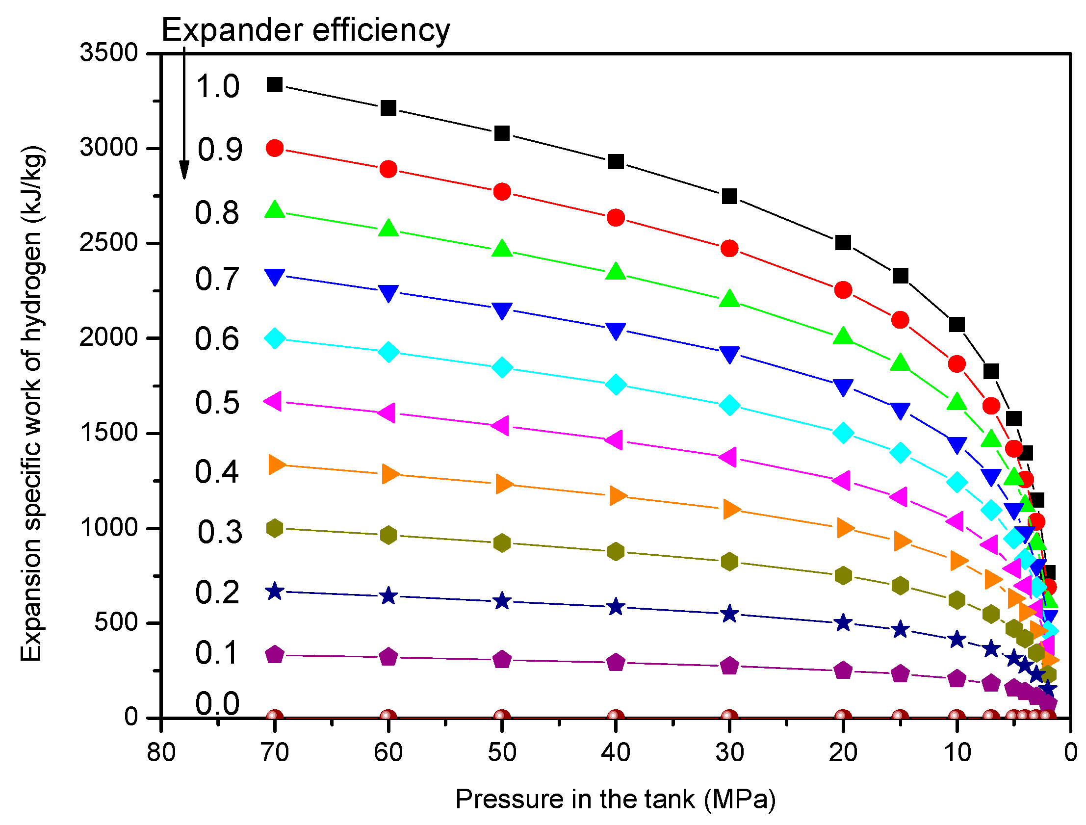
Figure 3 shows the expansion work of hydrogen in the vehicle tank for various expander efficiencies with respect to pressure. It was assumed above that hydrogen from the tank expands to 1 MPa through the expander. For a given expander efficiency, the expansion work decreases with a decrease in tank pressure. Correspondingly, for a given tank pressure, the expansion work is proportional to the expander efficiency.
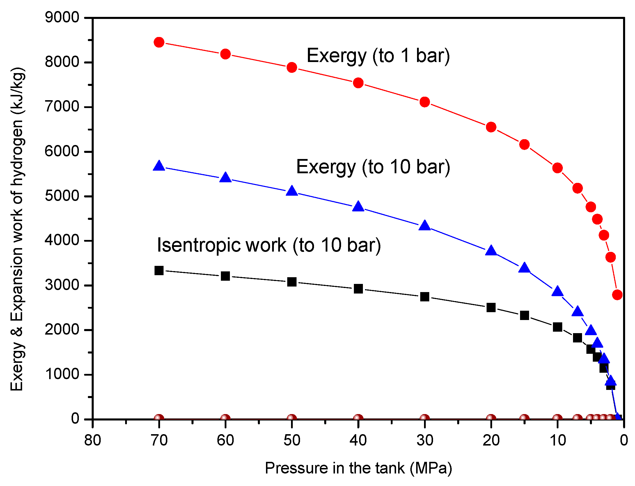
Figure 4 shows the exergy and isentropic expansion work of hydrogen. The exergy difference between the given tank pressure and the final pressure of 1 MPa, as the maximum available work from the expansion process, represents the ideal expansion work by an isothermal expansion. As shown in the figure, the ideal adiabatic (i.e., isentropic) expansion work is equal to about 60–70% of the exergy difference.
Although the expansion work by the adiabatic process is lower than that by an isothermal process, using the cold energy of expanded hydrogen in the vehicle is possible. Figure 5 shows the temperature of expanded hydrogen for various expansion efficiencies with respect to the pressure in the tank. In the case of free expansion (zero expander efficiency), the temperature rises owing to the Joule–Thomson expansion.
The maximum temperature drop by isentropic expansion (1.0 expander efficiency) from 70 MPa to 1 MPa is −201.6 °C. For a given pressure in the tank, the temperature drop is proportional to the expander efficiency. Similar to the characteristics of the expansion work, for a given expander efficiency, the temperature drop decreases with a decrease in tank pressure.
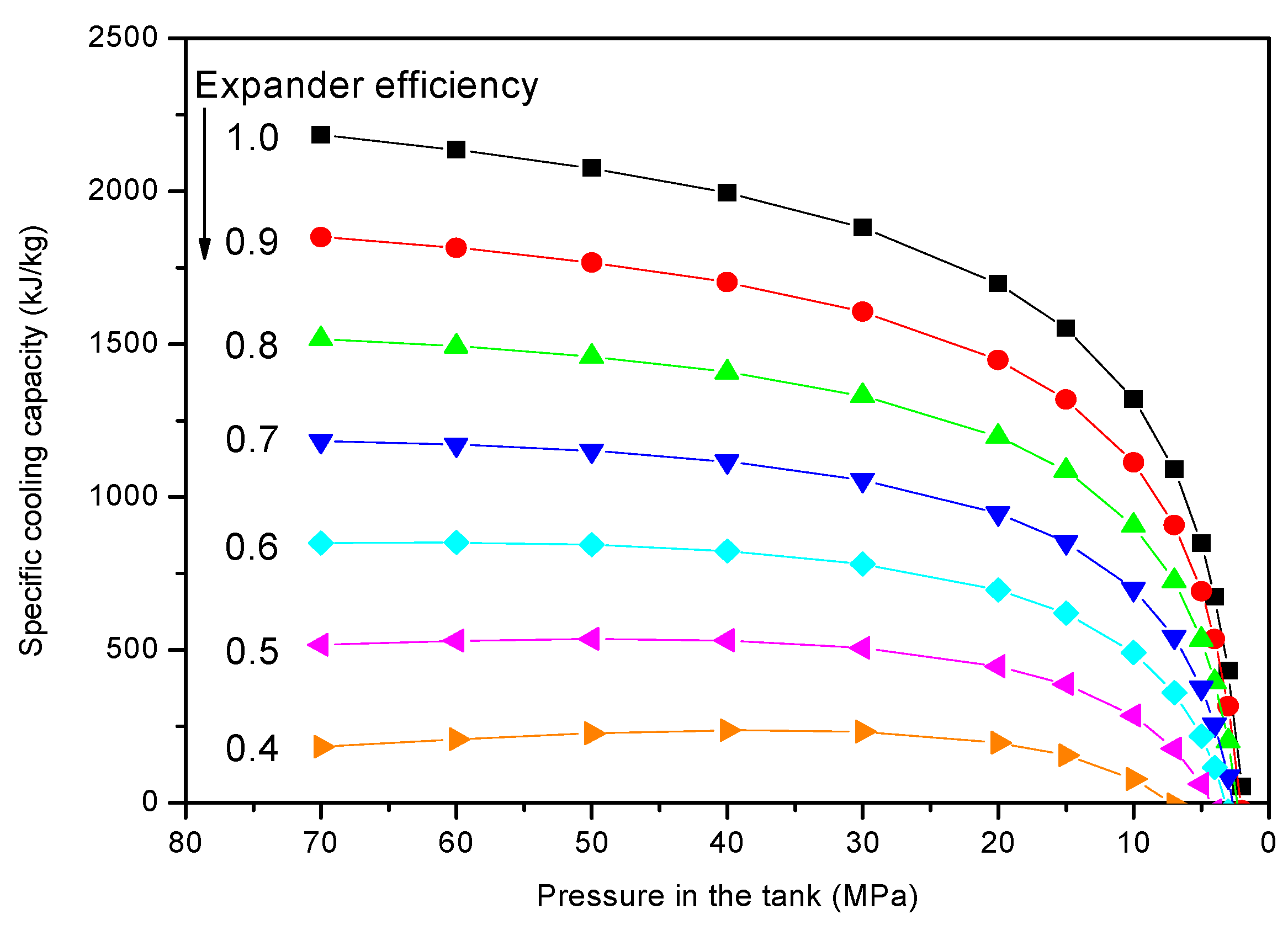
Because the expansion work and cooling capacity of the expanding hydrogen decreases during the discharging period from 70 MPa to 1 MPa, calculating the mean values of the expanding hydrogen expanding hydrogen is useful. Figure 6 shows the specific cooling capacity of the expanded hydrogen for various expander efficiencies with respect to the tank pressure.
Figure 7 shows the mean expansion work and cooling capacity of hydrogen with respect to expander efficiency. At an expander efficiency of 0.53, the expansion work is 1671.3 kJ/kg. In order to replace the use of the chiller at the fueling station, the minimum cooling requirement from 20 °C to −20 °C at 70 MPa, neglecting the loss of the CTES system, is 600.7 kJ/kg.
As shown, if the expander efficiency gets higher than 0.53, it is possible to meet this requirement. On the contrary, given that the cooling capacity of the CTES system is realistically unable to do so, it can alternatively reduce the energy consumption of the chiller at the fueling station. Thus, it is possible to selectively use the chiller by monitoring the hydrogen temperature after the CTES system.
Figure 8 shows the fuel efficiency improvement due to the additional work done in the vehicle by the expanding hydrogen. Note that at expander efficiencies of 0.53 and 1.0, the fuel efficiency improvements are 1.39 % and 2.63 %, respectively.
The CTES system uses PCM to minimize its volume and weight. Table 1 list the properties of the PCM model PCM-HS26N by savENRGTM [16], and its volume and weight of 9.7 L and 11.6 kg, respectively, necessary to meet the cooling requirement for 100 L and 70 MPa of hydrogen storage and replace the chiller at the fueling station.
Although the minimum cooling requirement considered disregarded losses in the CTES system, the real cooling capacity of the expanded hydrogen, compensating for these losses, must be increased. As shown in Figure 9, this can be achieved by employing two stages of PCM (−5 °C PCM1 and −25 °C PCM2) in the CTES system. Thus, the specific cooling capacity of the expanded hydrogen can be increased by 54% (from 600.7 kJ/kg to 924.8 kJ/kg) since its temperature after the PCM cold storage T3 can be increased from −30 °C to −10 °C.
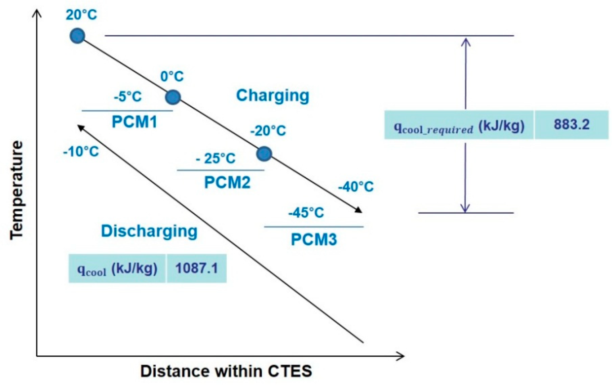
As pre-cooling temperature, T2 was initially assumed to be −20 °C. To achieve the lower temperature of −40 °C, the three stages of PCM (−5 °C PCM1, −25 °C PCM2, and −45 °C PCM3), shown in Figure 10, can be used. In doing so, the cooling capacity (1087.1 kJ/kg) is able to meet the minimum cooling requirement (883.2 kJ/kg) from 20 °C to −40 °C at 70 MPa, as in the previous calculation process.
5. Discussion
The results show that the proposed system for hydrogen pressure energy recovery in a fuel cell vehicle can reduce fuel consumption by providing additional power through the expander and can reduce the power consumption of the chiller at the refueling station through the on-board CTES system.
The 1.4–2.6% improvement in fuel efficiency with the hydrogen expander cannot be ignored because it means a 3–5% reduction in the fuel consumption of fuel cell vehicles. In the case of waste heat recovery (WHR) with an organic Rankine cycle (ORC) system, BOSCH promoted their system for commercial vehicles by highlighting the reduction in fuel consumption by as much as 5% and payback period within two years [17]. The reduction in fuel consumption by 5% means a 2% improvement in net fuel efficiency, considering 40% of engine efficiency. The WHR ORC system consists of many components including expander, pump, and many heat exchangers. The proposed hydrogen expander is much simpler than the WHR ORC system for additional power.
Nowadays, energy-saving technologies for vehicles using fossil fuels have been boosted by the stricter CO2 emissions regulations for vehicles in the near future. In the case of energy-saving technologies for the fuel cell vehicles, although there is no benefit in terms of CO2 emissions reduction, such technologies must be developed to reduce energy losses in the energy conversion processes of hydrogen as an energy carrier for transportation. From the point view of the customer, the on-board CTES system for the hydrogen fueling process does not offer any advantage if there is no discount in fuel cost or incentives. Otherwise, the on-board cold thermal energy storage can be used for the air-conditioning in vehicles. In reality, in order to boost this kind of energy-saving technologies, incentives or regulations should be provided to automobile companies and customers.
6. Conclusions
Hydrogen pressure in the storage system of a fuel cell vehicle has been increased from the past 35 MPa to a higher 70 MPa to realize longer driving ranges. However, such increase results in lower energy efficiency owing to the higher energy consumption needed for compression, as well as the use of a chiller to cool the hydrogen before filling at a fueling station. As a response, this study proposed a hydrogen pressure energy recovery system consisting of a hydrogen expander, instead of a regulator, and a cold thermal energy storage (CTES). Unlike the pressure regulator, the expander produces additional power, while the expanding-hydrogen-cooled on-board CTES system cools the gas before filling at the fueling station.
Some results from the simple thermodynamic analysis performed showed that at the expander efficiencies of 0.53 and 1.0, fuel efficiency respectively improved by 1.39% and 2.63%. Furthermore, the CTES could reduce (or dispense with) the energy consumption of the chiller at the fueling station. A phase change material (PCM) could be considered for the CTES because its volume and weight are feasible for the vehicle application.
Author Contributions
All authors contributed to this paper. Y.M.K. designed the simulations. D.G.S. and C.G.K. discussed the results and implications and commented on the manuscript in all stages.
Conflicts of Interest
The authors declare no conflict of interest.
Nomenclature
| FEI | Fuel efficiency improvement, - |
| h | Specific enthalpy, kJ/kg |
| k | Specific exergy, kJ |
| LHV | Lower heating value, kJ/kg |
| P | Pressure, kPa |
| Q | Heat transfer, kJ/kg |
| q | Specific heat transfer, kJ/kg |
| s | Specific entropy, kJ/kg·K |
| T | Temperature, K |
| w | Work, kJ |
| Special characters: | |
| η | Efficiency, - |
| Subscripts: | |
| 0 | Dead state |
| c,e | Cooling capacity of expanded hydrogen |
| cool | Cooling requirement |
| s | Isentropic process |
References
- Kim, S.C.; Lee, S.; Yoon, K.B. Thermal characteristics during hydrogen fueling process of type IV cylinder. Int. J. Hydrogen Energy 2010, 35, 6830–6835. [Google Scholar] [CrossRef]
- Paster, M.D.; Ahluwalia, R.K.; Berry, G.; Elgowainy, A.; Lasher, S.; McKenney, K.; Gardiner, M. Hydrogen storage technology options for fuel cell vehicles: Well-to-wheel costs, energy efficiencies, and greenhouse gas emissions. Int. J. Hydrogen Energy 2011, 36, 14534–14551. [Google Scholar] [CrossRef]
- Galassi, M.C.; Baraldi, D.; Iborra, B.A.; Moretto, P. CFD analysis of fast filling scenarios for 70 MPa hydrogen type IV tanks. Int. J. Hydrogen Energy 2012, 37, 6886–6892. [Google Scholar] [CrossRef]
- SAE J2601. Fueling Protocols for Light Duty Gaseous Hydrogen Surface Vehicles; SAE International: Warrendale, PA, USA, 1999. [Google Scholar]
- International Standard Organization. Gaseous Hydrogen and Hydrogen Blends Land Vehicle Fuel Tanks; ISO/TS 15869.2009; International Standard Organization: Geneva, Switzerland, 2009. [Google Scholar]
- De Miguel, N.; Ortiz Cebolla, R.; Acosta, B.; Moretto, P.; Harskamp, F.; Bonato, C. Compressed hydrogen tanks for on-board application: Thermal behaviour during cycling. Int. J. Hydrogen Energy 2017, 40, 6449–6458. [Google Scholar] [CrossRef]
- Monde, M.; Woodfield, P.L.; Takano, T.; Kosaka, M. Estimation of temperature change in practical hydrogen pressure tanks being filled at high pressures of 35 and 70 MPa. Int. J. Hydrogen Energy 2012, 37, 5723–5734. [Google Scholar] [CrossRef]
- Zheng, J.; Guo, J.; Yang, J.; Zhao, Y.; Zhao, L.; Pan, X.; Ma, J.; Zhang, L. Experimental and numerical study on temperature rise within a 70 MPa type III cylinder during fast refueling. Int. J. Hydrogen Energy 2013, 38, 10956–10962. [Google Scholar] [CrossRef]
- De Miguel, N.; Acosta, B.; Baraldi, D.; Melideo, R.; Ortiz Cebolla, R.; Moretto, P. The role of initial tank temperature on refuelling of on-board hydrogen tanks. Int. J. Hydrogen Energy 2016, 41, 8606–8615. [Google Scholar] [CrossRef] [Green Version]
- Melideo, D.; Baraldi, D. CFD analysis of fast filling strategies for hydrogen tanks and their effects on key-parameters. Int. J. Hydrogen Energy 2015, 40, 735–745. [Google Scholar] [CrossRef] [Green Version]
- Elgowainy, A.; Reddi, K.; Lee, D.Y.; Rustagi, N.; Gupta, E. Techno-economic and thermodynamic analysis of pre-cooling systems at gaseous hydrogen refueling. Int. J. Hydrogen Energy 2017, 42, 29067–29079. [Google Scholar] [CrossRef]
- Ortiz Cebolla, R.; Acosta, B.; de Miguel, N.; Moretto, P. Effect of precooled inlet gas and mass flow rate on final state of charge during hydrogen refuelling. Int. J. Hydrogen Energy 2015, 40, 4698–4706. [Google Scholar] [CrossRef]
- Campanari, S.; Manzolini, G.; Iglesia, F.G. Energy analysis of electric vehicles using batteries or fuel cells through well-to-wheel driving cycle simulations. J. Power Sources 2009, 186, 464–477. [Google Scholar] [CrossRef]
- REFPROP Version 9.1. NIST Standard Reference Database 23; The U.S. Secretary of Commerce: Washington, DC, USA, 2013.
- Borel, L.; Favrat, D. Thermodynamics and Energy System Analysis; EPFL Press: Lausanne, Switzerland, 2010; pp. 399–490. [Google Scholar]
- savENRGTM phase change materials. Available online: http://www.rgees.com/documents/aug_2013/savENRG%20PCM-HS26N.pdf (accessed on 3 March 2015).
- Robert BOSCH GmbH. Diesel Systems—Waste Heat Recovery System for Commercial Vehicles—Brochure. Available online: http://products.bosch-mobility-solutions.com (accessed on 27 April 2014).
Figure 1.
System configuration for hydrogen pressure energy recovery in a fuel cell vehicle.

Figure 2.
Temperature change of hydrogen through the CTES system with phase change materials.

Figure 3.
Expansion work of hydrogen as a function of tank pressure and expander efficiencies.

Figure 4.
Exergy and expansion work as a function of tank pressure.

Figure 5.
Temperature of expanded hydrogen as a function of tank pressure and expander efficiencies.
Figure 5.
Temperature of expanded hydrogen as a function of tank pressure and expander efficiencies.

Figure 6.
Cooling capacity of expanded hydrogen as a function of tank pressure and expander efficiencies.
Figure 6.
Cooling capacity of expanded hydrogen as a function of tank pressure and expander efficiencies.

Figure 7.
Mean expansion work and cooling capacity of hydrogen with respect to expander efficiency.

Figure 8.
Fuel efficiency improvements with respect to expander efficiency.

Figure 9.
Two-stages of PCM cold thermal energy storage (CTES) system for cooling capacity improvement.
Figure 9.
Two-stages of PCM cold thermal energy storage (CTES) system for cooling capacity improvement.

Figure 10.
Three-stages of PCM CTES system for −40 °C of pre-cooled temperature.


Table 1.
PCM properties, volume, and weight satisfying the cooling requirement of 100 L and 70 MPa hydrogen storage. PCM, phase change materials.
Table 1.
PCM properties, volume, and weight satisfying the cooling requirement of 100 L and 70 MPa hydrogen storage. PCM, phase change materials.
| PCM Properties | Hydrogen Storage | ||
|---|---|---|---|
| Melting Temp. (°C) | −25.6 | Volume (L) | 100 |
| Freezing Temp. (°C) | −26.2 | Gas weight (kg) | 3.97 |
| Liquid density (kg/m3) | 1200 | (kJ/kg) | 600.7 |
| Latent heat (kJ/kg) | 205 | (kJ) | 2384.3 |
| PCM volume and weight satisfying the cooling requirement | |||
| Volume (L) | 9.7 | ||
| Weight (kg) | 11.6 | ||
© 2019 by the authors. Licensee MDPI, Basel, Switzerland. This article is an open access article distributed under the terms and conditions of the Creative Commons Attribution (CC BY) license (http://creativecommons.org/licenses/by/4.0/).
Share and Cite
MDPI and ACS Style
Kim, Y.M.; Shin, D.G.; Kim, C.G. On-Board Cold Thermal Energy Storage System for Hydrogen Fueling Process. Energies 2019, 12, 561. https://doi.org/10.3390/en12030561
AMA Style
Kim YM, Shin DG, Kim CG. On-Board Cold Thermal Energy Storage System for Hydrogen Fueling Process. Energies. 2019; 12(3):561. https://doi.org/10.3390/en12030561
Chicago/Turabian StyleKim, Young Min, Dong Gil Shin, and Chang Gi Kim. 2019. "On-Board Cold Thermal Energy Storage System for Hydrogen Fueling Process" Energies 12, no. 3: 561. https://doi.org/10.3390/en12030561
Note that from the first issue of 2016, this journal uses article numbers instead of page numbers. See further details here.