Heat Transfer at the Interface of Graphene Nanoribbons with Different Relative Orientations and Gaps


1
Department of Energy, Politecnico di Torino, Corso Duca degli Abruzzi 24, 10129 Torino, Italy
2
Department of Mechanical Engineering, Eindhoven University of Technology, Postbus 513, 5600 MB Eindhoven, The Netherlands
3
Department of Mechanical Engineering, University of Alberta, Edmonton, AB T6G 2G8, Canada
*
Author to whom correspondence should be addressed.
Energies 2019, 12(5), 796; https://doi.org/10.3390/en12050796
Submission received: 21 January 2019
/
Revised: 20 February 2019
/
Accepted: 24 February 2019
/
Published: 27 February 2019
(This article belongs to the Special Issue Heat Transfer Enhancement)
Abstract
:Because of their high thermal conductivity, graphene nanoribbons (GNRs) can be employed as fillers to enhance the thermal transfer properties of composite materials, such as polymer-based ones. However, when the filler loading is higher than the geometric percolation threshold, the interfacial thermal resistance between adjacent GNRs may significantly limit the overall thermal transfer through a network of fillers. In this article, reverse non-equilibrium molecular dynamics is used to investigate the impact of the relative orientation (i.e., horizontal and vertical overlap, interplanar spacing and angular displacement) of couples of GNRs on their interfacial thermal resistance. Based on the simulation results, we propose an empirical correlation between the thermal resistance at the interface of adjacent GNRs and their main geometrical parameters, namely the normalized projected overlap and average interplanar spacing. The reported correlation can be beneficial for speeding up bottom-up approaches to the multiscale analysis of the thermal properties of composite materials, particularly when thermally conductive fillers create percolating pathways.
1. Introduction
Carbon fillers such as carbon nanotubes and graphene nanoribbons are often suggested as possible additives in composite materials. In fact, these materials show a remarkable combination of superior thermal [1,2,3,4], electrical [5,6,7], lubrication [8,9] and mechanical [10,11,12] properties, which have the potential to significantly enhance the performance of base materials. In particular, Polymer Nanocomposites (PNCs) with carbon nanofillers are currently employed in a broad variety of industries, such as the energy [13], aerospace [14], biomedical [15], electronics [16,17] and automotive ones [18,19].
Since the thermal conductivity () of pristine polymers is generally low (0.11–0.44 W/m·K [20]), it would be expected that adding carbon nanofillers with high (100–5000 W/m·K [21,22]) would greatly enhance the effective thermal conductivity of the resulting mixture. However, empirical and numerical studies have shown that PNCs with carbon nanofillers may present well below the value predicted by effective medium approximations [23,24,25,26]. In fact, the presence of defects (e.g., atom substitutions, atomic vacancies, Stone-Wales dislocations) [27], edge chirality [28], dumping due to the surrounding polymer [29], and interfacial thermal resistance (, also known as Kapitza resistance) at the filler-matrix and filler-filler interfaces significantly hinder the heat transfer through the network of fillers [30,31]. In particular, originates from the mismatch of phonon spectra at the filler-filler and filler-matrix interfaces, which causes phonon scattering and thus a bottleneck for the heat transfer across the interfaces [32,33,34]. The resulting additional interfacial thermal resistances may thus lead to a dramatic reduction in the effective of PNCs. The considerable impact of on the effective of PNCs has stimulated the investigation of new approaches to reducing thermal resistances at interfaces. For example, the presence of edge-grafted molecular junctions or cross-linkers between graphene nanofillers was experimentally and numerically found to reduce the thermal resistance at the filler-filler interface [35,36]. Furthermore, the controlled chemical functionalization of carbon nanofillers improved the thermal transport across filler-matrix interfaces [37,38,39,40], while reducing the thermal conductivity of the nanofillers at the same time [41].
On the one hand, when the filler volume fraction is below percolation threshold, fillers are unlikely to create large interconnected chains with high thermal conductivity [42]; therefore, the at the filler-matrix interface is one of the primary factors determining the thermal performance of the composite. On the other hand, with filler concentrations larger than the percolation threshold, an interconnected and highly conductive network of fillers is typically formed [42]. In this case, it is important to know how relative orientation of neighbouring fillers affects heat transfer at their interface. In fact, above the percolation threshold, at filler-filler interfaces has a fundamental role in determining the effective thermal conductivity of PNCs, since direct contact between contiguous fillers takes place [43]. Fasano et al. have studied the effect of geometry and filler functionalization on the overall thermal transmittance of networks of carbon nanotube fillers [44]. In particular, they noticed that the thermal resistance at the filler-filler interface strongly decays with both the overlapping area and concentration of covalent cross-linkers between adjacent carbon nanotubes. A similar behaviour has recently been observed also in the case of networks of Graphene Nanoribbons (GNRs) [36].
In the present study, a novel correlation between the relative orientation of adjacent isolated graphene nanoribbons and the interfacial thermal resistance at their interface has been found by molecular dynamics simulations. This correlation allows to compute the interfacial thermal resistance between two graphene nanoribbons at different relative orientations, namely overlap along the x, y, z directions and rotation around the x, y, z axes. The correlation obtained could be a valuable tool for a quick prediction of the between graphene nanofillers, therefore simplifying the multiscale simulation of the effective of polymeric composites including percolating networks of graphene nanoribbons.
2. Methods
The effect of the relative orientation of contiguous GNRs on their interfacial thermal resistance has been studied in this work by classical molecular dynamics simulations. A setup including three GNRs (see Figure 1a) was considered as a minimal building block of more complex networks of nanofillers. Each GNR had width Å and length Å, and contained 1968 atoms. Carbon-carbon bonded interactions were modelled by the adaptive intermolecular reactive empirical bond order (AIREBO) potential [45] implemented in the LAMMPS molecular dynamics package [46], whereas, non bonded van der Waals interactions between the GNRs were modelled by 12-6 Lennard-Jones potential. All simulation setups were initially energy minimized and equilibrated for 200 ps in the canonical ensemble (300 K, 0.5 fs time step). Afterwards, Muller-Plathe’s algorithm [47] was adopted to impose a fixed heat flux through the system, from the central (red area in Figure 1a) to the lateral (blue areas in Figure 1a) regions of the setup, while the remaining atoms were kept in the micro-canonical ensemble [48]. This reverse non-equilibrium molecular dynamics simulation was performed for 2 ns, to achieve a steady state temperature profile and heat flux. Further details on the simulation protocol are reported elsewhere [36].
As depicted in Figure 1, the horizontal overlap (a, along x axis), vertical overlap (b, along y axis), interplanar spacing (h, along z axis), and angular displacement () between adjacent GNRs were varied to assess the correlation between and the network geometry. The configuration with 3 GNRs depicted in Figure 1a was employed to explore the effect of a, b, h, , and variations on , while a setup consisting of 2 GNRs (the central and the rightmost one in Figure 1a) was considered to test different , since breaks the symmetry of the 3 GNR setup. The positive value of the angular displacements considered is highlighted by the green arrows in Figure 1b.
3. Results
The nanoscale gap in the overlapping area between GNRs limits the phononic heat transfer through the network, therefore reducing its overall thermal transmittance. In fact, in the configuration in Figure 1, the weak van der Waals forces between the GNRs are the sole cause of their interaction; as a consequence, heat transfer is limited by an additional thermal resistance at the interface between the GNRs.
The interfacial thermal resistance between a pair of neighbouring GNRs can be computed as:
where is the average temperature jump across the interface (see Figure 2) caused by the specific heat flux through the system. Note that, due to the configuration considered, the heat flow can be approximated as one-directional along the x axis.
The effect of each geometrical parameter has been explored one at a time (one-at-a-time sensitivity approach [49]), namely by varying one parameter in a specific range while keeping the other ones fixed at the reference value. A detailed list of configurations tested is reported in Table A1. Note that the configurations explored in the sensitivity analyses have been selected with the aim of avoiding both thermal contact (e.g., m2K/W) and insulation (e.g., m2K/W) between the GNRs (see the configurations N. 1–20 in Table A1). Consequently, the configurations presenting no horizontal and vertical overlap have not been further considered, since they typically show m2K/W (see, for instance, the configurations N. 21 and 22 in Table A1).
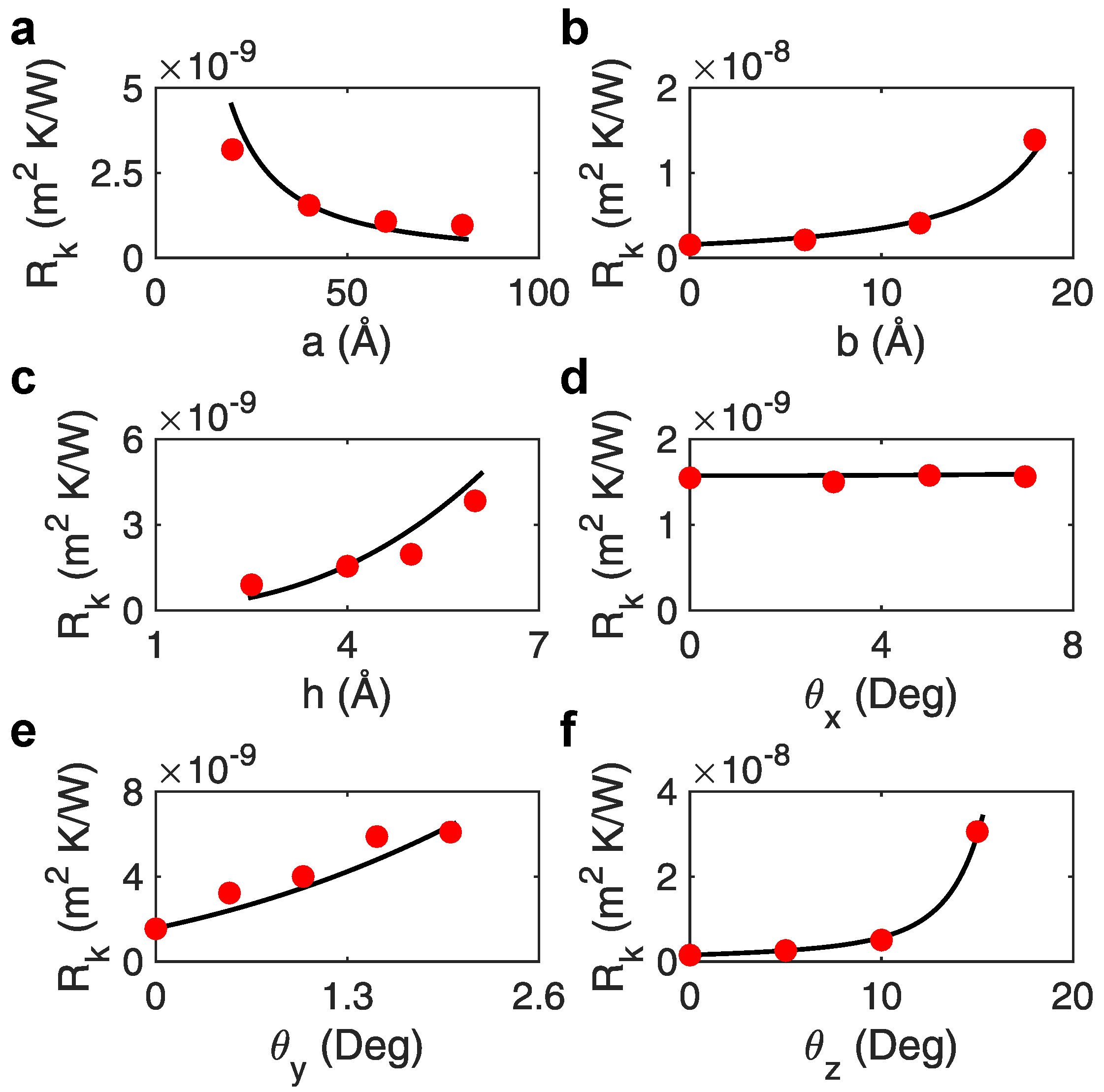
Firstly, the horizontal and vertical overlaps between the GNRs have been varied. The impact of horizontal overlap, a, is simulated in the range 20–80 Å, with b fixed at 0 Å, h at 4 Å and angular displacement set to = (0,0,0). As depicted in Figure 3a and previously reported [36], decreases with larger horizontal overlap following a power law, because this allows enhanced van der Waals interactions between GNRs and thus better phononic heat transfer [44]. A similar behaviour is observed for varying values of vertical overlap (b tested in the range 0–18 Å, with a fixed at 40 Å, h at 4 Å and = (0,0,0)), since less overlapping area (i.e., higher b) leads to a power increase of (see Figure 3b). The impact of interplanar spacing between the GNRs has been instead studied with h in the range 2.5–6 Å, while a is fixed at 40 Å, b at 0 Å and = (0,0,0). Since van der Waals interactions tend to drastically decrease with distance (12-6 Lennard-Jones potential), the results in Figure 3c confirm a power-law-like increase of with h, in good accordance with previous works [36].
Secondly, the effect of angular displacement between graphene nanoribbons on has been studied around the x, y and z axes (see Figure 1b). The central GNR is rotated around the x axis with ranging in the interval 0–7, while the other geometrical parameters are kept constant ( Å, Å, Å, ). The results in Figure 3d show no significant variation of with . This could be due to the fact that, in the reference system considered, rotations around the x axis cause half of the central GNR to approach the lateral GNRs (i.e., increased heat transfer), and the other half to move away from it (i.e., reduced heat transfer). These competing phenomena may balance each other, therefore leading to an approximately constant with . Conversely, rotations around the y axis ( from to ; Å, Å, Å, ) induce larger (Figure 3e), because of the increasing average distance between GNRs and thus the reduced phononic heat transfer through van der Waals interactions. Finally, the central sheet is rotated around the z axis in the 0–45 range, while keeping the other geometrical parameters fixed as Å, Å, Å and . The results in Figure 3f show a strong increase of with , because of the progressively reduced overlapping area between the GNRs and thus phononic heat transfer at the interface.
Inspired by the approach typically employed for classic heat transfer phenomena, the main geometrical parameters influencing the at the GNR-GNR interface have been grouped into meaningful dimensionless quantities. In particular, we suggest the following set of possible dimensionless quantities: the normalized interfacial thermal resistance
namely the ratio between interfacial (GNR-GNR) and internal (single GNR) thermal resistance; the normalized projected overlap
that is the ratio between the projected overlapping area and the GNR size; the normalized average interplanar spacing
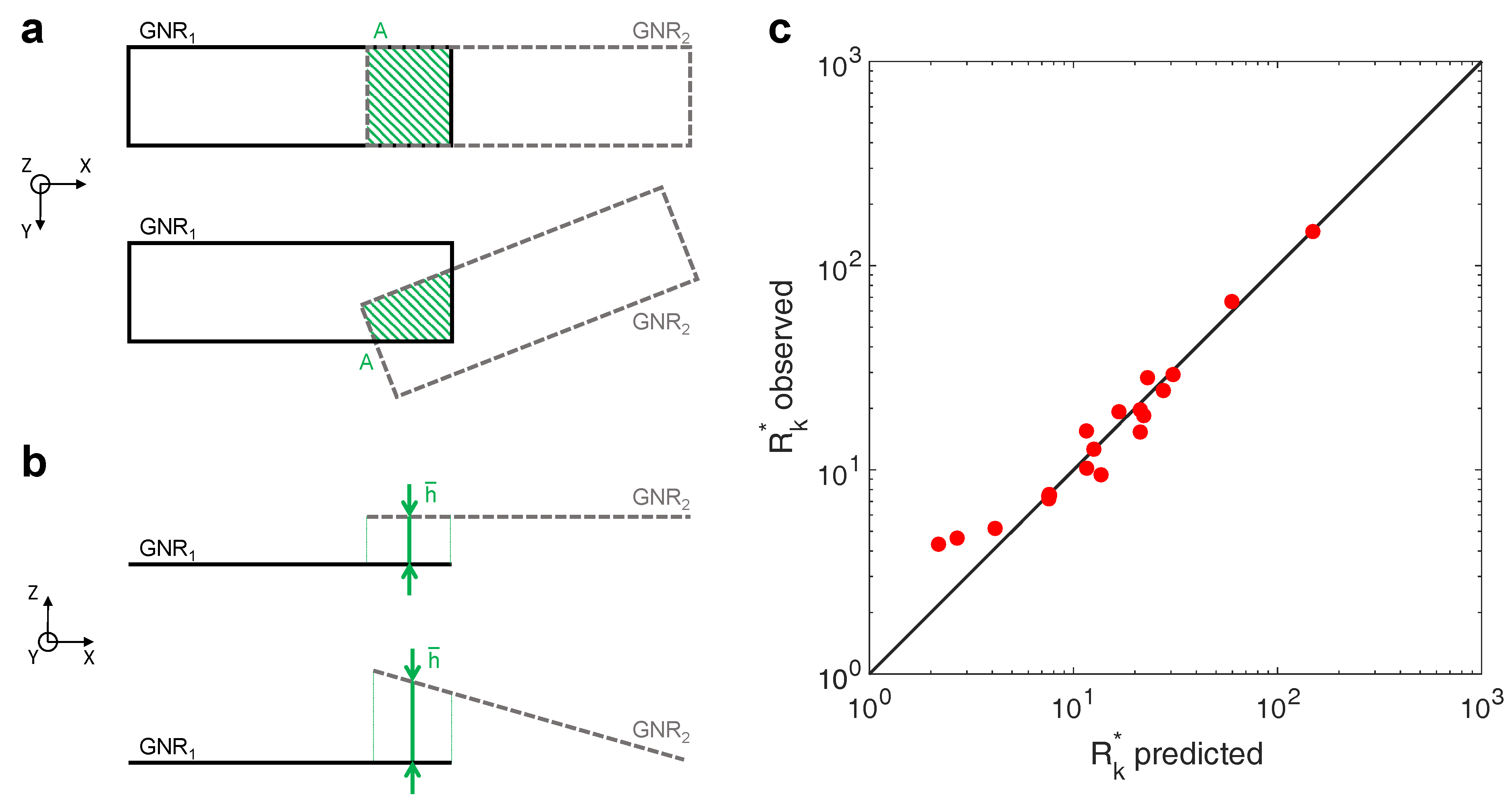
namely the ratio between the average interplanar spacing between the adjacent GNRs and the distance of their closest possible approach at equilibrium conditions (van der Waals radius). Because of their definitions, and . In the simulated setups, W/m·K and Å [36]. In the reference system considered, A is estimated by projecting along the z axis the overlapping area between two adjacent GNRs (see, for example, the green surfaces in Figure 4a). The average interplanar spacing, instead, is computed by averaging the interplanar spacing (h) between two adjacent GNRs in the overlapping area (see, for example, the green lines in Figure 4b). The complete list of , and values for the simulation setups considered is reported in Table A1.
To achieve a quantitative correlation between and the dimensionless quantities suggested, the Artificial Intelligence-powered modelling engine by Eureqa software [50,51] has been employed. In detail, Eureqa employs genetic algorithms to identify the mathematical equation f that best match a set of data, that is in this case. Similarly to the typical empirical expressions adopted for heat transfer, only basic formula building-blocks (i.e., constant, multiplication, division, power) have been considered for the Eureqa fitting. As a result, the simulation results in Table A1 (configurations N. 1–20) have been found to be best fitted (R2 = 0.99, see Figure 4b) by the following expression:
being , and . Coherently with the simulation evidence depicted in Figure 3, the interfacial thermal resistance increases with the average interplanar spacing, while larger overlapping areas lead to enhanced heat transfer between adjacent GNRs (i.e., lower ). Notably, is more sensitive to variations compared to ones.
The full list of values obtained by Molecular Dynamics (MD) simulations (red dots) and predicted by Equation (5) (black lines) is reported graphically in Figure 3 and numerically in Table A1. It is worth noting that Equation (5) is valid for . However, configurations characterized by no overlapping area () typically show m2K/W and thus the GNRs can be considered as thermally insulated from each other (see, for instance, the configurations N. 21 and 22 in Table A1): this would eventually avoid the creation of a percolating network through the polymer matrix in which they are included.
4. Discussion
If GNRs are employed as fillers to improve the properties of polymeric matrix, the estimation of at the interface between the GNRs is helpful to compute the effective thermal conductivity () of the resulting composite. Considering, for example, the modified Maxwell-Garnett effective medium approximation by Shahil and Balandin [52], the can be computed as
where: and are the thermal conductivities of filler particles and polymeric matrix; is the volume fraction of fillers; is the interfacial thermal resistance at the filler-matrix interface; H is the thickness of fillers. Since graphene fillers tend to disperse non-homogeneously within the polymeric matrix and to create aggregates or networks with different sizes [53,54], should be computed for the graphene aggregates rather than for the graphene nanoparticles alone. For instance, considering the setup in Figure 1a as a representative aggregate of GNRs, the equivalent of the network can be computed by a one-dimensional approximation of heat conduction along the main axis (x, in this case), that is
where a series of lumped thermal resistances due to the N GNRs and M GNR-GNR interfaces is taken into account. In Equation (7), the following notations are adopted: , overall length of the fillers network along x axis; and , respectively the length and thermal conductivity of the i-th GNR filler along x axis; , the interfacial thermal resistance at the j-th filler-filler interface, which could be readily computed by Equation (5) given the relative orientations of GNRs. Clearly, more accurate estimates of could be achieved by three-dimensional models of heat conduction through the aggregate, for example employing effective medium approximations [55], shape factors [56], mesoscopic [42] or continuum [57] simulation models, which would anyway require an accurate estimation of .
5. Conclusions
In this study, the effect of relative orientation of isolated adjacent graphene nanoribbons on the thermal resistance at their interface has been systematically studied by reverse non-equilibrium molecular dynamics. A simulation setup consisting of three GNRs was considered as a minimal and relevant building block of more complex networks of nanofillers, such as those that can be found in polymer nanocomposites above the percolation threshold. The analysis included different geometrical characteristics of the network, such as the GNR-GNR overlap along the x, y, z directions and rotation around the x, y, z axes. Simulation results allowed an empirical and comprehensive correlation between the aforementioned geometrical parameters and to be determined for thermally percolating networks of GNRs, namely for m2K/W. This correlation was found to accurately predict the simulated interfacial thermal resistance between contiguous GNRs, at least in the geometrical ranges considered. The proposed correlation could be utilized for the bottom-up prediction and optimization of the effective thermal transmittance of graphene nanofiller networks [58]. Future studies should focus on assessing the possible effect of irregular GNR shapes on the at the filler-filler interface [59], and determining similar correlations for the at the filler-matrix interface taking into account the effect of matrix and filler functionalizations. In a broader context, this study may facilitate the design of carbon reinforced polymer nanocomposites with adjustable/enhanced thermal properties.
Author Contributions
S.M.N. and M.B.B. carried out simulations. M.F. and R.S. analysed and interpreted simulation results. M.F. conceived and supervised the study. All authors contributed to write the manuscript and approved it in the final form.
Funding
This research has received funding via the MODCOMP project from the European Union’s Horizon 2020 research and innovation programme under Grant Agreement N. 685844. M.F. acknowledges partial financial support from the Politecnico di Torino through the RTDa Starting Grant (grant number 56_RIL16FAM01).
Acknowledgments
Computational resources were provided by HPC@POLITO (http://www.hpc.polito.it). We thank Eliodoro Chiavazzo and Pietro Asinari for useful discussion on data interpretation.
Conflicts of Interest
The authors declare no conflict of interest.
Abbreviations
The following abbreviations are used in this manuscript:
| GNRs | Graphene Nanoribbons |
| PNCs | Polymer Nanocomposites |
| MD | Molecular Dynamics |
| AIREBO | Adaptive Intermolecular Reactive Empirical Bond Order |
| LAMMPS | Large-scale Atomic/Molecular Massively Parallel Simulator |
Appendix A

Table A1.
List of Molecular Dynamics (MD) and fitting (Equation (5)) results of at the GNR-GNR interface, as illustrated in the setup in Figure 1. Notice that the correlation in Equation (5) has been fitted against the results of configurations N. 1–20; whereas, configurations N. 21 and 22 highlight the range of validity of the correlation, that is and m2K/W.
| N. | a (Å) | b (Å) | h (Å) | , MD (×10−9 m2K/W) | , MD | , Fitting | |||||
|---|---|---|---|---|---|---|---|---|---|---|---|
| 1 | 20 | 0 | 4 | 0 | 0 | 0 | 3.19 | 0.10000 | 1.17647 | 15.32 | 21.23 |
| 2 | 40 | 0 | 4 | 0 | 0 | 0 | 1.55 | 0.20000 | 1.17647 | 7.44 | 7.55 |
| 3 | 60 | 0 | 4 | 0 | 0 | 0 | 1.08 | 0.30000 | 1.17647 | 5.16 | 4.13 |
| 4 | 80 | 0 | 4 | 0 | 0 | 0 | 0.97 | 0.40000 | 1.17647 | 4.63 | 2.69 |
| 5 | 40 | 6 | 4 | 0 | 0 | 0 | 2.12 | 0.15000 | 1.17647 | 10.18 | 11.60 |
| 6 | 40 | 12 | 4 | 0 | 0 | 0 | 4.10 | 0.10000 | 1.17647 | 19.67 | 21.23 |
| 7 | 40 | 18 | 4 | 0 | 0 | 0 | 13.90 | 0.05000 | 1.17647 | 66.72 | 59.68 |
| 8 | 40 | 0 | 2.5 | 0 | 0 | 0 | 0.90 | 0.20000 | 0.73529 | 4.32 | 2.18 |
| 9 | 40 | 0 | 5 | 0 | 0 | 0 | 1.97 | 0.20000 | 1.47058 | 9.46 | 13.63 |
| 10 | 40 | 0 | 6 | 0 | 0 | 0 | 3.84 | 0.20000 | 1.76470 | 18.44 | 22.08 |
| 11 | 40 | 0 | 4 | 3 | 0 | 0 | 1.50 | 0.19972 | 1.17647 | 7.21 | 7.57 |
| 12 | 40 | 0 | 4 | 5 | 0 | 0 | 1.58 | 0.19923 | 1.17647 | 7.57 | 7.60 |
| 13 | 40 | 0 | 4 | 7 | 0 | 0 | 1.56 | 0.19850 | 1.17647 | 7.50 | 7.64 |
| 14 | 40 | 0 | 4 | 0 | 0.5 | 0 | 3.23 | 0.19998 | 1.38180 | 15.50 | 11.56 |
| 15 | 40 | 0 | 4 | 0 | 1 | 0 | 4.01 | 0.19992 | 1.58714 | 19.26 | 16.69 |
| 16 | 40 | 0 | 4 | 0 | 1.5 | 0 | 5.89 | 0.19982 | 1.79248 | 28.27 | 23.04 |
| 17 | 40 | 0 | 4 | 0 | 2 | 0 | 6.10 | 0.19969 | 1.99782 | 29.28 | 30.73 |
| 18 | 40 | 0 | 4 | 0 | 0 | 5 | 2.63 | 0.14206 | 1.17647 | 12.61 | 12.58 |
| 19 | 40 | 0 | 4 | 0 | 0 | 10 | 5.09 | 0.08399 | 1.17647 | 24.45 | 27.54 |
| 20 | 40 | 0 | 4 | 0 | 0 | 15 | 30.61 | 0.02708 | 1.17647 | 146.94 | 148.90 |
| 21 | 40 | 0 | 4 | 0 | 0 | 30 | 112.00 | 0.00000 | 1.17647 | 537.60 | - |
| 22 | 40 | 0 | 4 | 0 | 0 | 45 | 119.99 | 0.00000 | 1.17647 | 575.96 | - |
References
- Marconnet, A.M.; Panzer, M.A.; Goodson, K.E. Thermal conduction phenomena in carbon nanotubes and related nanostructured materials. Rev. Mod. Phys. 2013, 85, 1295. [Google Scholar] [CrossRef]
- Colla, L.; Fedele, L.; Mancin, S.; Danza, L.; Manca, O. Nano-PCMs for enhanced energy storage and passive cooling applications. Appl. Therm. Eng. 2017, 110, 584–589. [Google Scholar] [CrossRef]
- Rabczuk, T.; Azadi Kakavand, M.R.; Palanivel Uma, R.; Hossein Nezhad Shirazi, A.; Makaremi, M. Thermal Conductance along Hexagonal Boron Nitride and Graphene Grain Boundaries. Energies 2018, 11, 1553. [Google Scholar] [CrossRef]
- Sheikholeslami, M.; Mehryan, S.; Shafee, A.; Sheremet, M.A. Variable magnetic forces impact on magnetizable hybrid nanofluid heat transfer through a circular cavity. J. Mol. Liq. 2019, 277, 388–396. [Google Scholar] [CrossRef]
- Du, Y.; Li, H.; Jia, X.; Dou, Y.; Xu, J.; Eklund, P. Preparation and Thermoelectric Properties of Graphite/poly (3,4-ethyenedioxythiophene) Nanocomposites. Energies 2018, 11, 2849. [Google Scholar] [CrossRef]
- Zhang, X.; Wen, H.; Chen, X.; Wu, Y.; Xiao, S. Study on the Thermal and Dielectric Properties of SrTiO3/Epoxy Nanocomposites. Energies 2017, 10, 692. [Google Scholar] [CrossRef]
- Sangermano, M.; Calvara, L.; Chiavazzo, E.; Ventola, L.; Asinari, P.; Mittal, V.; Rizzoli, R.; Ortolani, L.; Morandi, V. Enhancement of electrical and thermal conductivity of Su-8 photocrosslinked coatings containing graphene. Prog. Org. Coat. 2015, 86, 143–146. [Google Scholar] [CrossRef]
- Kawai, S.; Benassi, A.; Gnecco, E.; Söde, H.; Pawlak, R.; Feng, X.; Müllen, K.; Passerone, D.; Pignedoli, C.A.; Ruffieux, P.; et al. Superlubricity of graphene nanoribbons on gold surfaces. Science 2016, 351, 957–961. [Google Scholar] [CrossRef] [PubMed] [Green Version]
- Crisafulli, A.; Khodayari, A.; Mohammadnejad, S.; Fasano, M. Sliding Dynamics of Parallel Graphene Sheets: Effect of Geometry and Van Der Waals Interactions on Nano-Spring Behavior. Crystals 2018, 8, 149. [Google Scholar] [CrossRef]
- Bu, H.; Chen, Y.; Zou, M.; Yi, H.; Bi, K.; Ni, Z. Atomistic simulations of mechanical properties of graphene nanoribbons. Phys. Lett. A 2009, 373, 3359–3362. [Google Scholar] [CrossRef]
- Pereira, L.F.C.; Mortazavi, B.; Makaremi, M.; Rabczuk, T. Anisotropic thermal conductivity and mechanical properties of phagraphene: A molecular dynamics study. RSC Adv. 2016, 6, 57773–57779. [Google Scholar] [CrossRef]
- Sáenz Ezquerro, C.; Laspalas, M.; Chiminelli, A.; Serrano, F.; Valero, C. Interface Characterization of Epoxy Resin Nanocomposites: A Molecular Dynamics Approach. Fibers 2018, 6, 54. [Google Scholar] [CrossRef]
- Serrano, E.; Rus, G.; Garcia-Martinez, J. Nanotechnology for sustainable energy. Renew. Sustain. Energy Rev. 2009, 13, 2373–2384. [Google Scholar] [CrossRef]
- Trompeta, A.F.A.; Koumoulos, E.P.; Stavropoulos, S.G.; Velmachos, T.G.; Psarras, G.C.; Charitidis, C.A. Assessing the Critical Multifunctionality Threshold for Optimal Electrical, Thermal, and Nanomechanical Properties of Carbon Nanotubes/Epoxy Nanocomposites for Aerospace Applications. Aerospace 2019, 6, 7. [Google Scholar] [CrossRef]
- Cheng, Z.; Chai, R.; Ma, P.; Dai, Y.; Kang, X.; Lian, H.; Hou, Z.; Li, C.; Lin, J. Multiwalled carbon nanotubes and NaYF4: Yb3+/Er3+ Nanoparticle-Doped Bilayer hydrogel for concurrent nir-triggered drug release and up-conversion luminescence tagging. Langmuir 2013, 29, 9573–9580. [Google Scholar] [CrossRef] [PubMed]
- He, S.; Chen, L.; Xie, C.; Hu, H.; Chen, S.; Hanif, M.; Hou, H. Supercapacitors based on 3D network of activated carbon nanowhiskers wrapped-on graphitized electrospun nanofibers. J. Power Sources 2013, 243, 880–886. [Google Scholar] [CrossRef]
- Mortazavi, B.; Makaremi, M.; Shahrokhi, M.; Fan, Z.; Rabczuk, T. N-graphdiyne two-dimensional nanomaterials: Semiconductors with low thermal conductivity and high stretchability. Carbon 2018, 137, 57–67. [Google Scholar] [CrossRef]
- Pandey, G.; Thostenson, E.T. Carbon nanotube-based multifunctional polymer nanocomposites. Polym. Rev. 2012, 52, 355–416. [Google Scholar] [CrossRef]
- Shen, D.; Shi, S.; Xu, T. Effects of two-dimensional programming on microstructures and thermal properties of shape memory polymer-based composites. J. Appl. Polym. Sci. 2017, 134, 45480. [Google Scholar] [CrossRef]
- Speight, J.G. Lange’s Handbook of Chemistry; McGraw-Hill: New York, NY, USA, 2005; Volume 1. [Google Scholar]
- Han, Z.; Fina, A. Thermal conductivity of carbon nanotubes and their polymer nanocomposites: A review. Prog. Polym. Sci. 2011, 36, 914–944. [Google Scholar] [CrossRef] [Green Version]
- Pan, C.N.; Chen, X.K.; Tang, L.M.; Chen, K.Q. Orientation dependent thermal conductivity in graphyne nanoribbons. Phys. E Low-Dimens. Syst. Nanostruct. 2014, 64, 129–133. [Google Scholar] [CrossRef]
- Gojny, F.H.; Wichmann, M.H.; Fiedler, B.; Kinloch, I.A.; Bauhofer, W.; Windle, A.H.; Schulte, K. Evaluation and identification of electrical and thermal conduction mechanisms in carbon nanotube/epoxy composites. Polymer 2006, 47, 2036–2045. [Google Scholar] [CrossRef]
- Moisala, A.; Li, Q.; Kinloch, I.; Windle, A. Thermal and electrical conductivity of single-and multi-walled carbon nanotube-epoxy composites. Compos. Sci. Technol. 2006, 66, 1285–1288. [Google Scholar] [CrossRef]
- Bryning, M.; Milkie, D.; Islam, M.; Kikkawa, J.; Yodh, A. Thermal conductivity and interfacial resistance in single-wall carbon nanotube epoxy composites. Appl. Phys. Lett. 2005, 87, 161909. [Google Scholar] [CrossRef]
- Huxtable, S.T.; Cahill, D.G.; Shenogin, S.; Xue, L.; Ozisik, R.; Barone, P.; Usrey, M.; Strano, M.S.; Siddons, G.; Shim, M.; et al. Interfacial heat flow in carbon nanotube suspensions. Nat. Mater. 2003, 2, 731. [Google Scholar] [CrossRef] [PubMed]
- Hao, F.; Fang, D.; Xu, Z. Mechanical and thermal transport properties of graphene with defects. Appl. Phys. Lett. 2011, 99, 041901. [Google Scholar] [CrossRef]
- Kipper, A.C.; da Silva, L.B. Non equilibrium molecular dynamics simulation study of thermal conductivity in doped graphene nanoribbons. Phys. B Condens. Matter 2019, 556, 1–5. [Google Scholar] [CrossRef]
- Mortazavi, B.; Benzerara, O.; Meyer, H.; Bardon, J.; Ahzi, S. Combined molecular dynamics-finite element multiscale modeling of thermal conduction in graphene epoxy nanocomposites. Carbon 2013, 60, 356–365. [Google Scholar] [CrossRef]
- Gujrati, P.D.; Leonov, A.I. Modeling and Simulation in Polymers; John Wiley & Sons: Weinheim, Germany, 2010. [Google Scholar]
- Bui, K.; Duong, H.M.; Striolo, A.; Papavassiliou, D.V. Effective Heat Transfer Properties of Graphene Sheet Nanocomposites and Comparison to Carbon Nanotube Nanocomposites. J. Phys. Chem. C 2011, 115, 3872–3880. [Google Scholar] [CrossRef]
- Tascini, A.S.; Armstrong, J.; Chiavazzo, E.; Fasano, M.; Asinari, P.; Bresme, F. Thermal transport across nanoparticle–fluid interfaces: The interplay of interfacial curvature and nanoparticle–fluid interactions. Phys. Chem. Chem. Phys. 2017, 19, 3244–3253. [Google Scholar] [CrossRef] [PubMed]
- Fasano, M.; Bigdeli, M.B. Bottom up approach toward prediction of effective thermophysical properties of carbon-based nanofluids. Heat Transf. Eng. 2018, 39, 1690–1701. [Google Scholar] [CrossRef]
- Khodayari, A.; Fasano, M.; Bigdeli, M.B.; Mohammadnejad, S.; Chiavazzo, E.; Asinari, P. Effect of interfacial thermal resistance and nanolayer on estimates of effective thermal conductivity of nanofluids. Case Stud. Therm. Eng. 2018, 12, 454–461. [Google Scholar] [CrossRef]
- Bernal, M.M.; Di Pierro, A.; Novara, C.; Giorgis, F.; Mortazavi, B.; Saracco, G.; Fina, A. Edge-Grafted Molecular Junctions between Graphene Nanoplatelets: Applied Chemistry to Enhance Heat Transfer in Nanomaterials. Adv. Funct. Mater. 2018, 28, 1706954. [Google Scholar] [CrossRef] [Green Version]
- Bigdeli, M.B.; Fasano, M. Thermal transmittance in graphene based networks for polymer matrix composites. Int. J. Therm. Sci. 2017, 117, 98–105. [Google Scholar] [CrossRef]
- Varshney, V.; Roy, A.K.; Michalak, T.J.; Lee, J.; Farmer, B.L. Effect of curing and functionalization on the interface thermal conductance in carbon nanotube–epoxy composites. JOM 2013, 65, 140–146. [Google Scholar] [CrossRef]
- Wang, Y.; Zhan, H.; Xiang, Y.; Yang, C.; Wang, C.M.; Zhang, Y. Effect of covalent functionalization on thermal transport across graphene–polymer interfaces. J. Phys. Chem. C 2015, 119, 12731–12738. [Google Scholar] [CrossRef]
- Zabihi, Z.; Araghi, H. Effect of functional groups on thermal conductivity of graphene/paraffin nanocomposite. Phys. Lett. A 2016, 380, 3828–3831. [Google Scholar] [CrossRef]
- Fina, A.; Colonna, S.; Maddalena, L.; Tortello, M.; Monticelli, O. Facile and Low Environmental Impact Approach to Prepare Thermally Conductive Nanocomposites Based on Polylactide and Graphite Nanoplatelets. ACS Sustain. Chem. Eng. 2018, 6, 14340–14347. [Google Scholar] [CrossRef] [PubMed]
- Shenogin, S.; Bodapati, A.; Xue, L.; Ozisik, R.; Keblinski, P. Effect of chemical functionalization on thermal transport of carbon nanotube composites. Appl. Phys. Lett. 2004, 85, 2229–2231. [Google Scholar] [CrossRef]
- Chiavazzo, E.; Asinari, P. Reconstruction and modeling of 3D percolation networks of carbon fillers in a polymer matrix. Int. J. Therm. Sci. 2010, 49, 2272–2281. [Google Scholar] [CrossRef] [Green Version]
- Shtein, M.; Nadiv, R.; Buzaglo, M.; Kahil, K.; Regev, O. Thermally conductive graphene-polymer composites: Size, percolation, and synergy effects. Chem. Mater. 2015, 27, 2100–2106. [Google Scholar] [CrossRef]
- Fasano, M.; Bigdeli, M.B.; Sereshk, M.R.V.; Chiavazzo, E.; Asinari, P. Thermal transmittance of carbon nanotube networks: Guidelines for novel thermal storage systems and polymeric material of thermal interest. Renew. Sustain. Energy Rev. 2015, 41, 1028–1036. [Google Scholar] [CrossRef]
- Stuart, S.J.; Tutein, A.B.; Harrison, J.A. A reactive potential for hydrocarbons with intermolecular interactions. J. Chem. Phys. 2000, 112, 6472–6486. [Google Scholar] [CrossRef]
- Plimpton, S. Fast parallel algorithms for short-range molecular dynamics. J. Comput. Phys. 1995, 117, 1–19. [Google Scholar] [CrossRef]
- Müller-Plathe, F. A simple nonequilibrium molecular dynamics method for calculating the thermal conductivity. J. Chem. Phys. 1997, 106, 6082–6085. [Google Scholar] [CrossRef]
- Sledzinska, M.; Quey, R.; Mortazavi, B.; Graczykowski, B.; Placidi, M.; Saleta Reig, D.; Navarro-Urrios, D.; Alzina, F.; Colombo, L.; Roche, S.; et al. Record Low Thermal Conductivity of Polycrystalline MoS2 Films: Tuning the Thermal Conductivity by Grain Orientation. ACS Appl. Mater. Interfaces 2017, 9, 37905–37911. [Google Scholar] [CrossRef] [PubMed]
- Hamby, D. A review of techniques for parameter sensitivity analysis of environmental models. Environ. Monit. Assess. 1994, 32, 135–154. [Google Scholar] [CrossRef] [PubMed] [Green Version]
- Schmidt, M.; Lipson, H. Distilling free-form natural laws from experimental data. Science 2009, 324, 81–85. [Google Scholar] [CrossRef] [PubMed]
- Schmidt, M.; Lipson, H. Eureqa (Version 0.98 Beta) [Software], Nutonian: Somerville, MA, USA, 2013.
- Shahil, K.M.; Balandin, A.A. Graphene–multilayer graphene nanocomposites as highly efficient thermal interface materials. Nano Lett. 2012, 12, 861–867. [Google Scholar] [CrossRef] [PubMed]
- Tarani, E.; Papageorgiou, D.; Valles, C.; Wurm, A.; Terzopoulou, Z.; Bikiaris, D.; Schick, C.; Chrissafis, K.; Vourlias, G. Insights into crystallization and melting of high density polyethylene/graphene nanocomposites studied by fast scanning calorimetry. Polym. Test. 2018, 67, 349–358. [Google Scholar] [CrossRef]
- Roussou, R.E.; Karatasos, K. Graphene/poly (ethylene glycol) nanocomposites as studied by molecular dynamics simulations. Mater. Des. 2016, 97, 163–174. [Google Scholar] [CrossRef]
- Cardellini, A.; Fasano, M.; Bigdeli, M.B.; Chiavazzo, E.; Asinari, P. Thermal transport phenomena in nanoparticle suspensions. J. Phys. Condens. Matter 2016, 28, 483003. [Google Scholar] [CrossRef] [PubMed] [Green Version]
- Rohsenow, W.M.; Hartnett, J.P.; Cho, Y.I. Handbook of Heat Transfer; McGraw-Hill: New York, NY, USA, 1998; Volume 3. [Google Scholar]
- Zhou, H.; Wang, H.; Du, X.; Zhang, Y.; Zhou, H.; Yuan, H.; Liu, H.Y.; Mai, Y.W. Facile fabrication of large 3D graphene filler modified epoxy composites with improved thermal conduction and tribological performance. Carbon 2018, 139, 1168–1177. [Google Scholar] [CrossRef]
- Rafiee, M.; Nitzsche, F.; Laliberte, J.; Hind, S.; Robitaille, F.; Labrosse, M. Thermal properties of doubly reinforced fiberglass/epoxy composites with graphene nanoplatelets, graphene oxide and reduced-graphene oxide. Compos. Part B Eng. 2019, 164, 1–9. [Google Scholar] [CrossRef]
- Annett, J.; Cross, G.L. Self-assembly of graphene ribbons by spontaneous self-tearing and peeling from a substrate. Nature 2016, 535, 271. [Google Scholar] [CrossRef] [PubMed]
Figure 1.
Networks of graphene nanoribbons (GNRs) studied by reverse non-equilibrium molecular dynamics simulations. (a) Configuration adopted to investigate the effect of horizontal overlap (a, along x axis), vertical overlap (b, along y axis) and interplanar spacing (h, along z axis) on the between GNRs (W width, L length). In the inset, the definition of b is highlighted. Muller-Plathe’s algorithm is used to assure a constant heat flux from the region of the setup with higher temperature to the lower ones. (b) Configurations adopted to study the effect of angular displacement () on the average between GNRs. The tested configurations have been chosen according to the one-at-a-time sensitivity approach [49].

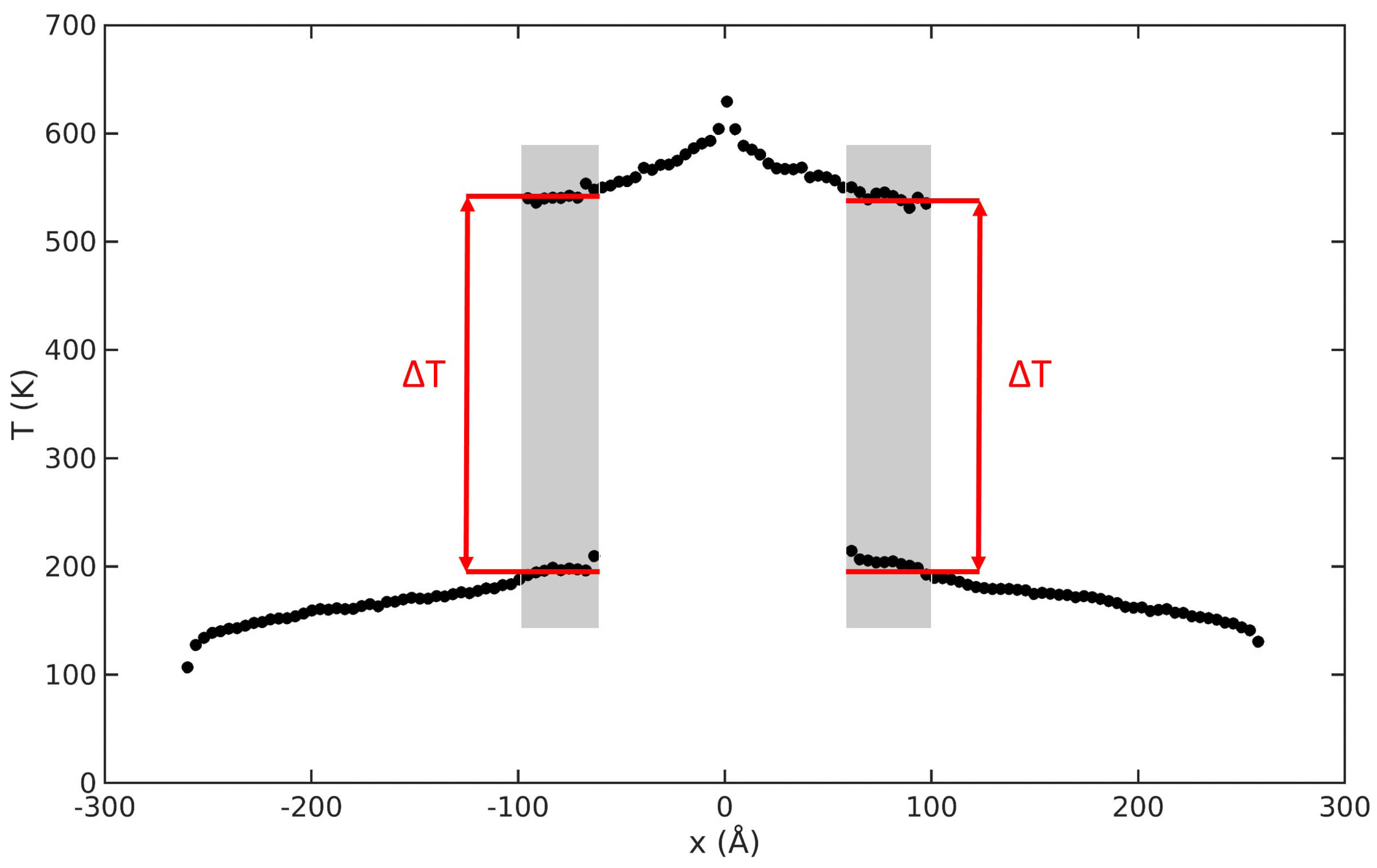
Figure 2.
Steady state temperature profile through a representative network of 3 GNRs, as achieved in the reverse non-equilibrium molecular dynamics simulation. The average temperature jump () at the interface between overlapping GNRs (grey rectangles) is employed in Equation (1) to compute .
Figure 2.
Steady state temperature profile through a representative network of 3 GNRs, as achieved in the reverse non-equilibrium molecular dynamics simulation. The average temperature jump () at the interface between overlapping GNRs (grey rectangles) is employed in Equation (1) to compute .

Figure 3.
Interfacial thermal resistance () at the GNR-GNR interface, as a function of (a) horizontal overlap a, (b) vertical overlap b, (c) interplanar spacing h, (d) angular displacement around x axis , (e) y axis , and (f) z axis between adjacent GNRs. Molecular dynamics results (red dots) are fitted by the correlation reported in Equation (5) (black curves). Error bars are computed from time-block analysis of steady state trajectories and, when not visible, are smaller than symbol size.

Figure 4.
(a) Examples of projected overlapping area (A, green texture) between GNR1 (solid black line) and GNR2 (dashed grey line) nanoribbons. (b) Examples of average interplanar spacing (, green line) between GNR1 (solid black line) and GNR2 (dashed grey line) nanoribbons. (c) Reduced value of Kapitza resistance at the GNR-GNR interface (): predicted values from the best-fitted Equation (5) vs. observed values by Molecular Dynamics (MD) simulations.
© 2019 by the authors. Licensee MDPI, Basel, Switzerland. This article is an open access article distributed under the terms and conditions of the Creative Commons Attribution (CC BY) license (http://creativecommons.org/licenses/by/4.0/).
Share and Cite
MDPI and ACS Style
Mohammad Nejad, S.; Bozorg Bigdeli, M.; Srivastava, R.; Fasano, M. Heat Transfer at the Interface of Graphene Nanoribbons with Different Relative Orientations and Gaps. Energies 2019, 12, 796. https://doi.org/10.3390/en12050796
AMA Style
Mohammad Nejad S, Bozorg Bigdeli M, Srivastava R, Fasano M. Heat Transfer at the Interface of Graphene Nanoribbons with Different Relative Orientations and Gaps. Energies. 2019; 12(5):796. https://doi.org/10.3390/en12050796
Chicago/Turabian StyleMohammad Nejad, Shahin, Masoud Bozorg Bigdeli, Rajat Srivastava, and Matteo Fasano. 2019. "Heat Transfer at the Interface of Graphene Nanoribbons with Different Relative Orientations and Gaps" Energies 12, no. 5: 796. https://doi.org/10.3390/en12050796
Note that from the first issue of 2016, this journal uses article numbers instead of page numbers. See further details here.