Article

Design and Analysis of Surface-Mounted PM Vernier Machines Considering Harmonic Characteristics of Winding MMF

Mechatronics System Research Laboratory, Electrical Engineering Department, Dong-A University, Busan 52121, Korea
*
Author to whom correspondence should be addressed.
Energies 2019, 12(5), 897; https://doi.org/10.3390/en12050897
Submission received: 12 February 2019 / Revised: 3 March 2019 / Accepted: 5 March 2019 / Published: 7 March 2019
(This article belongs to the Section F: Electrical Engineering)

Abstract

:
This paper proposes a design method for the flux modulation poles (FMPs) formed on the stator of surface-mounted permanent magnet vernier machines (SPMVM) considering the winding configurations. In three types of the SPMVM with the different winding configurations, the FMP shapes to maximize the output torque are optimized by employing the analytical equations for the magneto-motive force (MMF) due to the windings, permeance, and flux density in the air-gap. Then, the validity of the optimal shapes for the FMPs is verified by the finite element analysis. It is found that the optimal FMP shapes are designed differently in the three types of the SPMVM and increase the output torque by different ratios according to the winding configurations. In addition, the experimental results for the prototype show that the proposed method can optimally design the FMP shape by analyzing mathematically the effects of the winding configuration and the FMP shape on the output torque of the SPMVM.

1. Introduction

Surface-mounted permanent magnet vernier machines (SPMVM) have been considered as good candidates to meet the demand for high torque density in direct-driven systems [1,2] such as electric vehicles [3,4,5] and wind power generators [6,7,8]. In the SPMVM, the numbers of stator and rotor poles are different, but their magnetic fields are synchronized with each other by the magnetic gearing effects. Such magnetic coupling allows the SPMVM to achieve a larger torque density compared with the regular permanent magnet (PM) machines [9]. To utilize the desirable flux modulation, the SPMVM requires the stator structures with the salient-poles, i.e., flux modulation poles (FMPs) [10,11,12]. Because of the air-gap permeance of the FMPs, the magneto-motive force (MMF) of the stator windings is modulated into the air-gap flux density harmonic corresponding to the number of rotor pole-pairs. The resulting flux density harmonic can be defined as working harmonic that produces the output torque by synchronizing with the magnetic field of the rotor PMs. It means that the torque capacity depends on the working harmonic that is created by the magnetic interactions between the winding MMF harmonics and the permeance harmonics. In the previous studies, regardless of the winding configurations, the FMPs were designed at equal intervals, and the resulting permeance distribution consisted of only the spatial harmonics corresponding to multiples of the FMF numbers [11,12,13]. However, the output torque of the SPMVM can be improved by adjusting the FMP shape to change the harmonic components of the permeance that create the working harmonic by interacting with the winding MMF harmonics [14]. Hence, to maximize the output torque of the SPMVM, the FMPs shape of the SPMVM is necessary to be designed with consideration to the harmonic characteristics of the permeance and winding MMF.
This paper presents the design method for the FMP shape to maximize the output torque of the SPMVM while considering the harmonic characteristics of the winding MMF. To do so, the analytical equations for the winding MMF, permeance, and flux density distributions in the air-gap were derived by using the Fourier analysis method. Particularly, to consider the variations of the design variables for the FMP shape, the Fourier coefficients for the permeance were derived as the functions, including the design variables. Then, the amplitude of the working harmonic was formulated into an analytical equation that consisted of the design variables. Thus, in the analytical equation, the optimal set of the design variables for the FMP shape could be obtained by using the genetic algorithm on the condition for maximizing the working harmonic. For the three types of the SPMVM with different winding configurations, the FMP shapes were optimized using the proposed method. In addition, the effects of the optimal FMP shapes were verified by the finite element analysis (FEA) method and the experiment for the prototypes. The experimental results show that applying the optimal FMP shapes can improve the average torque up to 24.2%.

2. Air-Gap Magnetic Field by Armature Windings

2.1. Structures of the SPMVM

Figure 1 shows three types of the SPMVM with different winding configurations. The stators had 12 slots and 24 FMPs. However, the armature windings in Machines 1, 2, and 3 produced the magnetic fields of two, four, and five pole pairs, respectively. Based on the following rule for the SPMVM, the rotor pole pairs for Machines 1, 2, and 3 were set as 22, 20, and 19, respectively [13].
p r = N F M P p s
where, ps and NFMP are the numbers of the stator pole pairs and FMPs, respectively. For a fair comparison, the basic specifications for the machines were applied identically as follows. The outer diameter of the stator was 90 mm, the air-gap length was 0.55 mm, the thickness of the PMs was 2 mm, the core lamination was 25 mm, and the number of turns per phase was 52. Moreover, the core material was 35PN230, the residual flux density of the PM was 1.2 T, and the rated phase current was 10 A.

2.2. Winding MMF Distribution

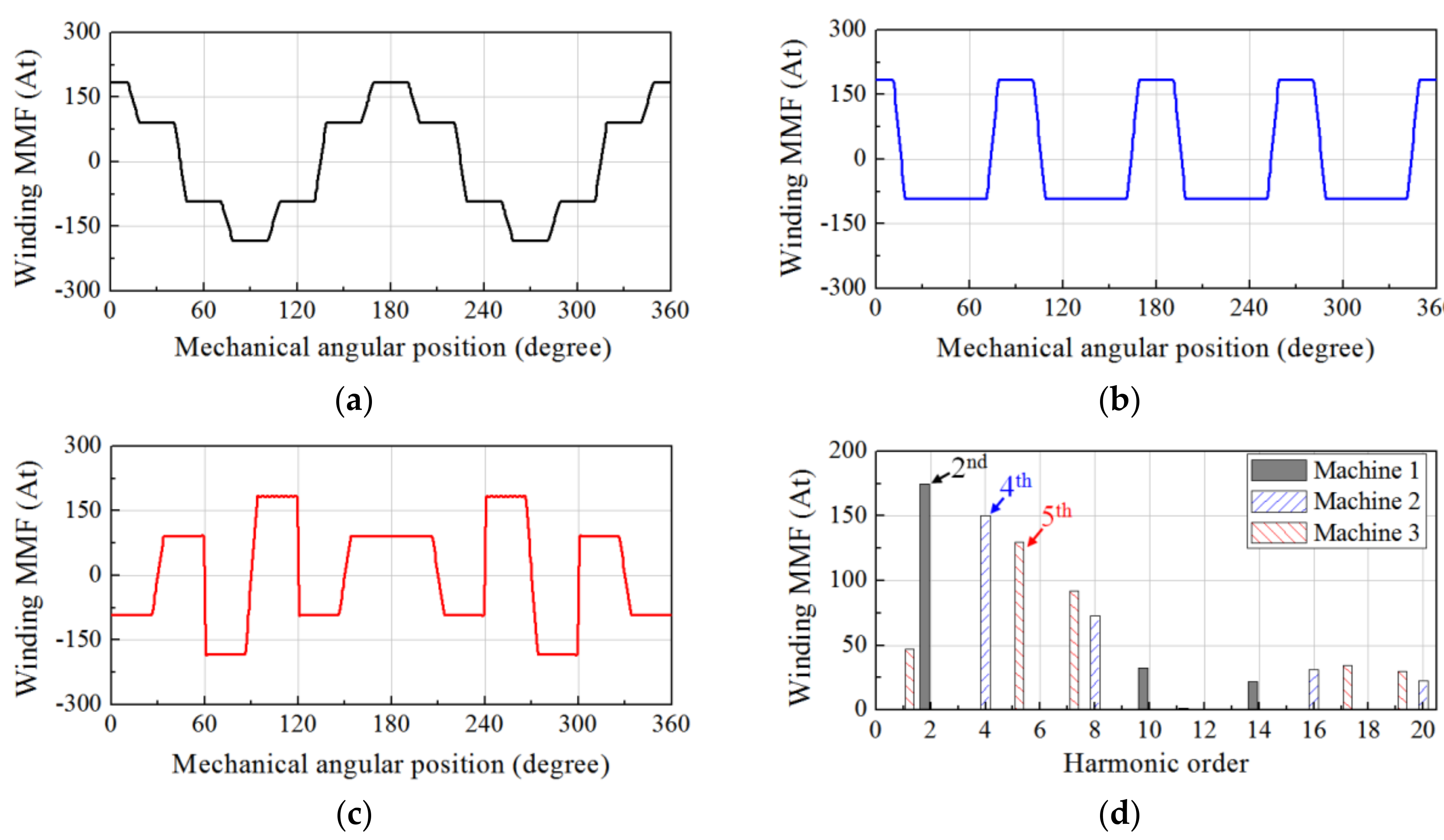
Figure 2 shows the winding MMF distributions for the machines. Based on the Fourier analysis method, the analytical equation for the winding MMF distribution is given as [15]:
F ( θ m , t ) = m = 1 , 4 , 7 , F m p cos ( m p θ m ω e t ) + m = 2 , 5 , 8 , F m p cos ( m p θ m + ω e t )
where p means the number of repeated waveforms in the mechanical MMF distribution, and its values for Machines 1, 2, and 3 were two, four, and one, respectively; θm and Fmp are the mechanical angular position and the Fourier coefficient for the winding MMF, respectively. Furthermore, the Fourier coefficient for each machine is given as:
  • For Machine 1,
    F m p = 6 N c I max m 2 p θ s o π sin m p θ s o 2 sin m π 6 + sin 5 m π 6
  • For Machine 2,
    F m p = 6 N c I max m 2 p θ s o π sin m p θ s o 2 sin m π 3
  • For Machine 3,
    F m p = 6 N c I max m 2 p θ s o π m p θ s o sin m π 3 + m p θ s o sin 2 m π 3 4 sin m π 2
    where θso, Nc, and Imax are the slot opening, the number of turns per coil, and the peak value of the phase current, respectively.

2.3. Permeance Distribution

Figure 3 shows the design variables for the FMP shape and the resulting air-gap permeance distribution. In addition, the distribution of the permeance in the air-gap is given as:
P ( θ m ) = P 0 + j = 1 , 2 , 3 , P j N s cos ( j N s θ m )
where Ns, P0, and PjNs are the number of slots, the direct current (DC) offset value of the permeance, and the Fourier coefficient for the permeance harmonic, respectively. Based on the Fourier analysis method and the permeance distribution, as shown in Figure 3, the DC offset value, P0, and Fourier coefficient PjNs could be derived as the functions, including the design variables θ1, θ2, and θso.
In the air-gap, the permeance per unit area was in inverse proportion to the length of the magnetic flux path l as the following [16]:
P ( θ m ) = μ 0 / l ( θ m )
In the regions directly below the FMPs, the permeance per unit area had a maximum value Pmax. Since the magnetic flux path in these regions was constant, Pmax could be calculated accurately by (7). However, the flux path in the slot opening and auxiliary slot was changed, along with the circumferential direction, because of the fringing flux. Consequently, the permeance in the centers of θ1 and θso had the local minimum values Pθ1 and Pso, respectively. Furthermore, Pθ1 and Pso were changed according to θ1 and θso, respectively. To improve the accuracy of the permeance function in (6), the local minimum values were calculated by using the FEA method, and then their variations were interpolated by using the least-square method. Figure 4 shows the variations of Pθ1 and Pso according to θ1 and θso obtained by the FEA and the following interpolation functions.
P θ 1 = 5.22 14.41 × θ 1 + 29.02 × θ 1 2 × 10 4
P s o = 5.16 12.04 × θ s o + 5.13 × θ s o 2 × 10 4
By applying (8) and (9), the harmonic characteristics of the permeance that changed according to θ1, θ2, and θso could be analyzed accurately.

2.4. Flux Density Distribution by the Windings

The air-gap flux density distribution due to the windings could be obtained by the product of (2) and (6). In Machines 1, 2, and 3, the working harmonic for each machine that created the output torque was arranged as follows:
  • For Machine 1,
    B 22 n d ( θ m , t ) = B 22   cos 22 θ m + ω e t
    B 22 = F 22 P 0 + 0.5 × F 2 P 24 + F 10 P 12 + F 14 P 36
  • For Machine 2,
    B 20 t h ( θ m , t ) = B 20   cos 20 θ m + ω e t
    B 20 = F 20 P 0 + 0.5 × F 4 P 24 + F 8 P 12 + F 16 P 36
  • For Machine 3,
    B 19 t h ( θ m , t ) = B 19   cos 19 θ m + ω e t
    B 19 = F 19 P 0 + 0.5 × F 5 P 24 + F 7 P 12 + F 17 P 36
It was found that the harmonics of the winding MMF distribution had an influence on the working harmonic because of the harmonics of the air-gap permeance distribution. For example, in Machine 1, the 2nd, 10th, 14th, and 22nd spatial harmonics of the winding MMF could be modulated into the working harmonic of the 22nd spatial order by interacting with the 24th, 12th, and 36th spatial harmonics and the DC offset value of the permeance as expressed in (11), respectively. Since Fmp, PjNs, and P0 were given as the functions of the geometric variables for the FMP shape, the dimensions of θ1, θ2, and θso to maximize the working harmonic in Machines 1, 2, and 3 could be obtained by employing (11), (13), and (15), respectively.

3. Simulation Study

3.1. Optimization of the FMP Shape

In order to perform the optimization, the genetic algorithm toolbox in MATLAB was employed for (11), (13), and (15), and the design optimization problems were formulated as follows:
M a x i m i z e B 22 x   for   Machine   1 B 20 x   for   Machine   2 B 19 x   for   Machine   3
where {x} is a set of the design variables θ1, θ2, and θso.
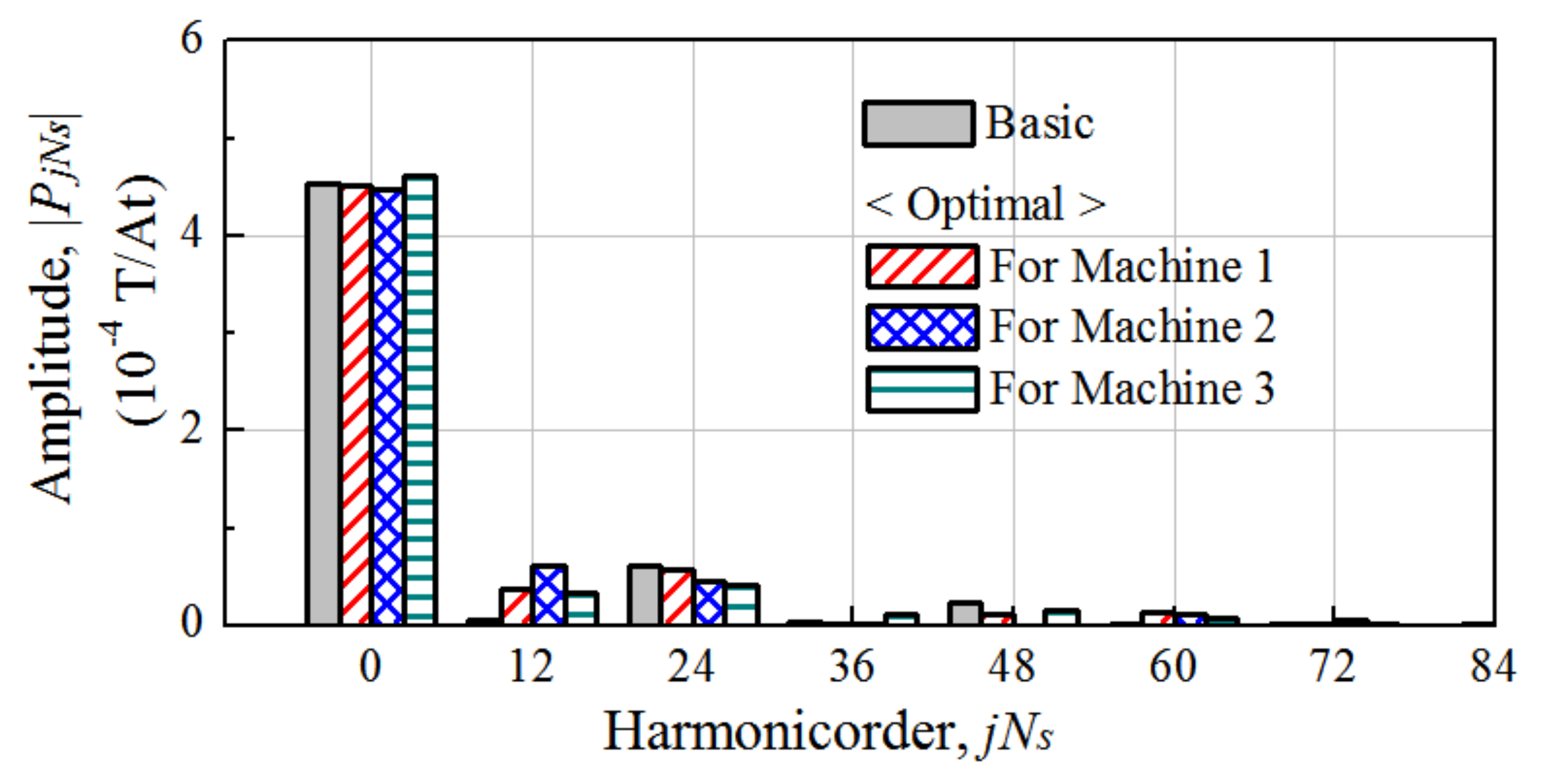
Table 1 shows the optimal results for the machines. Figure 5 compares the radial flux density distributions by the armature windings for the machines with the optimal FMP shapes. The results from the analytical method are in good agreement with the FEA results. By changing from a basic FMP shape to the optimal FMP shapes, the working harmonics in Machines 1, 2, and 3 were improved by 8.6%, 23.6%, and 22.1%, respectively. Figure 6 shows the harmonic components of the permeance distributions for the optimal FMP shapes. Figure 7 compares the components of the working harmonics for Machines 1, 2, and 3. The variations of the design variables changed not only the permeance harmonics but also the winding MMF harmonics as a result of the slot open, as expressed in (3)–(5). Hence, based on (11), (13), and (15), the optimal FMP shapes for Machines 1, 2, and 3 were obtained by considering the harmonic characteristics of the winding MMF and permeance that varied by the design variables.

3.2. Back EMF and Torque Characteristics

Table 2 shows the 2D FEA results for the back electro-motive force (EMF) and the output torque. For a fair comparison, the structure of the rotor was employed identically. The rotating speed of the rotor was 500 rpm and the rated phase current was 10 A. Compared with the basic FMP shape, in which the FMPs are equally spaced, the back EMF and the output torque in Machines 1, 2, and 3 with the optimal FMP shapes were improved by 8.4%, 23.2%, and 22.1%, respectively. For the air-gap flux density harmonic corresponding to the number of stator pole-pairs, the winding factors for Machines 1, 2, and 3 were 0.5, 0.866, and 0.933, respectively [17]. Hence, it can be noted that the winding configuration for Machine 3 had an advantage over the others in terms of the back EMF and torque. In all machines, the increase ratios of the performances had the same trend as the increased ratios of the working harmonics.

4. Experiment and Conclusions

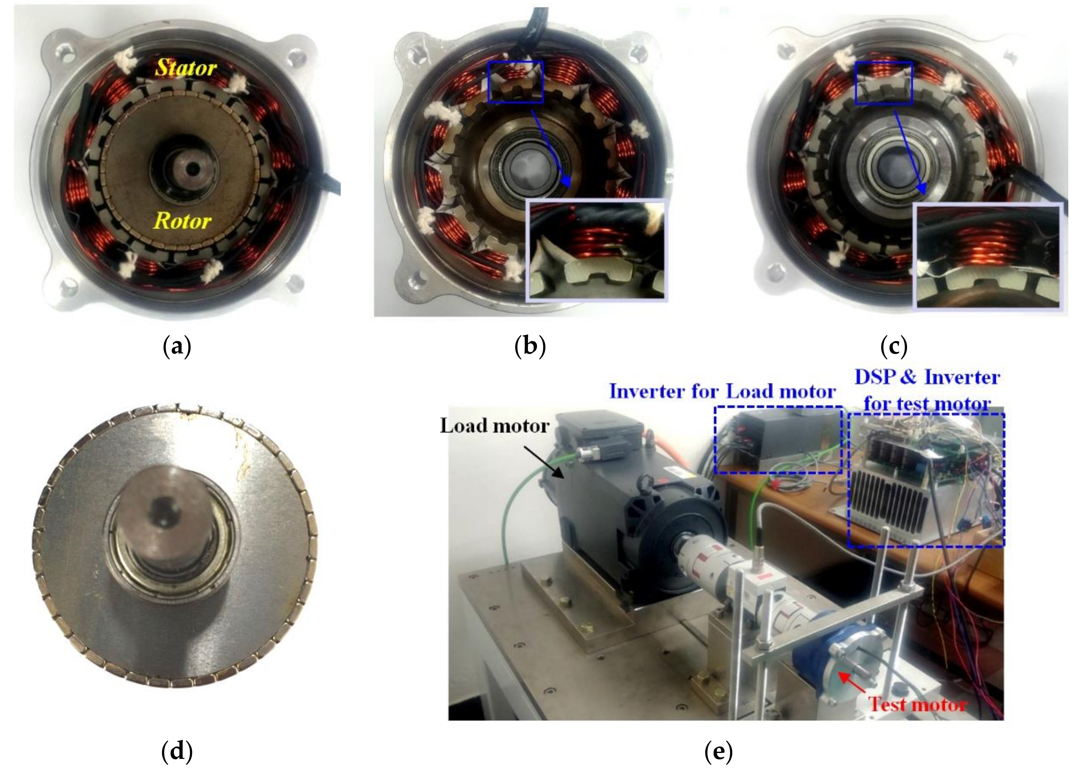
Figure 8 shows the prototypes for Machine 3 with the basic and optimal FMP shapes. The experimental results for the back EMF are illustrated in Figure 9. It can be noted that the measured fundamental components were about 10% lower than the FEA results, which was mainly because of the effect of lamination, the end effects, and a manufacturing error. However, the back EMF for the optimal FMP shape increased by 24.6% compared to that for the basic FMP shape, as shown in Figure 9b. Figure 10 shows the experiment results for the output torque according to the input current when the rotor rotated at 1500 rpm. The differences between the FEA and experimental results for the output torque were about 19% for the basic model and 17% for the optimal model due to the losses of the motor, such as the mechanical and electromagnetic losses. In the test, the input current included the loss components, thus the ratio of the average torque to the input current was lower than the FEA results. Although the input current increased in the experiment, two prototypes were tested in the same conditions and had distinct differences in the torque performance. Namely, by designing the FMP shape with consideration to the harmonics characteristics of the winding MMF and permeance, the output torque of the SPMVM was increased by 24.2%. Moreover, it was found that the increase ratio of the average torque was similar to that of the back EMF from the experimental results.
This paper proposed the design method of the SPMVM with consideration to the winding MMF harmonics. The goal was to determine the geometric shape of the FMPs by adjusting the harmonics of the permeance according to the harmonic characteristics of the winding MMF. To do so, based on the Fourier analysis method, the analytical equation for the flux density distribution by the winding MMF in the air-gap was derived. Consequently, the amplitude of the working harmonic was formulated into an analytical equation that consisted of the design variables for the FMP shape. Consequently, the proposed method could optimally design the FMP shape based on the mathematical analysis for the effects of the variations of the winding configuration and the FMP shape on the working harmonic. From the experiment, it was validated that the proposed method could improve the output power of the SPMVM.

Author Contributions

All authors contributed to this work. D.J. was the main author of this manuscript and contributed to the theoretical analysis, simulation, experiment, and manuscript preparation. J.C. provided technical guidance for research work and supervised the whole project.

Funding

This work is funded by Dong-A University Research Fund.

Conflicts of Interest

The authors declare no conflict of interest.

References

  1. Zhao, F.; Kim, M.; Kwon, B.; Baek, J. A small axial-flux vernier machine with ring-type magnets for the auto-focusing lens drive system. IEEE Trans. Magn. 2016, 52, 1–4. [Google Scholar] [CrossRef]
  2. Xu, L.; Liu, G.; Zhao, W.; Yang, X.; Cheng, R. Hybrid stator design of fault-tolerant permanent-magnet vernier machines for direct-drive applications. IEEE Trans. Ind. Electron. 2017, 64, 179–190. [Google Scholar] [CrossRef]
  3. Liu, Y.; Ho, S.L.; Fu, W.N.; Zhang, X. Design optimization of a novel doubly fed dual-rotor flux-modulated machine for hybrid electric vehicles. IEEE Trans. Magn. 2015, 51, 1–4. [Google Scholar]
  4. Liu, G.; Yang, J.; Zhao, W.; Ji, J.; Chen, Q.; Gong, W. Design and analysis of a new fault-tolerant permanent-magnet vernier machine for electric vehicles. IEEE Trans. Magn. 2012, 48, 4176–4179. [Google Scholar] [CrossRef]
  5. Jia, S.; Qu, R.; Li, D.; Li, J. A high torque density vernier PM machines for hybrid electric vehicle applications. In Proceedings of the 2016 IEEE Vehicle Power and Propulsion Conference (VPPC), Hangzhou, China, 17–20 October 2016. [Google Scholar]
  6. B. Design of a Direct Drive Permanent Magnet Vernier Generator for a Wind Turbine System. In Proceedings of the IEEE Energy Conversion Congress and Exposition (ECCE), Portland, OR, USA, 23–27 September 2018; pp. 4275–4282.
  7. Li, X.; Chau, K.T.; Cheng, M. Analysis, design and experimental verification of a field-modulated permanent-magnet machine for direct-drive wind turbines. IET Electr. Power Appl. 2015, 9, 150–159. [Google Scholar] [CrossRef]
  8. Gao, Y.; Qu, R.; Li, D.; Li, J.; Zhou, G. Design of a dual-stator LTS vernier machine for direct-drive wind power generation. IEEE Trans. Appl. Supercond. 2016, 26, 1–5. [Google Scholar] [CrossRef]
  9. Wn, F.; El-Refaie, A.M. Permanent magnet vernier machine: A review. IET Electr. Power Appl. 2019, 13, 127–137. [Google Scholar]
  10. Niu, S.; Ho, S.L.; Fu, W.N.; Wang, L.L. Quantitative comparison of novel vernier permanent magnet machines. IEEE Trans. Magn. 2010, 46, 2032–2035. [Google Scholar] [CrossRef]
  11. Toba, A.; Lipo, T.A. Generic torque-maximizing design methodology of surface permanent-magnet vernier machine. IEEE Trans. Ind. Appl. 2000, 36, 1539–1546. [Google Scholar]
  12. Vukoti´c, M.; Miljavec, D. Design of a permanent-magnet flux-modulated machine with a high torque density and high power factor. IET Electr. Power Appl. 2016, 10, 36–44. [Google Scholar] [CrossRef]
  13. Kim, B.; Lipo, T.A. Operation and design principles of a PM vernier motor. IEEE Trans. Ind. Appl. 2014, 50, 3656–3663. [Google Scholar] [CrossRef]
  14. Jang, D.; Chang, J. Influences of winding MMF harmonics on torque characteristics in surface-mounted permanent magnet vernier machines. Energies 2017, 10, 580. [Google Scholar] [CrossRef]
  15. Clayton, A.E. A mathematical development of the theory of the magnetomotive force of windings. J. Inst. Electr. Eng. 1923, 61, 749–787. [Google Scholar] [CrossRef]
  16. Zhu, Z.Q.; Howe, D. Instantaneous magnetic field distribution in brushless permanent magnet dc motors, Part III. Effect of stator slotting. IEEE Trans. Magn. 1933, 29, 143–151. [Google Scholar] [CrossRef]
  17. Ishak, D.; Zhu, Z.Q.; Howe, D. Comparison of PM brushless motors, having either all teeth or alternate teeth wound. IEEE Trans. Energy Convers. 2006, 21, 95–103. [Google Scholar] [CrossRef]
Figure 1. Structures of the surface-mounted permanent magnet vernier machines (SPMVM) and magnetic-flux line produced by the windings. (a) Machine 1; (b) Machine 2; (c) Machine 3.
Energies 12 00897 g001
Figure 2. Winding magneto-motive force (MMF) distributions. (a) Machine 1; (b) Machine 2; (c) Machine 3; (d) comparison of spectra.
Energies 12 00897 g002
Figure 3. Air-gap permeance because of the flux modulation poles (FMPs). (a) Design variables for the FMPs; (b) distribution of the air-gap permeance.
Energies 12 00897 g003
Figure 4. Local minimum values of permeance. (a) Pθ1 according to θ1 (b) Pso according to θso.
Energies 12 00897 g004
Figure 5. Radial flux density in Machines 1, 2, and 3 with the optimal FMP shapes. (a) Machine 1; (b) Machine 2; (c) Machine 3.
Energies 12 00897 g005
Figure 6. Harmonic components of the air-gap permeance for the optimal FMP shapes.
Energies 12 00897 g006
Figure 7. Components of the working harmonics in Machines 1, 2, and 3 according to the FMP shape.
Energies 12 00897 g007
Figure 8. Prototypes for Machine 3. (a) Structure of the stator and rotor; (b) the stator with basic FMP shape; (c) the stator with optimal FMP shape; (d) the rotor; (e) experimental setup.
Energies 12 00897 g008
Figure 9. Experimental results for the back EMF. (a) Waveforms; (b) harmonics.
Energies 12 00897 g009
Figure 10. Experimental results for the output torque. (a) Measured results; (b) average torque along with the current.
Energies 12 00897 g010
Table 1. Optimization results for Machines 1, 2, and 3.
MachineFMP ShapeDesign Variables [degree]Working Harmonic [mT]
θ1θ2θsoAnalyticalFEA
1Basic7.57.57.510.3110.33
Optimal10.6475.3611.2711.22
2Basic7.57.57.514.4514.38
Optimal12.387.053.5217.9617.77
3Basic7.57.57.515.4715.26
Optimal8.828.59418.9518.62
Table 2. 2D finite element analysis (FEA) results for the back electro-motive force (EMF) and output torque for Machines 1, 2, and 3.
MachineFMP ShapeFundamental of Back-EMF [VLL]Average Torque [Nm]Torque Ripple [%]
1Basic4.4 (100%)1.03 (100%)7.5
Optimal4.77 (108.4%)1.12 (108.4%)4.2
2Basic5.62 (100%)1.32 (100%)3.7
Optimal6.93 (123.2%)1.62 (123.2%)3.8
3Basic5.71 (100%)1.34 (100%)1.9
Optimal6.97 (122.1%)1.63 (122.1%)1.4