Optimization of the Electrolyte Parameters and Components in Zinc Particle Fuel Cells
by
 , ,
, ,
Thangavel Sangeetha
1,2,† ,
,
Po-Tuan Chen
3,†,
Wu-Fu Cheng
4,
Wei-Mon Yan
1,2,* and
K. David Huang
4,* 1
Department of Energy and Refrigerating Air-Conditioning Engineering, National Taipei University of Technology, Taipei 10608, Taiwan
2
Research Center of Energy Conservation for New Generation of Residential, Commercial, and Industrial Sectors, National Taipei University of Technology, Taipei 10608, Taiwan
3
Center for Condensed Matter Sciences, National Taiwan University, Taipei 10617, Taiwan
4
Department of Vehicle Engineering, National Taipei University of Technology, Taipei 10608, Taiwan
*
Authors to whom correspondence should be addressed.
†
These authors contributed equally to this work (TS and PTC).
Energies 2019, 12(6), 1090; https://doi.org/10.3390/en12061090
Submission received: 18 February 2019
/
Revised: 19 March 2019
/
Accepted: 19 March 2019
/
Published: 21 March 2019
Abstract
:Zinc (Zn)-air fuel cells (ZAFC) are a widely-acknowledged type of metal air fuel cells, but optimization of several operational parameters and components will facilitate enhanced power performance. This research study has been focused on the investigation of ZAFC Zn particle fuel with flowing potassium hydroxide (KOH) electrolyte. Parameters like optimum electrolyte concentration, temperature, and flow velocity were optimized. Moreover, ZAFC components like anode current collector and cathode conductor material were varied and the appropriate materials were designated. Power performance was analyzed in terms of open circuit voltage (OCV), power, and current density production and were used to justify the results of the study. The flow rate of the electrolyte was determined as 150 mL/min in the self-designed configuration. KOH electrolyte of 40 wt% concentration, at a temperature of 55 to 65 ℃, and with a flow velocity of 0.12 m/s was considered to be beneficial for the ZAFCs operated in this study. Nickel mesh with a surface area of 400 cm2 was chosen as anode current collector and copper plate was considered as cathode conductor material in the fuel cells designed and operated in this study. The power production of this study was better compared to some previously published works. Thus, effective enhancement and upgrading process of the ZAFCs will definitely provide great opportunities for their applications in the future.
1. Introduction
The demands for energy have triggered issues like the energy crisis, climate change, and environmental pollution. Fossil fuels are unreliable and unsustainable due to their depleting supplies and negative impacts on the environment [1]. So, in recent years, the development of renewable energy has propelled and accelerated the inevitable transition from fossil fuels to next-generation power sources. As a result, researchers are focusing on alternative, renewable, and carbon-neutral energy sources which are necessary for economic and environmental sustainability [2]. Among various renewable energy sources, fuel cells which are capable of converting chemical energy through electrochemical reaction of cathode and anode into electric energy are highly preferred. Among them, Zinc (Zn)-air fuel cells (ZAFCs) have various advantages such as (i) abundant availability of raw Zn in the earth; (ii) stable discharge performance; (iii) being environmentally friendly in nature; and (iv) effective utilization for energy storage purposes [3]. Mechanically rechargeable ZAFCSs are of two basic types: (1) reconstructable ZAFCs and (2) refuelable ZAFCs. In the reconstructable ones, the Zn plates are replaced and regenerated after the discharge process. In the refuelable type, aqueous flowing electrolytes are employed in the cells, which pass through a packed bed of Zn particles that corrode and are discharged by gravitational force [4]. There are research studies that have reported various mechanisms to improve ZAFC performance like employing electrolytes and optimizing their parameters and choosing the right components for the ZAFC like anode fuel type, current collectors, and conductor materials at the air cathode [5].
The electrolyte is mainly used for the purpose of charge transfer between the positive and negative electrodes inside a cell. Earlier ZAFCs used acidic electrolytes, but due to poor performance, alkaline aqueous electrolytes like potassium hydroxide (KOH) were adopted [6]. Mele et al [7] have employed a tapered-end flow ZAFC with flowing KOH electrolyte which is mechanically refuelable with Zn microspheres. They used this to estimate the effects of KOH aging on the Zn anode and observed improved performance and stability. The parameters of the KOH electrolyte, like concentration, temperature, and flow patterns, were optimized in a regenerative type ZAFC by Wang et al [8]. They reported that among all the cell components, flowing electrolytes played an inevitable role in controlling the Zn deposition and influencing its performance to a larger extent. This can also avoid issues like passivation formation, non-uniform Zn dissolution and deposition, and hydrogen evolution. The clogging problem of the unreacted Zn, solid products, and byproducts in the electrolyte will reduce the electrolyte ionic conductivity and increase the concentration polarization. While an alkaline electrolyte is pumped into the battery, the flow will wash away dissolved products and refresh the active surfaces [9]. Thus, optimization of the significant parameters of the flowing electrolyte was considered to be of utmost importance in the present study.
Anode fuel type is a vital component in a ZAFC and Zn particles can be used as a fuel supply in a flow mode instead of Zn plates. In recent decade, porous Zn plates have been commercially used as anodes for ZAFCs. The porous structure possesses a high ratio of active surface which enhances the collision with electrolyte molecules and increases the reaction rate [10]. Nevertheless, they have the following positive impacts: (i) Zn particles possess larger surface areas for reaction compared to Zn plate, which is advantageous, and (ii) particle anode with flowing electrolyte is highly advantageous as this may suppress hydrogen evolution reaction (HER) and thus improve cell performance and electricity production. The reaction of Zn particles will produce zincate ions (Zn(OH)42+), which can be dissolved in the electrolyte. Once the concentration of zincate in the electrolyte gets saturated, zinc oxide (ZnO) is formed. This product can be washed away by the flowing electrolyte to maintain reaction equilibrium. Zn particles possess a larger reaction area than Zn plate to enhance the reaction efficiency [11]. Fuel cells require a continuous supply of fuel to sustain the chemical reactions for unceasing electricity production. The adoption of a circulating flow type electrolyte system will result in the removal of spent Zn anodes, meanwhile, the Zn fuel can also be continually added to the reaction tank via the flowing electrolyte. Accordingly, the reactant elimination can still be re-supplied smoothly without mechanical exchange [12]. Thus, due to the above-mentioned advantages, the anode fuel type used in the present study was comprised of Zn particles and this study is focused on proposing a fuel cell system with flowing Zn particle fuel.
Current collectors are inevitable and very important components in a ZAFC, and they are made of various metals like nickel (Ni), stainless steel, iron, copper, silver (Ag), and gold (Au). They play a very vital role in the successful operation of the fuel cell. Zn and atmospheric air are the oxidant sources in a ZAFC. Zn undergoes oxidation and electrons are collected by the anode current collector and they get converted to cations (ZnO). During the conversion of Zn to ZnO, electrons are produced and transported to the anodic current collector and they cross the external load and return to the cathode current collector, where the reduction reactions result in the generation of hydroxyl ions [13]. Efficient surface area, porosity, and conductivity are significant characteristics for both anode and cathode current collectors as these properties will enhance the HER and the oxygen reduction reaction (ORR) and eventually the fuel cell performance. Pieces of Ni mesh with different surface areas were used as anode current collectors in the ZAFCs and their effects were determined in the present study. Air-cathodes in ZAFCs are usually made up of catalyst and diffusion layers and materials like polytetrafluoroethylene (PTFE) are used as hydrophobic binders in those layers. According to that the cathodes may have single or double layers of binders. Porosity, hydrophobicity, stability, better oxygen, and electron and proton conductivity are some characters of air-cathodes [3]. The air-cathodes used in the present study were made of carbon black, so a novel attempt of using a different metallic layer for better electron conductivity has been investigated. Their effects on the power performance of the ZAFCs was determined.
2. Methodology
2.1. Construction of Experimental System Platform
The experimental test platform for the ZAFC included the fuel cell body, electronic load, magnet mixer, electrolyte, silica gel heating film, temperature control measuring device, temperature sensor, peristaltic pump, and monitoring computer. Zn particles were employed as anode fuel and the flowing electrolyte was KOH solution. It was stirred with a magnetic stirrer to ensure uniform mixing and was heated through a series of heating film sheets. The temperature of the electrolyte was controlled by temperature controller and the flow was adjusted by peristaltic pump. The electronic loading device and AC impedance analyzer were connected to the cell. Finally, the cell was regulated by the computer-controlling electronic loading to discharging with constant current, while the computer recorded the performance data. The configuration planning of the overall experimental platform has been portrayed in Figure 1.
2.2. Construction of Zn-air Fuel Cells
Zn-air fuel cell utilizes O2 and Zn particles as cathode and anode respectively. The Zn particle fuel cell employed in this experiment is self-fabricated, as shown in Figure 2a. The actual photograph of the cell is shown in Figure 2b. The anode fuel consisted of Zn particles which were commercially purchased from First Chemical Co., Ltd, Taipei, Taiwan. The particles were of 0.5 mm radius with a surface area of 3.14 mm2. They were inserted into the anode chamber through an opening at the top of the frame.
Zn particles were soaked in KOH solution for 6 h before prior to usage as anode fuel in the ZAFC. The outer shell of the fuel cell was made of stainless steel as it was resistant to corrosion and also facilitated frequent disassembling. The cathode chamber primarily consisted of current collector and carbon black as air electrode set up. The external interface of the air electrode was made of hydrophobic and porous Teflon sheets. The thickness of the Teflon sheet, air electrode, and separator was 0.3 mm, and that of the anode chamber was 8 mm. Non-woven fabric material was chosen as the separator material. Besides, the Teflon could allow the external O2 to enter the active site of the catalyst and prevent the overflow of internal electrolyte. The air cathode also possessed a manganese-based catalyst (Evionyx-Taiwan Co., Ltd., Taiwan), with an active area of 3 × 16 cm2. Oxygen was flux-fed in a gas distribution plate and was reduced to hydroxyl ions, completing the discharging process. The carbon black was a porous material with embedded catalyst and it was capable of achieving uniform gas diffusion. The inner side of Zn anode electrode housed a separator to prevent the Zn anode from contacting with the cathode. The KOH electrolyte was circulated by a peristaltic pump.
2.3. Measurements and Analyses
ZAFC operation with an external load lead to various discharge modes such as constant current, constant voltage, and constant power. The volt method facilitated the occurrence of a specific chemical reaction mechanism by external voltage or current and the reactions varied with the applied voltage or current. The constant current method, also known as chronoelectric potential or current voltammetry, was investigated in this study. To further check the reactor performance, they were subjected to polarization and power density curve analysis by Electrochemical Impedance Spectroscopy (EIS). After 4 hours in the open circuit condition, the polarization curves were measured under the same open-circuit conditions at a scan rate of 0.5A/30s [6]. The discharge curves of the cell under various loads were observed. The influences of the concentration, temperature and flow velocity of KOH electrolyte were analyzed in this study along with the effects of different current collector surface areas and conductor materials for the air-cathode. The peristaltic pump was used to control the flow velocity of the electrolyte. The electrochemical characterization of polarization curves of the ZAFC was performed at room temperature with an increasing current of 1 A per minute, using a multifunctional DC electronic load (PLZ-4W-664WA 0-150V 132A 660W, Kikusui Electronics Corp., Japan).
3. Results and Discussion
An attempt has been made in this study to construct and operate ZAFCs with Zn particle as anode fuel and flowing KOH electrolyte. The effects of the electrolyte concentration, temperature, and flow velocities on the power performance of the ZAFC have been investigated. Moreover, the anode current collector surface area and cathode conductor material have been varied to determine their impacts on the fuel cell performance.
3.1. Effects of Flowing Electrolyte Parameters on ZAFC Power Performance
The operation of a fuel cell with a flowing electrolyte has many benefits such as: (i) a flowing electrolyte can exclude away discharge products in the fuel cells without affecting the electrochemical reactions, and (ii) it may also reduce the heat and wash away the gas bubbles generated by the reactions and will manage the battery thermal system [14]. Power performance of the ZAFCs with respect to all the above-mentioned parameters were significantly analyzed by the polarization curves. They are used to determine the operative conditions under load (external resistance). The polarization curves are usually used to identify four important losses: (i) fuel crossover losses due to the depletion of fuel passing through the electrolyte; (ii) activation losses due to slow reaction kinetics on the surface of the electrodes; (iii) ohmic losses due to the resistance present for the flow of electrons and ions through electrodes and electrolytes, respectively; and (iv) the concentration losses due to the changes in reactant concentrations on the electrode surfaces [15,16].
3.1.1. Concentration of Electrolyte
The dry separator layers were soaked in the KOH electrolyte prior to experiments for about 10 minutes in order to improve the ion transfer impedance. Discharge tests were carried out during the process, the cell voltage was monitored, and when a stable value of 1.29 V was obtained, the subsequent measurements were started. The concentration of KOH electrolyte was correlated with its electrical conductivity. Moreover, the OH− in the electrolyte was a reactant for the anode, but it was a product from the cathode, and therefore the Zn anode and air cathode have different demands for electrolyte OH−. Generally, higher concentrations of electrolyte resulted in enhanced performance, but over a critical concentration, the performance reduced. Therefore, different electrolyte concentrations were then investigated using constant current discharge. The variations of IV curve under low and high currents were measured. The concentration parameters were set from 20 wt%−60 wt% as the saturated concentration of KOH is 65 wt% for measurements. The open circuit voltage (OCV) increased with the increase of electrolyte concentration from 20 wt% (1.3 V) to 30 wt% (1.33 V) and 40 wt% (1.4 V), but further increase to 50 wt% (1.41 V) and 60 wt%(1.41 V) did not result in a significant increase in voltage output (Figure 3a).
Nevertheless, electrolyte concentration increase, resulted in an increase in current density production as well and the trend followed by the current density output was different to that of the voltage production (Figure 3b). A maximum cell voltage at 200 mA cm−2 was obtained at the KOH concentration of 40 wt%, but further increase in the electrolyte concentration reduced the cell voltage. The relationship between the electrolyte concentration and power output can be better explained by the Nernst equation which indicates the affiliation between the reversible potential (E0) of electrochemical reaction, temperature, derive current density and standard potentials [17,18]. The reversible potential increases with reactant amount, but decreases with product concentration. In the Equation (1), the anodic reaction of Zn is:
Zn is solid, so the anodic reaction potential of Zn can be expressed as follows:
Cathodic reaction mode:
The cathode reaction potential is
So according to Equation (2), the reasons for the power output changes with respect to KOH concentrations can be explained as follows: (1) Zn anode reactant is OH−, and the reaction potential increases with the increase of OH− concentration. (2) Equation (3) shows that the product of air cathode is OH−. The reaction potential decreases with the increase of the concentration of OH−, and increases with the increase of the oxygen concentration of the reactant. The anode and cathode required contrasting concentrations of OH− (3). In addition, if the concentration of KOH is low, the electrolyte possesses higher resistance which leads to serious anode polarization, and when the concentration is increased, the performance of the cathode will be reduced due to polarization caused by large current discharge. These facts have been validated by Wang et al [9], where they have explained that the flowing electrolyte concentration in a ZAFC plays a potential role in determining the ionic current output and conductivity. They also explained the Nernst equation and determined the association between OH−and the electrochemical reactions at the anode and cathode. The cell kinetics are largely dependent on the effect of OH− ions on zinc deposition in ZAFC, because the convection between zincate ions and OH− during zinc deposition plays a key mechanism.
The solubility and deposition of zincate ions depend on the saturation level of the electrolyte and thus governing the power performance of the fuel cell [19,20]. Zhang [21] have indicated that the solubility of Zn depended on KOH concentration. The electrode potential decreased with increasing electrolyte concentrations, but on the contrary, the current and conductivity increased. This occurred till a concentration of 30%, but then decreased with further increase in concentration. For effective ZAFC performance, the KOH concentrations should be of 20–40% as in this range the solubility is almost 1 mol/L. The effects of electrolyte concentrations on Zn deposit morphology in a ZAFC were investigated by Gavrilović-Wohlmuther et al. [22]. They used three types of KOH concentrations like 0.2, 0.5, and 1 M in a Zn plate anode ZAFC. The 0.5 M KOH concentration electrolyte was observed to have induced the ZAFC to produce 10 times higher current density values than the other two concentrations, thus enhancing the cell performance. Thus, in acceptance with the above mentioned justifications, 40% KOH concentration was found to be suitable for the ZAFC operated in the present study.
3.1.2. Flowing Electrolyte Temperature
The temperature of the KOH electrolyte would prominently affect the performance behavior of the ZAFC [23]. The fuel cells were operated under five different temperatures like room temperature (28 ℃), 35 ℃, 45 ℃, 55 ℃, and 65 ℃ and electrolyte solutions with concentrations of 20, 40, and 60% were subjected to these temperature variations. Experiment results revealed that the temperature of the electrolyte influenced the chemical reactions and increased the chemical activity (Figure 4a). The OCV increased in parallel with temperature and a maximum of 1.42 V was produced at 65 ℃. However, the electrolyte was observed to vaporize at temperatures higher than 65 ℃ thus further reducing the voltage production. In contrast, at low temperatures, the performance of the cell was lower and a minimum voltage of 1.32 V was produced at 28 ℃. Thus the figure shows that the maximum OCV were produced only at highest current density of 200 mA/m2. This may be due to the decreased ion transfer capacity of the electrolyte at low temperatures and drying out of the air-electrode at very high temperatures. According to Equation (4), water depletion in the electrolyte solution might lead to increased product concentration at the air electrode, and decreased concentration of reactants. This might have been the reason for the reduced cathode reaction and OCV. The significant results of the study have been substantiated by results from other researchers. At very high electrolyte temperatures, ZAFCs might absorb water from the atmosphere through the cathode leading to air electrode flooding, but at very low temperatures, they may release water vapor through the air cathode. This may result in further leakage and practical difficulties, thus finding out an optimum electrolyte operating temperature is much more than important in ZAFCs [24].
Figure 4b reveals the OCV production in ZAFC with respect to KOH electrolyte operated with three different concentrations (20, 40, and 60 wt%), at five different temperatures (28 ℃, 35 ℃, 45 ℃, 55 ℃, and 65 ℃) and only at the maximum current density of 200 mA/m2. The ZAFC operated with optimum electrolyte concentration of 40% chosen in this study has produced increased voltage at a higher electrolyte temperature of 65 ℃ (1.42 V). The results thus ascertained that the fuel cell operated with the optimized electrolyte concentration (60 wt%) and temperature (65 ℃) produced the maximum OCV (1.42 V) at the highest current density (200 mA/m2). Thus proving the fact that better performance of the fuel cell was obviously dependent on electrolyte parameters and also that each parameter was inter connected with one another. Gavrilović-Wohlmuther et al. [22] designed and operated ZAFCs at three different electrolyte temperatures (25 ℃, 50 ℃, and 70 ℃). They investigated the effect of electrolyte temperature on Zn plating, Zn crystals formation and dissolution They reported that higher electrolyte operating temperatures in ZAFCs were more beneficial as this resulted in increased electrolyte conductivity, salt solubility, and air electrode kinetics. The electrolyte viscosity was also reduced with increasing temperatures. Thus, the ionic mobility of the zincate ions was increased and this eventually led to high limiting current density production and thus, almost 10 times higher current density values than that of low temperatures (10 mA/cm2) were produced at higher temperatures (100 mA/cm2). The zincate ion formation and deposition on the ZAFC electrodes were observed to be different when the temperature was varied. Lower temperatures resulted in mossy type of formations but higher and very high temperatures lead zincate ions to get deposited as spongy dendrites which had poorer attachment on the electrodes, low solubility and were easy to be washed away after the discharge processes [25]. Thus considering the above mentioned results and significant substantiations, KOH electrolyte with a temperature of 55 to 65 ℃ was considered to be beneficial for the ZAFCs operated in this study.
3.1.3. Influence of Electrolyte Flow Velocity
The velocity of the flowing electrolyte can have numerous influences on the ZAFC components and behavior. A right flow velocity can have positive impacts in ZAFC and will evidently enhance the power performance, durability and stability [12]. Therefore, the effects of different electrolyte flow velocities on the ZAFC were controlled by a peristaltic pump and investigated in this study such as 0 m/s, 0.06 m/s, 0.12 m/s, and 0.18 m/s with a KOH concentration of 40wt %. The results are depicted in Figure 5a,b, When the electrolyte had no flow, the concentration of products increased continuously. OCV output increased from no flow conditions (1.35 V) to 0.06 m/s (1.38 V), till 0.12 m/s (1.45 V). But further rise in velocity to 0.18m/s resulted in a sudden fall of OCV to 1.36 V.
Another reason may be that the high flow velocity might have caused a high pressure inside the cell thus leading to air cathode flooding. When the flow velocity of the KOH electrolyte was 0.06–0.12 m/s, the voltage was higher, but when the flow velocity was further accelerated to 0.18 m/s, the flow regime of the electrolyte inside the fuel cell was too fast, which might have resulted in incomplete chemical reaction and irregular voltage production and downfall. Zincate ions will get dissolved in electrolyte and will be brought by circulating flow to electrolysis tank. Zn fuel can also be continually added to the reaction tank through the flowing electrolyte. The reactant supplement can be effectively performed, instead of mechanically exchanging Zn plates. However, zincate ions may get precipitated as solid ZnO if the solution is oversaturated with zincate ions. The reaction has been represented below.
Zn(OH)42− → ZnO + 2(OH)− + H2O
Solid ZnO are electrical insulators and possess higher molar volumes than metallic Zn; consequently. Their precipitation in a ZAFC will lead to pore blockage gradually decreasing the specific capacity of the cell. The relevant precipitation rates depended on alkali concentration, initial electrode porosity, and applied current density. Therefore, the electrolyte flow velocity has been considered crucial in terms of adjusting the effect of ZnO exclusion. It has been vindicated with the help of forthcoming research works. Very high flow rates of the electrolyte may lead to non-uniform current density distribution and concentration gradients which may result in uneven redistribution of zinc active materials on the electrode surfaces. Other impacts are decrease of porosity, passivation and active surface areas of the electrode, and thereby reduction of electrode kinetics [26]. Pei et al. [27] operated ZAFCs and reported that very less electrolyte flow rates may lead to insufficient KOH and oxygen delivery and too high flow rates may alter the renewal rate of electrolyte OH− concentration and dissolution of the zincate ions in the electrolyte. Thus, flow rates should be able to provide OH− according to reaction stoichiometry and remove the reaction product, or else ZnO formation can cause concentration polarization and reduced performance. The fundamental reasons for the performance of ZAFC with respect to flow may be due to mass transfer differences and crossover effects of zincate ions due to flow [27]. When the concentration of zincate ions approached saturation, the surface of Zn anode would react directly to ZnO, thus reducing the area for anode reaction and decreasing the fuel cell performance. ZAFCs were operated under three electrolyte flow velocities of 0.5, 4, and 15 cm/s by [10]. They observed that as flow velocity increased, the cell potentials also increased from 0.5 V to 2.8 V. They concluded that under linear velocities, the electrolyte inside the fuel cell can be continuously renewed, thus enhancing the long term performance. Gavrilović-Wohlmuther et al. [22] designed and operated ZAFCs at three different electrolyte flow velocities like 3, 6, and 16 cm/s. In the ZAFCs with linear velocity of 6 cm/s produced almost 5 times higher current density than the other velocity values. The surface analysis of the ZAFC anode revealed that medium velocities lead to spongy dendrites with poor attachment, low solubility and easy exclusion by the electrolyte. Thus considering the above mentioned results and significant substantiations, KOH electrolyte with a flow velocity of 0.12 m/s was considered to be beneficial for the ZAFCs operated in the present study.
3.2. Effect of Current Collector Surface area
Anode current collectors will facilitate the collection of electrons produced from oxidation of Zn anode fuel. As the Zn particles might possess unsteady and irregular contact surface, they may be inefficient in transporting electrons efficiently to the external circuit [28]. Thus the electron collection should be commenced by metal current collectors as they may have better surface area, conductivity, and steady and regular contact surface and porosity. The larger the contact area between the current collector and the Zn particles, the more effective the electron transportation will be. Thus, Ni meshes with different grid shapes and surface area values like 100 cm2, 300 cm2, and 400 cm2 were employed as anode current collectors and the effects were investigated on the ZAFCs performance in this study. Figure 6a shows the representation of the current collectors and their respective surface areas.
Figure 6b illustrates that increasing the collector area can improve the efficiency of electron collection and improve the power performance of the fuel cell. Maximum OCV of 1.4 V was produced by the ZAFC with an anode current collector of 400 cm2 surface area, whereas the others (100 cm2 and 300 cm2 produced 1.33 V and 1.35 V respectively). The reason might be that high surface area materials are capable of collecting more electrons compared to the lower surface area ones, thus accelerating the reaction kinetic rate. The shape of the grid may effectively resolve the efficiency and improve the contact area between the Zn particles and the current collector. The optimal grid shape was observed to increase the contact area by 30%. These results have been corroborated by some previously published studies as follows. Au and Ni mesh were employed as anode current collectors in the fuel cells operated by Asghar et al. [29]. Voltage, power, and current density values of 0.7 V, 1 A/cm2, and 357 mW/m2, respectively, were produced by the fuel cell with Au current collector, but when it was replaced by Ni mesh the values increased almost 2 fold to 1.1 V, 2.5 A/cm2, and 801 mW/m2. They stated that the better performance of Ni mesh might be due to its better catalytic properties. The high surface area and material densification in Ni mesh were crucial for efficient ionic transport and reaction kinetics. High surface area facilitated more ORR and HER reaction sites and this might have enabled high power performance of the fuel cell. Zhu et al. [5] operated fuel cells with Ni as anode current collector with an initial surface area of 0.3 cm2. Ni foam was used on the current collectors for active area enhancement and the surface area increased to 0.64 cm2. The microstructure characteristics of the material like the active surface area, porosity played an important role in ionic conduction and electrochemical kinetics thereby resulting in a heightened fuel cell performance.
3.3. Conductor Material at an Air Electrode
Cathodes are important elements in ZAFCs, and upgrading their structure will improve the conductivity, catalyst dispersibility, structure, porosity, hydrophobicity, and thereby the ORR, thus enhancing them. The cathode electrode of the ZAFC was made of Teflon, catalyst and carbon black, and electrons were transported through carbon black and catalyst. However, the conductivity of carbon black might be lesser than that of metals, so replacing that layer with a conductive metal layer was necessary. Therefore, the air cathode should be covered with a metal sheet to facilitate better electron conduction. Copper and stainless steel sheets were used as conductive materials and the air-cathode electrodes of the fuel cells were fabricated. As shown in Figure 7, the power performance of the fuel cells varied relatively with the metal used as conductive material. Copper (1.4 V) was observed to be much better than stainless steel (1.35 V) in voltage production. Replacing the material of the cathode conductive sheet with metal had a significant influence on the performance of the fuel cells. The metal might have reduced the ohmic overvoltage during discharge and increased the electron conduction efficiency of cathode electrode, thus enhancing the voltage and current density production. Fan and Su [30] designed and operated fuel cells with air cathodes that possessed triple conducting (oxygen, proton, and electron) capabilities. They were composed of lithium, nickel, and cobalt and their performance was compared with that of non-metal carbon electrodes fuel cells. The carbon electrode fuel cell produced voltage and current density of 0.5 V and 0.7 A/m2 respectively, whereas the triple metal electrode fuel cell was much superior in power production with a voltage of 1.0 V and current density of 1.5 A/m2. They reported that the significant reason behind this was the excellent and extrinsic conductivity properties and outstanding ORR activity displayed by the metal electrodes. Innovative stretchable copper conductor air cathodes were designed in ZAFC and a performance comparison with carbon cloth cathode ZAFC was done by Qu et al [31]. The metal electrodes were binder free and cost effective compared to carbon electrodes and the fuel cells produced much more energy density of 1084 Wh/Kg which was almost 2 fold higher than the values previously reported (573 Wh/Kg). Thus the above mentioned results made it evident that scaling up of ZAFC air-cathodes with metallic conductors is very crucial.
3.4. Power Density Curves
The fuel cell system was tested to discharge at constant power 3 W and the termination voltage was set at 0.8 V. The discharge was measured at constant power using 25 g of Zn powder. As illustrated in Figure 8a, the voltage of the cell exceeded 0.8 V at a time of about 230 minutes. The peak power density was 456 Wh/kg. The voltage drop attributed to the dissolution of Zn particles after reaction. The reaction surface between the Zn particles and the collector grid decreased, which made the cell unsustainable for voltage maintenance. A follow-up Zn particle-feeding design continuously supplied Zn particles to the fuel cell for further reactions. Maintaining the contact area between Zn particles and current collector enabled the cell to operate continuously with improved performance. The maximum power of the fuel cell is illustrated in Figure 8b, and the peak power was about 12 W. The peak current density was 300 mA/cm2 and the highest power corresponded to the voltage of 0.8 V. The power started decreasing when the voltage was lower than 0.8 V. Therefore, the operating voltage should be maintained at 0.8 V or higher for enhanced performance.
4. Conclusions
The investigation of the flow electrolyte parameters and their optimization in ZAFCs has been undertaken in this present study. The products of Zn(OH)42− can be dissolved in electrolyte and carried away by flow. The Zn anode can be maintained in the best reaction state. By controlling parameters of electrolyte flow, the active polarization, ohmic polarization, and concentration polarization of the cell reaction were reported to be reduced. The following are the findings and conclusions of the study
- A maximum cell voltage at 200 mA cm−2 was obtained at the KOH concentration of 40 wt%, but a further increase in the electrolyte concentration to 50 wt% and 60 wt% reduced the cell voltage. However, higher voltages can be maintained while discharging at high current densities.
- Furthermore, the increase of electrolyte temperature, resulted in an increase in the ionic conductivity. The temperature of the electrolyte increased from room temperature to 65 ℃, and the cell voltage increased obviously. The loss of H2O in electrolyte at higher temperature, aggravated the polarization concentration of the fuel cell, leading to a slow rise in voltage.
- The electrolyte flow velocity should be maintained at 0.12 m/s for an enhanced performance. The experimental results display that as the surface area and grid shape of the anode current conductor (Ni mesh) increased, more electrons were conducted and the fuel cell power production was increased. The shape and area of the collector grid should be designed to facilitate the addition of Zn particles and increase the area in a limited space.
- The air-cathode conductor material should be made of copper metal rather than carbon black, which can increase the ionic conductivity and facilitate heightened power performance of the ZAFC.
Author Contributions
Conceptualization, P.-T.C. and K.D.H.; Methodology, W.-F.C. and K.D.H.; Validation, W.-F.C.; Data Curation, W.-F.C.; Formal analysis, P.-T.C. and T.S.; Writing—Review and Editing, P.-T.C. and T.S.; Supervision, W.-M.Y. and K.D.H.
Funding
The authors appreciate the financial support from Ministry of Science and Technology, Taiwan, under grant number MOST 106-2218-E-027-014-MY2. The authors also acknowledge the financial support by the “Research Center of Energy Conservation for New Generation of Residential, Commercial, and Industrial Sectors” from The Featured Areas Research Center Program within the framework of the Higher Education Sprout Project by the Ministry of Education (MOE) in Taiwan. P.T.C. is thankful for the financial support from the Center of Atomic Initiative for New Materials, National Taiwan University, from the Featured Areas Research Center Program within the framework of the Higher Education Sprout Project by the Ministry of Education in Taiwan (108L9008).
Acknowledgments
We thank the graduate students in VULCES for their great efforts on the experiments.
Conflicts of Interest
The authors declare no conflict of interest.
References
- Wang, C.T.; Sangeetha, T.; Yan, W.M.; Chong, W.T.; Saw, L.H.; Zhao, F.; Chang, C.T.; Wang, C.H. Application of interface material and effects of oxygen gradient on the performance of single-chamber sediment microbial fuel cells (SSMFCs). J. Environ. Sci. 2019, 75, 163–168. [Google Scholar] [CrossRef] [PubMed]
- Wang, C.T.; Sangeetha, T.; Zhao, F.; Garg, A.; Chang, C.T.; Wang, C.H. Sludge selection on the performance of sediment microbial fuel cells. Int. J. Energy Res. 2018, 42, 4250–4255. [Google Scholar] [CrossRef]
- Oh, S.J.; Min, Y.J.; Lee, M.H.; Choi, J.H.; Kim, M.S.; Jo, N.J.; Eom, S. Design and electrochemical characteristics of single-layer cathode for flexible tubular type zinc-air fuel cells. J. Alloys Compd. 2018, 740, 895–900. [Google Scholar] [CrossRef]
- Xu, M.; Ivey, D.G.; Xie, Z.; Qu, W. Rechargeable Zn-air batteries: Progress in electrolyte development and cell configuration advancement. J. Power Sources 2015, 283, 358–371. [Google Scholar] [CrossRef]
- Zhu, B.; Huang, Y.; Fan, L.; Ma, Y.; Wang, B.; Xia, C.; Afzal, M.; Zhang, B.; Dong, W.; Wang, H.; et al. Novel fuel cell with nanocomposite functional layer designed by perovskite solar cell principle. Nano Energy 2016, 19, 156–164. [Google Scholar] [CrossRef]
- Huang, K.D.; Sangeetha, T.; Cheng, W.F.; Lin, C.; Chen, P.T. Computational fluid dynamics approach for performance prediction in a Zinc–air fuel cell. Energies 2018, 11, 2185. [Google Scholar] [CrossRef]
- Mele, C.; Bilotta, A.; Bocchetta, P.; Bozzini, B. Characterization of the particulate anode of a laboratory flow Zn–air fuel cell. J. Appl. Electrochem. 2017, 47, 877–888. [Google Scholar] [CrossRef]
- Wang, K.; Pei, P.; Wang, Y.; Liao, C.; Wang, W.; Huang, S. Advanced rechargeable zinc-air battery with parameter optimization. Appl. Energy 2018, 225, 848–856. [Google Scholar] [CrossRef]
- Wang, K.; Pei, P.; Ma, Z.; Xu, H.; Li, P.; Wang, X. Morphology control of zinc regeneration for zinc–air fuel cell and battery. J. Power Sources 2014, 271, 65–75. [Google Scholar] [CrossRef]
- Arenas, L.F.; Loh, A.; Trudgeon, D.P.; Li, X.; de León, C.P.; Walsh, F.C. The characteristics and performance of hybrid redox flow batteries with zinc negative electrodes for energy storage. Renew. Sustain. Energy Rev. 2018, 90, 992–1016. [Google Scholar] [CrossRef]
- Fu, J.; Cano, Z.P.; Park, M.G.; Yu, A.; Fowler, M.; Chen, Z. Electrically rechargeable zinc-air batteries: Progress, challenges, and perspectives. Adv. Mater. 2017, 29, 1604685. [Google Scholar] [CrossRef] [PubMed]
- Park, J.E.; Lim, M.S.; Kim, J.K.; Choi, H.J.; Sung, Y.E.; Cho, Y.H. Optimization of cell components and operating conditions in primary and rechargeable zinc–air battery. J. Ind. Eng. Chem. 2019, 69, 161–170. [Google Scholar] [CrossRef]
- Cai, X.; Lai, L.; Lin, J.; Shen, Z. Correction: Recent advances in air electrodes for Zn–air batteries: Electrocatalysis and structural design. Mater. Horiz. 2017, 4, 945–976. [Google Scholar] [CrossRef]
- An, K.; Zheng, Y.; Xu, X.; Wang, Y. Filter paper derived three-dimensional mesoporous carbon with Co3O4 loaded on surface: An excellent binder-free air-cathode for rechargeable Zinc-air battery. J. Solid State Chem. 2019, 270, 539–546. [Google Scholar] [CrossRef]
- Chen, Y.M.; Wang, C.T.; Yang, Y.C. Effect of wall boundary layer thickness on power performance of a recirculation microbial fuel cell. Energies 2018, 11, 1003. [Google Scholar] [CrossRef]
- Wang, C.T.; Huang, Y.S.; Sangeetha, T.; Yan, W.M. Assessment of recirculation batch mode operation in bufferless bio-cathode microbial fuel cells (MFCs). Appl. Energy 2018, 209, 120–126. [Google Scholar] [CrossRef]
- Lan, T.H.; Yan, W.M.; Sangeetha, T.; Ou, Y.T.; Wang, C.T.; Yang, Y.C. 2D Numerical physical model settings for three electron transfer pathways in microbial fuel cells. Sens. Mater. 2017, 29, 1055–1060. [Google Scholar] [CrossRef]
- Lan, T.H.; Wang, C.T.; Sangeetha, T.; Yang, Y.C.; Garg, A. Constructed mathematical model for nanowire electron transfer in microbial fuel cells. J. Power Sources 2018, 402, 483–488. [Google Scholar] [CrossRef]
- Zhu, A.L.; Wilkinson, D.P.; Zhang, X.; Xing, Y.; Rozhin, A.G.; Kulinich, S.A. Zinc regeneration in rechargeable zinc-air fuel cells—A review. J. Energy Storage 2016, 8, 35–50. [Google Scholar] [CrossRef]
- Mainar, A.R.; Iruin, E.; Colmenares, L.C.; Kvasha, A.; de Meatza, I.; Bengoechea, M.; Leonet, O.; Boyano, I.; Zhang, Z.; Blazquez, J.A. An overview of progress in electrolytes for secondary zinc-air batteries and other storage systems based on zinc. J. Energy Storage 2018, 15, 304–328. [Google Scholar] [CrossRef]
- Zhang, X.G. Secondary batteries–zinc systems| zinc electrodes: Overview. Encycl. Electrochem. Power Source 2009, 454–468. [Google Scholar] [CrossRef]
- Gavrilović-Wohlmuther, A.; Laskos, A.; Zelger, C.; Gollas, B.; Whitehead, A.H. Effects of electrolyte concentration, temperature, flow velocity and current density on Zn deposit morphology. J. Energy Power Eng. 2015, 9, 1019–1028. [Google Scholar] [CrossRef]
- Sapkota, P.; Kim, H. An experimental study on the performance of a zinc air fuel cell with inexpensive metal oxide catalysts and porous organic polymer separators. J. Ind. Eng. Chem. 2010, 16, 39–44. [Google Scholar] [CrossRef]
- Stamm, J.; Varzi, A.; Latz, A.; Horstmann, B. Modeling nucleation and growth of zinc oxide during discharge of primary zinc-air batteries. J. Power Sources 2017, 360, 136–149. [Google Scholar] [CrossRef] [Green Version]
- Pichler, B.; Weinberger, S.; Reščec, L.; Grimmer, I.; Gebetsroither, F.; Bitschnau, B.; Hacker, V. Bifunctional electrode performance for zinc-air flow cells with pulse charging. Electrochim. Acta 2017, 251, 488–497. [Google Scholar] [CrossRef]
- Pei, P.; Wang, K.; Ma, Z. Technologies for extending zinc–air battery’s cyclelife: A review. Appl. Energy 2014, 128, 315–324. [Google Scholar] [CrossRef]
- Pei, P.; Ma, Z.; Wang, K.; Wang, X.; Song, M.; Xu, H. High performance zinc air fuel cell stack. J. Power Sources 2014, 249, 13–20. [Google Scholar] [CrossRef]
- Xia, Y.; Liu, X.; Bai, Y.; Li, H.; Deng, X.; Niu, X.; Wu, X.; Zhou, D.; Lv, M.; Wang, Z.; et al. Electrical conductivity optimization in electrolyte-free fuel cells by single-component Ce0.8Sm0.2O2-δ–Li0.15Ni0.45Zn0.4 layer. RSC Adv. 2012, 2, 3828–3834. [Google Scholar] [CrossRef]
- Asghar, M.I.; Jouttijärvi, S.; Jokiranta, R.; Valtavirta, A.M.; Lund, P.D. Wide bandgap oxides for low-temperature single-layered nanocomposite fuel cell. Nano Energy 2018, 53, 391–397. [Google Scholar] [CrossRef]
- Fan, L.; Su, P.C. Layer-structured LiNi0. 8Co0. 2O2: A new triple (H+/O2−/e−) conducting cathode for low temperature proton conducting solid oxide fuel cells. J. Power Sources 2016, 306, 369–377. [Google Scholar] [CrossRef]
- Qu, S.; Song, Z.; Liu, J.; Li, Y.; Kou, Y.; Ma, C.; Han, X.; Deng, Y.; Zhao, N.; Hu, W.; et al. Electrochemical approach to prepare integrated air electrodes for highly stretchable zinc-air battery array with tunable output voltage and current for wearable electronics. Nano Energy 2017, 39, 101–110. [Google Scholar] [CrossRef]
Figure 1.
Structure of the experiment platform system.
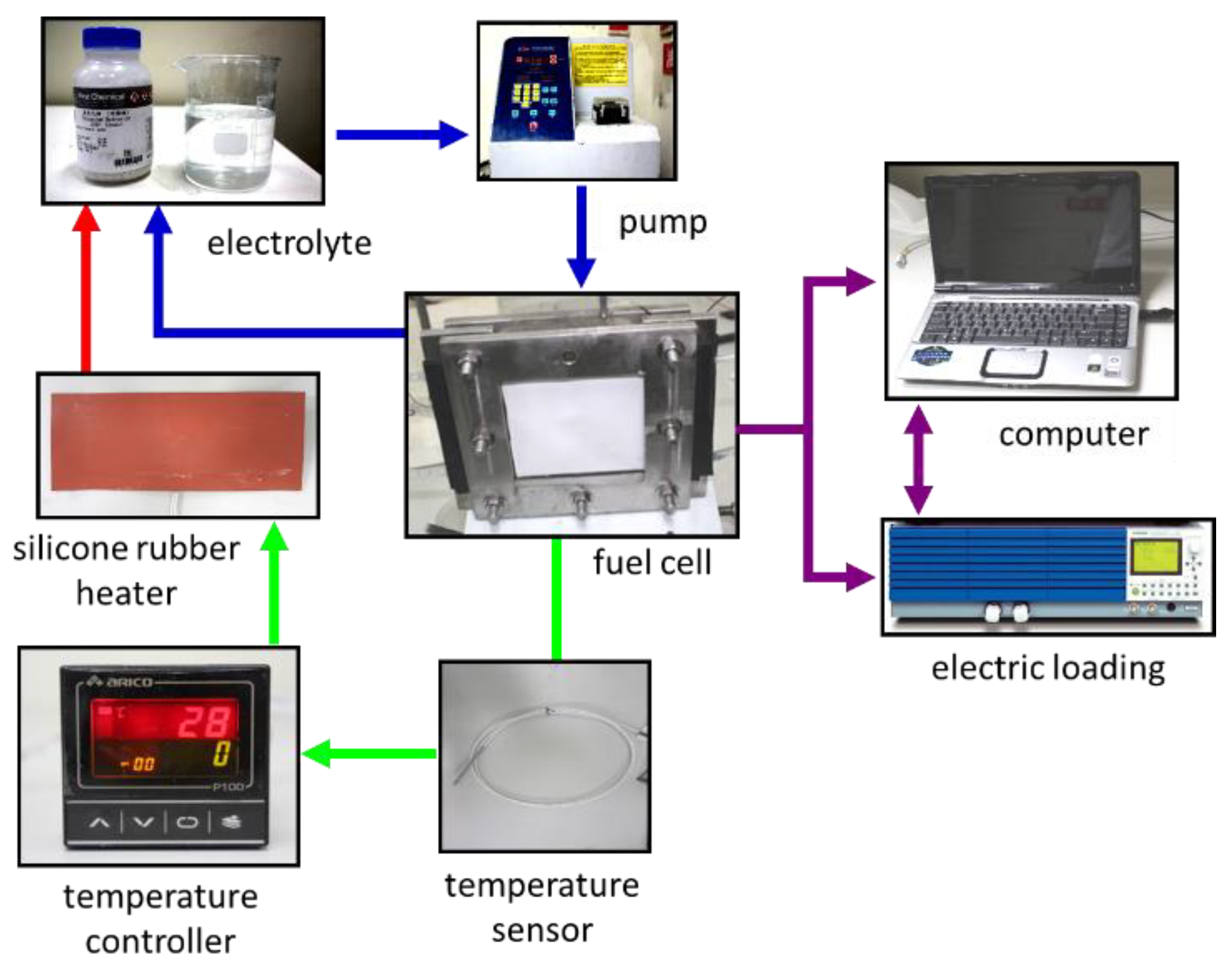
Figure 2.
(a) Schematic representation of the Zn plate fuel single cell. (b) Photograph of the fuel cell.
Figure 2.
(a) Schematic representation of the Zn plate fuel single cell. (b) Photograph of the fuel cell.
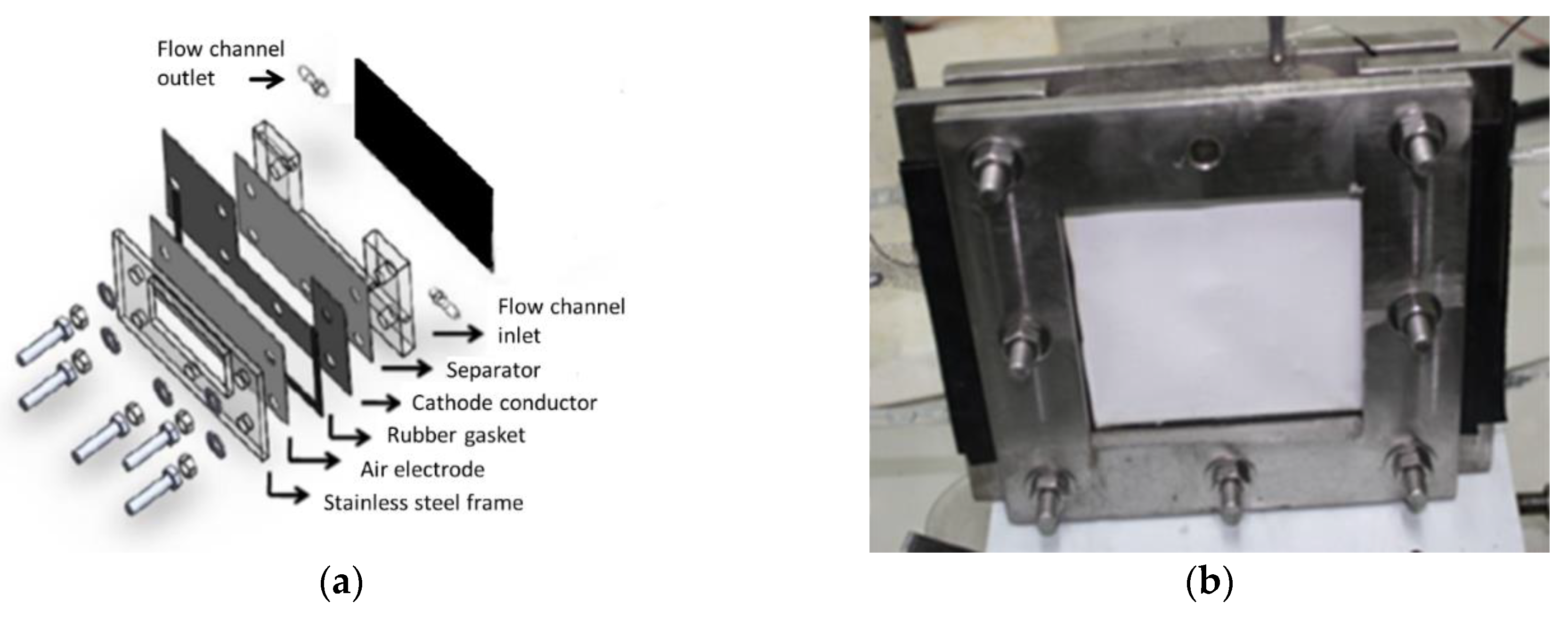
Figure 3.
(a) Polarization curve at various potassium hydroxide (KOH) concentration. (b) Current density production with respect to KOH concentration.
Figure 3.
(a) Polarization curve at various potassium hydroxide (KOH) concentration. (b) Current density production with respect to KOH concentration.
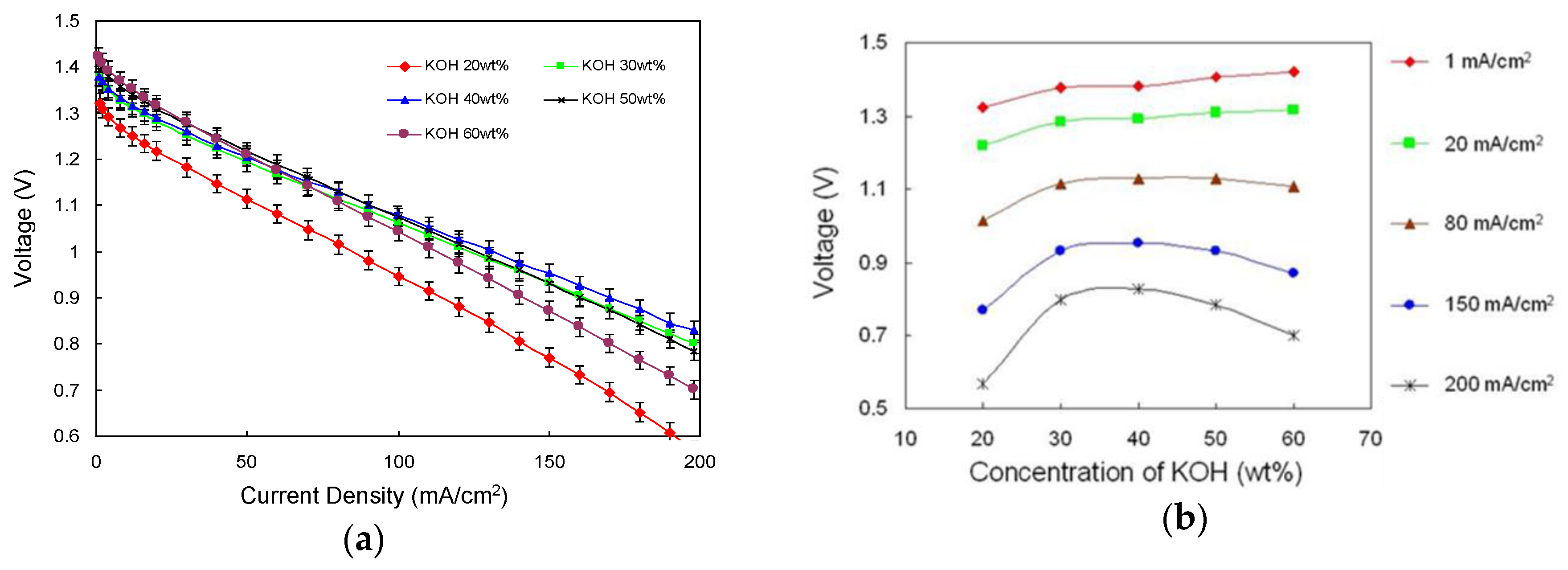
Figure 4.
(a) Polarization curve at different electrolyte temperatures. (b) Voltage production with respect to electrolyte concentration and temperature.
Figure 4.
(a) Polarization curve at different electrolyte temperatures. (b) Voltage production with respect to electrolyte concentration and temperature.
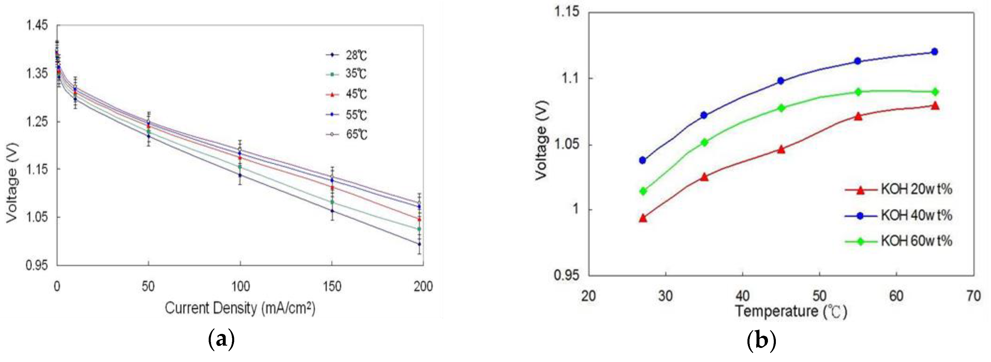
Figure 5.
(a) Polarization curve at different electrolyte flow velocity values. (b) Voltage and current density production in terms of electrolyte flow velocity.
Figure 5.
(a) Polarization curve at different electrolyte flow velocity values. (b) Voltage and current density production in terms of electrolyte flow velocity.
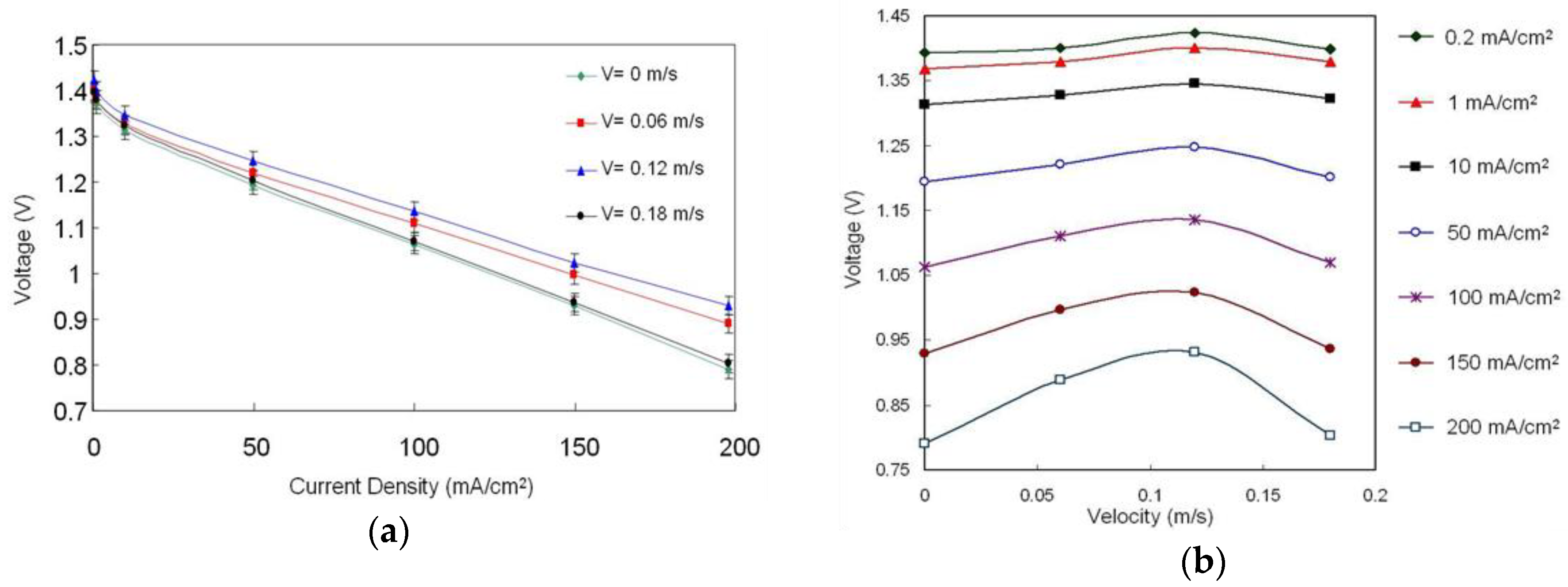
Figure 6.
(a) Anode current collectors with different grid shapes and surface areas. (b) Power production in zinc (Zn)-air fuel cells (ZAFCs) in terms of current collectors.
Figure 6.
(a) Anode current collectors with different grid shapes and surface areas. (b) Power production in zinc (Zn)-air fuel cells (ZAFCs) in terms of current collectors.
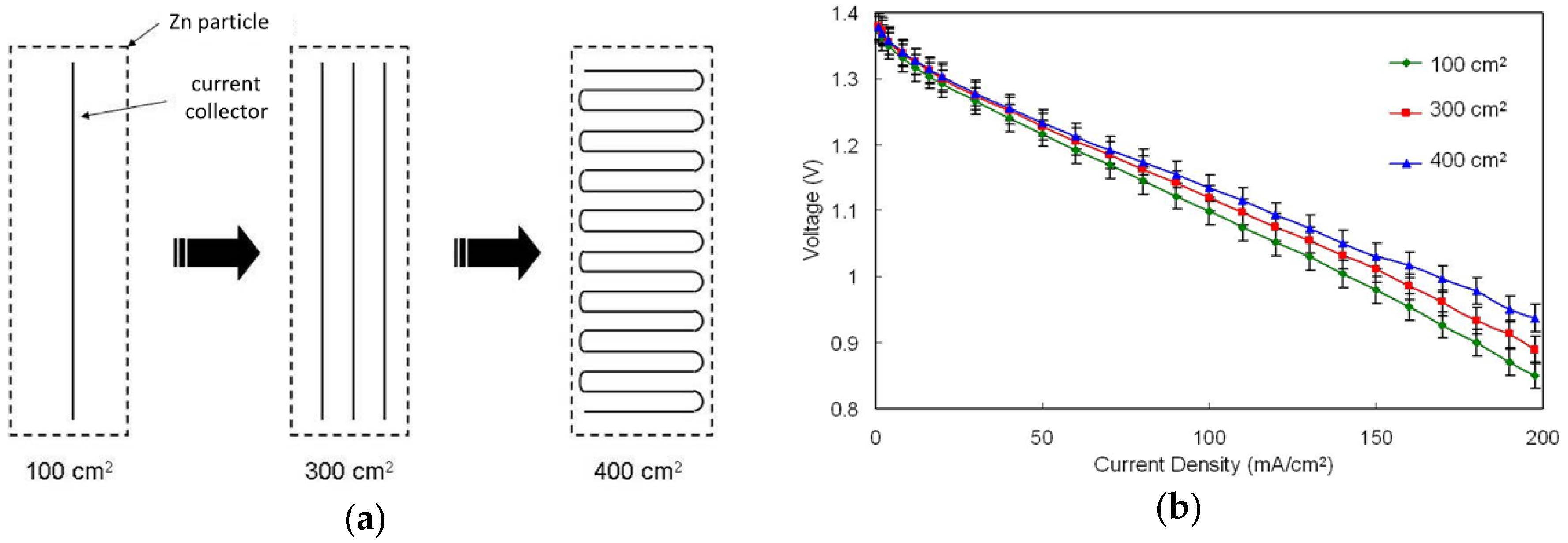
Figure 7.
Power performance of the ZAFCs in terms of air-cathode electrode conductive material.
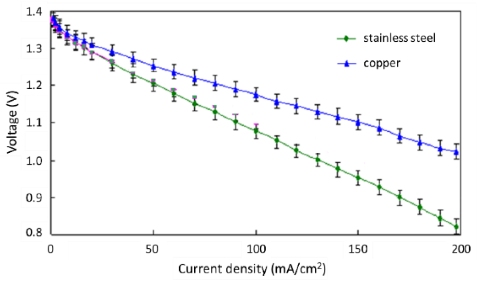
Figure 8.
(a) Anode current collectors with different grid shapes and surface areas. (b) Power production in ZAFCs in terms of current collectors.
Figure 8.
(a) Anode current collectors with different grid shapes and surface areas. (b) Power production in ZAFCs in terms of current collectors.

© 2019 by the authors. Licensee MDPI, Basel, Switzerland. This article is an open access article distributed under the terms and conditions of the Creative Commons Attribution (CC BY) license (http://creativecommons.org/licenses/by/4.0/).
Share and Cite
MDPI and ACS Style
Sangeetha, T.; Chen, P.-T.; Cheng, W.-F.; Yan, W.-M.; Huang, K.D. Optimization of the Electrolyte Parameters and Components in Zinc Particle Fuel Cells. Energies 2019, 12, 1090. https://doi.org/10.3390/en12061090
AMA Style
Sangeetha T, Chen P-T, Cheng W-F, Yan W-M, Huang KD. Optimization of the Electrolyte Parameters and Components in Zinc Particle Fuel Cells. Energies. 2019; 12(6):1090. https://doi.org/10.3390/en12061090
Chicago/Turabian StyleSangeetha, Thangavel, Po-Tuan Chen, Wu-Fu Cheng, Wei-Mon Yan, and K. David Huang. 2019. "Optimization of the Electrolyte Parameters and Components in Zinc Particle Fuel Cells" Energies 12, no. 6: 1090. https://doi.org/10.3390/en12061090
Note that from the first issue of 2016, this journal uses article numbers instead of page numbers. See further details here.