Calculation and Analysis of Rotor Thermal Static Field for Inter-Turn Short Circuit of Large Hydro-Generator Excitation Winding


State Key Laboratory of Alternate Electrical Power System with Renewable Energy Sources, North China Electric Power University, Baoding 071003, China
*
Author to whom correspondence should be addressed.
Energies 2019, 12(7), 1252; https://doi.org/10.3390/en12071252
Submission received: 1 March 2019
/
Revised: 18 March 2019
/
Accepted: 28 March 2019
/
Published: 1 April 2019
(This article belongs to the Section I: Energy Fundamentals and Conversion)
Abstract
:Rotor winding inter-turn short circuit a common fault in hydro-generators. This fault would change the temperature, stress, and other thermal fields of a rotor and threaten the safe operation of the generator. In this paper, the Three Gorges hydro-generator is taken as an example. Mathematical models of three-dimensional temperature field and thermal stress field of rotor magnetic poles are established based on heat transfer theory and solved by finite element method. The temperature field, thermal deformation, and thermal stress distribution of magnetic poles in rotor winding inter-turn short circuit are calculated. On the basis of the calculation, the effects of the different turn numbers and positions of short circuit on the temperature, thermal deformation, and thermal stress of rotor magnetic poles are further studied. It is concluded that the thermal stress of the winding adjacent to the shorted turn would decrease, the thermal stress of the winding farther away from the shorted winding would increase, and so on. The results of this paper can provide references for inter-turn short circuit fault diagnosis and lay a foundation for the further studies of related faults.
1. Introduction
Rotor winding inter-turn short circuit a common fault in hydro-generators. For most hydro-generators, rotor inter-turn short circuit faults have occurred or exist [1,2]. With increasing single unit capacity, the temperature, stress, and other changes in the internal structure of the hydro-generator are valued. When inter-turn short circuit occurs in the large hydro-generator rotor winding, the effective turns of the excitation winding decrease and the excitation current changes. These would change the temperature distribution of the rotor magnetic poles, and then affect the stress distribution of the rotor magnetic poles [3,4]. The unbalanced thermal stress of the magnetic poles may further enlarge the inter-turn short circuit fault and even threaten the safe operation of the generator unit. Therefore, it is of great significance to analyze the temperature field and thermal stress of excitation winding inter-turn short circuit fault of the large hydro-generator, which can provide a theoretical basis for related fault detection and treatment of the hydro-generator.
At present, many scholars have made contributions to studies on the temperature fields of motors and generators. Reference [5] studied stator main insulation temperature fields of air-cooled turbo-generators after main insulation shelling. The main insulation position of maximum temperature drops and the temperature distribution of the stator main insulation along the circumference and the axial direction were analyzed. Reference [6] calculated and analyzed the three-dimensional temperature field of an axial-radial flux-type permanent magnet synchronous motor. Reference [7] studied the effect of the terminal ventilation structure changes on the end temperature distribution in the turbo-generator unit. The 3-D transient electromagnetic field in the turbo-generator end was calculated, and the eddy current losses of the end parts were gained by the finite-element method. In reference [8], a two-dimensional mathematical model and boundary conditions were established to simulate the heat transfer and turbulent flow in the rotor body and ventilation duct. Reference [9] studied influence of rectifiers on high-speed permanent magnet generator electromagnetic and temperature fields in distributed power generation systems. Stator core losses and rotor eddy current losses were analyzed comparatively, and the influence of the converter on the generator power factor was further studied. Reference [10] calculated the conjugate heat transfer in turbulent flow within one coupled rotor model of a 250-MW hydro-generator. Reference [11] used FEM to calculate the 3D transient electromagnetic field in the air-cooled turbo-generator end and the eddy current losses of the end parts. The influence of the changed end ventilation structures on the temperature distribution of the end parts is obtained. Reference [12] calculated heat transfer coefficients and temperature fields of air-cooled large hydro-generator rotor excitation winding. In reference [13], the influence of rotor radial ventilation ducts number on temperature distribution of rotor excitation winding and fluid flow state between two poles of a fully air-cooled hydro-generator was calculated. Reference [14] calculated the temperature field and thermal stress of excitation winding inter-turn short circuit faults in turbo-generators. The temperature field and thermal stress were analyzed to provide characteristic parameters for inter-turn short circuit fault diagnosis of turbo-generators. Reference [15] studied the three-dimensional temperature fields in inter-turn short circuit of switched reluctance motors by using thermal signature. This paper analyzed the changes of motor temperature fields caused by winding inter-turn short circuits, and diagnosed the inter-turn short circuit faults by using the temperature changes of some parts. Reference [16] used thermal imaging techniques to analyze hydro-generator temperature fields and related efficiency.
Through the analysis of the above references, the studies mainly focused on the temperature field under the normal operation of the generator. Temperature and thermal stress field distribution, as characteristics of the inter-turn short circuit faults of hydro-generators, have seldom been studied. The temperature field results of this paper can provide reference for the diagnosis of inter-turn short circuits of hydro-generators, as mentioned in the reference [15,16]. In terms of thermal stress, some normal windings will have stress increase when inter-turn short circuit occurs. These stress increases may lead to new insulation damage and faults. Researching thermal static fields provides a new approach to inter-turn short circuit fault diagnosis. It can realize the joint diagnosis of multi fault characteristics and improve the accuracy of diagnosis. This paper establishes the calculation models of temperature field and thermal stress field of hydro-generator rotor magnetic poles based on finite element theory, heat transfer theory, and structural mechanics theory. Taking the 778 MW hydro-generator on the right bank of the Three Gorges Hydropower Station as an example, the paper calculates the various fields of the magnetic poles in the excitation winding inter-turn short circuit fault by using ANSYS software, respectively study the effects of different positions and turn numbers of the excitation winding inter-turn short circuit on the temperature field, thermal deformation, and thermal stress of various parts of the fault magnetic poles. When the short circuit occurs near the pole shoe and the pigeon tail end of the excitation winding, the effect on the distribution of the whole temperature field of the magnetic pole is relatively small, and the maximum temperature changes slightly. Through calculation and analysis, many conclusions of the thermal static structure are obtained under different inter-turn short circuit conditions.
2. Establishment of Solving Model
2.1. Heat Transfer Theory
The three-dimensional heat conduction equation of an object in steady state is [11]:
Equation (1) is a mixed boundary value calculation, and the corresponding functional J is:
where T is the temperature of the object; V is the temperature solution domain; Tf is the temperature of the surrounding air; λx, λy,, λz are thermal conductivities of the object in x-, y-, z-directions respectively; qv is the heat source density, here the loss caused by the generator rotor; S1 and S2 are the second and the third kind of boundary surfaces respectively, here the adiabatic surface and the radiating surface; α is a convection heat transfer coefficient.
The finite element model of three-dimensional temperature field of the object can be obtained by discretizing Equation (3)
where T is the temperature matrix in the solution domain; K is the total coefficient matrix; F is the total right end vector matrix. After solving the parameters in the Equation (3), the temperature of all the nodes can be obtained.
2.2. Thermal Stress Theory
According to the current thermal stress theory, the total strain of the element is superposed by two parts of changes. One part is caused by temperature change, and the other part by stress change [17]. Then, Hook’s law of elastic mechanics is extended to the equation containing thermal strain and thermal stress as
where E is the elastic modulus of the object; t is the temperature variations; ξ is the linear expansion coefficient; G is the shear elastic modulus; μ is the Poisson coefficient ratio; Θ is the volume stress; e is the volume strain. εx, εy, εz are respectively the strains in x-, y-, z- direction; σx, σy, σz are respectively the normal stresses in x-, y-, z- direction; γxy, γyz, γxz are respectively the shear strains of xy, yz, xz surfaces; τxy, τyz, τxz are respectively the shear stresses of xy, yz, xz surfaces. A generalized equation of stress expressed by strain and temperature difference can be obtained by substituting (6) and (7) into (4) and (5) as:
There are more unknowns than equations in the above equations. In order to obtain the unique solution, the coordination equation representing the inherent relationship between stress and strain and the displacement equation for eliminating the displacement component are needed.
The coordination equation is:
The solution of the thermodynamic elastic equation on the surface of the object shall also satisfy the following boundary conditions:
where are respectively components on the surfaces x, y, z of the element; l, m, n are respectively the cosines along the normal direction of the boundary surfaces. According to the above equations, the stress of the element can be calculated.
2.3. Physical Model
This paper establishes a physical model, taking the 778 MW hydro-generator rotor magnetic poles on the right bank of Three Gorges Hydropower Plant as the example. The main parameters of the hydro-generator and its rotor are listed in Table 1.
There are many magnetic poles of the Three Gorges hydro-generator, and the rotor magnetic pole structure is relatively complex. Limited by the calculation capacity of the simulation equipment, in order to ensure the accurate calculation of magnetic pole thermal stress, it is necessary to reasonably simplify the rotor solution domain and establish the calculation model of a single magnetic pole, shown in Figure 1, where the assumptions are as follows [18,19,20,21,22].
- (1)
- The calculation model for one magnetic pole of the hydro-generator is established given that all rotor magnetic poles and wind paths of the hydro-generator are symmetrical.
- (2)
- The average values of air temperature are taken on the windward side and the leeward side of the excitation winding respectively.
- (3)
- The complex interface of the actual excitation coil is simplified to right angle connection.
- (4)
- The rotor winding insulation of the Three Gorges hydro-generator is Nomex paper. The heat conduction coefficient about the insulation of excitation winding is set to the same as Nomex paper. The insulation between the winding and core is set to an equivalent heat conduction coefficient.
- (5)
- The heat conduction coefficient of the rotor core is anisotropic in the temperature calculation.
- (6)
- The inter-turn short circuit cases in this paper all belong to a metallic short circuit. In the case of a metallic short circuit, there is no direct current in the shorted copper coil, and there is no copper loss at the short circuit point, and the current flows directly through the short circuit point.
- (7)
- The stress, strain, displacement, and other parameters generated by the load are all continuous functions in the structure involved in the magnetic pole model.
- (8)
- Each part of the magnetic pole is completely elastic, that is, the deformation of the object under external load can completely recover after unloading without any residual deformation.
Based on the above assumptions, the rotor magnetic pole model is established and subdivided. In the process of subdivision, the inter-turn short circuit fault of the magnetic pole excitation winding is calculated. Therefore, it is necessary to intensively subdivide the magnetic pole winding area. The subdivision of the solution domain is shown in Figure 2.
3. Determination of Boundary Conditions and Related Parameters
3.1. Boundary Conditions of Temperature Field
(1) The boundary face below the magnetic pole is an adiabatic surface. (2) The surfaces of the excitation winding and the pole shoes, and the boundary surfaces of its windward and leeward sides are all heat radiating surfaces. (3) The left side of the magnetic pole in Figure 1 is a rotating windward side, the front is an axial ventilated windward side, and the opposite side is a leeward side.
3.2. Boundary Conditions of Thermal Stress Field
In this paper, the thermal stress is calculated by thermal structure coupling analysis. The elastic modulus, Poisson ratio, thermal expansion coefficient, specific heat capacity, and thermal conductivity should be defined for magnetic pole structure material [23,24]. The International System of Units is used in the material properties.
There are four insulating plates near the pole shoe end of the rotor magnetic pole. There are insulating plates and steel support plates at the four corners of the coil near the pigeon tail end of the magnetic pole. These are shown in Figure 3. These structures can be equivalent by exerting stress at their positions. For example, the structure of the pigeon tail can be fixedly supported in the software according to the actual situation.
3.3. Rotor Loss of Hydro-Generator
There are many kinds of heat sources in the large hydro-generator rotor, mainly including copper losses of excitation windings and stray losses of damping windings. In order to ensure the accuracy of the model and the calculation, the following losses are considered:
- (1)
- The stray losses caused by the magnetomotive force harmonic waves of the stator winding in the damping winding [23].where ; ; ; . p is the number of generator pole pairs; is the number of damping strips; lB is length of a damping strip; CB is the ratio of resistance coefficient of the damping strip to copper resistance coefficient; AB is the section area of the damping strip; dB is diameter of the damping strip; δ is gap length; τ is pole pitch; kδ is total air gap coefficient; Fδ is the magnetic potential drop of the air gap; t2 is the pitch of the rotor damping strip; hn2 is the notch height of the damping slot; bn2 is the notch width of the damping slot; δ′ is the length of the calculation air gap; xad is the reactive reactance of the longitudinal axis armature.
- (2)
- Surface losses of pole shoes at no-load rated voltagewhere ∆ is the thickness of the magnetic plate; kδ1 is the air gap coefficient of the stator slot; Bδ is average magnetic density of air gaps within pole shoes; t1 is stator pitch; Ap is the calculation area of pole shoe surface.
3.4. Heat Transfer Coefficients of the Magnetic Poles and Excitation Windings of the Hydro-Generator
The rotor structure of large hydro-generator is relatively complicated, and the process of air flow in the air gaps and between rotor magnetic poles caused by the rotating rotor magnetic poles with radiating fins is also very complicated. In order to solve the difficult problem in calculating the surface heat transfer coefficient of the rotor excitation winding, the method of empirical equations is used [25].
For the rotor magnetic pole with radiating fins of the hydro-generator, the heat transfer coefficient of the rotating coil with radiating fins is:
where vp is inter-pole wind speed. The heat transfer rate of the windward sides is different from that of the leeward side, and the heat transfer coefficient of the rotor winding will change as follows.
The windward side has higher wind speed and better heat radiation. Therefore, for the rotor windward side the coefficient K is about 1.1. The heat radiation of the leeward side is poor, so for the rotor leeward side the coefficient K is about 0.9. The axial ventilation and heat radiation of an air-cooled generator are considered. Therefore, there are also windward and leeward sides in the axial direction. Their heat transfer coefficients are also expressed in the Equations (17) and (18).
3.5. Effect of Rotor Winding Inter-Turn Short Circuit Current
According to the assumed conditions in Section 2.3 (6), when the excitation voltage is invariant pre and post inter-turn fault of excitation winding, the excitation current will increase with the increase of the number of short circuit turns. The temperature and stress field of the rotor magnetic poles would be affected differently.
The harmonic circulation current is generated in the stator winding when the excitation winding short circuit and then the corresponding air gap magnetic field is generated, and alternating current is induced in the excitation winding. This current is small, and its effect on temperature can be neglected.
4. Calculation of Temperature Field in Rotor Winding Inter-Turn Short Circuit
4.1. Temperature Field of Rotor Magnetic Pole under Normal Excitation Winding
The temperature field of the rotor magnetic pole without excitation winding inter-turn short circuit is first calculated, as shown in Figure 4. Figure 4 is based on the positive direction of the X-, Y-, Z-axis. The rotation direction of rotor pole is from right to left, that is, the opposite direction of X-axis. In this paper, the excitation turns from the pole shoe end to the pigeon tail end are numbered 1 to 14.
The calculated normal temperature of the magnetic pole is basically the same as the actual temperature measured at the monitoring points in [26]. As shown in Figure 5, the test point is on the excitation winding below the magnetic pole. The results of comparison are listed in Table 2, proving the correctness of the calculation model.
4.2. Effect of Inter-Turn Short Circuit on Temperature of Excitation Winding
The temperature field in short circuit of each turn of the rotor pole is calculated respectively. As shown in Figure 6, the temperature fields of the magnetic pole are respectively in the 6th turn and the 12th turn shorted. Figure 7 shows the temperature of the excitation winding when each turn is respectively shorted.
According to Figure 6 and Figure 7, the temperature of the short circuit winding is lowered. The reason is that when metallic short circuit occurs in the rotor winding, the current flows through the short circuit point. The copper loss in the short circuit turn is zero because the shorted turn current is zero. The inter-turn short circuit causes increase of excitation current, which leads to the rising trend of pole temperature. However, the inter-turn short circuit on one pole is a very small fault, and the excitation current increases slightly. The calculation shows that the temperature is mainly affected by the reduction of copper losses.
When the shorted turn is in the middle part, its temperature slightly drops affected by the adjacent excitation windings heating. When the shorted turn is close to the magnetic pole surface and the magnet yoke, the temperature falls greatly because of the distance from other excitation windings and the larger heat radiation area. The shorted turn has great influence on the temperature of two adjacent turns of the winding. The temperature of the shorted turn would be affected by the surrounding normal excitation windings.
4.3. Effect of Inter-Turn Short Circuit on the Whole Temperature Field of Magnetic Pole
The whole temperature field of the magnetic pole would also be affected when an inter-turn short circuit occurs in the rotor excitation winding. The maximum temperature and the lowest temperature of the magnetic pole can reflect the whole temperature changes of the magnetic pole. The calculated results are shown in Figure 8.
The figure shows the changes of the maximum and the minimum temperatures of magnetic pole when the number of turns and the position of inter-turn short circuit of the rotor excitation winding change. The shorted turn number in Figure 8 is 0, indicating no inter-turn short circuit in the winding. When a two-turn short circuit occurs, the number near the pole shoe represents the shorted turn number. If the shorted turn is 4, two-turns mean that turns 4 and 5 are shorted. In a three-turn short circuit, the middle turn number is used as the shorted turn number. If the shorted turn is 4, three-turns mean that turns 3, 4, and 5 are shorted. According to the analysis of Figure 8, the temperature of rotor magnetic pole would be affected by the different positions of inter-turn short circuit in the rotor excitation winding. The short circuit of the excitation windings near the pole shoe and pigeon tail end has less influence on the maximum temperature. The short circuit of No.6–No.8 turns in the middle part has the greatest influence on the maximum temperature, with the largest temperature drop in the magnetic pole. Given the calculation results in Figure 7 and Figure 8, when the inter-turn short circuit occurs in the excitation winding in the middle of the magnetic pole, the excitation winding with high temperature stops heating, which directly affects the high temperature area of the magnetic pole. Combined with the conclusion in the above section, the whole temperature of the magnetic pole is greatly affected by the short circuit of the central excitation turn.
The short circuit in the central turns of the excitation winding of the magnetic pole has little effect on the minimum temperature of the magnetic pole, while the short circuit in the excitation windings on both sides of the magnetic pole has relatively large effect on the minimum temperature. As shown in Figure 8, when the 1st and 13th turns are shorted, there will be a decrease in the temperature. Different from the effect of inter-turn short circuit on the maximum temperature, inter-turn short circuit will change the location of the lowest temperature of the magnetic pole and then affect the lowest temperature.
Figure 9 shows the temperature field where two and three shorted turns occur in the middle of the excitation winding. According to the comparison and analysis between Figure 8 and Figure 9, the effects of the changes of the number of shorted turns in the rotor magnetic pole excitation winding on the temperature field in magnetic pole are similar, but the effect of a short circuit on the temperature field will be greater with an increasing number of short circuit turns.
5. Thermal Deformation of Rotor Winding Inter-Turn Short Circuit
Because of different thermal expansion coefficients between the rotor magnetic pole core and the excitation winding, the thermal deformations would be different with the change of the magnetic pole temperature field after the short circuit, which would affect the rotor magnetic pole structure and the reliability of the generator.
Figure 10 shows the thermal deformation, in the international unit of length, of the rotor magnetic pole in normal condition. Figure 11 shows the thermal deformation of the magnetic pole with the 6th to 8th turns shorted of the excitation winding. According to the calculation, the inter-turn short circuit in the rotor central winding would reduce the whole deformation of the magnetic pole, where the thermal deformation of the shorted turns decreases more. With the increasing number of shorted turns, the whole deformation of the magnetic pole decreases, but the non-uniformity of winding deformation is aggravated.
Figure 12 shows the relationship between the thermal deformation and the short circuit position of some turns at the front end of the excitation winding. From Figure 12, it can be seen that the thermal deformation first decreases and then rises with the short circuit positions from the pole shoe end to the pigeon tail end, indicating small thermal deformation of excitation windings when the short circuit occurs between that fifth and seventh turns. The thermal deformation of the second, fourth, and sixth turns would be larger than the normal ones when the short circuit occurs near the pigeon tail end of the magnetic pole.
In summary, the inter-turn short circuit fault in the excitation winding would increase the imbalance of the thermal deformation of the excitation winding, decrease the thermal deformation of the shorted turn, and increase the thermal deformation of the excitation winding farther away from the shorted turn.
6. Calculation of Thermal Stress in Rotor Winding Inter-Turn Short Circuit
The thermal stress calculated in this section is mainly equivalent stress. According to the second strength theory of material mechanics, the main factor causing material failure is the maximum tensile strain. Regardless of the state, the material is fractured as long as the maximum tensile strain reaches the maximum strain value of the material at tensile fracture. A comprehensive value of the principal stress is formally compared with the allowable tensile compression stress in the uniaxial direction of the material, and this comprehensive value is the equivalent stress.
6.1. Effect of the Number of Short Circuit Turns on Thermal Stress Distribution
The stress distribution of the rotor pole under the normal conditions is shown in Figure 13. The stress distribution is balanced, with small stress at the two ends of the magnetic pole and large stress in the middle of the magnetic pole.
The influence of different numbers of shorted turns on the thermal stress distribution of the magnetic pole is calculated with the seventh turn of the excitation winding as the center of the shorted turns. Figure 14 shows the section of the thermal stress of the magnetic pole along the central axis when the winding is short circuited. In the figure, (a) and (b) respectively show one- and three-turn short circuits. Figure 15 shows the changes of thermal stress of some excitation windings when shorted turns are from 0 to 6.
From the calculation results, it can be seen that: (1) The thermal stress in the central part of the shorted turn is slightly larger than the normal when a shorted turn occurs in the rotor, that is, the seventh turn of the excitation winding is shorted, according to the comparison between Figure 14 and Figure 15. With the increasing number of shorted turns, the thermal stress of the seventh winding decreases gradually. This is because a shorted turn makes heating of the shorted turn reduce and the temperature drop. A certain temperature difference between the surrounding normal winding and it is generated and causes thermal stress to increase. The range of increasing thermal stress is larger than that of the decreasing thermal stress caused by decreasing temperature of the shorted turn. When the multiple turns are shorted, the range of decreasing thermal stress caused by decreasing temperature is larger, and thermal stress of the shorted turns decreases.
(2) From Figure 15, it can be seen that the thermal stress of the 2nd and 14th turns increases when an inter-turn fault occurs, but the thermal stress of the 14th turn decreases after a 5-turn short circuit of winding. The thermal stress of the 4th and 10th windings does not change much when the number of shorted turns is small. The thermal stress of the 4th turn increases and that of the 10th turn decreases when the number of shorted turns is larger. The thermal stress of the 6th turn decreases with the increasing number of shorted turns.
Thus, the thermal stress changes of adjacent normal windings can be obtained: the thermal stress of the winding farther away from the shorted winding, such as the 2nd turn and the 14th turn, would increase when inter-turn short circuit in the rotor; the thermal stress of the winding adjacent to the shorted turn would decrease; the thermal stress of the excitation winding between the above two has little change; but the thermal stress of the winding near the rotor magnetic pole shoe end tends to increase, and the thermal stress of the winding near the pigeon tail end tends to decrease.
(3) The distributions of the magnetic pole thermal stress components in X-, Y-, Z-direction are shown in Figure 16. 1-x in the figure indicates the thermal stress in X-direction in one turn short circuit. From the figure, it can be seen that there are positive and negative values of the stress in each component. According to the principle of thermal stress calculation, tensile stress and strain are positive, compressive stress and strain are negative.
From Figure 16, it can be seen that the larger tensile stress than that of the surrounding windings would appear in the shorted turn when inter-turn short circuit occurs in the excitation winding in X-direction, that is, in the rotor rotation direction. The tensile stress would increase with the increasing number of shorted turns and the scope of influence is gradually increasing. In the Y-direction—that is, the rotor radial direction—the stress change of the shorted turn is relatively small after an inter-turn short circuit occurs in the excitation winding. There are large compressive stresses on the excitation windings of two sides. In Z-direction—that is, the axial direction of generator rotor—there are large compressive stresses on the normal excitation windings. When the short circuit occurs in the excitation winding, there would be smaller stress in the shorted turns and larger compressive stress on the excitation windings of two sides. With the increasing number of shorted turns, a small tensile stress would appear in the shorted turns, and the compressive stress of the normal windings remains unchanged.
6.2. Effect of Inter-Turn Short Circuit Position on Thermal Stress Distribution
In this section, for different fault positions, the whole thermal stress changes of magnetic poles, the thermal stress of the short circuit windings, and the thermal stress of other excitation windings are calculated and analyzed with the example of three-turn short circuit in the excitation winding. The number of inter-turn short circuit positions in this section is the number of intermediate excitation windings in three-turn short circuit, consistent with 4.2. By calculation, the effect of the change of inter-turn short circuit position on the thermal stress distribution is as follows.
(1) Figure 17 shows the thermal stress distribution of the magnetic pole in the case of short circuit faults at three different locations in the three windings. Compared Figure 13 with Figure 17, it can be seen that the thermal stress of the structure at the pole shoe decreases and the thermal stress of the excitation winding at the pigeon tail end increases when the short circuit occurs near the magnetic pole shoe. The thermal stress of the winding near the pole shoe increases slightly when the short circuit occurs near the pigeon tail end.
(2) Table 3 lists the thermal stress of three-turn short circuit turns when the position of inter-turn short circuit changes. The layer in the table indicates the position of each turn among the three shorted turns, the upper-layer represents the turn closer to the pole shoe, and the lower-layer represents the turn closer to the pigeon tail end. For example, for a 2–4 turn short circuit, the second turn is the upper-layer turn, the third turn is the middle-layer turn, and the fourth turn is the lower-layer turn. In addition, ‘normal’ in the right column of Table 3 represents the thermal stress of the generator in the healthy condition.
From the analysis of Table 3, it can be seen that the thermal stress of short circuit turns is almost greater than 35 MPa when the short circuit occurs in the excitation windings in the middle of the magnetic pole, which is higher than the thermal stress at the pole shoe end and the pigeon tail end. The decrease range of thermal stress in short circuit turns is smaller than that in normal windings when the inter-turn short circuit fault occurs in the middle of the magnetic pole, and the decrease range of thermal stress is larger when the short circuit fault occurs at the magnetic pole shoe end and the pigeon tail end. In addition, it can be seen from Table 3 that the thermal stress of the upper-layer turn is greater than that of the lower-layer when the inter-turn short circuit is near the pole shoe end, and the lower-layer turn is basically larger than that of the upper layer when the inter-turn short circuit is near the pigeon tail end. This is also in accordance with the above law.
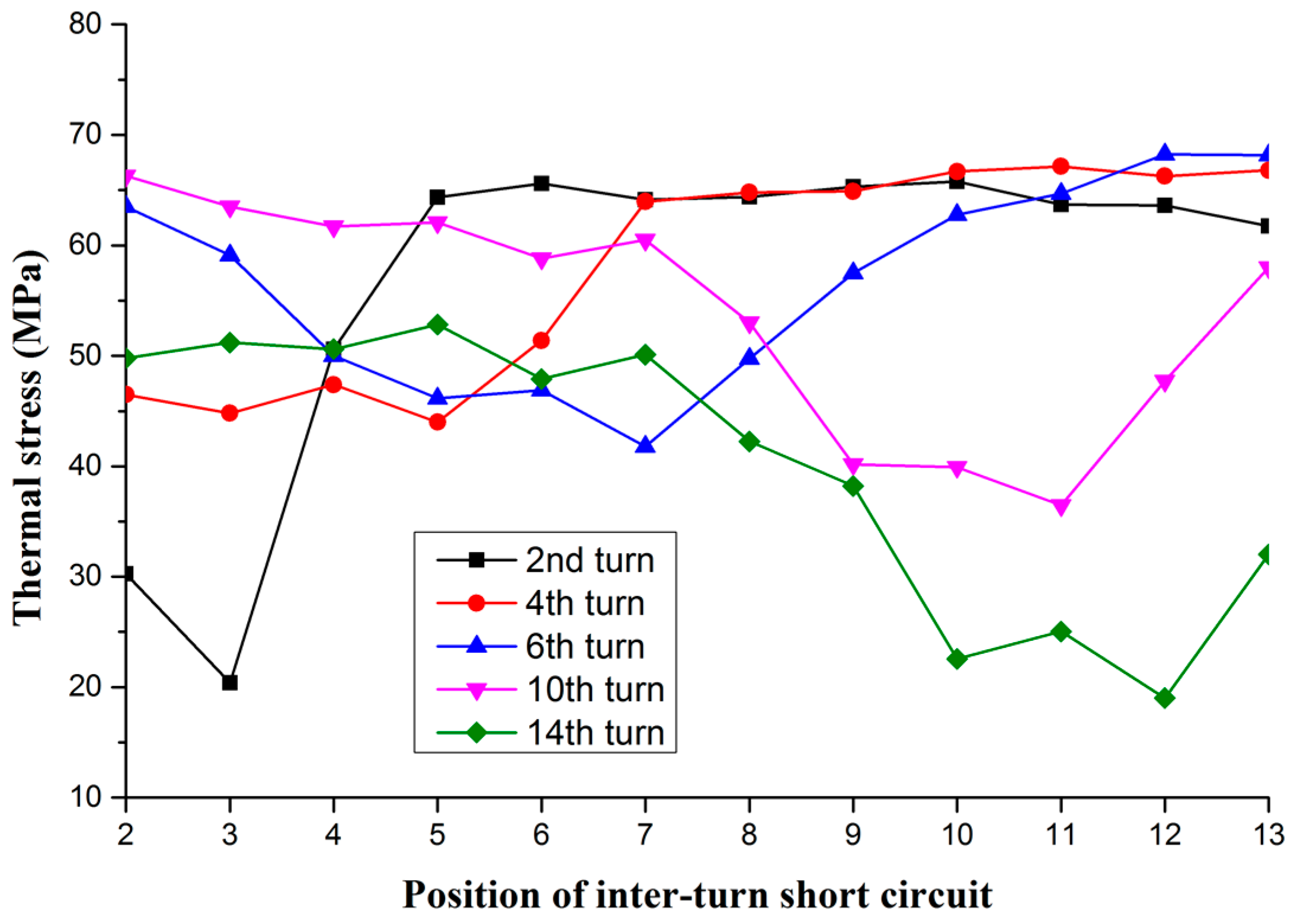
(3) Figure 18 shows the thermal stress of several specific excitation coils when the inter-turn short circuit position changes. As shown in Figure 18, each curve has a different degree of depression area, caused by the decrease of thermal stress during the inter-turn short circuit fault corresponding to the excitation winding. At the same time, the changes of thermal stress are different when the excitation winding is in the non-fault area. The thermal stress of the windings near the pole shoe end changes very little with the fault position when the fault occurs before the seventh turn, such as the second turn, and the fourth turn. The stress of the winding near the magnetic pole pigeon tail end changes relatively large when the fault occurs after the 7th turn, such as the 10th and 14th turns.
By comparing the thermal stresses in the fault of the five excitation windings in Figure 18 with their corresponding normal thermal stresses, we get the final result. The thermal stress of each excitation winding in short circuit in Figure 18 decreases, and the thermal stress increases when it is far from the short circuit area. The conclusion in 6.2 is proven by the analysis of thermal stress difference in that the thermal stress of the excitation winding far away from the short circuit turns increases.
7. Conclusions
The inter-turn short circuit faults of excitation winding will lead to changes in the thermal static field. The thermodynamic change of rotor magnetic pole is quite complicated, since it depends on the number and position of the shorted turns. The thermodynamics of magnetic pole in the case of inter-turn short circuit of rotor excitation windings of the hydro-generator on the right bank of Three Gorges is calculated and analyzed in detail, and the main conclusions on the changes of magnetic pole fields are obtained as follows.
- (1)
- When the short circuit occurs, the whole temperature of the magnetic pole decreases. The more shorted turns there are, the more obvious the temperature change is. Among them, when the inter-turn short circuit occurs in the middle winding of the magnetic pole, the distribution of the temperature fields of the surrounding excitation windings and magnetic poles is greatly affected. The maximum temperature of magnetic pole decreases greatly, and the lowest temperature and position remain basically unchanged. When the short circuit occurs near the pole shoe and the pigeon tail end of the excitation winding, the effect on the distribution of the whole temperature field of the magnetic pole is relatively small. The maximum temperature changes slightly. The lowest temperature decreases and the position of the lowest temperature point change accordingly. The diagnosis of inter-turn short circuit can be realized by monitoring the change of the rotor temperature.
- (2)
- With the increasing number of shorted turns, the whole thermal deformation of the magnetic pole decreases. The thermal deformation of the excitation winding far away from the short circuit turns would increase. At the same time, the changes of the excitation winding temperature result in the deformations in the excitation winding not being uniform.
- (3)
- When a turn short circuit occurs, the thermal stress of the shorted turn increases. When a multi-turn short circuit occurs, the thermal stress of the shorted turns decreases. The greater the number of shorted turns, the greater the reduction of thermal stress, in which larger tensile stress would occur in the shorted turns along the X-direction. The thermal stress of the shorted turn decreases by a small extent when the inter-turn short circuit fault occurs in the middle of the magnetic pole, and the thermal stress decreases greatly when it occurs at the pole shoe end and the pigeon tail end.
The thermal stress of the winding adjacent to the shorted turn decreases when short circuit fault occurs in the rotor. The thermal stress of the winding farther away from the shorted winding would increase, and the thermal stress of the excitation winding between the above two would slightly change.
To sum up, the work in this paper can provide basis for deeper studies of the hydro-generator inter-turn short circuit fault and provide new feature for inter-turn short circuit fault diagnosis.
Author Contributions
L.W. and J.L. initiated the idea of the rotor thermal static field for inter-turn short circuit of large hydro-generator excitation winding; L.W. and J.L. analyzed the data; L.W. wrote the calculation program; L.W. wrote the paper; and J.L. proofread the paper.
Funding
This research was funded by the China Scholarship Council (201706735002) and Fundamental Research Funds for the Central Universities (2017XS115).
Conflicts of Interest
The authors declare no conflict of interest.
References
- Wang, L.; Li, Y.; Li, J. Diagnosis of inter-turn short circuit of synchronous generator rotor winding based on volterra kernel identification. Energies 2018, 11, 2524. [Google Scholar] [CrossRef]
- Li, Y.; Wang, L.; Ma, M. Diagnosis of rotor winding inter-turn short circuit of hydro-generator based on no-load curve reverse calculation. IEEJ Trans. Electr. Electron. Eng. 2019, 14, 130–137. [Google Scholar] [CrossRef]
- Wu, Y.; Li, Y. Diagnosis of rotor winding interturn short circuit in turbine generators using virtual power. IEEE Trans. Energy Convers. 2015, 30, 183–188. [Google Scholar]
- Hao, L.; Wu, J.; Zhou, Y. Theoretical analysis and calculation model of the electromagnetic torque of nonsalient-pole synchronous machines with interturn short circuit in field windings. IEEE Trans. Energy Convers. 2015, 30, 110–121. [Google Scholar] [CrossRef]
- Li, W.; Li, Y.; Su, Y.; Wang, P.; Liu, W. Research on stator main insulation temperature field of air-cooled turbo-generator after main insulation shelling. Energies 2018, 11, 1101. [Google Scholar] [CrossRef]
- Li, D.; Wen, Y.; Li, W.; Feng, B.; Cao, J. Three-dimensional temperature field calculation and analysis of an axial-radial flux-type permanent magnet synchronous motor. Energies 2018, 11, 1208. [Google Scholar] [CrossRef]
- Li, W.; Han, J.; Huo, F.; Zhou, X.; Zhang, Y.; Li, Y. Influence of the end ventilation structure change on the temperature distribution in the end region of large water–hydrogen–hydrogen cooled turbogenerator. IEEE Trans. Energy Convers. 2013, 28, 278–288. [Google Scholar]
- Lu, Y.; Li, W.; Ma, X.; Jin, H. Numerical simulation of temperature field in rotor of large turbo generator with air-coolant. Proc. CSEE 2007, 27, 7–13. [Google Scholar]
- Qiu, H.; Yi, R.; Li, W.; Jin, N. Influence of rectifiers on high-speed permanent magnet generator electromagnetic and temperature fields in distributed power generation systems. IEEE Trans. Energy Convers. 2015, 30, 655–662. [Google Scholar]
- Li, W.; Guan, C.; Chen, Y. Influence of rotation on rotor fluid and temperature distribution in a large air-cooled hydrogenerator. IEEE Trans. Energy Convers. 2013, 28, 117–124. [Google Scholar]
- Wang, L.; Chen, W.; Tao, D.; Li, W.; Ge, B. Research on the impact of screen properties on eddy current and flux in end region of a large air-cooled turbo-generator. IEEE Trans. Energy Convers 2016, 31, 218–227. [Google Scholar] [CrossRef]
- Li, W.; Zhang, Y.; Chen, Y. Calculation and analysis of heat transfer coefficients and temperature fields of air-cooled large hydro-generator rotor excitation windings. IEEE Trans. Energy Convers. 2011, 26, 946–952. [Google Scholar]
- Li, W.; Li, D.; Li, J. Influence of rotor radial ventilation ducts number on temperature distribution of rotor excitation winding and fluid flow state between two poles of a fully air-cooled hydro-generator. IEEE Trans. Ind. Electron. 2017, 64, 3767–3775. [Google Scholar] [CrossRef]
- Ma, M.; Li, Y.; Wu, Y.; Dong, C. Multifield calculation and analysis of excitation winding interturn short circuit fault in turbo-generator. Energies 2018, 10, 2626. [Google Scholar] [CrossRef]
- Carlos, C.; Yinan, L.; Lizon, M. Thermal signature analysis of an 8/6 switched reluctance motor under inter-turn short circuit fault. In Proceedings of the IEEE International Conference on Industrial Technology (ICIT), Lyon, France, 20–22 February 2018; pp. 1859–1864. [Google Scholar]
- Da Costa Bortoni, E.; Siniscalchi, R.T.; Jardini, J.A. Determination of hydro generator efficiency using infrared thermal imaging techniques. IEEE Trans. Energy Convers. 2011, 26, 1134–1139. [Google Scholar] [CrossRef]
- Ashtiani, C.N.; Lowther, D.A. Simulation of the transient and subtransient reactance of a large hydrogenerator by finite elements. IEEE Trans. Power App. Syst. 1984, PAS-103, 1788–1794. [Google Scholar] [CrossRef]
- Nathenson, R.D.; Cherepko, J.; Patel, M.R. Thermal stress analysis and design of the stator of a 300 MVA superconducting generator. IEEE Trans. Energy Convers. 1986, EC-1, 141–147. [Google Scholar] [CrossRef]
- Istad, M.; Runde, M.; Nysveen, A. A review of results from thermal cycling tests of hydrogenerator stator windings. IEEE Trans. Energy Convers. 2011, 26, 890–903. [Google Scholar] [CrossRef]
- Sharifi, E.; Jayaram, S.H.; Cherney, E.A. Analysis of thermal stresses in medium-voltage motor coils under repetitive fast pulse and high-frequency voltages. IEEE Trans. Dielectr. Electr. Insul. 2010, 17, 1378–1384. [Google Scholar] [CrossRef]
- Xie, Y.; Guo, J.; Chen, P.; Li, Z. Coupled fluid-thermal analysis for induction motors with broken bars operating under the rated load. Energies 2018, 11, 2024. [Google Scholar] [CrossRef]
- Wu, Y.; Ma, M.; Li, Y. A new detection coil capable of performing online diagnosis of excitation winding short circuits in steam-turbine generators. IEEE Trans. Energy Convers. 2018, 33, 106–115. [Google Scholar]
- Wu, Y.; Li, Y. Diagnosis of short circuit faults within turbogenerator excitation winding based on the expected electromotive force method. IEEE Trans. Energy Convers. 2016, 31, 706–713. [Google Scholar]
- Kim, J.K.; Kwak, S.Y.; Cho, S.M.; Jung, H.K.; Chung, T.K.; Jung, S.Y. Optimization of multilayer buried magnet synchronous machine combined with stress and thermal analysis. IEEE Trans. Magn. 2006, 42, 1023–1026. [Google Scholar]
- Chen, X. Electromagnetic Analysis and Calculation of Hydro Generator; China Water Conservancy and Hydropower Press: Beijing, China, 2011. [Google Scholar]
- Bi, C.; Hu, L.; Han, B. The online monitoring system of rotor temperature on three gorges hydro generator. Large Electr. Mach. Hydraul. Turbine 2008, 5, 1–4. [Google Scholar]
Figure 1.
Calculation model of rotor magnetic pole.

Figure 2.
Subdivision of rotor magnetic pole solution domain.
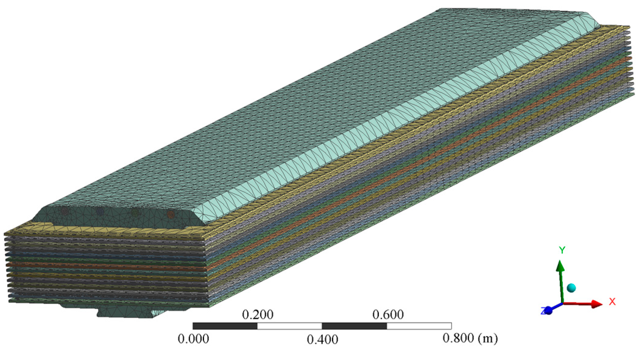
Figure 3.
Rotor magnetic pole structure (a) pole shoe; and (b) pigeon tail.
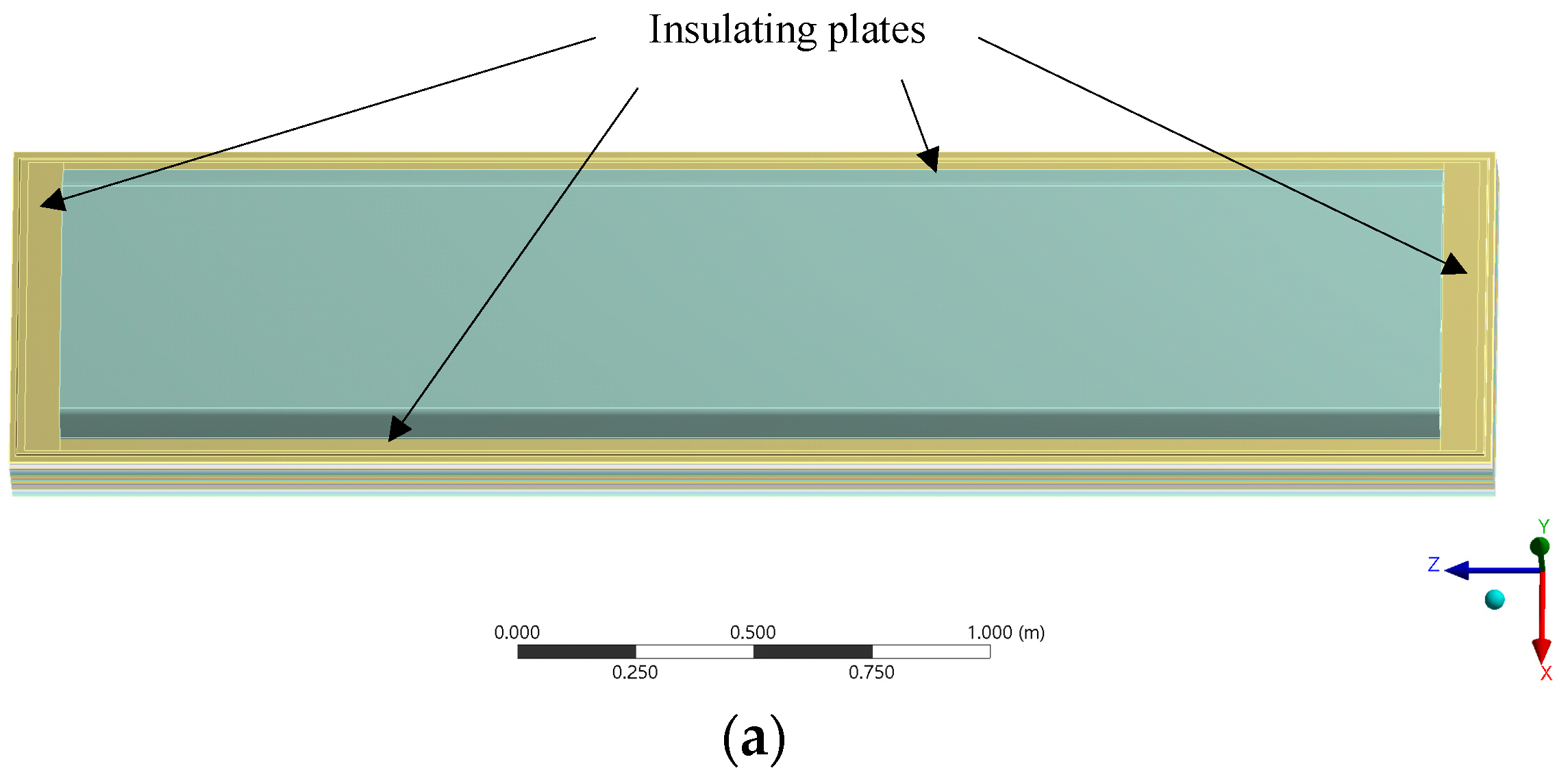
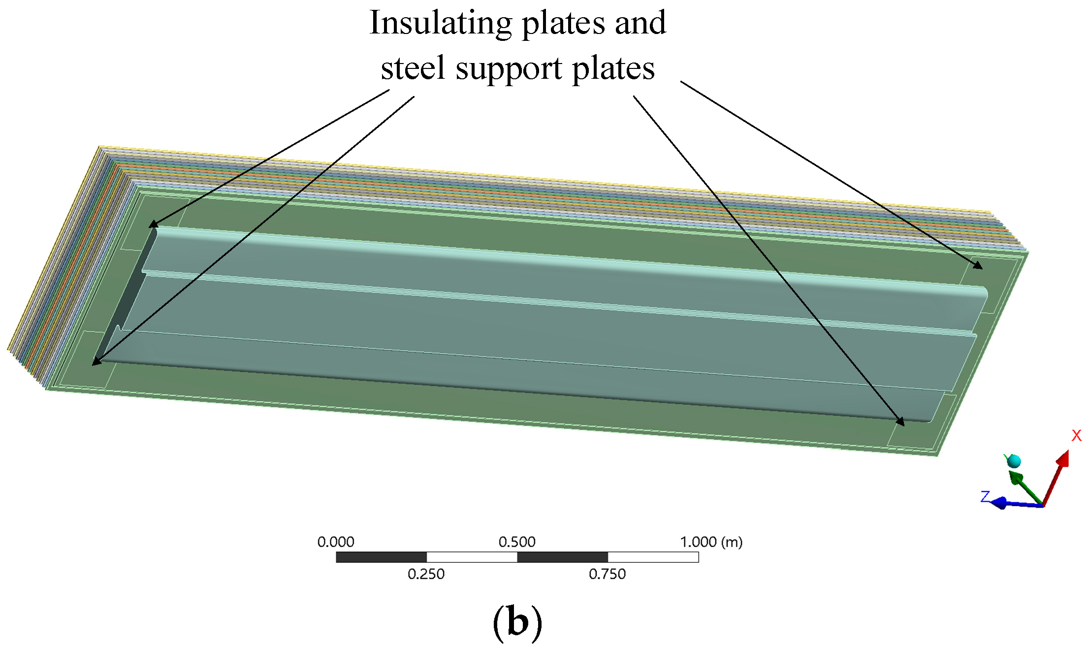
Figure 4.
Temperature field of magnetic pole under normal excitation winding.
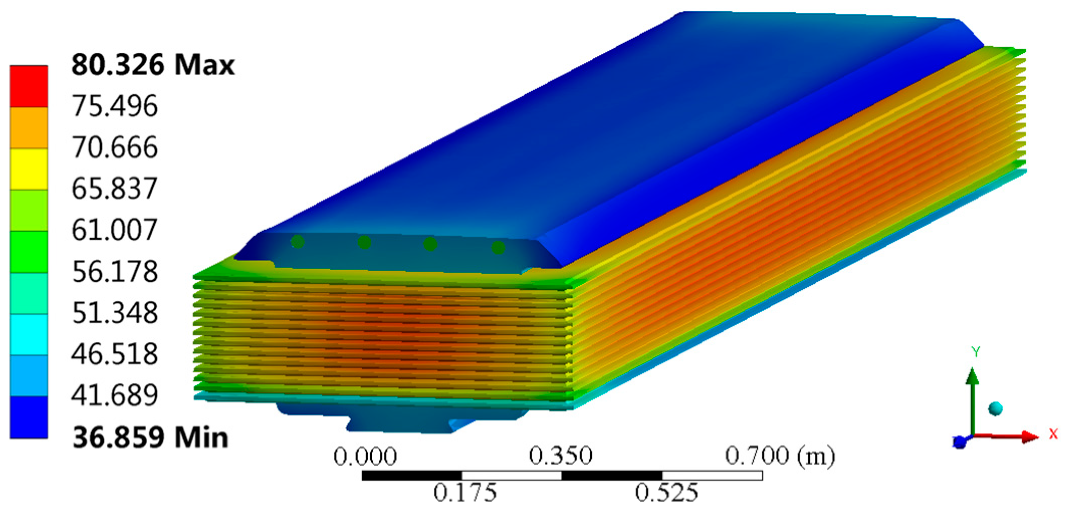
Figure 5.
Distribution of test points.

Figure 6.
Rotor pole temperature field of one-turn short circuit of rotor winding: (a) inter-turn fault of No. 6; and (b) inter-turn fault of No. 12.
Figure 6.
Rotor pole temperature field of one-turn short circuit of rotor winding: (a) inter-turn fault of No. 6; and (b) inter-turn fault of No. 12.

Figure 7.
Temperature of excitation turn in one turn shorted.
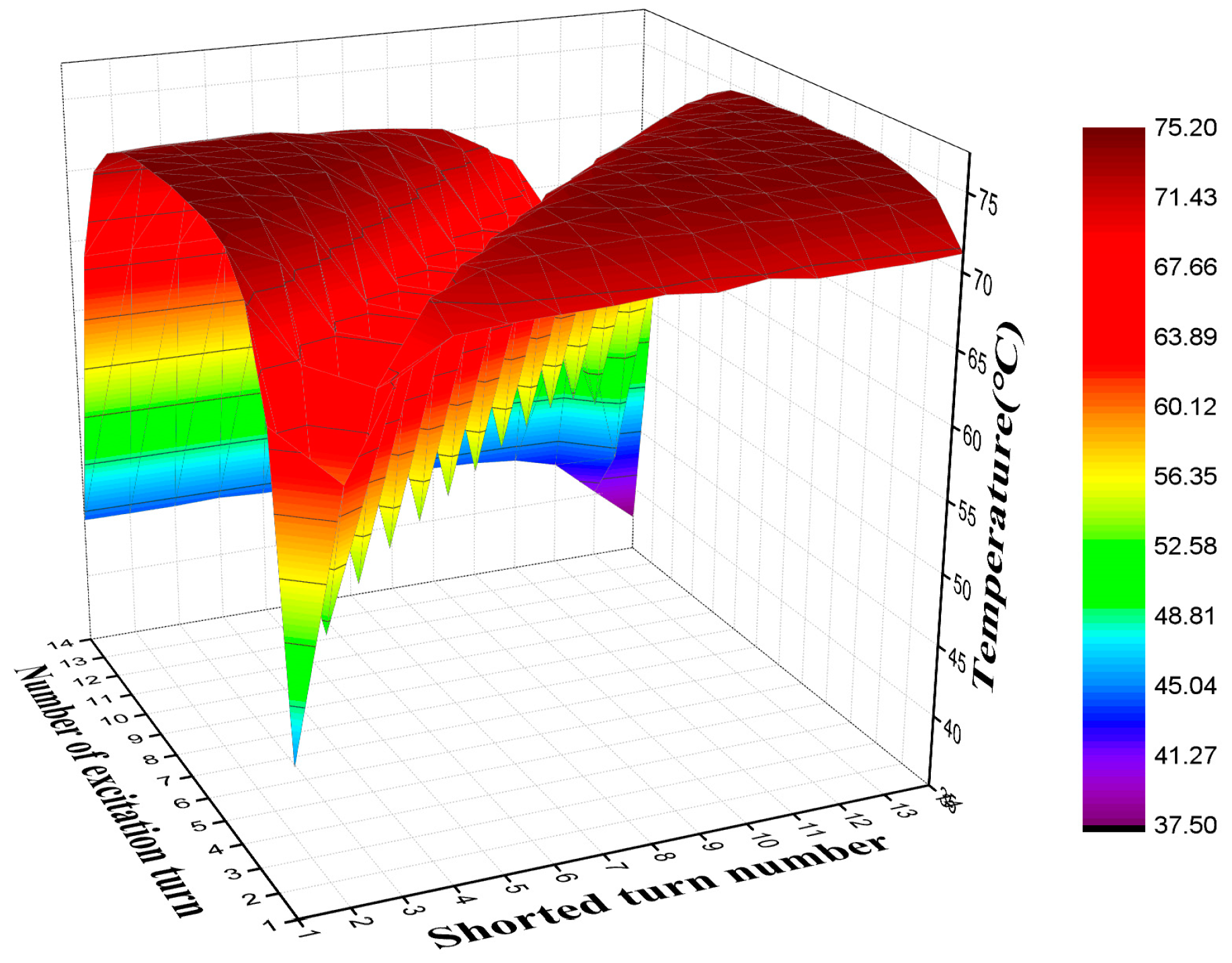
Figure 8.
Multi-turn short circuit temperature change diagram.
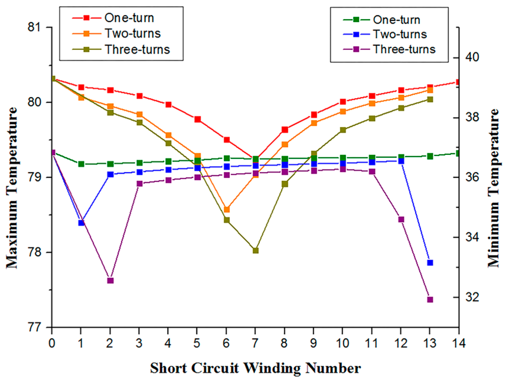
Figure 9.
Rotor magnetic pole temperature field with multiple shorted turns: (a) two-turn short circuit; and (b) three-turn short circuit.
Figure 9.
Rotor magnetic pole temperature field with multiple shorted turns: (a) two-turn short circuit; and (b) three-turn short circuit.
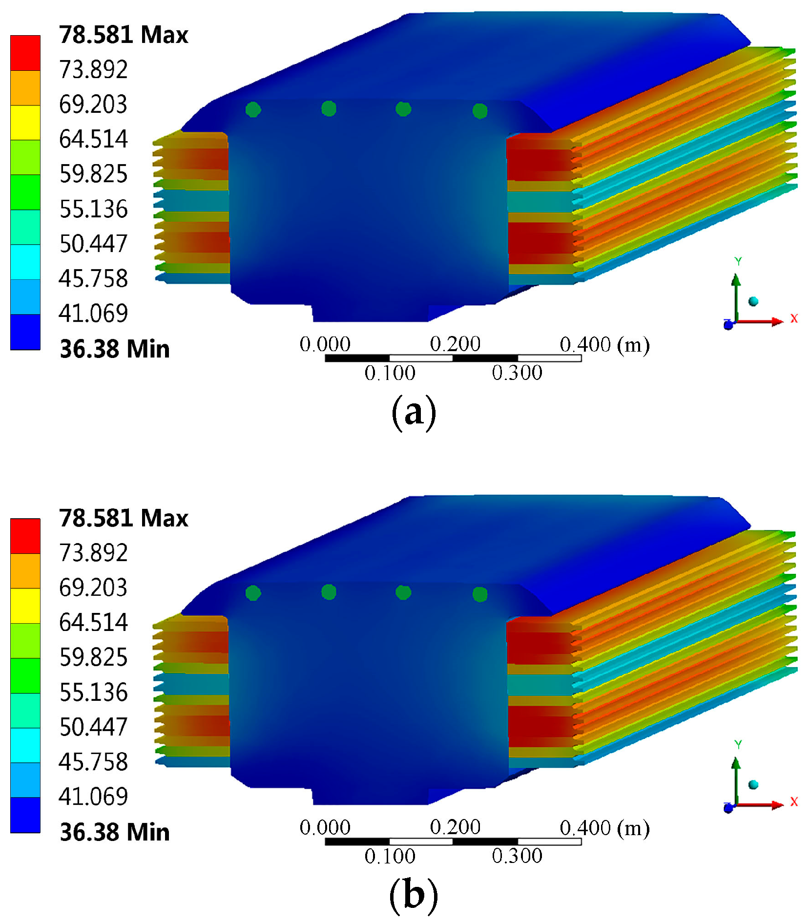
Figure 10.
Thermal deformation of rotor magnetic pole under normal conditions.
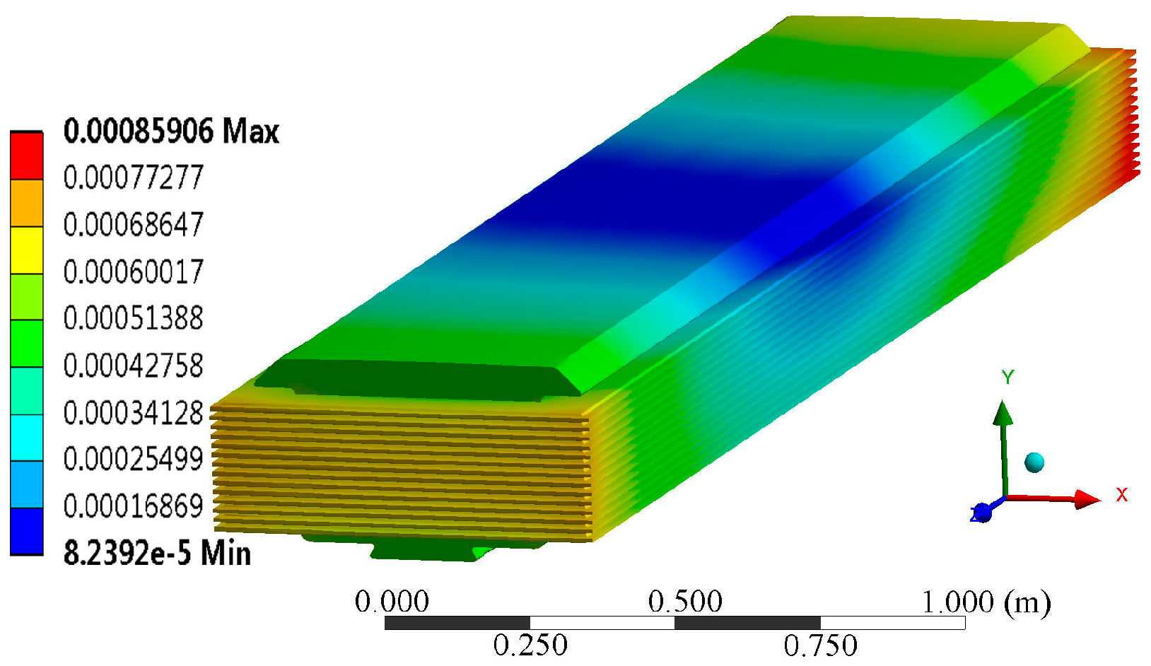
Figure 11.
Thermal deformation of rotor magnetic pole with the sixth to eighth turns shorted.
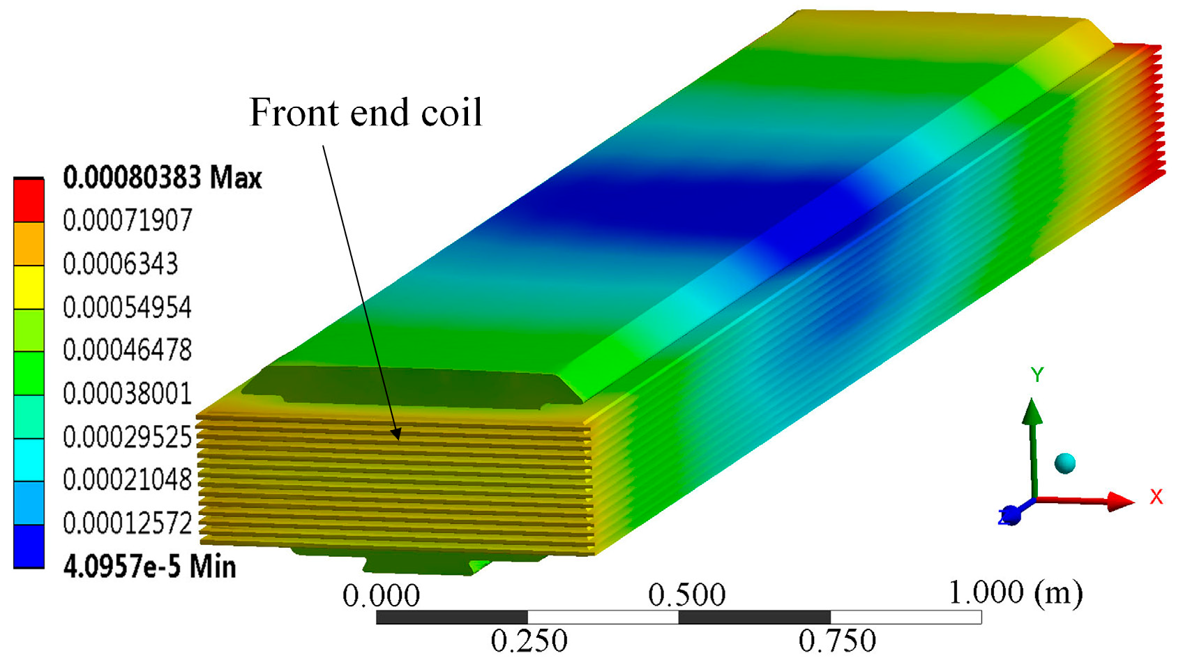
Figure 12.
Thermal deformation of front-end coil of the magnetic pole.
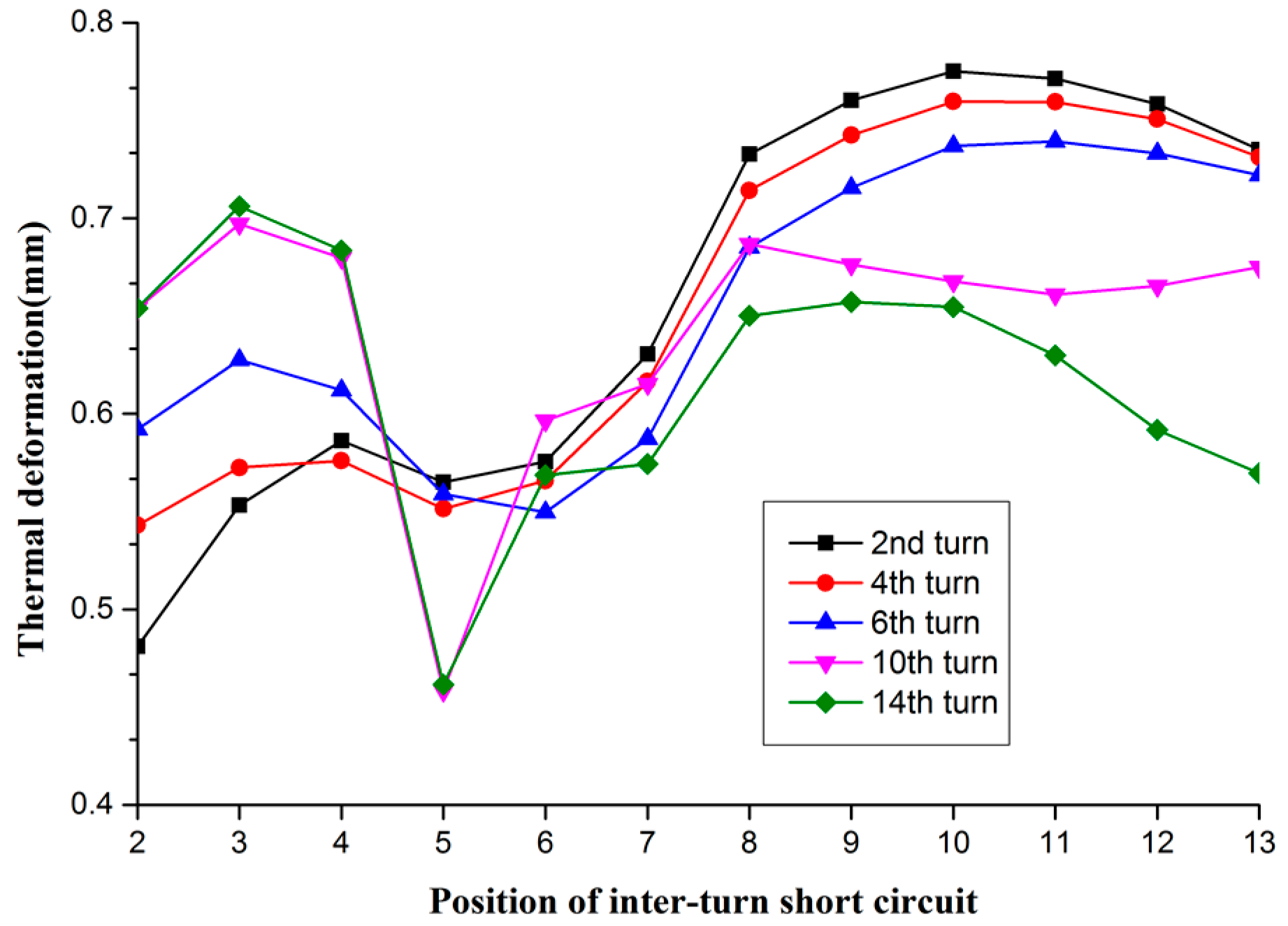
Figure 13.
Thermal stress distribution of magnetic pole under normal conditions.

Figure 14.
Thermal stress distribution of magnetic pole in short circuit: (a) one-turn short circuit; and (b) three-turn short circuit.
Figure 14.
Thermal stress distribution of magnetic pole in short circuit: (a) one-turn short circuit; and (b) three-turn short circuit.

Figure 15.
Effect of different numbers of shorted turns on thermal stress of excitation winding.
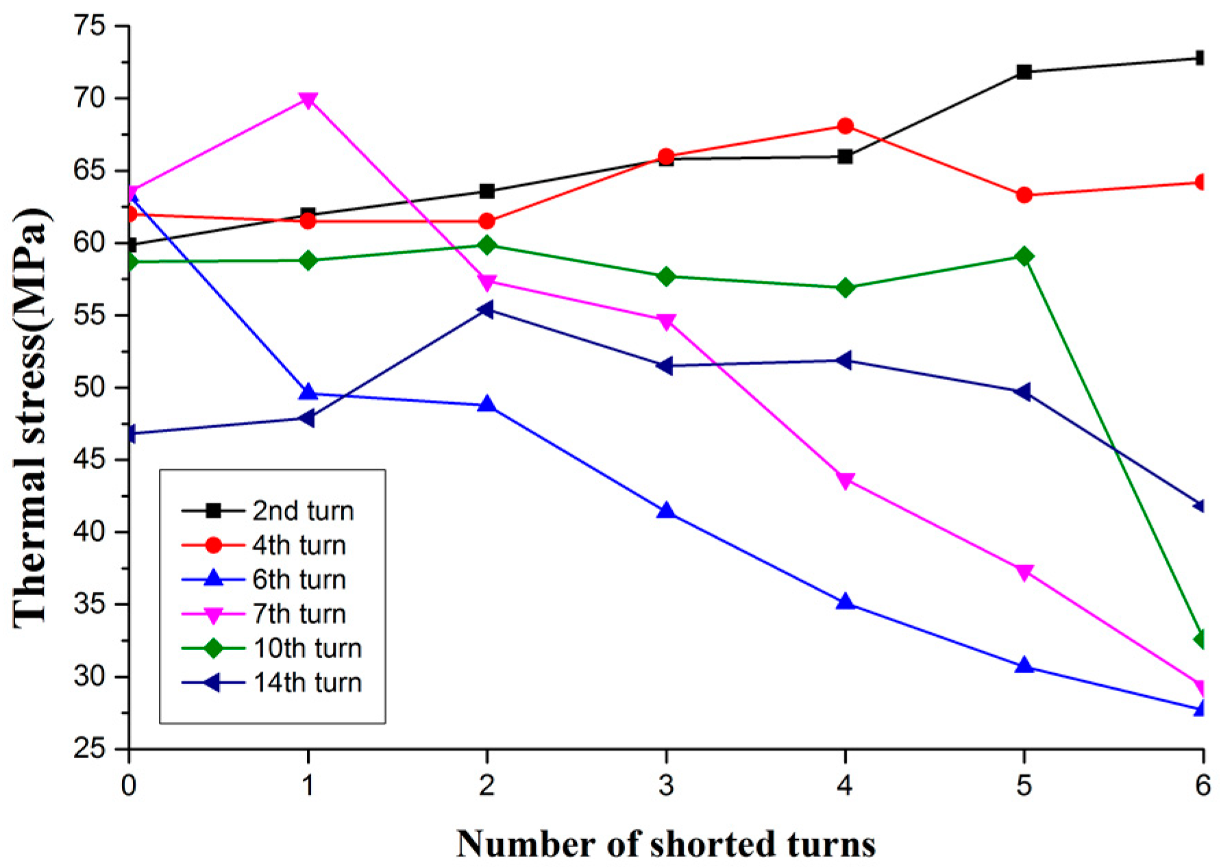
Figure 16.
Thermal stress in the X/Y/Z direction in inter-turn short circuit: (a) 1-x; (b) 3-x; (c) 1-y; (d) 3-y; (e) 1-z; and (f) 3-z.
Figure 16.
Thermal stress in the X/Y/Z direction in inter-turn short circuit: (a) 1-x; (b) 3-x; (c) 1-y; (d) 3-y; (e) 1-z; and (f) 3-z.
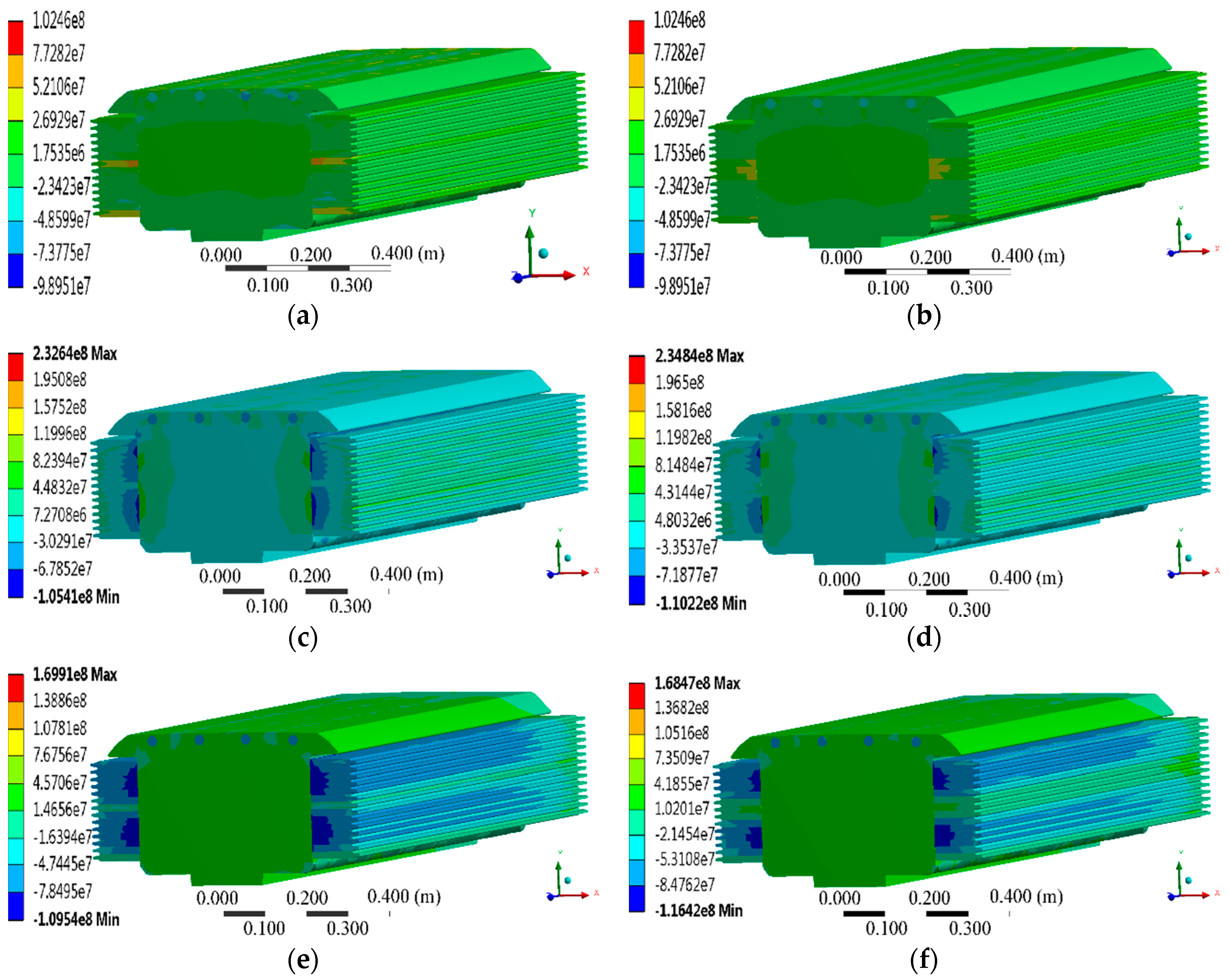
Figure 17.
Thermal stress distribution of magnetic pole at different short circuit locations: (a) 2–4 turn short circuit; (b) 7–9 turn short circuit; and (c) 11–13 turn short circuit.
Figure 17.
Thermal stress distribution of magnetic pole at different short circuit locations: (a) 2–4 turn short circuit; (b) 7–9 turn short circuit; and (c) 11–13 turn short circuit.

Figure 18.
Thermal stress distribution of magnetic pole at different short circuit locations.

Table 1.
Basic parameters of the hydro-generator.
| Model | SF700-80/19760 |
|---|---|
| Rated capacity/MVA | 777.8 |
| Rated power/MW | 700 |
| Rated voltage/kV | 20 |
| Rated current/A | 22,453 |
| Rated rotating speed/rpm | 75 |
| Core length/mm | 2920 |
| Rotor outside diameter/mm | 18,742 |
| Number of winding per pole | 14 |
| Damper winding diameter/mm | 25 |
Table 2.
Comparison of magnetic pole temperature data (Unit °C).
| Number of Test Point | 1 | 2 | 3 | 4 | 5 |
|---|---|---|---|---|---|
| Measured values of literature [26] | 44.3 | 45.3 | 45.7 | 46.5 | 45.4 |
| Calculated values | 43.2 | 44.5 | 44.6 | 44.7 | 43.8 |
Table 3.
Three-turn short circuit thermal stress
| Number of Excitation Turns | Thermal Stress (MPa) | |||
|---|---|---|---|---|
| Upper-Layer | Middle-Layer | Lower-Layer | Normal | |
| 1 | 22.4 | -- | -- | 54.5 |
| 2 | 20.4 | 30.24 | -- | 59.9 |
| 3 | 31.9 | 33 | 32.5 | 60 |
| 4 | 44 | 47.4 | 44.8 | 61.7 |
| 5 | 39 | 49.91 | 48.2 | 61.7 |
| 6 | 41.78 | 46.9 | 46.16 | 63.14 |
| 7 | 41.28 | 53.9 | 52.2 | 63.24 |
| 8 | 46.4 | 47.23 | 50.2 | 63.1 |
| 9 | 44.8 | 48.9 | 48.17 | 62 |
| 10 | 36.46 | 39.93 | 40.18 | 59 |
| 11 | 33 | 35.15 | 31.9 | 56.9 |
| 12 | 29.35 | 29 | 21 | 53.5 |
| 13 | -- | 34 | 20.6 | 46 |
| 14 | -- | -- | 32 | 50.6 |
© 2019 by the authors. Licensee MDPI, Basel, Switzerland. This article is an open access article distributed under the terms and conditions of the Creative Commons Attribution (CC BY) license (http://creativecommons.org/licenses/by/4.0/).
Share and Cite
MDPI and ACS Style
Li, J.; Wang, L. Calculation and Analysis of Rotor Thermal Static Field for Inter-Turn Short Circuit of Large Hydro-Generator Excitation Winding. Energies 2019, 12, 1252. https://doi.org/10.3390/en12071252
AMA Style
Li J, Wang L. Calculation and Analysis of Rotor Thermal Static Field for Inter-Turn Short Circuit of Large Hydro-Generator Excitation Winding. Energies. 2019; 12(7):1252. https://doi.org/10.3390/en12071252
Chicago/Turabian StyleLi, Junqing, and Luo Wang. 2019. "Calculation and Analysis of Rotor Thermal Static Field for Inter-Turn Short Circuit of Large Hydro-Generator Excitation Winding" Energies 12, no. 7: 1252. https://doi.org/10.3390/en12071252
Note that from the first issue of 2016, this journal uses article numbers instead of page numbers. See further details here.