Investigation on Long Term Operation of Thermochemical Heat Storage with MgO-Based Composite Honeycombs
by
Jae Yong Lee
1,*, 
Taesu Yim
1,
Hyouck Ju Kim
1,
Sungkook Hong
1,
Doo Won Seo
2 and
Hong Soo Kim
2 1
Energy Network Laboratory, Korea Institute of Energy Research, Daejeon 34129, Korea
2
Energy Materials Laboratory, Korea Institute of Energy Research, Daejeon 34129, Korea
*
Author to whom correspondence should be addressed.
Energies 2019, 12(7), 1262; https://doi.org/10.3390/en12071262
Submission received: 11 February 2019
/
Accepted: 29 March 2019
/
Published: 2 April 2019
(This article belongs to the Section J: Thermal Management)
Abstract
:The efficient storing and utilizing of industrial waste heat can contribute to the reduction of CO2 and primary energy. Thermochemical heat storage uses a chemical and/or an adsorption-desorption reaction to store heat without heat loss. This study aims to assess the long-term operational feasibility of thermochemical material based composite honeycombs, so that a new thermochemical heat storage and peripheral system were prepared. The evaluation was done by three aspects: The compressive strength of the honeycomb, heat charging, and the discharging capabilities of the thermochemical heat storage. The compressive strength exceeded 1 MPa and is sufficient for safe use. The thermal performance was also assessed in a variety of ways during 100 cycles, 550 h in total. By introducing a new process, the amount of thermochemical-only charging was successfully measured for the first time. Furthermore, the heat charging capabilities were measured at 55.8% after the end of the experiment. Finally, the heat discharging capability was decreased until 60 cycles and there was no further degradation thereafter. This degradation was caused by charging at a too high temperature (550 °C). In comparative tests using a low temperature (450 °C), the performance degradation became slow, which means that it is important to find the optimal charging temperature.
1. Introduction
The efficient utilization of industrial waste heat can contribute to the reduction of CO2 emissions, along with primary energy saving. The industrial waste heat produced by the EU has been estimated to be 304.13 TWh/year out of 3200 TWh/year, 25% of waste heat is in the temperature range of 200 and 500 °C and is released into the atmosphere [1,2]. For the demand side, the building and service sector, in 2012, in the EU, consumed 50% of EU final energy consumption in the form of heating and cooling, and fossil fuel covered 75% of their demand [3]. In order to reduce fossil fuel significantly, it is an efficient way to collect the industrial waste heat and deliver it to other processes, nearby industries or building/service sector. Since the optimization of each process is considerably advanced, it is important to find out the demand of other processes and neighboring sites. Thermal energy networks can provide a linkage from producer to customer, however, establishing a pipeline network requires a lot of investment, and new connections can be made only when a certain amount of demand is always secured. Coordinating the inconsistency between supply and demand is also crucial for lowering the operational cost, so that thermal energy storage is a key component of a thermal energy network and is attracting more interest as a way to provide an appropriate solution to the above mentioned.
Among various heat storage technologies, thermochemical storage is a technique that uses heat to make a chemical reaction and/or an adsorption–desorption reaction between two substances to separate a substance and maintain such a state, so that the energy state does not change until the reaction. In order to use heat, however, it is necessary to select appropriate thermochemical material (TCM) suitable for the temperature range of the waste heat, and also to provide a proper type of reactant to be combined. In addition, it is not possible to carry heat using a pipe since a solid type material is used. Therefore, a method of heat exchanging with TCM can be a stationary reactor or transporting a heat storage medium or a heat storage device itself by using transportation.
Much of the research related to thermochemical heat storage deals with the characterization of TCM materials suitable for the target of the heat charging temperature range. The technique of using thermochemical materials and reactants in a closed space and reacting and separating them repeatedly in a reactor is classified as a chemical heat pump and is not covered in this study. Instead, our focus is on an open system, in which heat is supplied to the TCM container for removing the reactants and for supplying the reactants from the outside when the heat is released.
Studies in terms of TCM deal with different materials, depending on the heat source temperature. In a system with a source temperature of 900–1500 °C, such as the heat storage for Concentrated Solar Power (CSP), attempts to charge and discharge heat in several tens of cycles have been made to assess materials for CoO/Co3O4 [4,5], MnO/Mn3O4 [6] using O2 as a reactant or CaO/CaCO3 [7] using CO2 as a reactant. There was a case study using 90 kg of CoO/Co3O4 [8], and the experiment showed that it was possible to store about 50 kWh through several cycles of operation. A number of studies using CaO/Ca(OH)2 have been conducted for systems with a temperature range of 500–600 °C, and tests were mainly conducted based on a stationary system. In addition to the basic research to observe the one cycle [9] or 20 cyclic stability of materials [10] or 59 cycles [11] in small fixed bed reactor, there has also been research to establish a thermal storage device for cyclic experiments. German Aerospace Center (DLR) constructed a thermal storage system using 2.4 kg [12] and 25 kg [13] of CaO and conducted a study to ascertain the stability of the system along with changes in material and performance through the operation of 35 cycles and more than 10 cycles, respectively. In the temperature range of 350–500 °C, MgO/Mg(OH)2 has been studied [14,15,16,17] as a candidate of heat storage material. Research is mainly on the level of characterization studies using small amounts of TCM, except for some cases that consider a chemical heat pump. In the region below 300 °C, studies on thermochemical thermal storage materials and systems based on adsorption/desorption reactions rather than chemical reactions have been conducted. There are many studies using MgSO4 [18] or zeolite as a typical example. Some studies have been done beyond the evaluation of the material level. In cases where zeolite is used, two mobile storage devices with a capacity of 2.3 MWh and a weight of 14 tons were built. In order to assess the economic feasibility, 87 cycles of heat transport tests were carried out between the waste incinerator and the industrial drying process for one year [19]. Our previous research [20] has focused on understanding the characteristics of TCM and finding the optimal composition for making a TCM honeycomb in order to utilize the waste heat from the steel industry. The target TCM was composed of MgO/Mg(OH)2 for high heat charging density due to the chemical reaction and zeolite 13X for using a fast reaction by adsorption/desorption. In order to improve the characteristics of composite TCM, other studies have been conducted. Criado et al. [21] used Sodium Silicate to improve the mechanical stability of CaO, Mastronardo et al. [22,23] tested Mg(OH)2 with various carbon (Expanded Graphite, Carbon Nanotube, Graphene Oxide) hybrid materials for enhancing the thermal conductivity, which showed a faster output and higher heat charging capability. Shkatulov et al. [24] precipitated Mg(OH)2 into vermiculite pores to make a lower heat charging temperature and larger storage density.
A honeycomb is used as an industrial filter for adsorbing various substances such as Volatile Organic Compound (VOC) due to its convenient disposition, high surface area, and advantage of being advantageous in material exchange. In the case of a heat storage device using sensible heat, beads or pellets were commonly packed in containers rather than a honeycomb. In case of using Phase Change Material (PCM), containers were stored in liquid form or used as an encapsulation type. The purpose of our research is to construct thermochemical composite materials with a honeycomb and make them easy to use in industrial heat storage. Attempts to use honeycombs for heat storage have recently been tried and tested at some institutions. Karagiannakis et al. [25] found that adding Al2O3 in the Co3O4 based honeycomb helped to improve the structural stability from cyclic operations. Li et al. [26] found that adding bentonite to make a zeolite based honeycomb can produce a honeycomb with ease, due to the lubrication, and prevents cracking. In our previous study [20], results showed that a suitable combination of Mg(OH)2/zeolite 13X/bentonite can produce a honeycomb with sufficient strength while maintaining the thermochemical performance. Based on these results, this study aims to carry out the assessment of the long-term operational feasibility of recovering waste heat with thermochemical heat storage using MgO-based composite honeycombs especially for steel industry.
2. Experiments
For evaluating the thermochemical heat storage with a long-term cycling effect, TCM honeycomb samples were prepared and also a new thermochemical heat storage and peripheral system were constructed. TCM was extruded to the honeycomb to serve as the medium of heat storage from an industrial standpoint. The new thermochemical heat storage system was used for evaluating the performance of multiple honeycombs by repeating the heat charging and discharging stages automatically without the operator’s manipulation. During the experiment, temperatures, flow rate, and weight changes were monitored to evaluate the qualitative and quantitative heat storage characteristics of TCM. Thermal performances were assessed in a variety of ways during 100 cycles, 550 h in total. By introducing a new experimental procedure, the amount of thermochemical-only charging was successfully measured for the first time.
2.1. TCM Honeycomb Preparation
Materials and procedures for manufacturing a honeycomb are as follows: Magnesium hydroxide (MagShield S, Martin Marietta Magnesia Specialties, LLC, Baltimore, MD, USA) and 13X type zeolite (Zeolum F-9, Tosoh Corporation, Tokyo, Japan) were mixed into 100:0, 95:5, 90:10, 85:15, and 80:20 by weight ratio. Bentonite (Therm-EX Grout, Wyo-Ben, Inc., Billing, MT, USA) as an inorganic binder and YB-132A (Yuken Industry Co., Ltd., Kariya City, Aichi, Japan) as an organic binder were added to 5 wt% of the pre-mixed PCM raw materials powder, respectively. Tap water was added to the (TCM + binder) mixture before kneading thoroughly. The dough was supplied into the vacuum extruder with 60 cells/in2 mold (Figure 1a) attached. During extrusion (Figure 1b), the honeycomb was cut by 28 cm length and carefully dried in a thermos-hygrostat as shown in Figure 1c.
2.2. System Design
The design concept of the proposed system was to enable a long-term cycling operation and evaluation for the multiple TCM honeycombs. To differentiate this study from our previous setup [20], which was conducted in an enclosed chamber to measure the intrinsic material properties, this study aims to evaluate the thermochemical heat storage properties for a structure nearer to that in a common industrial process. The Piping and Instrument Diagram (P&ID) of the entire system is shown in Figure 2. An air blower (Figure 2 (1)) takes in ambient air, and the flow rate is controlled by a digital inverter up to 0.7 Nm3/h. Temperature and pressure are compensated to adjust the flow rate. The digital flow meter (Figure 2 (2)) measures the flow rate and gives feedback to the control system for maintaining the constant normal flow rate regardless of temperature or pressure change. Two gas inline heaters (Figure 2 (3) and (4)) simulate the waste hot gas supply. They control the gas (air in this experiment) to heat up 600 °C before entering the multi honeycomb reactor. The heating capacities are 6 kW output each, which doubles the heat supply to reduce the heating up time when the honeycomb is charging. Furthermore, by installing the heaters in a tangent direction to the reactor, these form a swirl flow for the heated air to be evenly distributed in the reactor. The reactor (Figure 2 (5)) is the main part of the system. It is equipped with a cartridge with seven honeycombs, and each honeycomb charges the waste heat from hot gas. When it releases heat, it reacts with moisture in the saturated steam introduced from the outside, and it is discharged as superheated steam. A gas cooler (Figure 2 (6)) is the air-to-water heat exchanger to deliver the remaining heat to the city water. A 6 kW output steam generator (Figure 2 (7)) makes saturated steam up to 150 °C, the solenoid on-off valve (Figure 2 (8)) was located in the steam pipeline to control the steam supply to the reactor. The distilled water generator (Figure 2 (9)) converts the city water into distilled water for the steam boiler. The distilled water prevents the scale when the boiler is running for a long time. A drain cooling jacket (Figure 2 (10)) combined with a steam trap (Figure 2 (11)) is added to remove condensed water due to heat loss in the pipeline.
More specifically, a thermochemical heat storage reactor for multiple honeycombs is designed, as shown in Figure 3. The reactor has three inlets, two for hot gas (Figure 3 (1)) and steam (Figure 3 (2)). Hot gas and steam use the same outlet (Figure 3 (3)). As for monitoring the stage of cycles, a K-type 1/8” sheath thermocouple at the inlet of honeycombs (Figure 3 (4)) and seven thermocouples for the purpose of measuring the outlet temperature separately (Figure 3 (5)) are placed on top of each honeycomb. Between the outer cover and inner structure, high-density ceramic wool (Figure 3 (6)) was packed to minimize the heat loss. Because seven casings (Figure 3 (7)) for holding a single TCM honeycomb at a size of 4 cm in diameter and 30 cm in length (Figure 3 (8)) can handle each sample separately. They are assembled in the concept of an exchangeable TCM cartridge (Figure 3 (9)). The TCM cartridge is detachable with the purpose of measuring the weight changes before and after the heat discharging process and also taking some samples for thermogravimetry (TGA) and differential scanning calorimeter (DSC) analysis. Figure 4 shows a layout picture of a multiple TCM honeycombs heat storage system and control setup. Figure 5a is the thermochemical heat storage, Figure 5b is the photograph of the installed reactor, Figure 5c,d present multiple TCM honeycombs located in the cartridge in detail.
2.3. Experimental Procedures
In this study, our system is used to repeat cycles for a long period of heat charging and discharging. The operational procedure is similar to our previous study [20], however, a new operational sequence for heat charging and discharging are applied by considering several changes due to the open system supplied by gas and steam.
- Step 1 (stabilizing the gas flow rate): Before the heat charging, the gas(air) flow rate is adjusted to be constant. While the digital inverter controls the air blower (Figure 2 (1)), the Proportional Integral Derivative (PID) controller finds the optimum duty to maintain the desired flow rate (0.5 Nm/m3). It has a feedback control with a digital flow meter (Figure 2 (2))
- Step 2 (heat charging—dehydration): After the air flow rate becomes constant, gas inline heaters (Figure 2 (3)) start to heat the air to 550 °C. After the ambient temperature of TCM honeycombs reached a turnover temperature, Mg(OH)2 is turned to MgO, which means the heat is charged. The rest of the hot exhaust gas goes into the gas cooler (Figure 2 (6)) to exchange heat with the city water line before exiting the fume hood.
- Step 3 (TCM cooling down): Immediately after the heat charging, the honeycombs are not ready for thermochemical reactions due to their high temperature. It is thus necessary to cool the honeycombs to a lower temperature than the reactants in order to evaluate the ‘no heat loss’ properties after the heat charging and to determine whether the heat charging has been successful. In this step, an air blower supplies ambient air into the cartridge without heating, making the honeycomb temperature lower than the steam temperature (100 °C).
- Step 4 (optional process—measuring the amount of thermochemical heat charging): During the thermochemical heat charging process, the chemical reaction absorbs the additional heat with a sensible heat charging process. Therefore, the gas temperature decreases more than the sensible-only heat charging. Hence, it is expected to have a lower exhaust temperature, however, it is not easy to separately calculate the temperature decrease due to the thermochemical heat charging. Thus, there is an optional step to run the same operation parameter one more time in order to evaluate the amount of heat absorption during the thermochemical process, it is the so-called sensible-only heat charging. After finishing this step, overlapping the temperature behavior of the TCM honeycombs reveals the non-overlapping temperature section due to the different heat charging mechanism. When we calculate the temperature change between Step 3 and Step 2 with the air flow rate, we can calculate how much heat was charged during the thermochemical process. Because of the limited time, however, we conducted this optional step only for validating the thermochemical performances. The analysis of this process will be considered in the next chapter.
- Step 5 (heat discharging—hydration): After cooling down, the solenoid valve (Figure 2 (8)) opens to supply steam to the reactor (Figure 2 (5)). While steam enters the reactor, the steam temperature is maintained at a saturated temperature at ambient pressure due to heat loss (Figure 2 (7)). During the saturation, steam is flown through the cartridge and the reactant is combined with TCM honeycombs, resulting in producing dry, superheated steam. During the experiment, the gas cooler (Figure 2 (6)) cools down the steam before exiting the hood.
- Step 6 (post drying the peripheral devices after heat discharging): During hydration, steam and condensed water can exist somewhere inside the system, including the pipelines. To prevent an electrical shortage when the gas inline heater runs, hot gas (120 °C) is supplied into the system for enough time to dry all the equipment for the next heat charging procedure.
All steps are designed to be controlled automatically by the National Instrument compact DAQ controller and the LabVIEW-based software in Figure 4 (5). When each step is reached, on/off operation according to the state of the device in Table 1 is performed, then it is cycled according to a predetermined time. Figure 6 presents the results of the long-term cyclic experiment with thermochemical heat charging and discharging.
2.4. Set-Up of the Experimental Conditions
Our previous study [20] investigated the optimum compositions of MgO as TCM including several additives. As a result, we finally manufactured a honeycomb using the combination of the materials Mg(OH)2 90 wt% and zeolite 13X 10 wt%. Mg(OH)2 is the main material for heat charging and discharging, zeolite has a role in promoting the chemical reaction of MgO at a low temperature in the early stage of heat discharging.
To investigate the thermochemical performance changes while it is in use, this study conducted a hundred repetitive cyclic experiments under the same conditions. To observe the changes in the thermochemical heat charging density, we obtained sampling and analysis of TCM before beginning the cycle and after ending the 100 cycles experiment. In addition, the changes of the thermochemical heat discharging capabilities in TCM honeycombs were observed every 20 cycles. Measuring the weight difference before and after heat discharging can estimate the heat discharging performance indirectly. In every 20th cycle, the weight of the cartridge was measured after the heat charging, and then it was measured when the heat discharging was finished. Before measuring the heat discharged weight, a dry-out process at 300 °C removed any remaining reactant. Because one mole of MgO reacts with one mole of water molecule, it can represent how much stored heat was used.
3. Results of the Experiments
In this study, we evaluated the TCM honeycombs and thermochemical heat storage during the long-term cycling operation. The evaluation was done by three aspects: The compressive strength of the honeycomb, heat charging, and the discharging capabilities of storage. In order to assume the actual usage in the industry, hot gas was used in the role of waste heat in the heat charging, and also steam was used as the reactant supply to remove excessive moisture and produce dry steam in the heat discharging. A TCM cartridge in the heat storage system used seven honeycombs to ensure a sufficient heat capacity and to investigate differences in location. Temperature changes in heat charging/discharging capabilities were investigated in various ways while the heat storage performed 100 cyclic operations.
3.1. Investigating Compressive Strength of Composite Honeycombs
The dried honeycomb should be heated to 500 °C to remove organic binder before applying the material for heat storage use, which is defined as debinding. The debinding temperature is much lower than the sintering temperature, as a preventive measure to avoid exposure to high temperature. When Mg(OH)2 stays at a high temperature, it is converted to medium-burn or hard-burn MgO and loses reversibility. Since the strength of the debinded honeycomb can be lowered due to the debinding temperature, it was necessary to check whether the strength of the honeycomb was sufficient for handling. Samples for measuring the compressive strength were taken before and after debinding, respectively. The compressive test specimens were cylindrical honeycomb shaped, the diameter of which were 36 mm and the length of which were 40 mm. The compressive test was conducted in accordance with ASTM D 695-15 and crosshead speed was 1 mm/min. Six samples were tested for all combinations before and after the experiment and the mean value was taken. Figure 7 shows the compressive strength of the 0–20 wt% zeolite addition in honeycombs before and after debinding. The compressive strengths of the dried honeycomb before heat treatment were above 6 MPa and were increased as the amount of added zeolite was increased. On the other hand, the compressive strengths of the debinded honeycomb became lower than that of dried ones due to decomposition of the organic binder. However, the compressive strength after debinding was also above 1 MPa due to indecomposable inorganic binder remaining. Thus, the prepared honeycombs, through the addition of an inorganic and organic binder, can be sufficient for safe use without concern of their becoming broken or cracked.
3.2. Investigating the Thermochemical Heat Charging Behaviors
During thermochemical heat charging process, both thermochemical and sensible heat charging take place at the same time. Therefore, it is not easy to evaluate the sole effect of thermochemical phenomenon. In general, thermochemical heat storage has the advantage of long-term heat storage and utilization, it is important to know how much and how long to charge is necessary for industrial applications. Therefore, we attempted new method to compare the difference between two heat charging temperature profiles under the same conditions, one is thermochemical and sensible heat charging the other is sensible-only heat charging. During a cycle of heat charging process, we added the additional intermediate process to repeat heat charging step. This step is described in Step 4 at Table 2. Figure 8a,b each show the results of a series of experiment.
Figure 8a shows the conventional step for the heat charging process. Hot gas of 300 °C passed through the honeycombs for a sufficient time to completely remove adsorbed and excess water. Next, a heat charging process supplied 550 °C until the outlet temperatures of the honeycombs became stable. After the corresponding step, as shown in Figure 8b, an additional step was continued to cool the system down again to 300 °C for matching with the previous initial condition, and then supplied 550 °C with the same flow rate until the honeycomb outlet temperature became stable. After that, the overlapping both temperature profiles of Figure 8a,b disclosed the temperature differences between the thermochemical with sensible and sensible-only heat charging. Because the thermochemical heat charging absorbed additional heat, the honeycomb outlet temperature of conjugated heat charging should be lower than that of sensible-only. As a result, Figure 9a–f show the separate analysis of each honeycomb regarding the time-series behavior of instantaneous heat charging only by the thermochemical reaction. As already known, thermochemical heat charging of Mg(OH)2 began when the gas temperature of the honeycomb inlet was over 400 °C. Since the hot gas flow rate was controlled as a constant and it is assumed that the flow was uniformly distributed, using temperature differences and flow rates can separate the instantaneous thermochemical heat charging. Furthermore, the appropriate heat charging period can be estimated, thermochemical heat charging profile have shown that approximately 3000 s was a sufficient time to charge. This result shows that a thermochemical heat storage user can decide the optimum exposure time of heat charging or exchanging the next honeycombs if the user considered to use a TCM honeycomb not discharging immediately but discharging after several days or a seasonal interval.
As seen in Figure 9, integrating the instantaneous heat charging made the calculation of the total amount of thermochemical heat charged. Table 2 is the instantaneous and accumulated heat charging only by thermochemical reaction in each honeycomb. The TCM cartridge could charge 115.8 W per honeycomb at the peak, accumulate 46.9 Wh per honeycomb during a heat charging process. In the viewpoint of the entire thermochemical heat storage, the peak instantaneous heat charging of the entire honeycomb was 810.4 W, and the final amount of heat charging was calculated as 328.6 Wh.
In the experiment, temperature measurement is only possible at the inlet and outlet of honeycombs, so it is limited to observe the internal behavior of the thermochemical reactor. To better understand the heat charging process, we performed additional numerical modeling and simulation to analyze the heat and mass transfer inside the cartridge. Geometry modeling and simulation is done by the Solidworks and Solidworks flow simulator (by Dassault Systems), the actual dimension and experimental data were used to set all the numerical boundary conditions. As a result, Figure 10a,b show the temperature and velocity profiles in the longitudinal direction of each honeycomb, Figure 11a,b present a section cut horizontally and vertically to show how the temperature and velocity was distributed. The simulation result shows that hot gas entering the tangential direction through two inlets were evenly distributed to go into honeycombs by the swirl effect. Inlet temperatures of each honeycomb were uniform, even though inlet velocities had some difference depending on the locations. The center honeycomb (Honeycomb-7), however, had a lower inlet temperature and velocity than the others, due to flow circulation. This implies that the thermochemical heat charging of the center honeycomb could have a longer charging time than others. This result matches well with our experimental data, as shown at Figure 9h, the heat charging to Honeycomb-7 was delayed compared with others. Comparison with the experimental and numerical results show that the improvement of inlet uniformity can make the performance of the thermochemical heat charging better, and reduce the heat charging and discharging deviations.
3.3. Effect of Long-Term Cyclic Operation: Heat Charging Capability
We analyzed the heat charging capability change during 100 cycles of hydration and dehydration. Before the cyclic test, a small amount of TCM material was taken out from each of the seven honeycombs and then they were fully-hydrated with water before conducting DSC analysis for determining the heat charging density. After completing the cycles, the same sampling and analyzing procedure were conducted. The results are shown in Table 3. Before the charging–discharging cycle, the average heat charging density was 2.02 GJ/m3. After 100 cycles, the average heat charging density dropped to 1.13 GJ/m3, which is 55.8% of the original values.
Figure 12a,b is the DSC results as heat flow and heat storage density at the beginning of cycle, respectively. After the cycle, compared with the Figure 12c,d, heat charging capabilities were evenly reduced and did not show any particular tendency for each honeycomb location. The reason we can estimate is that as the MgO particles agglomerated larger due to repetitive heat charging, the reactant could not diffuse inside the particle. Otherwise, some of light-burn MgO could have been changed to a medium-burn MgO due to the high heat storage temperature. Higher heat charging temperatures can affect the irreversible energy due to change in crystal structure.
3.4. Effect of Long-Term Cyclic Operation: Heat Discharging Capability
As an industrial aspect of heat storage application, how much honeycomb TCM can release heat is also an important consideration. In the case of using TCM as powder, the size of the initial small TCM fine particles will agglomerate while the storage material is repeating the heat charging and discharging. Therefore, the diffusion of the reactant molecule is more difficult, and the heat discharging capabilities become worse. Honeycomb as TCM, on the other hand, has a number of paths so that it can deliver reactants not only by diffusion but also by convection, allowing a faster mass transfer to the TCM and heat release. In this study, our experimental setup could observe the heat discharging capabilities of a honeycomb TCM during cyclic operation. The cartridge for holding honeycombs can be taken out after conducting the heat charging and discharging cycle. We measured the weight of the honeycombs to calculate the amount of discharging. Since one MgO molecule reacts with one H2O molecule and releases heat, it is possible to estimate the total amount of the chemical reaction by calculating the weight difference before and after the response as a mole. For this calculation, the weight of the cartridge was measured after heat charging every 20 cycles, and then measured again after heat discharging process. Before measuring the weight after the chemical reaction, we performed the additional process of supplying hot gas of 300 °C for removing the excess water.
Figure 13a shows the trend of the heat discharging rate with the heat charging temperature and repetitive cycle. For evaluating the heat discharging capability, we measured the weight of the cartridge after heat charging every 20 cycles, and then measured again after the heat discharging process. The heat discharging rate indicates how much the reaction occurred when heat is discharged after the heat charging is done, and the higher the heat discharging rate, the more the reaction occurred. When the heat charging temperature was 550 °C, the heat discharging capability became 50.8% as the initial 20 cycles progressed. After 60 cycles, the heat discharging capability was stabilized between 32.1–33.6%, and no further degradation was observed. In contrast, when the heat charging temperature was 450 °C, the heat discharging capability was reduced to 78.5% in the initial 20 cycles and also stable at 58.7–62.2% after 60 cycles. Figure 13b shows the highest temperature rise in each cycle during the heat discharging process. As the cycle progressed, the temperature rise during the heat discharging continued to decrease with a negative correlation. Figure 14a,b compares the XRD patterns of TCM (Honeycomb-1) after one cycle and 100 cycles after discharging. The honeycomb sample after one cycle had distinct zeolite peaks but MgO and Mg(OH)2 peaks were not so obvious. However, the sample after 100 cycles showed significant MgO and Mg(OH)2 peaks compared with that of zeolite. Those results can explain the formation process of MgO and Mg(OH)2. After 100 cycles, the highest peak of Mg(OH)2 was unexpected, considering the fully hydrated state. The plausible explanation of this phenomenon is the MgO crystal grows as the hydration-dehydration cycle accumulates. If MgO became a big crystal, a longer diffusion path for the reactant adversely affected the reaction, as a result, only a small amount of magnesium hydroxide took part in the dehydration–hydration reaction. The relatively low zeolite peaks in Figure 14b after 100 cycles is also another explanation for low heat discharging capabilities.
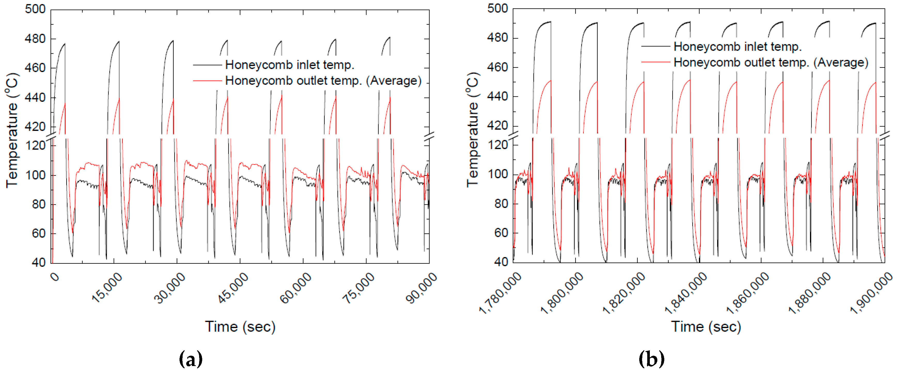
The most likely reason for the low peak is that zeolite was decomposed or transformed into an irreversible material by reacting with other materials when the honeycombs were exposed to high temperatures near 500 °C during the heat charging process, as seen in Figure 15a,b. These results show that the role of the zeolite added to promote the chemical reaction is reduced. Going back to Figure 13a, there is a comparative experiment that the hot gas temperature is 450 °C. This result maintained a higher heat discharging rate and was less degraded than that of 550 °C, it may provide a clue that shows that exposure to the hot gas temperature can be a key factor for deciding the degradation of thermochemical materials.
4. Discussions
Quantitative and qualitative experiments and analyzes of thermal charging and discharging have helped to understand the properties of thermochemical materials for the thermal storage. During a long term heat storage, the thermal charging and discharging capabilities of the TCM composite honeycomb, reduced until about 60 cycles had elapsed, was investigated. During the heat charging, the temperature was the most significant factor that affected the degradation. When the honeycomb inlet temperature exceeded 500 °C, the high temperature can affect the change in the crystal structure and increase the irreversibility of the crystal. Moreover, a repetitive cycle could cause the MgO crystal growth, impeding the diffusion of reactant into the TCM. The high heat charging temperature was also found to affect the ability to discharge heat. As can be seen from the XRD results, the zeolite decomposed or reacted with other substances to promote the conversion to irreversible materials. Experimental results showed that the overall reaction rate was lowered by reducing the role of zeolites in promoting chemical reactions at the beginning of the heat discharging. This analysis can be done through comparative experiments performed with different thermal charging temperatures. When the hot gas temperature was 450 °C, TCM maintained a higher heat discharging rate and was less degraded than that of 550 °C, as shown in Figure 13a, it is possible that setting the hot gas temperature appropriately according to the physical properties of the TCM composite material can be a key factor for preventing the degradation of the thermochemical material during long term use.
5. Conclusions
In our study, we considered making the thermochemical material (TCM) into a honeycomb shape, a form commonly seen in the industry. We also designed and manufactured thermochemical thermal storage systems with detachable cartridges for use with the honeycomb. This system aims to store the waste heat in the form of gas, and then to dissipate heat to produce superheated steam, which is commonly used in general production lines. Based on our result of a previous study [20], a honeycomb was successfully extruded using the composition of Mg(OH)2 and zeolite 13X. In order to assess the applicability of the honeycomb, a compressive strength test was carried out before and after debinding. There were trends that showed that the more zeolite contents, the higher compressive strength. The debinded honeycomb with the composition we selected (Mg(OH)2 90 wt%, zeolite 13X 10 wt% and bentonite 5 wt% were added to the mixed TCM powders) could maintain above 1 MPa, it has sufficient strength to handle and carry.
Our thermochemical heat storage system ran 100 consecutive cycles to observe the performance variation through repeated heat charging and discharging of seven honeycombs in a cartridge. During 100 cycles, the long-term changes of heat charging and discharging capabilities were assessed in a various way. From the aspect of heat charging capability, we developed and verified a new method of measuring the amount of heat charging only by thermochemical, and conducted an experiment to observe the change of heat storage performance before and after cycling through DSC analysis.
In order to analyze the heat charging capability by the thermochemical reaction, conducting the same consecutive heat charging process could decouple the amount of sensible and thermochemical heat charging. From the result, we could obtain the instantaneous and accumulated heat only by thermochemical heat charging. TCM cartridge with seven honeycombs could charge 810.4 W at the peak moment, accumulate 328.6 Wh during a heat charging process.
In addition, differential scanning calorimetry (DSC) had been used at the beginning and the end of the entire experiment to evaluate the changes in heat charging capabilities. Before charging-discharging cycle, the average heat charging density was 2.02 GJ/m3. After 100 cycles, the average heat charging density dropped to 1.13 GJ/m3, which is 55.8% of the original values.
For evaluating the heat discharging capability, we measured the weight of the cartridge after heat charging every 20 cycles, and then measured again after heat discharging process. When the heat charging temperature was 550 °C, the heat discharging capability became 50.8% as the initial 20 cycles progressed. After 60 cycles, the heat discharging capability was stabilized between 32.1–33.6%, and no further degradation was observed. In contrast, when the heat charging temperature was 450 °C, the heat discharging capability was reduced to 78.5% in the initial 20 cycles and also stable at 58.7–62.2% after 60 cycles.
Author Contributions
Conceptualization, J.Y.L., H.J.K. and H.S.K.; Methodology, H.S.K., J.Y.L. and T.Y.; System design, H.J.K., J.Y.L and T.Y.; Numerical modeling and analysis, S.H. and J.Y.L; Validation, J.Y.L, T.Y. and H.S.K.; Investigation, T.Y.; Writing—Original Draft Preparation, J.Y.L.; Writing—Review & Editing, J.Y.L. and H.S.K.; Experiment, T.Y., J.Y.L and D.W.S.; Supervision, J.Y.L. and H.S.K.; Project Administration, H.S.K.; Funding Acquisition, H.S.K.
Funding
This work was supported by the Energy Efficiency & Resources Program of the Korea Institute of Energy Technology Evaluation and Planning (KETEP), granted financial resource from the Ministry of Trade, Industry & Energy, Republic of Korea. (No. 20152020104810).
Conflicts of Interest
The authors declare no conflict of interest.
References
- Papapetrou, M.; Kosmadakisb, G.; Cipollinaa, A.; Commarea, U.; Micale, G. Industrial waste heat: Estimation of the technically available resource in the EU per industrial sector, temperature level and country. Appl. Therm. Eng. 2018, 138, 207–216. [Google Scholar] [CrossRef]
- Fleiter, T.; Steinbah, J.; Ragwitz, M. Mapping and Analyses of the Current and Future (2020–2030) Heating/Cooling Fuel Deployment (Fossil/Renewables). Available online: https://ec.europa.eu/energy/sites/ener/files/documents/Report%20WP1.pdf (accessed on 10 February 2019).
- Communication from the Commission to the European Parliament, the Council, the European Economic and Social Committee and the Committee of the Regions: An EU Strategy on Heating and Cooling 2016. Available online: https://ec.europa.eu/energy/sites/ener/files/documents/1_EN_ACT_part1_v14.pdf (accessed on 10 February 2019).
- Agrafiotis, C.; Roeb, M.; Schmücker, M.; Sattler, C. Exploitation of thermochemical cycles based on solid oxide redox systems for thermochemical storage of solar heat. Part 1: Testing of cobalt oxide-based powders. Sol. Energy 2014, 102, 189–211. [Google Scholar] [CrossRef]
- Singh, A.; Tescari, S.; Lantin, G.; Agrafiotis, C.; Roeb, M.; Sattler, C. Solar thermochemical heat storage via the Co3O4/CoO looping cycle: Storage reactor modelling and experimental validation. Sol. Energy 2017, 144, 453–465. [Google Scholar] [CrossRef]
- Randhir, K.; King, K.; Rhodes, N.; Li, L.; Hahn, D.; Mei, R.; AuYeung, N.; Klausnera, J. Magnesium-manganese oxides for high temperature thermochemical energy storage. J. Energy Storage 2019, 21, 559–610. [Google Scholar] [CrossRef]
- Benitez-Guerrero, M.; Valverde, J.; Sanchez-Jimenez, P.; Sanchez-Jimenez, P.; Perejon, A.; Perez-Maqueda, L. Multicycle activity of natural CaCO3 minerals for thermochemical energy storage in concentrated solar power plants. Sol. Energy 2017, 153, 188–199. [Google Scholar] [CrossRef]
- Tescari, S.; Singh, A.; Oliveira, L.; Breuer, S.; Agrafiotis, C.; Roeb, M.; Sattler, C.; Marcher, J.; Pagkoura, C.; Karagiannakis, G.; et al. Experimental proof of concept of a pilot-scale thermochemical storage unit. AIP Conf. Proc. 2017, 1850, 090006. [Google Scholar]
- Yan, J.; Zhao, C. Experimental study of CaO/Ca(OH)2 in a fixed-bed reactor for thermochemical heat storage. Appl. Energy 2016, 175, 277–284. [Google Scholar] [CrossRef]
- Dai, L.; Long, X.; Lou, B.; Wu, J. Thermal cycling stability of thermochemical energy storage system Ca(OH)2/CaO. Appl. Therm. Eng. 2018, 133, 261–268. [Google Scholar] [CrossRef]
- Kuwata, K.; Esaki, T.; Iwase, D.; Ito, H.; Li, S.; Yang, X.; Huang, H.; Kobayashi, N. Long-Term Durability and Reactivation of Thermochemical Heat Storage Driven by the CaO/Ca(OH)2 Reversible Reaction. J. Mater. Sci. Chem. Eng. 2017, 5, 23–32. [Google Scholar]
- Schmidt, M.; Linder, M. Power generation based on the Ca(OH)2/ CaO thermochemical storage system—Experimental investigation of discharge operation modes in lab scale and corresponding conceptual process design. Appl. Energy 2017, 203, 594–607. [Google Scholar] [CrossRef]
- Schmidt, M.; Szczukowski, C.; Roßkopf, C.; Linder, M.; Wörner, A. Experimental results of a 10 kW high temperature thermochemical storage reactor based on calcium hydroxide. Appl. Therm. Eng. 2014, 62, 553–559. [Google Scholar] [CrossRef] [Green Version]
- Kato, Y.; Nakahata, J.; Yoshizawa, Y. Durability characteristics of the hydration of magnesium oxide under repetitive reaction. J. Mater. Sci. 1999, 34, 475–480. [Google Scholar] [CrossRef]
- Thomas, J.J.; Musso, S.; Prestini, I. Kinetics and Activation Energy of Magnesium Oxide Hydration. J. Am. Ceram. Soc. 2014, 97, 275–282. [Google Scholar] [CrossRef]
- Shand, M. Calcination of Magnesia Hydroxide and Carbonate. In The Chemistry and Technologies of Magnesia; Shand, M.A., Ed.; John Wiley & Sons: Hoboken, NJ, USA, 2006; pp. 83–96. [Google Scholar]
- Gravogl, G.; Knoll, C.; Welch, J.; Artner, W.; Freiberger, N.; Nilica, R.; Eitenberger, E.; Friedbacher, G.; Harasek, M.; Werner, A.; et al. Cycle Stability and Hydration Behavior of Magnesium Oxide and Its Dependence on the Precursor-Related Particle Morphology. Nanomaterials 2018, 8, 795. [Google Scholar] [CrossRef]
- Van Essen, V.M.; Zondag, H.A.; Cot Gores, J.; Bleijendaal, L.P.J.; Bakker, M.; Schuitema, R.; van Helden, W.; He, Z.; Rindt, C. Characterization of MgSO4 Hydrate for Thermochemical Seasonal Heat Storage. J. Sol. Energy Eng. 2009, 131. [Google Scholar] [CrossRef]
- Krönauera, A.; Lävemanna, E.; Brücknera, S.; Hauera, A. Mobile Sorption Heat Storage in Industrial Waste Heat Recovery. Energy Procedia 2015, 73, 272–280. [Google Scholar] [CrossRef] [Green Version]
- Yim, T.; Kim, H.; Lee, J. Cyclic Assessment of Magnesium Oxide with Additives as a Thermochemical Material to Improve the Mechanical Strength and Chemical Reaction. Energies 2018, 11, 2366. [Google Scholar] [CrossRef]
- Criado, Y.; Alonso, M.; Abanades, J. Enhancement of a CaO/Ca(OH)2 based material for thermochemical energy storage. Sol. Energy 2016, 135, 800–809. [Google Scholar] [CrossRef]
- Mastronardo, E.; Bonaccorsi, L.; Kato, Y.; Piperopoulos, E.; Lanza, M.; Milone, C. Thermochemical performance of carbon nanotubes based hybrid materials for MgO/H2O/Mg(OH)2 chemical heat pumps. Appl. Energy 2016, 181, 232–243. [Google Scholar] [CrossRef]
- Mastronardo, E.; Kato, Y.; Bonaccorsi, L.; Piperopoulos, E.; Milone, C. Thermochemical Storage of Middle Temperature Wasted Heat by Functionalized C/Mg(OH)2 Hybrid Materials. Energies 2017, 10, 70. [Google Scholar] [CrossRef]
- Shkatulov, A.; Ryu, J.; Kato, Y.; Aristov, Y. Composite material Mg(OH)2/vermiculite: A promising new candidate for storage of middle temperature heat. Energy 2012, 44, 1028–1034. [Google Scholar] [CrossRef]
- Karagiannakis, G.; Pagkoura, C.; Halevasa, E.; Baltzopoulou, P.; Konstandopoulos, A. Cobalt/cobaltous oxide based honeycombs for thermochemical heat storage in future concentrated solar power installations: Multi-cyclic assessment and semi-quantitative heat effects estimations. Sol. Energy 2016, 133, 394–407. [Google Scholar] [CrossRef]
- Li, Y.; Perera, S.; Crittenden, B.; Bridgwater, J. The effect of the binder on the manufacture of a 5A zeolite monolith. Powder Technol. 2001, 116, 85–96. [Google Scholar] [CrossRef]
Figure 1.
Manufacturing a honeycomb with thermochemical material (TCM): (a) Extrusion mold with 60 cells/in2, (b) on-going vacuum extrusion of the honeycomb and (c) extruded and dried honeycombs.
Figure 1.
Manufacturing a honeycomb with thermochemical material (TCM): (a) Extrusion mold with 60 cells/in2, (b) on-going vacuum extrusion of the honeycomb and (c) extruded and dried honeycombs.

Figure 2.
Piping and Instrument Diagram (P&ID) for TCM heat storage: (1) Air blower, (2) digital flow meter, (3) gas inline heater #1, (4) gas inline heater #2, (5) thermochemical heat storage reactor, (6) gas cooler, (7) steam generator, (8) solenoid on-off valve, (9) distilled water generator, (10) drain cooling jacket and (11) steam trap.

Figure 3.
3D schematics of thermochemical heat storage reactor: (1) Hot gas inlet, (2) steam inlet, (3) hot gas/steam outlet, (4) temperature sensor for inlet gas/steam and steam condensate drain, (5) temperature sensors for each honeycomb outlet, (6) thermal insulation layer, (7) honeycomb casing, (8) TCM honeycomb and (9) cartridge for multiple honeycombs.

Figure 4.
Photograph of the thermochemical heat storage system: (1) Air blower, (2) gas inline heaters for heat charging, (3) thermochemical heat storage reactor, (4) steam generator and (5) control and monitoring panel.
Figure 4.
Photograph of the thermochemical heat storage system: (1) Air blower, (2) gas inline heaters for heat charging, (3) thermochemical heat storage reactor, (4) steam generator and (5) control and monitoring panel.
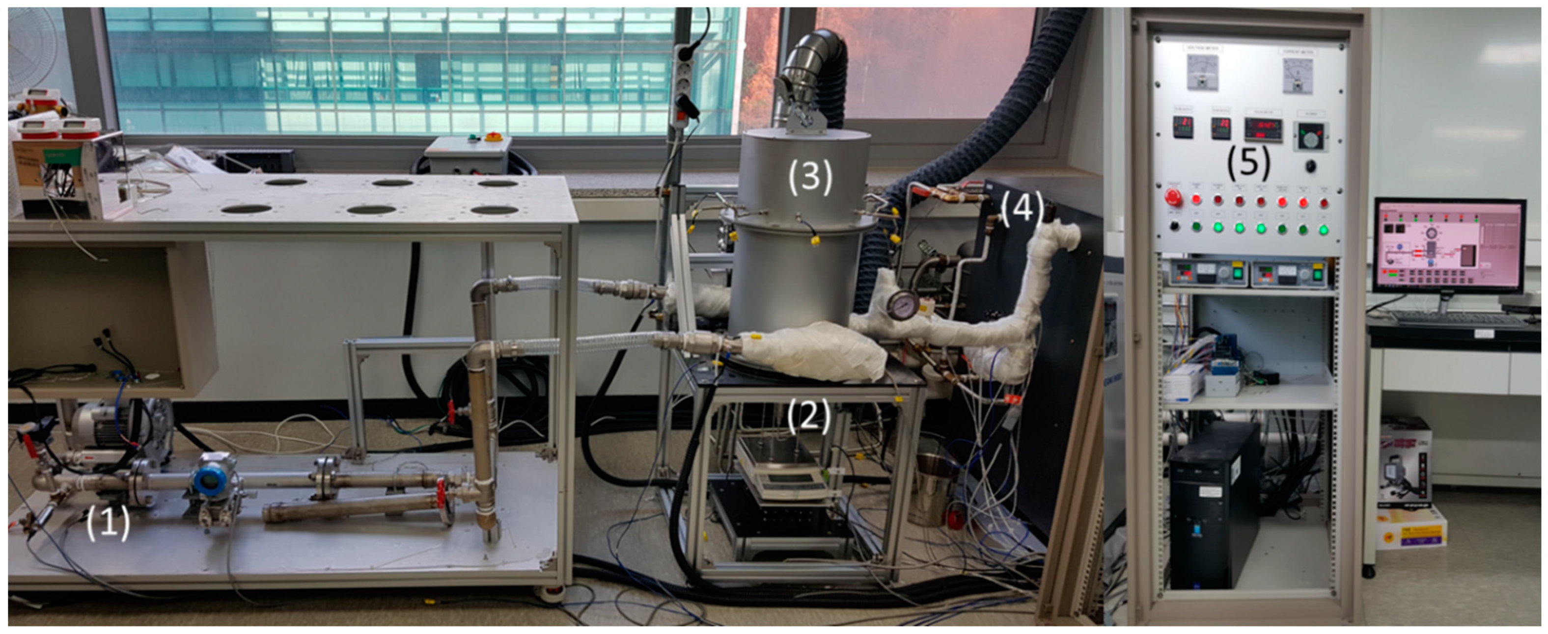
Figure 5.
Photographs of thermochemical heat storage reactor: (a) Heat storage main body, (b) TCM honeycomb cartridge installation, (c) honeycomb cartridge and (d) multiple honeycomb installation in the cartridge.
Figure 5.
Photographs of thermochemical heat storage reactor: (a) Heat storage main body, (b) TCM honeycomb cartridge installation, (c) honeycomb cartridge and (d) multiple honeycomb installation in the cartridge.
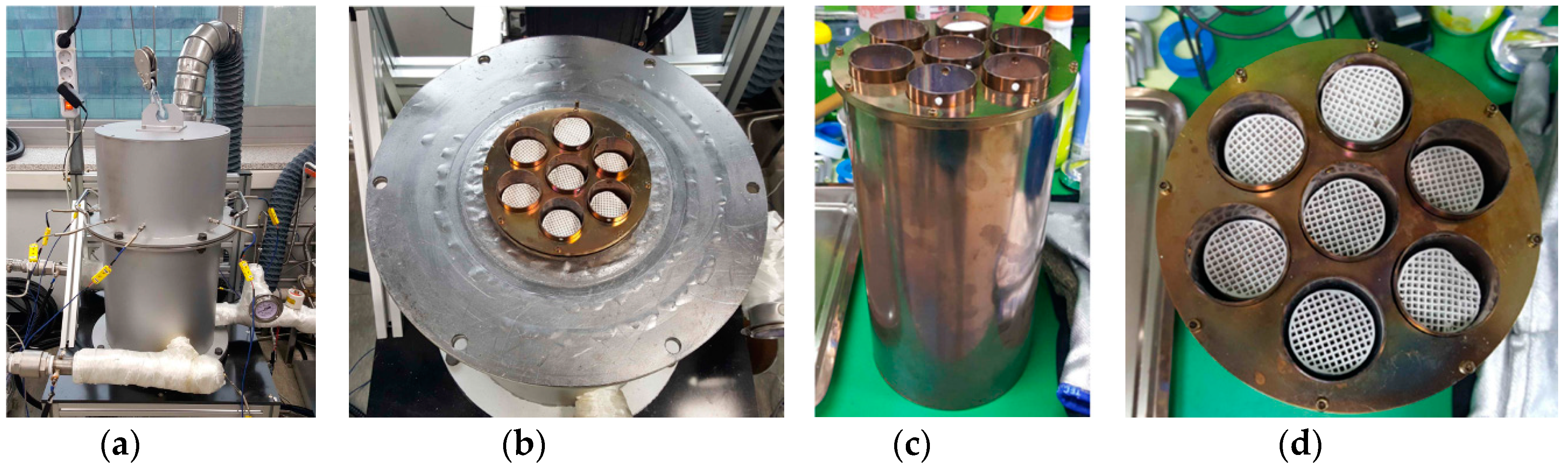
Figure 6.
Heat source, honeycomb inlet and outlet temperature profiles of the long-term cyclic experiment (100 cycles for 555 h) regarding thermochemical heat charging and discharging temperature.
Figure 6.
Heat source, honeycomb inlet and outlet temperature profiles of the long-term cyclic experiment (100 cycles for 555 h) regarding thermochemical heat charging and discharging temperature.
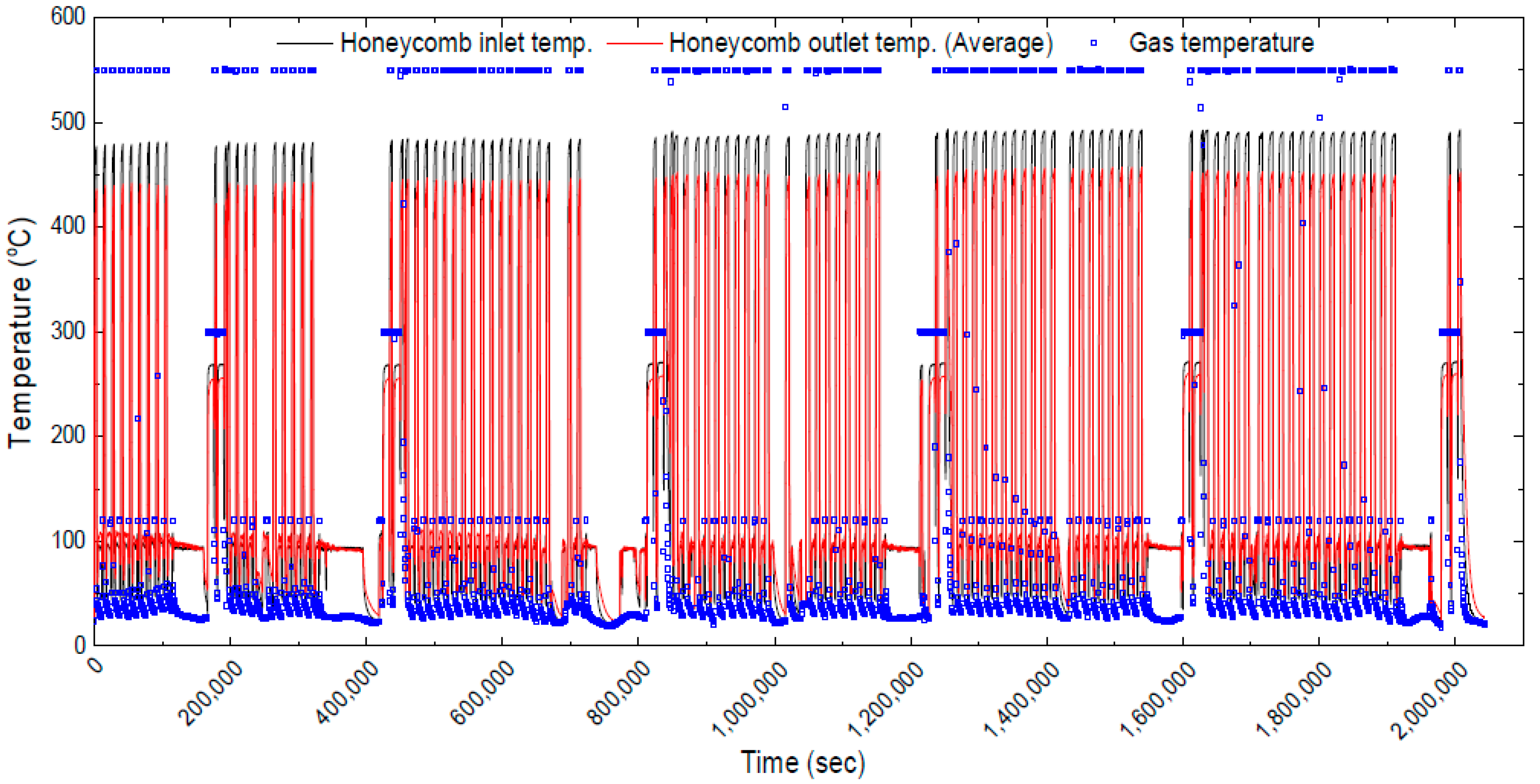
Figure 7.
Honeycomb compressive strength depending on zeolite contents: (a) Before debinding and (b) after debinding.
Figure 7.
Honeycomb compressive strength depending on zeolite contents: (a) Before debinding and (b) after debinding.

Figure 8.
Temperature and gas flow rate profiles of (a) thermochemical with sensible and (b) sensible only heat charging: (1) Gas supply temperature, (2) honeycomb inlet temperature, (3)–(9) Honeycomb-1 to Honeycomb-7 outlet temperatures and (10) inlet gas flow rate.
Figure 8.
Temperature and gas flow rate profiles of (a) thermochemical with sensible and (b) sensible only heat charging: (1) Gas supply temperature, (2) honeycomb inlet temperature, (3)–(9) Honeycomb-1 to Honeycomb-7 outlet temperatures and (10) inlet gas flow rate.
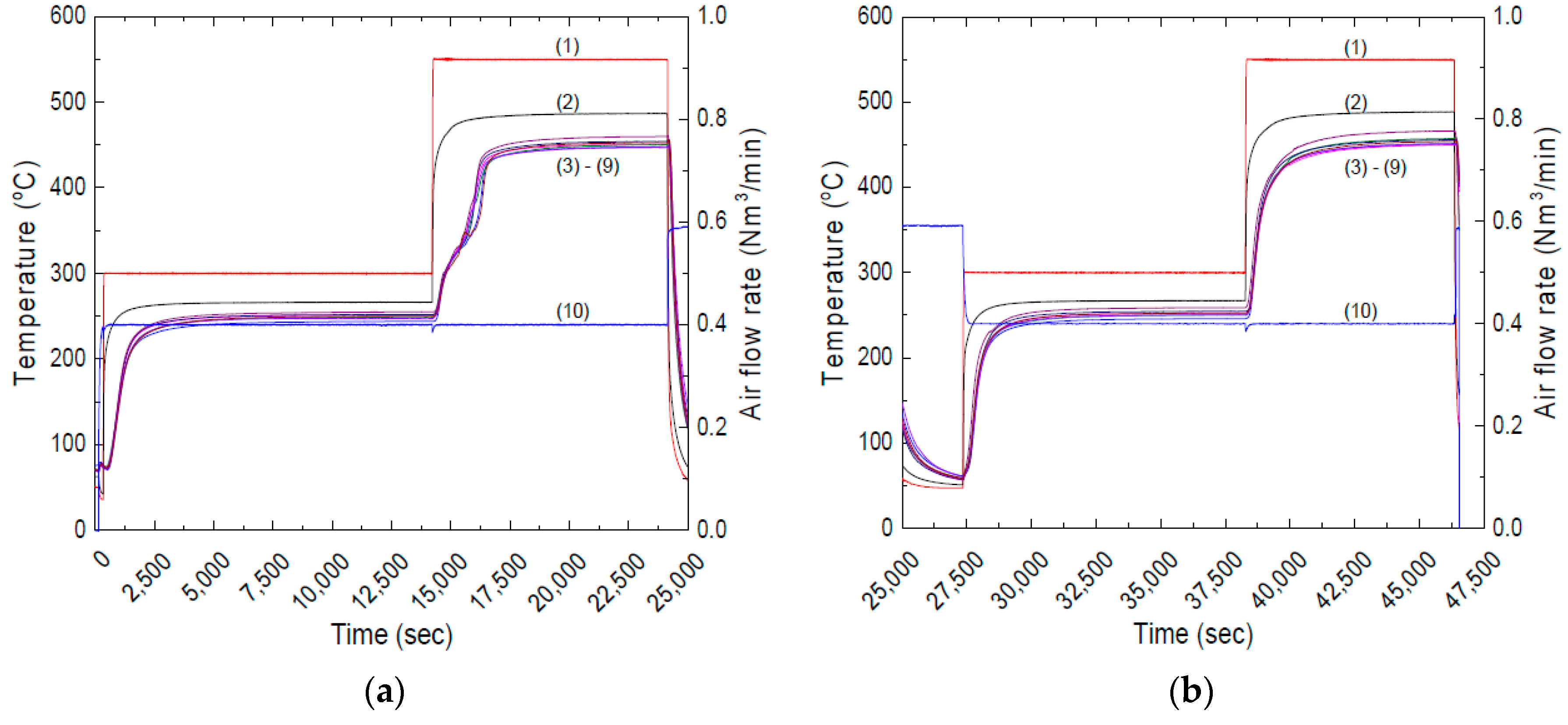
Figure 9.
Analyzing inlet and outlet temperatures between thermochemical & sensible and sensible-only charging, and the amount of thermochemical heat charging from (a) Honeycomb-1, (b) Honeycomb-2, (c) Honeycomb-3, (d) Honeycomb-4, (e) Honeycomb-5, (f) Honeycomb-6, (g) Honeycomb-7 and (h) Comparing the instantaneous thermochemical heat charging of each honeycomb and its location.
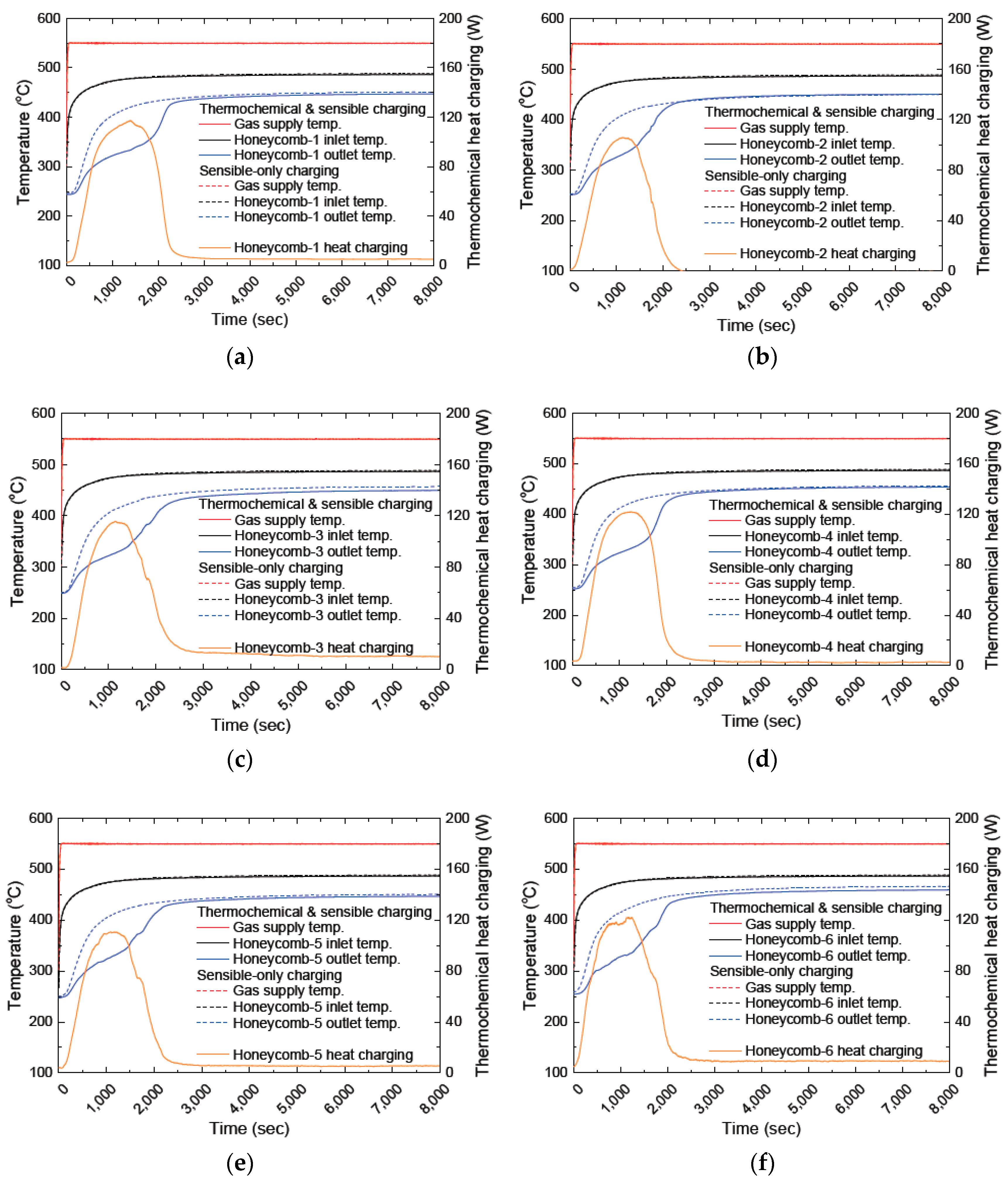

Figure 10.
Numerical modeling and simulation of heat charging process: (a) Temperature profiles of honeycombs in longitudinal direction and (b) velocity profiles of honeycombs in longitudinal direction.
Figure 10.
Numerical modeling and simulation of heat charging process: (a) Temperature profiles of honeycombs in longitudinal direction and (b) velocity profiles of honeycombs in longitudinal direction.

Figure 11.
Internal behavior of heat charging process from numerical modeling and simulation of heat charging process: (a) Temperature contours and (b) velocity contour with vectors.
Figure 11.
Internal behavior of heat charging process from numerical modeling and simulation of heat charging process: (a) Temperature contours and (b) velocity contour with vectors.
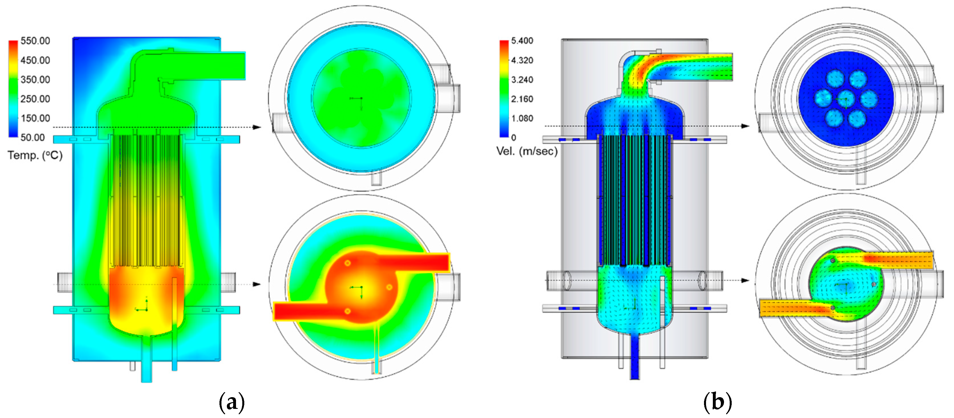
Figure 12.
Differential scanning calorimeter (DSC) graphs for seven honeycombs before and after 100 cyclic test: (a) Heat flow of before cyclic test, (b) heat storage capacity of before cyclic test, (c) heat flow after cyclic test and (d) heat storage capacity after cyclic test.
Figure 12.
Differential scanning calorimeter (DSC) graphs for seven honeycombs before and after 100 cyclic test: (a) Heat flow of before cyclic test, (b) heat storage capacity of before cyclic test, (c) heat flow after cyclic test and (d) heat storage capacity after cyclic test.

Figure 13.
Time series of heat discharging behavior: (a) Thermochemical heat discharging rate and (b) the highest temperature rise in each cycle during heat discharging process.
Figure 13.
Time series of heat discharging behavior: (a) Thermochemical heat discharging rate and (b) the highest temperature rise in each cycle during heat discharging process.
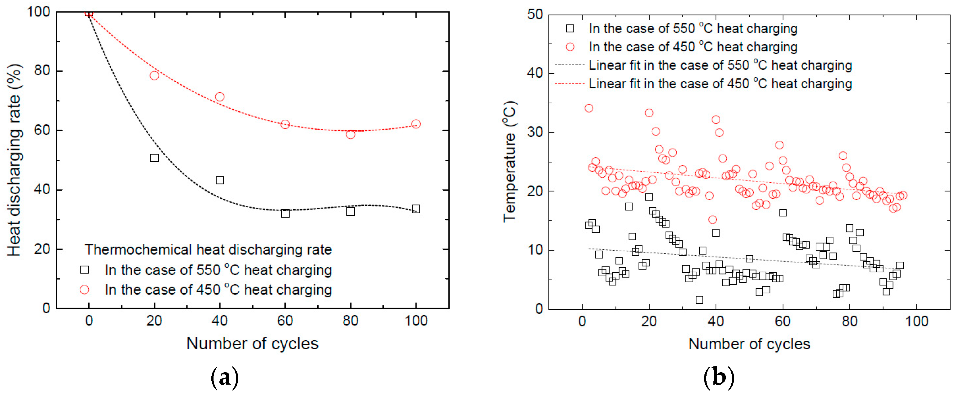
Figure 14.
XRD patterns of honeycomb-1 after fully discharged state in the case of 550 °C heat charging: (a) after one cycle and (b) after 100 cycles.
Figure 14.
XRD patterns of honeycomb-1 after fully discharged state in the case of 550 °C heat charging: (a) after one cycle and (b) after 100 cycles.
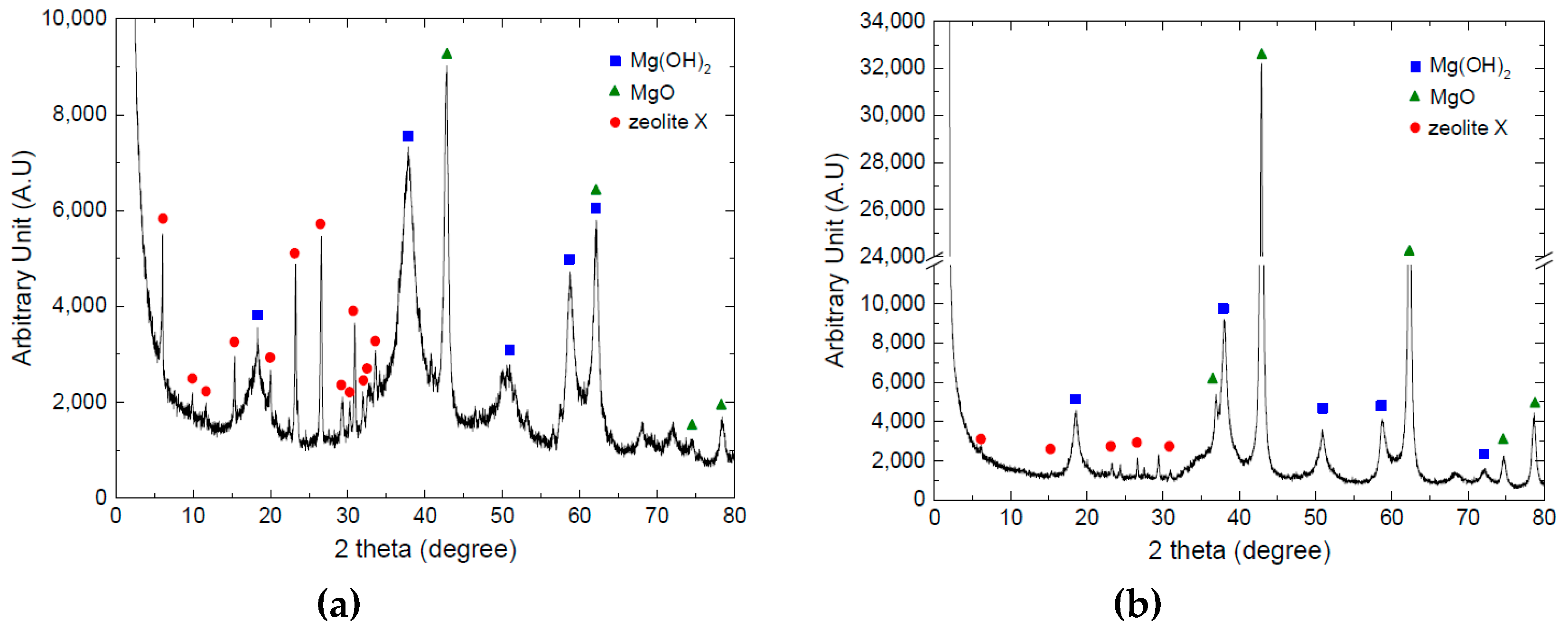
Figure 15.
Honeycomb inlet and outlet temperature profiles during heat discharging cycle of 550 °C heat charging: (a) At the beginning and (b) at the end.
Figure 15.
Honeycomb inlet and outlet temperature profiles during heat discharging cycle of 550 °C heat charging: (a) At the beginning and (b) at the end.

Table 1.
Heat charging–discharging cycle procedure: Equipment status and time table for each step.
| Step | Process | Gas Supply | Reactant Supply | Gas Heater | Steam Boiler | Time (min) |
|---|---|---|---|---|---|---|
| 1 | Stabilizing the gas flow for preparing heat charging | On | Off | Off | Off | 5 |
| 2 | Heat charging—dehydration | On | Off | On | Off | 90 |
| 3 | TCM cooling down | On | Off | Off | Off | 50 |
| 4 | Optional process—measuring the amount of heat charging by thermochemical reaction | On | Off | On | Off | 90 |
| 5 | Heat discharging—hydration | Off | On | Off | On | 70 |
| 6 | Post drying after heat discharging | On | Off | On | Off | 15 |
Table 2.
Heat charging only by thermochemical reaction.
| Heat Charging Only by Thermochemical Reaction | Number of Honeycomb | ||||||
|---|---|---|---|---|---|---|---|
| 1 | 2 | 3 | 4 | 5 | 6 | 7 | |
| Maximum value of instantaneous reaction (W) | 117.4 | 105.7 | 115.7 | 121.9 | 110.7 | 122.2 | 116.8 |
| Total amount of accumulated reaction (Wh) | 50.8 | 38.7 | 46.9 | 47.1 | 43.1 | 49.3 | 52.7 |
Table 3.
Heat charging density.
| Heat Charging Density (GJ/m3) | Number of Honeycomb | ||||||
|---|---|---|---|---|---|---|---|
| 1 | 2 | 3 | 4 | 5 | 6 | 7 | |
| At the beginning of cycle | 2.06 | 1.96 | 1.90 | 2.00 | 2.15 | 1.99 | 2.11 |
| At the end of cycle | 1.14 | 1.01 | 1.20 | 1.00 | 1.30 | 1.11 | 1.15 |
© 2019 by the authors. Licensee MDPI, Basel, Switzerland. This article is an open access article distributed under the terms and conditions of the Creative Commons Attribution (CC BY) license (http://creativecommons.org/licenses/by/4.0/).
Share and Cite
MDPI and ACS Style
Lee, J.Y.; Yim, T.; Kim, H.J.; Hong, S.; Seo, D.W.; Kim, H.S. Investigation on Long Term Operation of Thermochemical Heat Storage with MgO-Based Composite Honeycombs. Energies 2019, 12, 1262. https://doi.org/10.3390/en12071262
AMA Style
Lee JY, Yim T, Kim HJ, Hong S, Seo DW, Kim HS. Investigation on Long Term Operation of Thermochemical Heat Storage with MgO-Based Composite Honeycombs. Energies. 2019; 12(7):1262. https://doi.org/10.3390/en12071262
Chicago/Turabian StyleLee, Jae Yong, Taesu Yim, Hyouck Ju Kim, Sungkook Hong, Doo Won Seo, and Hong Soo Kim. 2019. "Investigation on Long Term Operation of Thermochemical Heat Storage with MgO-Based Composite Honeycombs" Energies 12, no. 7: 1262. https://doi.org/10.3390/en12071262
Note that from the first issue of 2016, this journal uses article numbers instead of page numbers. See further details here.