Classification and Review of Pump-Controlled Differential Cylinder Drives
by
 , ,
, ,
Søren Ketelsen
1,* ,
,
Damiano Padovani
2,
Torben O. Andersen
1,
Morten Kjeld Ebbesen
2 and
Lasse Schmidt
1 1
Fluid Power and Mechatronic Systems, Department of Energy Technology, Aalborg University, 9220 Aalborg, Denmark
2
Department of Engineering Sciences, University of Agder, 4879 Grimstad, Norway
*
Author to whom correspondence should be addressed.
Energies 2019, 12(7), 1293; https://doi.org/10.3390/en12071293
Submission received: 28 February 2019
/
Revised: 26 March 2019
/
Accepted: 1 April 2019
/
Published: 4 April 2019
(This article belongs to the Special Issue Energy Efficiency and Controllability of Fluid Power Systems 2018)
Abstract
:Pump-controlled hydraulic cylinder drives may offer improved energy efficiency, compactness, and plug-and-play installation compared to conventional valve-controlled hydraulic systems and thus have the potential of replacing conventional hydraulic systems as well as electro-mechanical alternatives. Since the late 1980s, research into how to configure the hydraulic circuit of pump-controlled cylinder drives has been ongoing, especially in terms of compensating the uneven flow requirements required by a differential cylinder. Recently, research has also focused on other aspects such as replacing a vented oil tank with a small-volume pressurized accumulator including the consequences of this in terms of thermal behavior. Numerous references describe the advantages and shortcomings of pump-controlled cylinder drives compared to conventional hydraulic systems or electro-mechanical drives. This paper presents a throughout literature review starting from the earliest concepts based on variable-displacement hydraulic pumps and vented reservoirs to newer concepts based on variable-speed electric drives and sealed reservoirs. By classifying these drives into several proposed classes it is found that the architectures considered in the literature reduce to a few basic layouts. Finally, the paper compares the advantages and shortcomings of each drive class and seek to predict future research tasks related to pump-controlled cylinder drives.
1. Introduction
With an increased industrial focus on energy efficiency, plug-and-play installation, and compactness, conventional valve-controlled hydraulic cylinder drives are increasingly being replaced by electro-mechanical alternatives, such as roller or ball screws [1], especially for small power classes. This happens despite the well-known advantages of hydraulic linear actuation such as large force/power densities, reliability, and robustness. Hydraulic actuation is, however, still the preferred solution for many applications such as industrial presses, large mobile machinery, crane manipulators, primary aircraft control etc. [2,3,4]. Among other reasons this is due to certain limitations for the electro-mechanical alternatives, such as limited reliability (e.g., shock loads damage), the difficulties of implementing overload/failure protection and/or limited force capabilities [5,6,7]. To strengthen the position regarding these applications and to make hydraulic cylinder drives competitive with electro-mechanical drives for low power applications, there is a need to enhance both the energy efficiency and the overall flexibility of hydraulic cylinder drives.
The flexibility of a hydraulic system may be related to how power is being distributed between the prime mover and the actuator(s). As illustrated in Figure 1, at least three different power distribution topologies exist: hydraulic, mechanical, and electrical distribution.
In conventional hydraulic systems a centralized hydraulic power unit (HPU) delivers power to all actuators through a common pressure rail (CPR). Each actuator is controlled by a throttling valve, leading to significant losses. To enhance the energy efficiency, the resistive losses associated with throttling must be reduced. A main challenge is to achieve this with preserved controllability at a justifiable cost level. Examples of improving the energy efficiency and maintaining the CPR counts the so-called digital hydraulics where the proportional valve is replaced by multiple on/off valves [8,9,10,11,12] and hydraulic transformers, namely throttleless control devices that replace control valves. The latter is investigated in [13,14,15], where the variable INNAS floating cup transformer is considered, see Figure 1a. Conversely, for a conventional constant hydraulic transformer unit this is investigated in [16]. Hydraulic transformers can be considered as a retrofit solution to conventional systems, as only the control element is replaced while the hydraulic power supply, the common pressure rail and the cylinder remain unchanged. Because the piping is preserved, the flexibility of the system is not significantly improved and so these systems cannot be considered an alternative to electro-mechanical cylinder drives.
Another approach for reducing throttle related losses is represented by pump-controlled cylinder drives. Here the motion of the cylinder is controlled by varying the flow delivered by the pump. Since the pump is used as the control element, a pump is needed for each actuator, which necessitates a complete redesign of the system architecture but also enables the avoidance of the common pressure rail. If a single prime mover is used to drive multiple variable-displacement pumps each controlling a single actuator, the power distribution may be considered mechanical, see Figure 1b. This approach has been of particular interest in mobile machinery, where the internal combustion engine (ICE) acts as the only prime mover. Because the hydraulic pumps are mounted on the same shaft, substantial piping may still be required to each cylinder.
The highest level of flexibility and compactness is achieved if power is distributed electrically and each cylinder is equipped with an individual pump and electric motor. This is especially the case if the conventional vented oil tank is replaced by a sealed accumulator, meaning that only an electrical and mechanical machine interface is present. This aids to the flexibility and compactness of the solution because hoses and pipes related to having a centralized HPU are avoided. For this reason, some researchers also use the term decentralized or zonal hydraulics. These self-contained or compact electro-hydraulic drives are aiming at combining the energy efficiency and flexibility of electric drives while retaining the reliability and force capabilities of hydraulic drives. Even for applications with no electric grid connection readily available, such as mobile machinery, it may be profitable to either replace the ICE with an electric machine and batteries (full electrification) [17] or even to generate a local electric grid by connecting an electric generator to the ICE [18]. Generally, pump-controlled systems can recover kinetic or potential energy (e.g., during load lowering). This is a significant difference compared to conventional valve-controlled systems, where energy recovery is generally not possible, due to throttling across the control valve. If a system contains multiple actuators with the ability to share power (e.g., through a common DC-bus), pump-controlled systems may offer increased energy efficiency, not only on an actuator level but also on a system level. The opportunity of sharing power and recovering kinetic and potential energy opens new possibilities for designing "intelligent energy-optimized systems" [19]. This may especially be the case if including energy storage technologies such as batteries, super-capacitors, or fly-wheels. By proper energy management this may be used to minimize the power peaks requiring by the DC-supply [19], or to optimize loading of the ICE enabling reduced fuel consumption and/or downsizing of the prime mover’s rated power.
Compact pump-controlled cylinder drives match the ongoing industrial trend of electrification and countless applications would benefit from a decentralized, energy efficient, compact, and flexible hydraulic drive. Numerous references (e.g., [20,21]) focus on which advantages and disadvantages pump-controlled cylinder drives possess compared to conventional valve-controlled hydraulics or electro-mechanical drives. As will be evident, pump-controlled cylinder drives may be configured in different ways but, so far, no references compare these approaches thoroughly. This paper is creating an overview of system architectures for pump-controlled hydraulic differential cylinder drives found in literature and industry and classifies these into several proposed classes. This is done to compare general advantages and shortcomings between the drive classes instead of each individual system architecture.
The paper is organized in the following way: In Section 3 the classes used to classify the drive architectures are presented, while Section 4 presents the literature review. Section 5 identifies which research areas are currently in focus. Also, future research topics in order for pump-controlled differential cylinder drives to be valid alternatives to electro-mechanical drives and a valid successor for conventional valve-controlled cylinder drives are proposed. In Section 6 the advantages and shortcomings of the presented classes are summarized and compared. A general introduction to the technology is given in the next section.
2. Overview of Pump-Controlled Differential Cylinder Drives
According to the definition made in this paper, a pump-controlled differential cylinder drive consists of a differential cylinder, a hydraulic supply, an oil reservoir, and auxiliary components which may include valves for safety functions, load-holding, and flow-balancing components. This is illustrated in Figure 2. In the literature these drives are also denoted as self-contained or compact electro-hydraulic/hydrostatic actuators, direct-driven hydraulics, valveless/throttleless actuators etc.
For pump-controlled differential cylinder drives to be valid alternatives to both electro-mechanical drives and conventional valve cylinder drives for general applications, capability of four-quadrant operation is required. Figure 3 exemplifies how a compact pump-controlled differential cylinder drive capable of four-quadrant operation may be designed [2,22]. The hydraulic supply consists of a single fixed-displacement pump connected to a variable-speed electric machine. The reservoir is sealed, and the so-called inverse shuttle valve needed for uneven flow compensation may be regarded as an auxiliary component.
In quadrant Q, the fluid is pumped into the piston side chamber. Due to the asymmetry of the cylinder, a larger flow is required by the piston chamber than the flow leaving the rod side chamber. This differential flow (or rod volume flow) is supplied from a sealed accumulator, through the inverse shuttle valve, which is passively actuated to connect the low-pressure chamber of the cylinder with the accumulator. The accumulator is usually pressurized to a couple of bars (1–3 bar), as a low-pressure leakage line is required for common pump types such as commercially available internal gear pumps [23], external gear pumps [24,25,26] and axial piston pumps [27,28].
In quadrant Q the piston is retracting under a resistive load, causing the rod side chamber to be at a higher pressure than the piston side chamber. This causes the inverse shuttle valve to change position compared to Q and connects the piston chamber with the accumulator. The additional flow leaving the piston side chamber is thus guided to the accumulator. In Q and Q the load is resistive, so power is being supplied to the drive, while in Q and Q the load is aiding the piston motion. In these quadrants the hydraulic pump works in motoring mode, and a potential of recovering some of the energy supplied by the external load is present.
The research emphasis was initially on symmetric actuators controlled by variable-displacement pumps. This concept was already examined by [29] in 1967. The PhD dissertation from [30] from the late 1970s is one of the first references dealing thoroughly with pump-controlled double rod cylinder drives. Initial effort was placed on characterizing the dynamical behavior of variable-displacement pumps, to assess their applicability as primary control elements [31,32,33]. In [34] these are found to be well suited for primary control tasks, while in [35,36] it was pointed out that the dynamics of variable-displacement pumps is generally inferior compared to a conventional control valve. Later [37] found that pump control bandwidths above 45 Hz are achievable and [38] experimentally found closed loop pump control bandwidths of 80 Hz. These results are confirmed in [39], who also concludes that the "commonly found prejudice that pump-controlled systems suffer from slow dynamics of the servo pump used as a final control element are not justified." As pointed out in [40] such dynamic behavior is generally reserved for custom-built pumps e.g., used for research purposes or special applications. Commonly used pumps exhibit much slower control dynamics. Displacement-controlled actuators have been investigated intensively in relation to mobile machinery. For example, in [41] it was found that for controlling the working hydraulics in a 5 ton excavator, a pump bandwidth of 15–20 Hz at ±10% displacement is required. This result is generalized to other larger displacement-controlled mobile applications and it is concluded that a pump bandwidth of 15–20 Hz satisfies even the most strenuous frequency requirements.
The advances within power electronics and electric servo drives enabled using variable-speed electric drives in combination with fixed-displacement pumps for primary control of hydraulic double rod cylinders, which facilitated electrical power distribution instead of hydraulic distribution [42]. Based on thermal considerations, the improved energy efficiency compared to valve-controlled systems, further enhanced the possibility of reducing the oil volume compared to conventional valve cylinder drives. This led to the development of the electro-hydraulic actuator (EHA), characterized by having a pressurized sealed oil reservoir (accumulator) instead of a vented tank. During the 1990s the EHA emerged in the aircraft industry, and are now used for primary flight control in e.g., the Airbus A340 and A380, [2,42].
Due to increased cost and size, the use of double rod cylinders is limited in other industries, where the preferred linear actuator is the differential cylinder [2,43]. Using a single rod cylinder leads to unequal flow rates required by the cylinder chambers. The main focus has therefore been on developing and investigating system architectures capable of compensating this flow difference. A variety of different methods has been proposed. Roughly speaking, the focus on differential cylinders in combination with variable-displacement pumps started in the late 1980s, while the combination of differential cylinders and variable-speed drives can be traced back to the mid-1990s. Compact or self-contained (i.e., using a sealed accumulator) differential cylinder drives emerged around 2010.
3. Classification of Pump-Controlled Differential Cylinder Drives
As mentioned previously pump-controlled cylinder drives may be able to recover energy, and thus offers new opportunities in terms of designing energy-optimized systems, by incorporating power-sharing and energy storage. It is generally important to recognize that the hydraulic drive is part of a bigger system, meaning that to optimize energy consumption of the system, it may not be sufficient to optimize energy consumption on an individual drive level. It is, therefore, always necessary to take into account in which system the drive is included to select and design the actuator best suited for the task. This paper, however, focuses on classifying and reviewing pump-controlled systems on a drive level, e.g., not considering in which context the cylinder drive or actuator is used. This is done even though the authors recognize that it may not be fair to directly compare pump-controlled hydraulic drives optimized for different applications. On a general level, it is however assessed that main advantages and drawbacks for different circuit architectures is identifiable.
A drive classification may generally be performed on different detail levels. To focus on main functionality and to keep the number of classes reasonable, a high level classification is proposed. As an example a drive may be classified based on whether the used hydraulic pump is a fixed or variable-displacement type (higher level), or more specific which machine topology is used, e.g., axial/radial piston, internal/external gear etc. (lower level). Similarly, a drive may be classified based on whether a constant-speed or variable-speed prime mover is used (higher level), or specifically whether e.g., an asynchronous induction, a switched reluctance or a permanent magnet synchronous machine is used (lower level).
The lower level classification is relevant during the design phase for a specific application, but counterproductive when obtaining an overview concerned with the main functionality. A system classification based on main hardware components and their configuration is therefore proposed. As such, only a classification of the basic system architectures is within the scope of the paper. Such classifications have previously been presented in various publications. In [47] the authors distinguished between valve compensated and pump compensated circuits, while [48] presented a basic classification of architectures using two pumps, based on the configuration of the pumps. In [22] a classification also including single-pump solutions and different auxiliary components needed for uneven flow compensation was presented. The classification proposed in this paper, is closely related to the one presented in [22], however the type of hydraulic supply (variable-displacement or speed-variable pumps) is included in the following. This extension is made to assess how the chosen type of hydraulic supply affects the performance characteristics of the pump-controlled cylinder drive.
Figure 4 shows the classes emerging when classifying the pump-controlled cylinder drives based on: hydraulic supply (type and number of prime movers and hydraulic pumps), circuit architecture (open or closed) and uneven flow compensation method. A circuit architecture is said to be open if one of the pump ports is always being connected to a reservoir/accumulator. This means that oil leaving a cylinder chamber is not able to enter the other chamber in all four operating quadrants without entering a reservoir first. An open-circuit architecture normally does not require a four-quadrant pump. A closed-circuit architecture requires at least one four-quadrant pump, i.e., some of the oil may be pumped directly from one-cylinder chamber to the other, without passing the reservoir, thus constituting a closed circuit.
The classification is based on the following delimitations:
- The classes based on variable-speed electric drives combined with variable-displacement hydraulic pumps are omitted in this classification due to the lack of research efforts and the higher cost. It is however likely that a higher energy efficiency is obtainable [42,49,50], meaning that future pump-controlled cylinder drives may be based on this approach.
- The classification only includes the use of one or two prime movers, as none of the considered publications deal with more prime movers.
- The classes based on two constant-speed prime movers are not considered because this is only relevant for dimensioning considerations. The general functioning of the drive does not change compared to using a single prime mover, because the control functionality is handled by the variable-displacement pump(s).
- Classes based on two variable-speed prime movers in combination with a single hydraulic pump are omitted, because this architecture is functionally similar to single variable-speed prime mover and single-pump classes.
Additional components to handle the uneven cylinder flow are needed for the classes based on a single pump (A and E). Some suggestions are shown in the green (functional) classes A.1 to A.3 and E.1 to E.3. For multiple-pump hydraulic supplies (class B, C, D) uneven flow compensation may be realized without the need for additional components.
Based on the hydraulic supply class only, the above considerations lead to five main classes (A to E) and 13 functional sub-classes, shown as green boxes in Figure 4. The classification leads to a limited number of basic system architectures, whereas numerous different varieties of these basic architectures may be derived to obtain specific characteristics needed for a given application (or family of applications). The specific architectures may include auxiliary components such as load-holding and safety valves, oil filter, cooler etc., and the chosen reservoir type (sealed or vented).
Please note that the distinction made between variable-displacement and variable-speed hydraulic supplies increase the functional solution groups compared the e.g., the classification made in [22]. It is however important to emphasize that the solution space for the architectures in e.g., class A is exactly the same as for class E, because the only difference is the method of controlling the pump flow. The same is true for classes B.1, C.1, D.1 and B.2, C.2 and D.2. Some flow compensation methods are however more suitable for some classes. For example, even though the hydraulic transformer solution is only listed for class E, this would also be functional for class A.
4. Reviewing and Classifying the State-of-the-Art
In the following sub-sections, a literature review is conducted, and the identified systems are classified into the classes proposed in Figure 4.
4.1. Class A—Single Variable-Speed Prime Mover and Single Pump
Class A drives work by controlling the rotational direction and speed of a variable-speed electric machine connected to a single fixed-displacement pump. As the cylinder chamber flows are uneven, additional components are needed to compensate this difference to avoid cavitation or/and excessive pressure build up. In general, class A drives are characterized by a simple hydraulic circuit only requiring a small number of components and a relatively low control complexity due to a rather constrained system as only a single input is generally present. This also leads to a general inability to control the pressure of the non-load-carrying chamber, resulting in the low-pressure chamber being close to the accumulator/tank pressure. This causes the overall drive stiffness to be low, decreasing the eigenfrequency of the drive which may lead to positioning inaccuracy [51] and unsatisfying dynamic performance of the drive e.g., at impact loads.
The contributions identified in the literature for the sub-classes A.1 to A.3 are presented in the following. Open-circuit variable-speed architectures using directional control valves in the main transmission lines (pump to cylinder) have not been found in the literature. For open-circuit displacement-controlled drives, however, a few examples are shown in Section 4.5.3. These architectures would also be feasible in combination with open-circuit single-pump variable-speed supplies.
4.1.1. A.1—Passive Valves
A simple solution to compensate uneven cylinder flows using a flushing/inverse shuttle valve was patented in [52], see Figure 5a. The inverse shuttle valve connects the low-pressure cylinder chamber to the reservoir to compensate the uneven cylinder flow. In aided load situations, the hydraulic pump and the electric machine work in motoring and generator mode respectively, meaning that a potential for recovering energy exists. Recently the inverse shuttle valve solution has been given renewed attention, possibly because of the appealing simplicity of this configuration consisting of rather few and simple components [2,22]. The drive however suffers from undesired shuttle valve oscillations (so-called mode oscillations) for certain load cases (switching loads). This rather complicated phenomenon is occurring when the equilibrium point for the system is close to the switching pressure of the inverse shuttle valve. If the system is poorly damped, the valve switching condition is met, while moving towards the equilibrium point. Due to the cylinder asymmetry, this causes the structure of the system to change, in turn causing the equilibrium point to move compared to before the valve switch [53]. The repetition of this process (potentially a limit cycle) is responsible for undesired pressure and piston motion oscillations. Investigation of the mode oscillation issue has been addressed by multiple researchers, see. e.g., [47,54,55,56,57,58].
One of the proposed solutions to counteract this undesirable behavior, is to use an under-lapped inverse shuttle valve. This has experimentally proved to reduce the tendency of mode oscillation, at the expense of throttling losses, and thus lower energy efficiencies [54,55]. The acceleration limits to avoid mode oscillations for large inertia loads have been investigated in [21], and the authors experimentally showed that these limits may be calculated to avoid oscillatory operation if the load is known.
Another known disadvantage of this drive is the inability to control the pressure of the non-load-carrying chamber, resulting in the low-pressure chamber being close to the accumulator/tank pressure. This causes the overall drive stiffness to be low, which negatively affects the dynamic properties of the drive. An additional charge pump can be used to avoid low-pressure operation [55]. This generally has a negative impact on compactness, flexibility, reliability, and energy efficiency.
In [59] it is proposed to use counter balance valves for load-holding purposes (blue components in Figure 5a), at the expense of not being able to regenerate energy. Compared to the to the system in Figure 5c [60], simulation results suggest an energy saving of 57% when used to control the position of aircraft seats. The system in Figure 5c also contains load-holding valves not shown in the figure, and uses a passively actuated directional control valve, to guide the additional oil flow from the piston side to the accumulator during retraction.
As an alternative to the inverse shuttle valve, two pilot-operated check valves may be used (Figure 5b), which has been investigated intensively for displacement-controlled actuators (Class E). This system is functionally very similar to the inverse shuttle valve solution, and suffers from the drawbacks regarding mode oscillations and low-pressure operation. Commercial products based on the pilot-operated check valve solution has been introduced lately by Bosch Rexroth AG [45,61]. In [3] the authors proposed to include a passive load-holding subsystem (Blue components in Figure 5b) for actuating a single link crane manipulator. The load-holding subsystem passively holds the load in case of emergency e.g., power shutdown but it may also be enabled by the operator during standstill to enhance energy efficiency. For a given test trajectory an energy efficiency of 60% is obtained experimentally.
To address the mode oscillation issue [40] introduced two counter balance valves and a low-pressure charge pump. By a clever sizing of the counter balance valves, significant throttling losses are only present when the chamber pressure difference is small, which is critical regarding mode oscillation, while the throttling losses are insignificant when the pressure difference is larger. This is experimentally shown to yield oscillation free performance at critical loads, while the energy efficiency is not affected for non-critical loads. The oscillation free operation comes at a cost of an increased energy consumption of 12% for a specific operation cycle.
Another approach for compensating the uneven cylinder chamber flows is used by Parker Hannifin [44] in their commercially available EHA, shown in Figure 5d. The EHA is available in a power range up to 560 W [44]. Dependent on the piston motion, a passively actuated directional control valve guides oil to/from the cylinder whenever the rod side pressure exceeds the piston side pressure. A pressure-relief valve inserted between the reservoir and the directional valve elevates the pressure in the non-load-carrying chamber, (back pressure), to ensure drive stiffness during piston motion. For this reason, Parker Hannifin denotes the combination of the directional valve and the pressure-relief valve a "back pressure valve". A closely related concept is also found in [62].
4.1.2. A.2—Active Valves
The pump-controlled drive visible in Figure 5e was investigated in a two-quadrant tote dumper application in [63]. An electrically actuated 2/2-way on/off valve is used to direct oil from the piston side chamber to the vented tank during retraction, while this valve is closed during cylinder extension. Load-holding is achieved using a counter balance valve, which is found to prohibit the circuit to work in motoring mode and thus precludes energy recovery during load lowering. A test showed decreased energy consumption of 21% compared to a valve-controlled system for a given load cycle.
A comprehensive analysis of the mode oscillation issue known from passive valve compensated architectures was conducted in [47]. Based on this analysis a rather simple switching logic for the flow compensating valves counteracting mode oscillation issues is derived. This switching logic may be realized using an actively controlled 4/3-way directional valve as shown in Figure 5g or using architectures based on hydraulically/passively actuated valves. Experimental results for the latter are however not presented. Beside the circuit shown in Figure 5g experimental results for circuits using an additional pressurized flow supply to elevate chamber pressures and to deliver the compensation flow are presented. The experimental work is conducted on a backhoe loader performing a pendular motion (four-quadrant operation) and the results showed that by using the proposed valve switching logic mode oscillations did not occur independent of the operation condition, i.e., there are no critical regions or critical loads leading to mode oscillations. This solution is not restricted to variable-speed architectures but may also be incorporated in variable-displacement architectures.
4.1.3. A.3—Asymmetric Pump
By redesigning the valve plate of a conventional axial piston pump, an asymmetric unit with three independent ports has been designed and tested [64,65,66,67]. This 3-port pump solution was also disclosed in a patent application [68]. The two ports connected to the cylinder chambers may be constructed with a displacement ratio that matches the cylinder area ratio, meaning that no additional components are needed for flow compensation. The third port is connected to a low-pressure line. This is shown in Figure 5f. Fundamentally, the asymmetric pump-controlled cylinder drive is similar to a drive comprising of two fixed-displacement pumps connected on the same shaft. However, there might be a slight advantage in terms of compactness in favor of the asymmetric pump drive. Also, a better energy efficiency of the asymmetric pump drive compared to the double pump solution have been reported, which may be due to reduced frictional losses as only a single pump instead of two needs to be driven [43]. Compared to a separate-meter-in-separate-meter-out (SMISMO) valve-controlled system, energy savings of 75% have been reported for a given load cycle when implemented in a mini excavator [69].
4.2. Class B—Variable-Speed Single Prime Mover with Multiple Pumps
Instead of using auxiliary components to compensate the uneven flow (Class A), a fundamentally different approach is to handle the uneven flow problem by the hydraulic supply itself, i.e., using multiple pumps. Compared to the valve solutions in class A, this approach has the advantage of ideally not requiring the use of additional valves for uneven flow compensation. This is especially advantageous due to the absence of mode oscillations. Class B systems are characterized by using simple hydraulic components in a simple hydraulic architecture. The main drawback is the inherent low-pressure operation.
The usage of two oppositely oriented pumps in an open-circuit configuration (Figure 6a) has been investigated by multiple researchers. Here the uneven cylinder flows are compensated by the pumps, as the displacement ratio of the pumps ideally matches the cylinder area ratio. However, as pointed out by [70], anti-cavitation valves and pressure-relief valves are generally required, because the pressure dependent pump leakages make it impossible to achieve proper matching of the pump displacement ratio and the cylinder area ratio under all operating conditions. To limit a potential pressure increase [70] uses two proportional valves shown as the blue components to bleed off oil to the reservoir. These valves are not included in this setup by other researchers.
For actuating a single link boom [71] reported lifting efficiencies around 55%. The sizing error of the displacement ratio of the pumps related to the cylinder area ratio is assessed to reduce the energy efficiency of the system. To address this, a hydraulic accumulator may be connected to the non-load-carrying chamber. This is found to increase efficiencies as much as 30 percentage points for this two-quadrant lifting/lowering operation [72].
To enhance compactness the conventional oil reservoir has been replaced by a pressurized accumulator by several researchers, e.g., in [1,73,74]. In [75] the authors investigated how to install such a compact hydraulic drive on the links of a small excavator. In particular, the focus is on evaluating how the additional weight originating from the compact drives affect the energy efficiency and the stresses in the boom structure. Simulation results suggested an increased energy consumption of 11–17%. A structural analysis furthermore showed that the original boom structure is safe. In [76] lifting efficiencies ranging from 67% to 77% are simulated for the same excavator.
To avoid low-pressure operation, which is an inherent feature of the double pump configuration [77,78] added a third pump which is only active in the forward direction, see Figure 6c. Using advanced control functionality, it is possible to control the pressure level (i.e., the minimum chamber pressure) and thus the drive stiffness during motion. Experimental verification shows energy efficiencies ranging from 18% to 51% in four-quadrant operation. A simulation study shows an energy saving potential of 60% compared to a conventional valve-controlled system for actuation of a two-link middle-sized knuckle boom crane for a representative load cycle [79].
The two pumps may also be configured in a closed-circuit architecture, as seen in Figure 6b, offering smaller pump sizes compared to open-circuit architectures at the expense of requiring a closed-circuit pump. Early focus on this concept and variable-speed drives in general is found in [51] from 1997. Here the main advantage compared to variable-displacement drives (Class D/E) is pointed out to be improved efficiency especially at part loads and avoidance of an additional pressure source needed to control the variable-displacement pump. For the pumps available at that time it is highlighted that to enhance the reliability these needed to be optimized for low speed operation.
In [51] the investigation was based on a vented tank configuration (Figure 6b) finding that the drive stiffness impacts severely on the positioning accuracy. In [2,22] the vented tank was replaced with a pressurized accumulator and the authors experimentally compared this drive with an electro-mechanical counterpart. This investigation showed similar energy efficiencies and compactness, superior robustness towards impact loads and overload protection but inferiority regarding drive stiffness due to low-pressure operations. This architecture was investigated for actuating the six cylinders of a Stewart platform used for flight simulations in [80]. The evaluated energy consumption was between 25% to 50% of a conventional valve-controlled system. This is partly achieved by connecting an extra accumulator to the rod side, rendering the possibility of passively carrying the static load of the platform by cleverly pre-charging the two accumulators, which ideally results in zero torque on the prime mover’s shaft in static situations. This also increases the drive stiffness, but requires an additional charging/discharging circuit [81].
4.3. Class C—Two Variable-Speed Prime Movers and Multiple Pumps
Including a second variable-speed prime mover enables the possibility of controlling an additional state, often chosen to be a pressure state, to avoid low-pressure operations. Beside the possibility of avoiding low-pressure operations, class C drives are characterized by being highly scalable. This also results in a higher cost, compared to single prime mover classes for the same power output demands. Furthermore, the control complexity generally increases as two independent inputs need to be controlled.
In the closed-circuit architecture (Figure 7b) both prime movers operate simultaneously in motor or generator mode, contrary to the open-circuit architecture (Figure 7a) where one prime mover works as a motor while the other acts as a generator. This means that the closed-circuit architecture is more scalable as larger output powers may be delivered for the same electric motor sizes. The open-circuit solution is briefly presented in [43,51], but neither in-depth analyses nor experimental testing have been published for this architecture.
The closed-circuit architecture (Figure 7b) has been investigated in [82,83,84,85,86], and a 64 kW drive has been experimentally tested in an injection molding machine, with clamping forces up to 1600 kN and max rod velocities of 0.8 m/s (not simultaneously). In [48] this concept is investigated with focus on different multi-variable control concepts and a closed position control loop and closed chamber sum-pressure loop strategy is implemented, yielding a constant chamber sum pressure, to keep the drive stiffness high. The reference speed for the electric machines is a (scaled) sum of the controller output, constituting a static decoupling of the input-output couplings. In this work it is furthermore shown that using a variable-speed, variable-displacement drive does not improve energy efficiency compared to a variable-speed fixed-displacement approach, for a considered injection molding machine case.
Finally, no architectures using more than a single pump connected to each electric machine have been identified.
4.4. Class D—Single Constant-Speed Prime Mover and Multiple Pumps
Instead of using variable-speed fixed-displacement drives, variable-displacement constant-speed hydraulic units may be used. This approach is in some sense the predecessor of the variable-speed approach, as the variable-displacement pump was investigated as a primary control element for cylinder drives before variable-speed electric drives were economically and dynamically feasible. The main focus on variable-displacement differential cylinder drives is related to mobile machinery.
Most attention has been given to single-pump displacement-controlled drives (Class E), whereas the focus on using two pumps for each cylinder has been limited. This is probably due to this solution being cost-intensive and requiring advanced control methods, which is infeasible for cost-sensitive applications such as mobile machinery [87].
The open-circuit solution (Figure 8a) has been presented in [81,88] investigated this concept in a 0.6 MN forging press. A decentralized position and rod side pressure chamber control method has been adopted. The positioning accuracy and forging rapidity was found to improve when increasing the rod side chamber pressure (increased drive stiffness). The energy consumption of the press however remained almost unchanged. The high cost of the variable-displacement pumps compared to valve-controlled drives is pointed out to be a challenge for the market penetration of this technology.
The closed-circuit architecture (Figure 8b) is found in [89], where emphasis was placed on investigating suitable control strategies. Two different control methods were suggested, both aiming at controlling the cylinder motion and at keeping a certain pressure level. The first approach only required piston position feedback and included a hydraulically actuated pressure level valve, guiding oil from a charge source to the cylinder chambers if the pressure sum is lower than some preset value. The second approach did not require an additional valve but was based on multi-variable control techniques, thus requiring both piston position and chamber pressure feedback signals.
In [90] the closed-circuit architecture (Figure 8b) was used to actuate a hydraulic broaching machine and reduced the energy consumption with 55% compared to a conventional valve system for a given load cycle. A similar concept is also observed in a patent application [91].
Using three variable-displacement main pumps enables the opportunity to circulate oil, ideally without affecting neither cylinder motion nor pressure levels. This may be advantageous in relation to ensure proper oil filtration and cooling [92]. However, no references concerned with three or more variable-displacement main pumps have been identified, which may be due to this solution being rather expensive.
4.5. Class E—Single Constant-Speed Prime Mover and Single Pump
As mentioned in the previous section the focus on using multiple variable-displacement pumps is limited. Conversely, using a single variable-displacement pump has obtained significant attention. As with the single pump arranged in the variable-speed fixed-displacement configuration (Class A), additional components are needed to handle the uneven cylinder flows. The investigated solutions are quite similar to the methods used for class A, because the fundamental challenge is similar. The differences between class A and E concerns the requirement of a low displacement charge pump, which conventionally is needed to control the displacement setting of the main pump. The charge pump is often also used to elevate the chamber pressures yielding a higher drive stiffness. Including the charge pump and the control circuit for the main pump generally leads to a larger complexity of the hydraulic circuit and to a higher system cost compared to variable-speed drives.
4.5.1. E.1—Passive Valves
Using a pilot-operated check valve for flow compensation in uneven cylinder drives for two-quadrant operation was suggested in [33]. The pilot-operated check valve was used to connect the cylinder chamber with a vented reservoir, which inherently led to low-pressure operation and reduced stiffness. This idea has been modified into the architecture shown in Figure 9a where a charged low-pressure line is connected to the cylinder chambers using pilot-operated check valves [93,94,95,96]. The low-pressure line is generated by a fixed-displacement pump and generally needed for controlling the displacement of the main pump, to compensate system leakages, avoiding cavitation at the inlet port of the main pump and recirculating oil for filtration and cooling. Additionally, this increases the chamber pressure levels and thus stiffness. The circuit in Figure 9a has been intensively researched from the end of the 1990s, especially regarding mobile machinery where a combustion engine is used to drive the working hydraulics. Some varieties in terms of including the load-holding functionality exist. In some references, no load-holding functions are included, in others load-holding is achieved by electrically actuated on/off valves (Figure 9a), while [97] included the load-holding capability using hydraulically actuated logic elements. The main drive functionality however remains the same.
The architecture is especially well suited for multiple actuator mobile machinery because they can share the same low-pressure charge line. In [87,98,99] the drive architecture was implemented on a multi-link mobile crane and on a wheel loader respectively, and in both cases fuel savings of 15% compared to a conventional load sensing system was reported.
Fuel savings of more than 40% have been reported when implemented in a multiple actuator small excavator compared to a conventional load sensing system. This leads to lower working temperature, downsized combustion engines and reduction or potential elimination of the cooling requirements [100,101,102,103]. The authors in [104,105] suggested pump sharing between multiple actuators to decrease the overall cost of the hydraulic system. Further activities have been related to mode oscillation (similar to what was seen in Section 4.1.1) [106], active oscillation damping [107,108] and thermal modelling [109,110].
In [56,57] a solution that makes use of an inverse shuttle valve for flow compensation (Figure 9c) was investigated, and special attention was given to investigate mode oscillations. By adding additional leakage using two electrically actuated 2/2-way valves (Figure 9c) mode oscillations are found to be suppressed at the expense of throttling losses across these valves.
4.5.2. E.2—Hydraulic Transformer
In [33] it is proposed to use a hydraulic transformer to compensate the uneven cylinder flows, as illustrated in Figure 9b. In [89,111] the author investigated the hydraulic transformer as a flow compensation device and derived six feasible ways of connecting the hydraulic transformer with a variable-displacement pump, the cylinder, and the reservoir. Two of these configurations were combined using a switching valve (see Figure 9d) to switch between a high speed and a high force mode. The solution suffers from being unable to match the cylinder flow needs under all operating conditions due to pressure dependent leakage. In [89] it was suggested to use a variable-displacement charge pump in combination with a sum of pressure control valve to address this while [81] recommended involving a variable-displacement transformer (illustrated with a dotted arrow in Figure 9d). As pointed out by [81], since a conventional hydraulic transformer is "bulky, heavy and complex", it makes these solutions "less appealing when compared to other solutions". Innovative transformer technologies may be able to change this, e.g., the variable INNAS floating cup transformer which is significantly more compact, as only a single rotating machine (with three ports in the valve plate) is used instead of two rotating machines [13].
4.5.3. E.3—Directional Control Valves
For single-pump open-circuit architectures, directional valves in the main transmission lines (between pump and cylinder) are needed to accommodate four-quadrant operation. One approach is shown in Figure 9e where the two directional valves connect the cylinder chambers with the reservoir, unless the pressure on the pump side exceeds the chamber pressure. This means oil leaving the cylinder chambers is directed to the reservoir disabling the opportunity for energy recovery. This architecture is briefly presented in [2] without any further examination.
A more elaborate architecture combining the advantages of pump-controlled cylinder drives with the advantages of separate metering valves is shown in Figure 9f. This architecture is characterized by controlling the piston motion in different modes dependent on the positions of the four 2/2 valves. This expands the operating region (force and speed) compared to single-pump closed-circuit solutions [112]. For example, is the cylinder piston retracting speed not limited by the pump size in aided load situations, because oil may also be guided to the other cylinder chamber (differential lowering) or directly to the reservoir (meter out flow control) [113]. This is a significant advantage in relation to some mobile machinery where the lowering speed is often demanded to be twice as high as the lifting speed [114]. Using the proposed architecture, the pump may be downsized compared to equivalent closed-circuit architectures. The challenges for this architecture are related to the control of pump and valves required for smooth transition between operation mode and quadrant [112,115]. In [113] fuel savings of 10% to 20% compared to a conventional load sensing hydraulic system was achieved, when implemented in a wheel loader. Using a closely related architecture in a 300 ton mining excavator [116] investigated a closely related open-circuit concept and simulated fuel savings of 28% compared to a conventional system.
5. Current and Future Research Topics
As mentioned in the introduction the industrial breakthrough for pump-controlled differential cylinder drives is yet to come. For these drives to be attractive compared to both electro-mechanical alternatives and conventional valve cylinder drives the qualities of both these technologies need to be combined. This means that pump-controlled cylinder drives must be comparable to electro-mechanical cylinder drive technologies in relation to:
- Energy efficiency including energy recovery
- Compactness (Self-contained system)
- Only electrical and mechanical (machine) interface
Furthermore, pump-controlled differential cylinder drives must be comparable to conventional valve cylinder drives in relation to:
- Scalability/application range
- Fluid management (cooling, filtration)
- Drive stiffness
- Reliability and durability
- Safety functionality
Based on the literature review research has previously been focused on identifying system architectures capable of compensating uneven cylinder flows and the implementation in specific applications. Architectures meeting all above requirements have not been identified. Therefore, such a system architecture is a natural focus for future research.
When considering compact and sealed hydraulic drives, one of the major challenges is the significantly reduced oil amount compared to conventional systems. This causes the oil filtration and cooling to be handled differently to avoid the conventional use of an additional subsystem connected to the oil tank to manage the fluid condition.
An attractive idea is the complete avoidance of both the cooling and filtration elements. This would enhance compactness of the system, but would also require the energy losses of the system to be balanced only by the passive heat transfer to the surroundings, to keep the oil and component temperature within acceptable ranges. This has led to research concerned with thermal modelling and temperature investigation of pump-controlled cylinder drives [110,117,118,119,120]. In [121], experimental results for a compact pump-controlled system equivalent to the system in Figure 5a, reveal oil temperatures above 70 C, at indoor working conditions if no oil cooler is used. For standard hydraulic components and fluids this may be beyond limits, which may cause reduced durability and reliability. On the contrary [122] tests a pump-controlled system running with oil temperatures below 0 C, sometimes experienced by mobile machinery in the Scandinavian countries, Canada, Russia etc. The investigation shows drastically decreased efficiencies at lower temperatures. Furthermore, significant differences are observed for the two different types of working fluids included in the study. No investigation into how operating with very low oil temperatures affects the wear and reliability of the system is included.
Investigation and modelling of thermal behavior, sizing and layout of an oil cooling/heating methodology (either passive or active) is therefore an important research area to ensure durability and reliability of pump-controlled cylinder drives.
Another attractive idea is the avoidance of an oil filter, which may be possible due to the sealed nature of a compact drive. As such, only self-contamination will be present in the fluid, as external contamination is ideally absent. Additionally, if oil is treated within design range (e.g., temperature), lifespan oil filling may be possible. For the architecture depicted in Figure 6b, [123] found that after 960 hours of operation, the self-contamination, especially originating from the beginning of the test, resulted in a high particle load. This leads to the observation that operating a compact pump-controlled cylinder drive is currently not recommended without an oil filter, at least when using a standard HLP 46 hydraulic fluid. Another potential research field is therefore investigation of more suitable working fluids (e.g., oils specifically designed for self-contained systems).
As pointed out by [92], most pump types are not able to continuously run at low rotational speeds (<300 RPM). Running at low speed may reduce reliability and durability. None of the considered architectures can circulate oil, without affecting cylinder motion. Therefore, it may be beneficial to consider architectures permitting this function. Oil circulation ability may also be appropriate for filtration and cooling purposes.
6. Classification Summary
From the literature review it is found that research has primarily been focused on classes A, B, and E, compared to the classes with two control elements (i.e., class C and D). Taking the release date of the literature into consideration it seems that the focus on variable-displacement drive architectures is declining and almost exclusively is related to mobile machinery.
The interest for variable-speed and compact architectures is broad-based across both stationary hydraulics and mobile machinery. This is assessed mainly to be related to a lower cost, a better energy efficiency, and a simpler hydraulic circuit compared to variable-displacement drives. Furthermore, no variable-displacement architectures using a sealed, low volume accumulator have been identified in the literature, which may be due to the difficulties of reducing the oil volume due to significant and constant energy losses. This generally affects the applicability of variable-displacement systems compared to variable-speed drives, as a trend towards compact and self-contained solutions is occurring. This tendency may also be explained by the general industrial focus on electrification, as this favors variable-speed technology due to the control functionality being handled by electric components (i.e., frequency converters) instead of hydraulic control valves.
To summarize the findings of the review process, the drive classes are compared based on the eight criteria listed below. Even though cost is an important parameter, it is chosen not to consider this criterion because it is too difficult to assess and compare the cost between the classes as this is heavily affected by the specific components selected to meet the requirements of a given application. The same is true for the experienced acoustic noise levels of the drive classes. The drive acoustics are highly dependent on the chosen pump type and whether an internal combustion engine (only class D and E) or electrical prime mover is used. An advantage for class A, B, and C drives is that significant acoustic noise is only present during motion of the cylinder piston.
Energy efficiency
For all drive classes a significantly reduced energy consumption compared to conventional valve-controlled systems has been reported. In general, variable-speed drives (Class A, B, C) are reported to achieve a better part load efficiency [42,51,82,124] compared to variable-displacement drives. For variable-displacement drives (Class D and E) a small fixed-displacement charge pump is often used, which is assessed to reduce the overall energy efficiency. Using a variable-displacement charge pump may improve energy efficiency but it yields a more complicated and cost-intensive hydraulic system. At piston standstill (i.e., no power output) energy is still consumed by both the variable-displacement and variable-speed approaches due to inherent losses. For the classes based on variable-speed electric drives these losses originates from the torque generated by the fixed-displacement pumps in turn causing electric losses even though the load is kept stationary. Because common fixed-displacement pump types, are not recommended to be operated at low pump speeds, it may be necessary to circulate the oil, i.e., maintain a non-zero pump speed even at cylinder piston standstill, which is associated with losses. To circumvent this, components such as pilot-operated check valves, overcenter valves, or counterbalance valves well known from safety-critical conventional cylinder drives may be used.
Also, for variable-displacement drive classes (Class D and E) significant input energy is required at standstill. Especially the pump losses i.e., volumetric, mechanical, and churning losses accounts for this. The term churning losses are used to describe the losses associated with the rotating components stirring the oil during operation of a piston pump, and they increase with increasing rotational speed [125]. For axial piston pumps published data from the manufacturers Eaton and Parker Hannifin show that the energy consumption at zero delivery/zero stroke conditions for large pressure differences may be over 10% of the input energy required at full flow [126,127,128].
Ability to control drive stiffness
For classes based on a single variable-speed prime mover (A and B) it is generally not possible to control the drive stiffness/pressure level under all operating conditions. So far, this problem has not been solved without including an additional charge source. The authors in [78] succeeded in controlling the drive stiffness for a single variable-speed prime mover architecture, but only during motion of the cylinder piston. If two prime movers are used (class C), multiple researchers used this additional degree-of-freedom to control a pressure state as well as the cylinder motion to attain a reasonable drive stiffness. For variable-displacement drives (Class D and E), most solutions use a low-pressure charge pump which maintains chamber pressures at an elevated level.
Ability to handle highly dynamic/switching loads
The ability to keep the drive stiffness at a reasonable level improves the ability to handle highly dynamic loads. Furthermore, transition issues, known as mode oscillations, have been reported for most class A and E drives at certain load cases.
Concerning oscillation reduction and active vibration damping, which are important aspects for modern hydraulic drives, the dynamic performance/control bandwidth of the pump flow is important. As reported by several researchers, e.g., [39] the bandwidth of the pump displacement adjustment system (class D and E), is dominated by the characteristics of the pump-controlled valve and it is possible to achieve small-signal bandwidths above 80 Hz [38]. As mentioned previously, the authors in [40] argues that such bandwidths are reserved for custom-built pumps, and that commonly available pumps exhibit much slower control dynamics. Therefore, the achievable bandwidth is highly dependent on the chosen components.
The same is so to speak true for the variable-speed drive classes (class A, B, and C). An investigation from 2002 [48], shows velocity control bandwidths around 5 Hz (small signal) for standard induction motors controlled by a frequency converter. For other motor types (e.g., switched reluctance or AC servomotors) the small-signal control bandwidth is found to be significantly higher, approximately 30-40 Hz. In [129], a small-signal bandwidth of 120 Hz is experimentally verified for an industrially available permanent magnet synchronous machine controlled by a frequency converter.
Furthermore, achievable bandwidths are assessed to be highly dependent on control components (valves and frequency converters) and controller tuning. The above however shows that high control bandwidths are achievable for all drive classes. The upper limit is assessed to be the highest for custom-built variable-displacement pumps (class D and E), because high-end servo valves with very high dynamic capabilities may be used if necessary.
Drive compactness and flexibility
Drive compactness depends on the number and configuration of the components. Based on the high-level classification considered here, it is difficult to compare compactness for each drive class, as this is heavily affected by the specific components chosen during a design phase. For the same power output, the size of an asynchronous induction machine is generally larger than a comparable permanent magnet synchronous machine. However, it is generally assumed that using two prime movers (class C) reduces the achievable compactness compared to single prime mover classes.
Concerning flexibility of the drive classes, the architectures based on electric machines for each cylinder drive (Class A, B, and C) are assessed to be highly flexible due to the possibility of plug-and-play-installation.
Hydraulic circuit simplicity
It is generally assumed that the multiple-pump classes are simpler than single-pump classes, as additional components and fluid paths are needed to compensate uneven flows. Furthermore, it is assumed that using variable-displacement pumps increases the complexity of the hydraulic circuit, as such pumps conventionally are electro-hydraulically actuated.
Control simplicity
In general, hydraulic drives are characterized by non-linearities and uncertainties, and the control complexity is heavily affected by the requirements set by a specific application. This means that closed loop control structures may be arbitrary involved for all drive classes. However, it may be generally assumed that the control complexity increases as the number of inputs increases. This is justified by a simple observation: It is relatively easy to control the piston motion in single input systems (class A, B and E) in an open loop manner. The operator basically just needs to guide oil into the cylinder chamber he desires to supply. For the multiple input classes (C and D) this is not sufficient, as the operator must also control the amount of oil leaving the other chamber. Furthermore, optimizing a complex control algorithm is generally more challenging than optimizing a simple one. The performance of architectures requiring complex algorithms may therefore be affected significantly by a poor control design.
Reliability
Long term evaluation of the reliability of pump-controlled drives is limited in the literature. Some investigations were conducted around the year 2000 concerning the reliability of different types of variable-speed pumps [48]. A 1000 h test cycle was performed, and the results indicated that some pump types (i.e., radial piston pump) did not show any significantly wear after 1000 h of operating. In fact, the efficiency of the radial piston pump improved after 1000 h of operation [48]. For other pumps types (axial piston pumps and internal gear pumps) the efficiency is seen to be unaffected or slightly decreased. Visual inspection shows some cavitation related damages (e.g., grooves) for both pump types.
Due to the recent increased industrial interest in variable-speed pumps, these may have been improved in relation to variable-speed operation. Therefore, the results in [48] may be outdated. However, data sheet information reveals that some pump types are not recommended for continuous low speed operation. Whether this is due to the manufacturers not having tested the pumps at continues low speed or if this really implies a reduced reliability is unknown. For constant-speed variable-displacement drives it is however clear that all components are used within recommended range. This also includes oil temperatures and contamination levels as cooling and filtration are done by offline subsystems similar to conventional systems. As mentioned for compact variable-speed pump-controlled cylinder drives, it is challenging to filter and cool the oil sufficiently to keep oil temperature within a prescribed range. Given the information currently available it is assumed that the reliability of variable-displacement drives is expected to be superior compared to the variable-speed drive classes. However, consistent research and industrial focus is needed to assess the reliability thoroughly.
Degree of scalability
The degree of scalability is primarily decided by the available components, rather than by the drive class. For the basic architectures, valves are primarily only used for uneven flow compensation meaning that these are not assessed to limit scalability. As a result, the limiting factor in terms of power is assessed to be either the (electric) prime mover or the pump.
For variable-displacement drives, the prime mover would normally be an internal combustion engine or a synchronous induction machine running at grid frequency, which offer a wide power range. The used pump is normally chosen as a variable piston pump, which also offer a wide power range. Axial piston pumps with power outputs of more than 500 kW can be purchased as standard components.
For variable-speed drive classes, a variety of different options are available, and the component choices rather depend on the application than on the drive class. In general, asynchronous induction machines offer a wider power range than e.g., permanent magnet synchronous machines, while the dynamic capabilities are superior for the latter. Similarly, external gear pumps generally offer a narrower operating range compared to e.g., internal gear units or piston pumps, but they are more cost-effective. If the same type of components is chosen, it is obvious that the dual prime mover class C configured in a closed-circuit architecture offers a larger power output than the single prime mover classes (class A and B).
Table 1 provides a synthesis of the mentioned criteria where each drive class has been graded. The grades are as follows, (- -), (-), (+), (+ +), with (- -) being the worst.
7. Conclusions
Conventional valve-controlled linear hydraulic actuation systems are notoriously known for large force/power densities, reliability, and robustness. A main drawback is however a low energy efficiency, much lower than electro-mechanical counterparts, such as roller or ball screws. To improve the energy efficiency of hydraulic systems it is, therefore, required to reduce throttling losses. One approach for doing so, is represented by so-called pump-controlled cylinder drives. This paper presents a review of different architectures found in research literature, industrial catalogues, and patent applications. Common for these modern system architectures is that the control valve is omitted and that the motion of the cylinder is controlled directly by the pump flow, thus requiring at least one pump per actuator. To obtain an overview, the identified architectures are classified into several proposed classes, and it is found that if considering main functionality, the architectures considered in literature reduce to a few basic layouts only.
The review reveals that compared to valve-controlled systems, significant energy savings are obtainable. Some references report energy savings up to 75% for specific applications. Furthermore, a trend towards the architectures based on electrical prime movers rather than combustion engines is spotted, which is found to match the industrial focus on electrification well. This is furthermore supported by the observation that pump-controlled cylinder drives are generally able to recover energy and share power between multiple actuators. This facilitate designing energy-optimized systems by incorporating proper energy management on a system level, and thus pump-controlled cylinder drives may play an important role in future hydraulically actuated applications.
The main challenges for the market penetration of the technology and thus obvious focus for future research, is assessed to be related to thermal issues and drive controllability. As such, newer references are focusing on replacing the vented oil tank with a small pressurized accumulator, to enhance compactness. This may give rise to oil temperatures beyond limits, which would negatively impact performance and reliability. Related to drive controllability, some system architectures suffer from a low drive stiffness. This is found to affect positioning accuracy and control bandwidths negatively, thus making these system designs inappropriate for applications requiring high control bandwidths and positioning accuracies.
Author Contributions
Conceptualization, S.K., D.P., L.S. and T.O.A.; methodology, S.K.; investigation, S.K.; resources, S.K., D.P. and L.S.; writing—original draft preparation, S.K.; writing—review and editing, S.K., D.P., L.S., T.O.A., M.K.E.; visualization, S.K.; supervision, L.S., T.O.A., M.K.E.; funding acquisition, T.O.A.
Funding
This research was funded by the Research Council of Norway, SFI Offshore Mechatronics, project number 237896/O30.
Conflicts of Interest
The authors declare no conflict of interest.
References
- Brahmer, B. CLDP—Hybrid Drive using Servo Pump in Closed Loop. In Proceedings of the 8th International Fluid Power Conference, Dresden, Germany, 26–28 March 2012; pp. 93–102. [Google Scholar]
- Weber, J.; Beck, B.; Fischer, E.; Ivantysyn, R.; Kolks, G.; Kunkis, M.; Lohse, H.; Lübbert, J.; Michel, S.; Schneider, M.; Shabi, L.; Sitte, A.; Weber, J.; Willkomm, J. Novel System Architectures by Individual Drives. In Proceedings of the 10th International Fluid Power Conference, Dresden, Germany, 8–10 March 2016; pp. 29–62. [Google Scholar]
- Padovani, D.; Ketelsen, S.; Hagen, D.; Schmidt, L. A Self-Contained Electro-Hydraulic Cylinder with Passive Load-Holding Capability. Energies 2019, 12, 292. [Google Scholar] [CrossRef]
- Frischemeier, S. Electrohydrostatic actuators for aircraft primary flight control-types, modelling and evaluation. In Proceedings of the 5th Scandinavian International Conference on Fluid Power, SICFP ’97, Linköping, Sweden, 28–30 May 1997; pp. 1–16. [Google Scholar] [CrossRef]
- van den Bossche, D. The A380 Flight Control Electrohydrostatic Actuators, Achievements and Lessons Learnt. In Proceedings of the ICAS 25TH International Congress of the Aeronautical Sciences, Hamburg, Germany, 3–8 September 2006; pp. 1–8. [Google Scholar]
- Mare, J.C. Combining Hydraulics and Electrics for Innovation and Performance Improvement in Aerospace Actuation. In Proceedings of the 12th Scandinavian International Conference on Fluid Power, Tampere, Finland, 18–20 May 2011; pp. 255–270. [Google Scholar]
- Hagen, D.; Pawlus, W.; Ebbesen, M.K.; Andersen, T.O. Feasibility Study of Electromechanical Cylinder Drivetrain for Offshore Mechatronic Systems. Model. Identif. Control A Nor. Res. Bull. 2017, 38, 59–77. [Google Scholar] [CrossRef]
- Hedegaard Hansen, A.; Pedersen, H.C. Optimal configuration of a discrete fluid power force system utilised in the PTO for WECs. Ocean Eng. 2016, 117, 88–98. [Google Scholar] [CrossRef]
- Hedegaard Hansen, A.; F Asmussen, M.; Bech, M.M. Energy optimal tracking control with discrete fluid power systems using model predictive control. In Proceedings of the Ninth Workshop on Digital Fluid Power, Aalborg, Denmark, 7–8 September 2017. [Google Scholar]
- Hedegaard Hansen, A.; F Asmussen, M.; Bech, M.M. Model Predictive Control of a Wave Energy Converter with Discrete Fluid Power Power Take-Off System. Energies 2018, 11, 635. [Google Scholar] [CrossRef]
- Linjama, M.; Vihtanen, H.P.; Sipola, A.; Vilenius, M. Secondary Controlled Multi-chamber Hydraulic Cylinder. In Proceedings of the 11th Scandinavian International Conference on Fluid Power, Linköping, Sweden, 2–4 June 2009; pp. 1–15. [Google Scholar]
- Huova, M.; Aalto, A.; Linjama, M.; Huhtala, K.; Lantela, T.; Pietola, M. Digital hydraulic multi-pressure actuator–the concept, simulation study and first experimental results. Int. J. Fluid Power 2017, 18, 141–152. [Google Scholar] [CrossRef]
- Achten, P.A.J. What a Difference a Hole Makes—The Commercial Value of the INNAS Hydraulic Transformer. In Proceedings of the Sixth Scandinavian International Conference on Fluid Power, Tampere, Finland, 26–28 May 1999; pp. 873–886. [Google Scholar]
- Vael, G.; Achten, P.; Potma, J. Cylinder Control with Floating Cup Hydraulic Transformer. In Proceedings of the Eighth Scandinavian Conference on Fluid Power, Tampere, Finland, 7–9 May 2003; pp. 175–190. [Google Scholar]
- Heybroek, K.; Vael, G.; Palmberg, J.O. Towards Resistance-free Hydraulics in Construction Machinery. In Proceedings of the 8th International Fluid Power Conference, Dresden, Germany, 26–28 March 2012; Volume 2, pp. 123–138. [Google Scholar]
- Dluzik, K. Entwiklung und Untersuchung energiesparender Schaltungskonzepte für Zylinderantriebe am Drucknetz. Ph.D. Thesis, RWTH Aachen, Aachen, Germany, 1989. (In German). [Google Scholar]
- Hassi, T.; Korva, A.; Markkula, S.; Paratanen, T.; Sourander, T.; Kiviluoma, P.; Korhonen, A.; Kuosmanen, P. Improving Energy Efficiency of an Electric Mini Excavator. In Proceedings of the 11th International DAAAM Baltic Conference, Tallinn, Estonia, 20–22 April 2016. [Google Scholar]
- Minav, T.; Heikkinen, J.E.; Pietola, M. Direct driven hydraulic drive for new powertrain topologies for non-road mobile machinery. Electr. Power Syst. Res. 2017, 152, 390–400. [Google Scholar] [CrossRef]
- Ristic, M.; Wahler, M. Electrification of Hydraulics Opens New Ways for Intelligent Energy-Optimized Systems. In Proceedings of the 11th International Fluid Power Conference, Aachen, Germany, 19–21 March 2018. [Google Scholar]
- Helbig, A.; Boes, C. Electric Hydrostatic Actuation-modular building blocks for industrial applications. In Proceedings of the 10th International Fluid Power Conference, Dresden, Germany, 8–10 March 2016; pp. 93–102. [Google Scholar]
- Michel, S.; Weber, J. Electrohydraulic Compact-drives for Low Power Applications considering Energy-efficiency and High Inertial Loads. In Proceedings of the 7th FPNI PhD Symposium on Fluid Power, Reggio Emilia, Italy, 27–30 June 2012; pp. 1–18. [Google Scholar]
- Michel, S.; Weber, J. Energy-efficient electrohydraulic compact drives for low power applications. In Proceedings of the ASME/BATH 2012 Fluid Power and Motion Control, Bath, UK, 12–14 September 2012; pp. 93–107. [Google Scholar]
- Rexroth, Bosch AG. Internal Gear Pump PGM Series 4X, RE10235. 2014. Available online: https://md.boschrexroth.com/modules/BRMV2PDFDownload-internet.dll/re10235_2014-09.pdf?db=brmv2&lvid=1182639&mvid=13907&clid=20&sid=77703FE74E26CCE9963705CEDFFFF9EE.borex-tc&sch=M&id=13907,20,1182639 (accessed on 3 April 2019).
- Rexroth, Bosch AG. External Gear Motors. RE 14026. 2005. Available online: https://md.boschrexroth.com/modules/BRMV2PDFDownload-internet.dll/re14026_2009-05.pdf?db=brmv2&lvid=1143155&mvid=13907&clid=20&sid=77703FE74E26CCE9963705CEDFFFF9EE.borex-tc&sch=M&id=13907,20,1143155 (accessed on 3 April 2019).
- Rexroth, Bosch AG. External Gear Pump Series B, RE10088. 2013. Available online: https://md.boschrexroth.com/modules/BRMV2PDFDownload-internet.dll/re10088_2019-01.pdf?db=brmv2&lvid=1210039&mvid=13907&clid=20&sid=77703FE74E26CCE9963705CEDFFFF9EE.borex-tc&sch=M&id=13907,20,1210039 (accessed on 3 April 2019).
- Parker Hannifin. Gear Pumps/Motors Series PGP/PGM Fixed Displacement Pumps, Cast-Iron and Aluminium Designs. Catalogue HY30-3300/UK. Available online: https://www.parker.com/literature/PMDE/Catalogs/Gear_Units/PGP_PGM/HY30-3300-UK.pdf (accessed on 3 April 2019).
- Rexroth, Bosch AG. Axial Piston Units A10FZO, A10VZO and A10FZG, A10VZG Series 10 for variable-speed drives. RE91485. 2016. Available online: https://md.boschrexroth.com/modules/BRMV2PDFDownload-internet.dll/RE91485_2016-10.pdf?db=brmv2&lvid=1199007&mvid=13907&clid=20&sid=77703FE74E26CCE9963705CEDFFFF9EE.borex-tc&sch=M&id=13907,20,1199007 (accessed on 3 April 2019).
- Parker Hannifin. Axial Piston Pumps Series PVplus Variable Displacement, Catalogue MSG30-3245/UK. Available online: http://www.parker.com/Literature/PMDE/Catalogs/Piston_Pumps/PV+/MSG30-3245UK.pdf (accessed on 3 April 2019).
- Merritt, H.E. Hydraulic Control Systems; Wiley: New York, NY, USA, 1967. [Google Scholar]
- Sprockhoff, V. Untersuchungen von Regelungen am hydrostatischen Zylinderantrieb mit Servopumpe. Ph.D. Thesis, RWTH Aachen, Aachen, Germany, 1979. (In German). [Google Scholar]
- Backé, W.; Berbuer, J. Neue Schaltungskonzepte fur hydrostatische Getriebe. Ölhydraul. Pneum. 1987, 31, 518–525. (In German) [Google Scholar]
- Backé, W. Möglichkeiten zur Energieeinsparung in der Hydraulik. In Proceedings of the 11. Aachener Fluidtechnisches Kolloquium, Aachen, Germany, 8–10 March 1994; pp. 201–235. (In German). [Google Scholar]
- Berbuer, J. Neuartige Servoantriebe mit primärer Verdrängersteuerung. Ph.D. Thesis, RWTH Aachen, Aachen, Germany, 1988. (In German). [Google Scholar]
- Hahmann, W. Das Dynamische Verhalten hydrostatischer Antriebe mit Servopumpe und ihr Einsatz in Regelkreisen. Ph.D. Thesis, RWTH Aachen, Aachen, Germany, 1973. (In German). [Google Scholar]
- Backé, W. Hydraulic Drives With High Efficiency. In Proceedings of the International Mechanical Engineering Congress, Fluid Power Systems and Technology, San Francisco, CA, USA, 12–17 November 1995; Volume 2, pp. 45–73. [Google Scholar]
- Backé, W. The present and future of fluid power. Proc. Inst. Mech. Eng. 1993, 207, 193–212. [Google Scholar] [CrossRef]
- Rahmfeld, R.; Ivantysynova, M. New displacement Controlled Linear Actuator Technology—A Suitable Control Element for Active Oscillation Damping. In Proceedings of the Eighth Scandinavian International Conference on Fluid Power, Tampere, Finland, 7–9 May 2003; pp. 1139–1155. [Google Scholar]
- Berg, H.; Ivantysynova, M. Design and testing of a robust linear controller for secondary controlled hydraulic drive. Proc. Inst. Mech. Eng. Part I 1999, 213, 375–386. [Google Scholar] [CrossRef]
- Grabbel, J.; Ivantysynova, M. An Investigation of Swash Plate Control Concepts for Displacement Controlled Actuators. Int. J. Fluid Power 2005, 6, 19–36. [Google Scholar] [CrossRef]
- Imam, A.; Rafiq, M.; Jalayeri, E.; Sepehri, N. Design, Implementation and Evaluation of a Pump-Controlled Circuit for Single Rod Actuators. Actuators 2017, 6, 10. [Google Scholar] [CrossRef]
- Rose, J.; Ivantysynova, M. A Study of Pump Control Systems for Smart Pumps. In Proceedings of the 52nd National Conference on Fluid Power, Las Vegas, NV, USA, 23–25 March 2011; pp. 683–692. [Google Scholar]
- Kazmeier, B. Energieverbrauchsoptimierte Regelung Eines Elektrohydraulischen Linearantriebs Kleiner Leistung Mit Drehzahlgeregeltem Elektromotor Und Verstellpumpe. Ph.D. Thesis, TU Hamburg-Harburg, Hamburg, Germany, 1998. (In German). [Google Scholar]
- Quan, Z.; Quan, L.; Zhang, J. Review of energy efficient direct pump controlled cylinder electro-hydraulic technology. Renew. Sustain. Energy Rev. 2014, 35, 336–346. [Google Scholar] [CrossRef]
- Parker Hannifin. Compact EHA—Electro-Hydraulic Actuators for high power density applications. 2011. Available online: http://www.parker.com/Literature/Hydraulic%20Pump%20Division/Oildyne%20EHA/Compact-EHA-Catalog-HY22-3101E-7-13.pdf (accessed on 3 April 2019).
- Bosch Rexroth AG. SHA Servo-Hydraulic Actuator. 2017. Available online: https://dc-corp.resource.bosch.com/media/general_use/products/industrial_hydraulics_1/systems_1/20170915_Kundeninformation_SHA_EN.pdf (accessed on 3 April 2019).
- Servi Group. Servi Hybrid Drive. Linear Actuator. 2017. Available online: https://www.servi.no/media/documents/Hybrid_Cylinder_1705-1_NO.pdf (accessed on 3 April 2019).
- Costa, G.K.; Sepehri, N. Four-Quadrant Analysis and System Design for Single-Rod Hydrostatic Actuators. J. Dyn. Syst. Meas. Control 2018, 141. [Google Scholar] [CrossRef]
- Neubert, T. Untersuchungen von drehveränderbaren Pumpen. Ph.D. Thesis, TU Dresden, Dresden, Germany, 2002. (In German). [Google Scholar]
- Willkomm, J.; Wahler, M. Potentials of Speed and Displacement Variable Pumps in Hydraulic Applications. In Proceedings of the 10th International Fluid Power Conference, Dresden, Germany, 8–10 March 2016; pp. 379–391. [Google Scholar]
- Willkomm, J.; Wahler, M.; Weber, J. Quadratic Programming to Optimize Energy Efficiency of Speed- and Displacement-Variable Pumps. In Proceedings of the 8th FPNI Ph.D Symposium on Fluid Power, Lappeenranta, Finland, 11–13 June 2014. [Google Scholar] [CrossRef]
- Rühlicke, I. Elektrohydraulische Antriebssysteme mit Drehzahlveränderbarer Pumpe. Ph.D. Thesis, TU Dresden, Dresden, Germany, 1997. (In German). [Google Scholar]
- Hewett, A.J. Hydraulic Circuit Flow Control. U.S. Patent 5,329,767, 19 July 1994. [Google Scholar]
- Williamson, C. Power Management for Multi-Actuator Mobile Machines with Displacement Controlled Hydraulic Actuators. Ph.D. Thesis, Purdue University, West Lafayette, IN, USA, 2010. [Google Scholar]
- Çalışkan, H.; Balkan, T.; Platin, B.E. A Complete Analysis for Pump Controlled Single Rod Actuators. In Proceedings of the 10th International Fluid Power Conference, Dresden, Germany, 8–10 March 2016; pp. 119–132. [Google Scholar] [CrossRef]
- Çalışkan, H.; Balkan, T.; Platin, B.E. A Complete Analysis and a Novel Solution for Instability in Pump Controlled Asymmetric Actuators. J. Dyn. Syst. Meas. Control 2015, 137. [Google Scholar] [CrossRef]
- Wang, L.; Book, W.J.; Huggins, J.D. A Hydraulic Circuit for Single Rod Cylinders. J. Dyn. Syst. Meas. Control 2012, 134, 011019. [Google Scholar] [CrossRef]
- Wang, L.; Book, W.J. Using Leakage to Stabilize a Hydraulic Circuit for Pump Controlled Actuators. J. Dyn. Syst. Meas. Control 2013, 135, 061007. [Google Scholar] [CrossRef]
- Imam, A.; Rafiq, M.; Jalayeri, E.; Sepehri, N. A Pump-Controlled Circuit for Single-Rod Cylinders that Incorporates Limited Throttling Compensating Valves. Actuators 2018, 7, 13. [Google Scholar] [CrossRef]
- Altare, G.; Vacca, A. A Design Solution for Efficient and Compact Electro-hydraulic Actuators. Procedia Eng. 2015, 106, 8–16. [Google Scholar] [CrossRef] [Green Version]
- Altare, G.; Vacca, A.; Richter, C. A Novel Pump Design for an Efficient and Compact Electro- Hydraulic Actuator. In Proceedings of the IEEE Aerospace Conference, Big Sky, MT, USA, 1–8 March 2014. [Google Scholar] [CrossRef]
- Bosch Rexroth AG. Advantages of Electrification and Digitalization Technology For Hydraulics. 2018. Available online: https://www.boschrexroth.com/en/xc/products/product-groups/industrial-hydraulics/the-fitness-program-for-hydraulics (accessed on 3 April 2019).
- Olson, M.; Praazak, J. Electro-Hydraulic Actuator. U.S. Patent 2011/0289912 A1, 2011. Available online: https://patentimages.storage.googleapis.com/11/87/9d/336151787d8fa5/US20110289912A1.pdf (accessed on 3 April 2019).
- Jalayeri, E.; Imam, A.; Tomas, Z.; Sepehri, N. A throttle-less single-rod hydraulic cylinder positioning system: Design and experimental evaluation. Adv. Mech. Eng. 2015, 7. [Google Scholar] [CrossRef] [Green Version]
- Quan, L.; Yang, Y.; Hou, X. Simulation and experimental research on the axial piston pump with series three-windows in valve plate. In Proceedings of the 2011 International Conference on Fluid Power and Mechatronics, Beijing, China, 17–20 August 2011; pp. 71–76. [Google Scholar] [CrossRef]
- Zhang, X.; Quan, L.; Yang, Y.; Wang, C.; Yao, L. Output characteristics of a series three-port axial piston pump. Chin. J. Mech. Eng. 2012, 25, 498–505. [Google Scholar] [CrossRef]
- Huang, J.; Quan, L.; Zhang, X. Development of a dual-acting axial piston pump for displacement controlled system. Proc. Inst. Mech. Eng. Part B 2013, 228, 606–616. [Google Scholar] [CrossRef]
- Huang, J.; Zhao, H.; Quan, L.; Zhang, X. Development of an asymmetric axial piston pump for displacement-controlled system. Proc. Inst. Mech. Eng. Part C 2013, 228, 1418–1430. [Google Scholar] [CrossRef]
- Kenyon, R.L.; Scanderberg, D.; Wilkerson, W.D. Electro-Hydraulic Actuator. European Patent 90304554.0, 26 April 1990. [Google Scholar]
- Quan, L.; Ge, L.; Wang, C.; Li, B.; Zhao, B.; Lu, Z. Performance of Speed Variable Asymmetric Pump Controlled Asymmetric Hydraulic Cylinder. In Proceedings of the 10th JFPS International Symposium on Fluid Power, Fukuoka, Japan, 24–27 October 2017; pp. 1–10. [Google Scholar]
- Pedersen, H.C.; Schmidt, L.; Andersen, T.O.; Brask, M.H. Investigation of New Servo Drive Concept Utilizing Two Fixed Displacement Units. JFPS Int. J. Fluid Power Syst. 2014, 8, 1–9. [Google Scholar] [CrossRef] [Green Version]
- Minav, T.; Bonato, C.; Sainio, P.; Pietola, M. Direct Driven Hydraulic Drive. In Proceedings of the 9th International Fluid Power Conference, Aachen, Germany, 24–26 March 2014; pp. 7–11. [Google Scholar]
- Järf, A.; Minav, T.; Pietola, M. Nonsymmetrical Flow Compensation Using Hydraulic Accumulator. In Proceedings of the 9th FPNI Ph.D. Symposium on Fluid Power, Florianopolis, Brazil, 26–28 October 2016; pp. 1–6. [Google Scholar] [CrossRef]
- Minav, T.; Panu, S.; Matti, P. Direct-Driven Hydraulic Drive Without Conventional Oil Tank. In Proceedings of the ASME/BATH 2014 Symposium on Fluid Power and Motion Control, Bath, UK, 10–12 September 2014; p. V001T01A022. [Google Scholar] [CrossRef]
- Filatov, D.; Minav, T.; Heikkinen, J.E. Adaptive Control for Direct-Driven Hydraulic Drive. In Proceedings of the 11th International Fluid Power Conference, Aachen, Germany, 19–21 March 2018. [Google Scholar]
- Niraula, A.; Zhang, S.; Minav, T.; Pietola, M. Effect of Zonal Hydraulics on Energy Consumption and Boom Structure of a Micro-Excavator. Energies 2018, 11, 2088. [Google Scholar] [CrossRef]
- Zhang, S.; Minav, T.; Pietola, M. Decentralized Hydraulics for Micro Excavator. In Proceedings of the 15th Scandinavian International Conference on Fluid Power, Linköping, Sweden, 7–9 June 2017; pp. 187–195. [Google Scholar] [CrossRef]
- Schmidt, L.; Roemer, D.B.; Pedersen, H.C.; Andersen, T.O. Speed-Variable Switched Differential Pump System for Direct Operation of Hydraulic Cylinders. In Proceedings of the ASME/BATH 2015 Symposium on Fluid Power and Motion Control, Chicago, IL, USA, 14–16 October 2015. [Google Scholar]
- Schmidt, L.; Groenkjaer, M.; Pedersen, H.C.; Andersen, T.O. Position Control of an Over-Actuated Direct Hydraulic Cylinder Drive. Control Eng. Pract. 2017, 64, 1–14. [Google Scholar] [CrossRef]
- Ketelsen, S.; Schmidt, L.; Donkov, V.H.; Andersen, T.O. Energy Saving Potential in Knuckle Boom Cranes using a Novel Pump Controlled Cylinder Drive. Model. Identif. Control 2018, 39, 73–89. [Google Scholar] [CrossRef]
- Cleasby, K.; Plummer, A. A novel high efficiency electrohydrostatic flight simulator motion system. In Proceedings of the ASME/BATH 2008 Symposium on Fluid Power and Motion Control, Bath, UK, September 2008; pp. 437–449. [Google Scholar]
- Costa, G.K.; Sepehri, N. Hydrostatic Transmissions and Actuators: Operation, Modelling and Applications; Wiley: Hoboken, NJ, USA, 2015. [Google Scholar]
- Neubert, T. Elektro-hydraulische antriebssysteme mit drehzahlveränderbaren Pumpen. In Proceedings of the 1. Internationales Fluidtechnisches Kolloquium, Aachen, Germany, 17–18 March 1998; pp. 287–300. (In German). [Google Scholar]
- Helduser, S. Electric-hydrostatic drive—An innovative energy-saving power and motion control system. Proc. Inst. Mech. Eng. Part I 1999, 213, 427–437. [Google Scholar] [CrossRef]
- Helduser, S. Electric-Hydrostatic Drive Systems and their Application in Injection Moulding Machines. In Proceedings of the Forth JHPS International Symposium on Fluid Power, Tokyo, Japan, November 1999; pp. 261–266. [Google Scholar]
- Cho, S.H.; Helduser, S. Robust motion control of a clamp-cylinder for energy-saving injection moulding machines. J. Mech. Sci. Technol. 2008, 22, 2445–2453. [Google Scholar] [CrossRef]
- Long, Q.; Neubert, T.; Helduser, S. Principle to Closed Loop Control Differential Cylinder with Double Speed Variable Pumps and Single Loop Control Signal. Chin. J. Mech. Eng. 2004, 17, 85–88. [Google Scholar]
- Rahmfeld, R. Development and Control of Energy Saving Hydraulic Servo Drives for Mobile Systems. Ph.D. Thesis, TU Hamburg-Harburg, Hamburg, Germany, 2002. [Google Scholar]
- Yao, J.; Wang, P.; Cao, X.M.; Wang, Z. Independent volume-in and volume-out control of an open circuit pump-controlled asymmetric cylinder system. J. Zhejiang Univ. Sci. A 2018, 19, 203–210. [Google Scholar] [CrossRef]
- Lodewyks, J. Der Differentialzylinder im Geschlossenen Hydrostatischen Kreislauf. Ph.D. Thesis, RWTH Aachen, Aachen, Germany, 1994. (In German). [Google Scholar]
- Feuser, A.; Dantlgraber, J.; Spath, D.; Wilke, O. Servopumpeantriebe für Differentialzylinder. Ölhydraul. Pneum. 1995, 39, 540–544. (In German) [Google Scholar]
- Dantlgraber, J. Hydraulic System for a Differential Piston Type Cylinder. U.S. Patent 5179836, 19 January 1993. [Google Scholar]
- Klug, D. Hydraulische Antriebe mit Drehzahlgeregeltem Elektromotor. Ph.D. Thesis, TU Chemnitz, Chemnitz, Germany, 2000. (In German). [Google Scholar]
- Rahmfeld, R.; Ivantysynova, M. Energy Saving hydraulic actuators for mobile machines. In Proceedings of the 1st Bratislavian Fluid Power Conference, Častá-Píla, Slovakia, 2–3 June 1998. [Google Scholar]
- Ivantysynova, M. Displacement Controlled Linear and Rotary Drives for Mobile Machines with Automatic Motion Control. SAE Trans. Sect. 2 2000, 109, 125–132. [Google Scholar]
- Ivantysynova, M. Die Schrähscheibenmaschine-eine Verdrängereinheit mit großem Entwicklungspotential. In Proceedings of the 1. Internationales Fluidtechnisches Kolloquium, Aachen, Germany, 17–18 March 1998. (In German). [Google Scholar]
- Rahmfeld, R.; Ivantysynova, M. Displacement controlled linear actuator with differential cylinder—A way to save primary energy in mobile machines. In Proceedings of the 5th International Conference on Fluid Power Transmission and Control, Hangzhou, China, 4–5 April 2001. [Google Scholar]
- Schneider, M.; Koch, O.; Weber, J.; Bach, M.; Jacobs, G. Green Wheel Loader—Development of an energy efficient drive and control system. In Proceedings of the 9th International Fluid Power Conference, Aachen, Germany, 24–26 March 2014. [Google Scholar]
- Rahmfeld, R.; Ivantysynova, M.; Weber, J. Displacement Controlled Wheel Loader—A simple and clever Solution. In Proceedings of the 4th International Fluid Power Conference, Dresden, Germany, 23–24 March 2004; pp. 183–196. [Google Scholar]
- Schneider, M.; Koch, O.; Weber, J. Green Wheel Loader—Improving fuel economy through energy efficient drive and control concepts. In Proceedings of the 10th International Fluid Power Conference, Dresden, Germany, 8–10 March 2016. [Google Scholar]
- Williamson, C.; Zimmerman, J.; Ivantysynova, M. Efficiency study of an excavator hydraulic system based on displacement-controlled actuators. In Proceedings of the ASME/BATH 2008 Symposium on Fluid Power and Motion Control, Bath, UK, 10–12 September 2008; pp. 291–307. [Google Scholar]
- Zimmerman, J.D.; Ivantysynova, M. Reduction of Engine and Cooling Power by Displacement Control. In Proceedings of the 6th FPNI PhD Symposium, West Lafayette, IN, USA, 15–19 June 2010; pp. 339–352. [Google Scholar]
- Zimmerman, J.; Busquets, E.; Ivantysynova, M. 40% fuel savings by displacement control leads to lower working temperatures—A simulation study and measurements. In Proceedings of the 52nd National Conference on Fluid Power, Las Vegas, NV, USA, 23–25 March 2011; pp. 693–702. [Google Scholar]
- Zimmerman, J. Toward Optimal Multi-Actuator Displacement Controlled Mobile Hydraulic Systems. Ph.D. Thesis, Purdue University, West Lafayette, IN, USA, 2012. [Google Scholar]
- Busquets, E.; Ivantysynova, M. The World’s First Displacement-Controlled Excavator Prototype with Pump Switching—A Study of the Architecture and Control. In Proceedings of the 9th JFPS International Symposium on Fluid Power, Matsue, Japan, 28–31 October 2014. [Google Scholar]
- Busquets, E.; Ivantysynova, M. A Multi-Actuator Displacement-Controlled System with Pump Switching—A Study of the Architecture and Actuator-Level Control. JFPS Int. J. Fluid Power Syst. 2015, 8, 66–75. [Google Scholar] [CrossRef]
- Williamson, C.; Ivantysynova, M. Pump Mode Prediction for Four-Quadrant Velocity Control of Valveless Hydraulic Actuators. In Proceedings of the 7th JFPS International Symposium on Fluid Power, Toyama, Japan, 15–18 September 2008; Volume 2008, pp. 323–328. [Google Scholar] [CrossRef]
- Williamson, C.; Lee, S.; Ivantysynova, M. Active Vibration Damping for an Off-Road Vehicle with Displacement Controlled Actuators. Int. J. Fluid Power 2009, 10, 5–16. [Google Scholar] [CrossRef]
- Williamson, C.; Ivantysynova, M. Stability and Motion Control of Inertial Loads with Displacement Controlled Hydraulic Actuators. In Proceedings of the 6th FPNI PhD Symposium, West Lafayette, IN, USA, 15–19 June 2010; pp. 499–514. [Google Scholar]
- Busquets, E. An Investigation of the Cooling Power Requirements for Displacement-Controlled Multi-Actuator Machines. Master’s Thesis, Purdue University, West Lafayette, IN, USA, 2013. [Google Scholar]
- Busquets, E.; Ivantysynova, M. Temperature Prediction of Displacement Controlled Multi-Actuator Machines. Int. J. Fluid Power 2013, 14, 25–36. [Google Scholar] [CrossRef]
- Lodewyks, J. Differenzialzyliner im geschlossenen hydrostatischen Getriebe. Ölhydraul. Pneum. 1993, 37, 394–401. [Google Scholar]
- Heybroek, K. On Energy Efficient Mobile Hydraulic Systems: With Focus on Linear Actuation. Ph.D. Thesis, Linköping University, Linköping, Sweden, 2017. [Google Scholar]
- Heybroek, K.; Palmberg, J.O.; Lillemets, J.; Lugnberg, M.; Ousbäck, M. Evaluating a Pump Controlled Open Circuit Solution. In Proceedings of the 51th National Conference on Fluid Power, Las Vegas, NV, USA, 12–14 March 2008. [Google Scholar]
- Heybroek, K.; Larsson, J.; Palmberg, J.O. Open Circuit Solution for Pump Controlled Actuators. In Proceedings of the 4th FPNI PhD Symposium on Fluid Power, Sarasota, FL, USA, 13–17 June 2006; pp. 27–40. [Google Scholar]
- Heybroek, K.; Larsson, J.; Palmberg, J.O. Mode Switching and Energy Recuperation in Open-Circuit Pump Control. In Proceedings of the 10th Scandinavian International Conference on Fluid Power, Tampere, Finland, 21–23 May 2007; Volume 3, pp. 197–209. [Google Scholar]
- Ivantysyn, R.; Weber, J. Open Circuit Displacement Control in a 300 t Mining Excavator. ATZoffhighway Worldw. 2017, 10, 48–53. [Google Scholar] [CrossRef]
- Michel, S.; Schulze, T.; Weber, J. Energy-efficiency and thermo energetic behaviour of electrohydraulic compact drives. In Proceedings of the 9th International Fluid Power Conference, Aachen, Germany, 24–26 March 2014. [Google Scholar]
- Minav, T.; Sainio, P.; Pietola, M. Efficiency of Direct Driven Hydraulic Setup in Arctic Conditions. In Proceedings of the Fourteenth Scandinavian International Conference on Fluid Power, Tampere, Finland, 20–22 May 2015. [Google Scholar]
- Minav, T.; Papini, L.; Pietola, M. A Thermal Analysis of Direct Driven Hydraulics. In Proceedings of the 10th International Fluid Power Conference, Dresden, Germany, 8–10 March 2016; pp. 235–247. [Google Scholar]
- Karlén, N.; Minav, T.; Pietola, M. Investigation of Thermal Effects in Direct Driven Hydraulic System for Off-Road Machinery. In Proceedings of the 9th FPNI Ph.D. Symposium on Fluid Power, Florianopolis, Brazil, 26–28 October 2016. [Google Scholar] [CrossRef]
- Michel, S.; Weber, J. Prediction of the thermo-energetic behaviour of an electrohydraulic compact drive. In Proceedings of the 10th International Fluid Power Conference, Dresden, Germany, 8–10 March 2016; pp. 219–234. [Google Scholar]
- Minav, T.; Heikkinen, J.; Schimmel, T.; Pietola, M. Direct Driven Hydraulic Drive: Effect of Oil on Efficiency in Sub-Zero Conditions. Energies 2019, 12, 219. [Google Scholar] [CrossRef]
- Michel, S.; Weber, J. Investigation of Self-Contamination of Electrohydraulic Compact Drives. In Proceedings of the 10th JFPS International Symposium on Fluid Power, Fukuoka, Japan, 24–27 October 2017. [Google Scholar]
- Tasner, T.; Les, K.; Tic, V.; Lovrec, D. Energy efficiency of different electrohydraulic drives. In Proceedings of the 9th International Fluid Power Conference, Aachen, Germany, 24–26 March 2014. [Google Scholar]
- Bing, X.; Junhui, Z.; Ying, L.; Qun, C. Modeling and analysis of the churning losses characteristics of swash plate axial piston pump. In Proceedings of the 2015 International Conference on Fluid Power and Mechatronics, Harbin, China, 5–7 August 2015; pp. 22–26. [Google Scholar] [CrossRef]
- Parker Hannafin. P2/P3 Series Piston Pumps Variable Displacement—Catalog HY28-1559-01/PT. 2003. Available online: https://www.parker.com/literature/Hydraulic%20Pump%20Division/P2_P3-Files/P2-P3%20Series%20Piston%20Pumps%20Variable%20Displacement-HY28-1559-01-PT.pdf (accessed on 3 April 2019).
- Eaton Vickers. Axial Piston Pumps Fixed and Variable Displacement. Catalog: GB-2379B. Available online: http://www.advancedfluidsystems.com/files/Eaton-Vickers_PVB_Catalog.pdf (accessed on 3 April 2019).
- Caldwell, N.J. Digital Displacement Hydrostatic Transmission Systems. Ph.D. Thesis, University of Edinburgh, Edinburgh, Scotland, 2007. Available online: http://www.artemisip.com/wp-content/uploads/2018/05/180518-Dr-Niall-Caldwell-PhD-FINAL.pdf (accessed on 3 April 2019).
- Grønkjær, M.; Rahn, H. Control and Experimental Evaluation of Speed-variable Switched Differential Pump Concept. Master’s Thesis, Aalborg University, Aalborg, Denmark, 2015. Available online: https://projekter.aau.dk/projekter/files/213881780/Control_and_Experimental_Evaluation_of_Speed_variable_Switched_Differential_Pump_Concept_MCE4_1021.pdf (accessed on 3 April 2019).
Figure 1.
Three different power distribution topologies. In (a) power is distributed hydraulically by common pressure rails (CPR) to a control element controlling each actuator. In (b) power is distributed mechanically by a rotating shaft to multiple rotating hydraulic pumps, each controlling the motion of a cylinder. The shaft may be driven by an internal combustion engine (ICE). In (c) power is electrically distributed, requiring both an electric machine and a hydraulic pump for controlling each cylinder.

Figure 2.
Conceptional illustration showing the subsystems constituting a pump-controlled differential cylinder drive as defined in this text.
Figure 2.
Conceptional illustration showing the subsystems constituting a pump-controlled differential cylinder drive as defined in this text.

Figure 3.
Four-quadrant operation of a pump-controlled differential cylinder drive. This particular architecture consists of a variable-speed electric motor connected to a fixed-displacement pump. The uneven cylinder chamber flow is compensated by a so-called inverse shuttle valve [2,22].

Figure 4.
Proposed classification of pump-controlled differential cylinder drives. The green boxes denote classes generally functional in four quadrants: Five main classes (A–E) and 13 sub-classes are proposed.
Figure 4.
Proposed classification of pump-controlled differential cylinder drives. The green boxes denote classes generally functional in four quadrants: Five main classes (A–E) and 13 sub-classes are proposed.

Figure 5.
Overview of class A architectures. Only main components are included, whereas e.g., anti-cavitation and pressure-relief valves are omitted for simplicity. Blue components indicate that these components are only included by some researchers. (a) Architecture based on an inverse shuttle valve; (b) Architecture based on pilot-operated check valves; (c) Architecture based on a passively actuated directional valve; (d) EHA concept by Parker Hannifin; (e) Architecture based on actively controlled on/off valve; (f) Architecture based on asymmetric pump; (g) Architecture based on actively controlled directional valve.

Figure 6.
Overview of class B architectures (simplified schematics). The arrow inside the pump symbols denote main flow direction for positive shaft speeds. Blue components indicate that these components are only included by some researchers. (a) Two pump architecture in open-circuit configuration; (b) Two pump architecture in closed-circuit configuration; (c) Architecture based on three pumps in open-circuit configuration.

Figure 7.
Overview of class C architectures (simplified schematics). (a) Open-circuit configuration; (b) Closed-circuit configuration.
Figure 7.
Overview of class C architectures (simplified schematics). (a) Open-circuit configuration; (b) Closed-circuit configuration.

Figure 8.
Overview of class D architectures (simplified schematics). (a) Open-circuit configuration; (b) Closed-circuit configuration.
Figure 8.
Overview of class D architectures (simplified schematics). (a) Open-circuit configuration; (b) Closed-circuit configuration.

Figure 9.
Overview of class E architectures (simplified schematics). Sub-circuits for controlling the displacement of the main pump is not showed in all schematics. (a) Architecture based on pilot-operated check valves; (b) Architecture based on hydraulic transformer; (c) Architecture based on inverse shuttle valve; (d) Architecture based on variable hydraulic transformer; (e) Architecture based on passively actuated directional valves; (f) Open-circuit architecture based on actively controlled proportional valves.


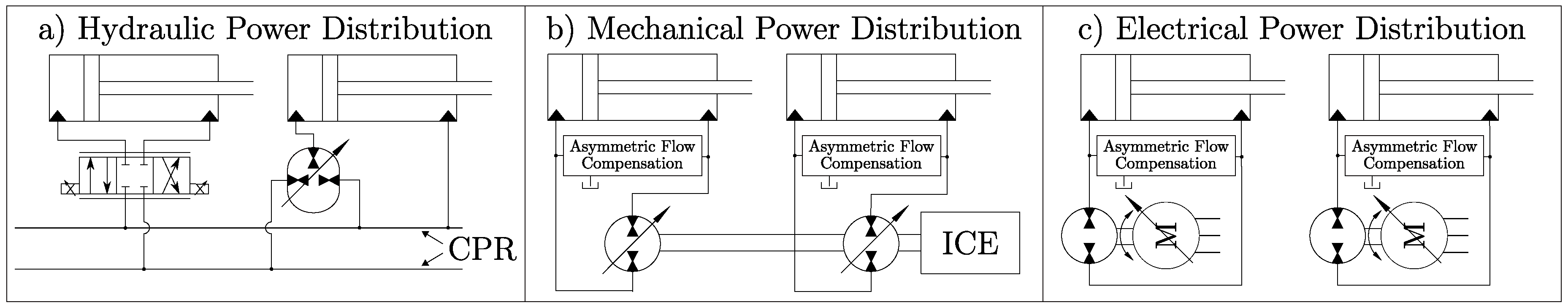
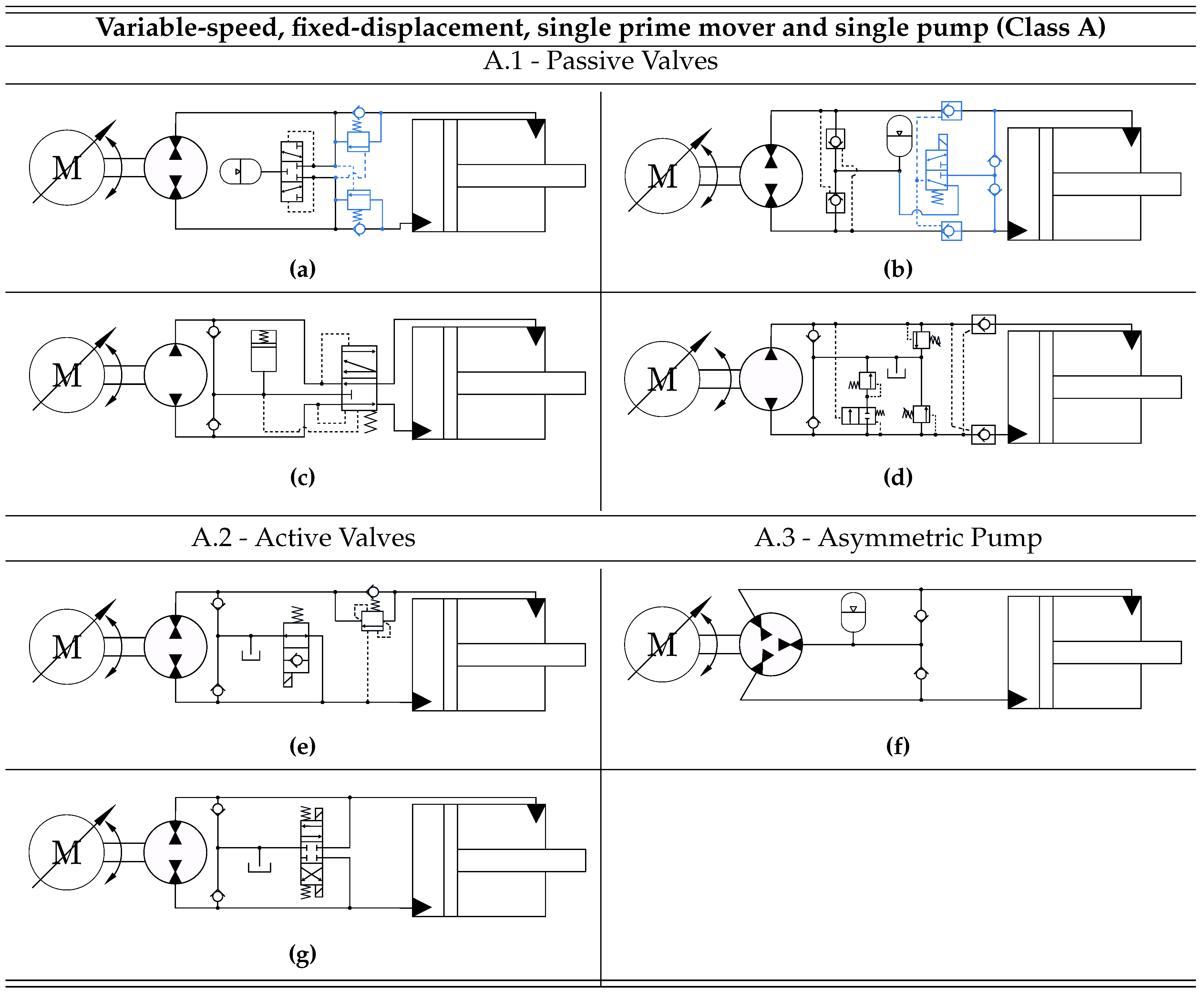
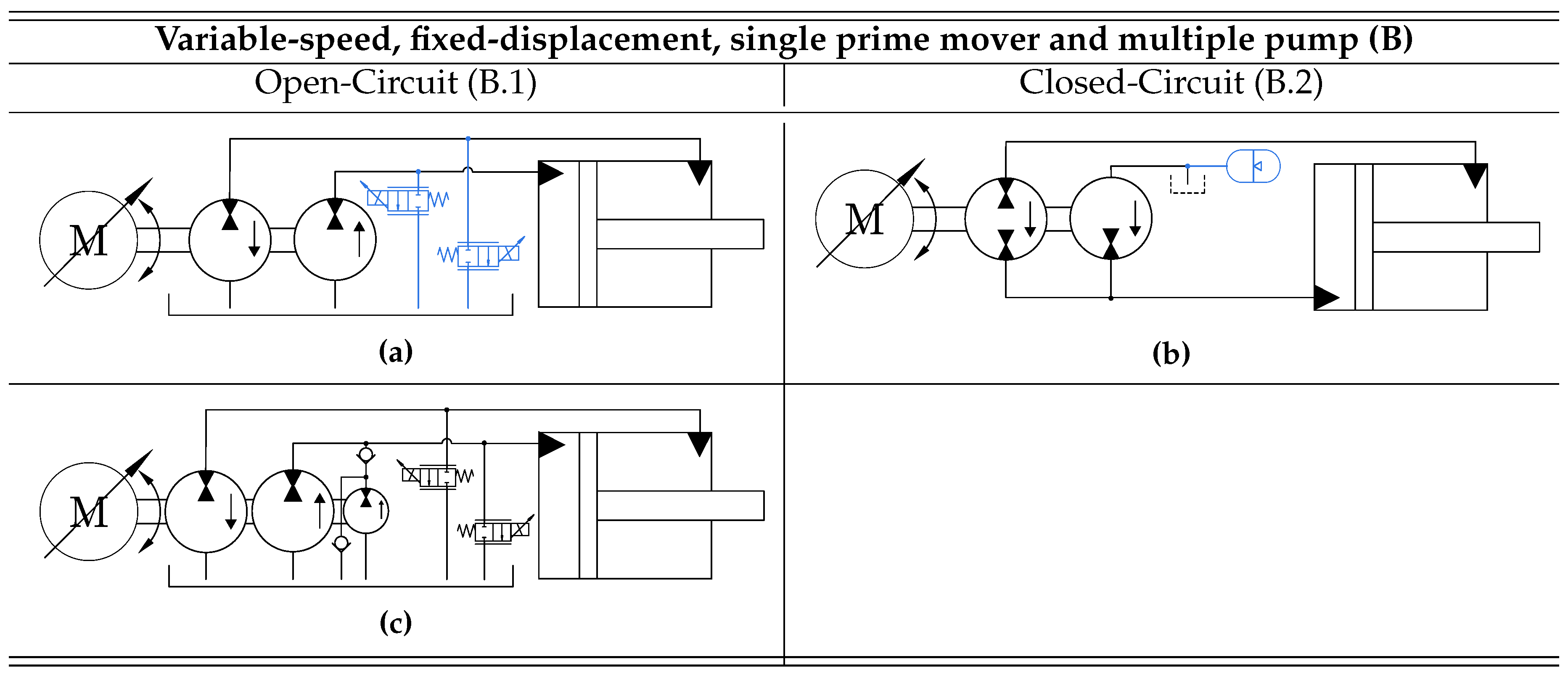
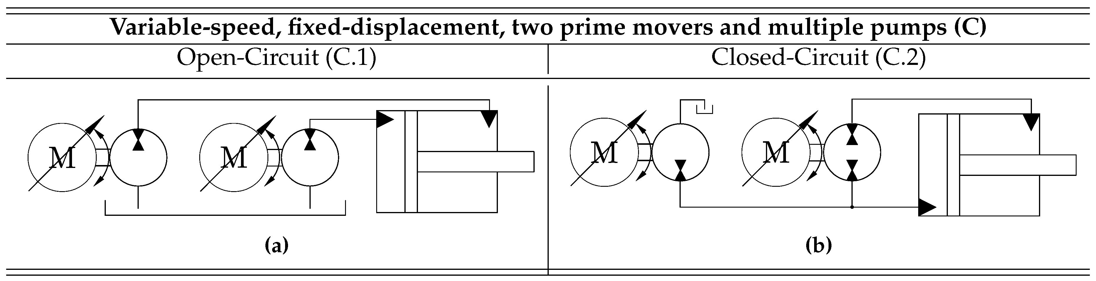
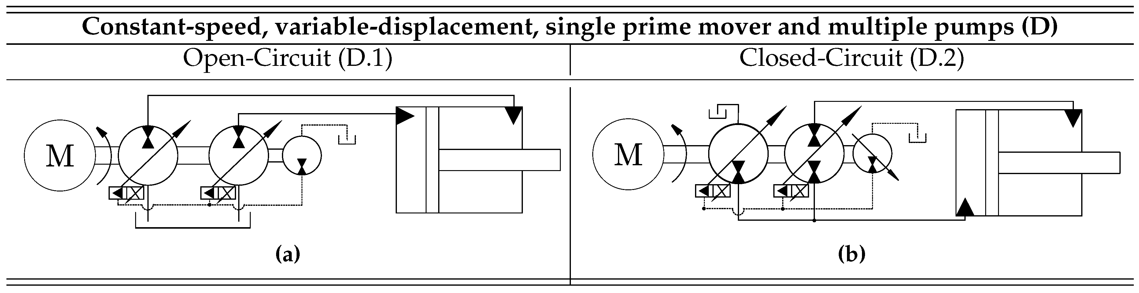
Table 1.
The derived drive classes are assessed based on eight criteria. Four different grades are used, ranging from (- -) to (+ +), with (- -) being the worst.
Table 1.
The derived drive classes are assessed based on eight criteria. Four different grades are used, ranging from (- -) to (+ +), with (- -) being the worst.
| Comparison between the Proposed Drive Classes | |||||
|---|---|---|---|---|---|
| Class A | Class B | Class C | Class D | Class E | |
| Energy efficiency | + | + | + | - | - |
| Ability to control drive stiffness | - - | - | + + | + + | + + |
| Ability to handle highly | - - | + | + + | + + | - |
| dynamic/switching loads | |||||
| Drive compactness and | + + | + + | + | - | - |
| flexibility | |||||
| Hydraulic circuit simplicity | + | + + | + + | - | - |
| Control simplicity | + | + | - | - | + |
| Reliability | - | - | - | + + | + + |
| Degree of scalability | - | - | + | + + | + + |
© 2019 by the authors. Licensee MDPI, Basel, Switzerland. This article is an open access article distributed under the terms and conditions of the Creative Commons Attribution (CC BY) license (http://creativecommons.org/licenses/by/4.0/).
Share and Cite
MDPI and ACS Style
Ketelsen, S.; Padovani, D.; Andersen, T.O.; Ebbesen, M.K.; Schmidt, L. Classification and Review of Pump-Controlled Differential Cylinder Drives. Energies 2019, 12, 1293. https://doi.org/10.3390/en12071293
AMA Style
Ketelsen S, Padovani D, Andersen TO, Ebbesen MK, Schmidt L. Classification and Review of Pump-Controlled Differential Cylinder Drives. Energies. 2019; 12(7):1293. https://doi.org/10.3390/en12071293
Chicago/Turabian StyleKetelsen, Søren, Damiano Padovani, Torben O. Andersen, Morten Kjeld Ebbesen, and Lasse Schmidt. 2019. "Classification and Review of Pump-Controlled Differential Cylinder Drives" Energies 12, no. 7: 1293. https://doi.org/10.3390/en12071293
Note that from the first issue of 2016, this journal uses article numbers instead of page numbers. See further details here.