Article

Battery Characterization and Dimensioning Approaches for Micro-Grid Systems †

by
Sofia Boulmrharj
1,2,*,
Youssef NaitMalek
1,3,
Abdellatif Elmouatamid
1,2,
Mohamed Bakhouya
1,
Radouane Ouladsine
1,
Khalid Zine-Dine
2,
Mohammed Khaidar
2 and
Mostapha Siniti
2
1
FIL-ECINE, LERMA Lab, International University of Rabat, Sala El Jadida 11100, Morocco
2
CUR”EnR&SIE”, LAROSERI Lab, Faculty of Sciences El Jadida, Chouaib Doukkali University, El Jadida 24000, Morocco
3
ENSIAS, Mohamed V University, Rabat 10713, Morocco
*
Author to whom correspondence should be addressed.
This paper is an extended version of our paper Boulmrharj, S.; NaitMalek, Y.; ElMouatamid, A.; Bakhouya, M.; Ouladsine, R.; Zine-Dine, K.; Khaidar, M.; Abid, R. Approach for Dimensioning Stand-alone Photovoltaic Systems, in Proceedings of the 5th International Conference on Energy and Environment Research (ICEER), Prague, Czech Republic, 23–27 July 2018; Volume 153, pp. 56–61.
Energies 2019, 12(7), 1305; https://doi.org/10.3390/en12071305
Submission received: 15 December 2018 / Revised: 21 February 2019 / Accepted: 22 March 2019 / Published: 4 April 2019
(This article belongs to the Special Issue Sustainable Energy Systems)

Abstract

:
Micro-Grid (MG) systems have been extensively studied and deployed to lower the power consumption while reducing the greenhouse gas emissions. Although, the challenge with Renewable Energy Sources (RES) is their uncertain and intermittent nature, things that led the researchers to think about integrating storage devices, especially batteries, into MG systems. The main aim is to store the excess of produced energy for further usage when not enough energy is available. Nevertheless, batteries modeling and characterization is mandatory to identify their parameters and study their performance within MG systems. Moreover, in order to continuously supply electricity to the building, it is required to figure out the optimum size of energy production systems and storage devices. This paper introduces a methodology for MG modeling and performance evaluation. Its main contribution is twofold, (i) battery’s parameters identification, and (ii) modeling and dimensioning method for both standalone and MG systems. An instrumentation platform, composed of recent sensing and actuating equipment, for MG energy management and battery characterization is developed. Simulation and experimental results show the effectiveness of the proposed methodology.

1. Introduction

Due to their advantages and benefits (e.g., clean, abundant), Morocco focuses its interest on RES (especially solar energy with an average daily global radiation of around 5 kWh/m2 [1]) in order to decrease its external dependence on fossil fuel products (e.g., coal, fuel, oil, natural gas), which is around 95%. For these advantages, MG systems have been broadly studied and deployed in order to decrease the power consumption from the electric grid while minimizing the greenhouse emissions. Though, because of the intermittent nature of RES, it is mandatory to store the excess of produced energy from RES (e.g., solar energy) in order to supply electricity to the building’s appliances when there is no production. On the other hand, several energy storage systems exist, such as batteries, flywheel energy storage systems, superconductors, and Pumped Hydroelectric Energy Storage (PHES) [2]. Among these storage devices, batteries are the most used component in MG systems due to their benefits (e.g., modularity, fast response and good energy efficiency). Besides, for remote and rural regions, which are not linked to the electric grid, figuring out the suitable size of energy production systems and storage devices is necessary for continuous electricity supply.
Modeling and sizing of MG systems, which are composed of RES and storage devices, have been extensively studied in recent years in order to facilitate their deployment and improve their behavior and performance [3]. Regarding the sizing of these systems, several parameters must be determined to compute the optimal size of each component, such as ambient temperature, solar irradiation and consumption profile [4,5,6]. In the literature, two methods for sizing MG systems are presented. The first one consists of sizing the system using the yearly averaged monthly values of the different parameters, while the second method is characterized by using the worst month’s parameters. For instance, authors in [7] have reviewed several approaches (e.g., deterministic, stochastic) for optimizing the sizing of MG systems in order to insure the power during all the day and to minimize the cost investment.
Concerning the modeling, several models for each component of the MG systems have been proposed and developed in order to estimate their performance under various conditions [6,8]. Regarding PV panels, researchers have developed a mathematical model of the solar cells’ electrical circuit, which takes into consideration different weather conditions (e.g., temperature, solar irradiation), in order to estimate their behavior [6]. The complicated behavior of the batteries is caused by the fact that many parameters (e.g., voltage, current, temperature) vary during the charge and the discharge cycles, which makes the estimation and the prediction of their performance and also their State of Charge (SoC) much more difficult [8]. In the literature, several battery models (e.g., electrical-circuit models, electrochemical models) [9] and battery characterization methodologies (e.g., OCV test, impedance spectroscopy, Recursive least Squares, Kalman filter) [10,11,12,13] have been developed to predict the batteries’ behavior. Concerning the electrochemical models, the complex nature of the battery’s electrochemistry and its dependency on the temperature makes the model much more complicated, rendering it more difficult to estimate the model’s parameters. On the other hand, the electrical-circuit models (e.g., the first order RC model, the second order RC model), which are composed of a voltage source, resistors and capacitors, are the most used models for simulating the battery’s behavior because of their accuracy and simplicity. There are many variants of these models that can accurately simulate the battery’s behavior, as reviewed by the authors in [14,15,16]. It’s worth noting that the most used battery characterization methodology is the Recursive least Squares (RLS) algorithm because of its simplicity compared to other methods [12]. It aims to online identify the battery’s parameters by minimizing the difference between the simulation and experimental results, in order to accurately improve the battery’s model and thus the SoC estimation. Moreover, several methods and techniques have been developed in order to monitor and estimate the battery’s SoC in real time [11,17], such as, coulomb counting, artificial neural network (ANN) and kalman filter (KF), as reviewed by Piller et al. in [18]. Coulomb counting method, called also Ah method, which is the simplest method for monitoring the battery’s SoC [19], is based on dynamic measurement of the battery’s current, but due to sensors’ noises, large SoC errors can occur. Other methods have been also proposed and developed as intelligent methods, such as, KF, ANN and Fuzzy logic, in order to estimate and predict the battery’s SoC [8,19,20,21,22]. Besides, the battery needs a management system, which is in our case a regulator that regulates the battery’s charge and discharge in order to avoid damaging the battery and the diminution of its life-time [6], for integrating it into the MG system. On the other hand, the MG system can be composed also by an AC/DC converter that can convert the alternative current received from the electric grid to the direct current in order to operate the DC loads when there is no production and the batteries are empty. Regarding these converters, called also rectifiers, which are widely used these last years in several domains (e.g., battery charging for electric vehicles), they are usually composed of diodes and thyristors [23]. However, this type of rectifiers suffers from many problems (e.g., poor power quality, low efficiency). For that, the use of filters (e.g., passive filters, active filters and hybrid filters) is necessary in order to improve the quality of the power. Nevertheless, these filters are costly and have reasonable losses, leading to decrease in system’s efficiency [23]. For all these problems, researchers have developed a new variety of rectifiers using new solid state self-commutating devices such as MOSFETs, IGBTs in order to increase their efficiency and the quality of the power while minimizing their cost [23].
Though, authors in [24,25] have reviewed some deployed MG test-beds all over the world, and have shown the importance of the deployment of these systems in real-siting in order to validate the MG components’ models used in simulations. For that, we have conducted the work presented in this article, which is a part of the work we are undertaking under an ongoing project, named MIGRID, aiming to model, simulate and experiment an MG system for sizing and control approaches [26]. The system is composed of five components, which are PV panels for producing electricity, batteries in order to supply electricity to the building when there is no production, a regulator to control the batteries’ charge and discharge, a rectifier that converts the alternating current (AC) received from the electric grid into a direct current (DC) for operating the DC loads, and the electric grid for supplying the building when there is no production and the batteries are empty. The contribution in this article is as follows: the system has been first modeled and evaluated using both simulations and experiments under the same conditions, with the aim to study its behavior and validate the developed components’ models. Nevertheless, batteries modeling and characterization is mandatory to identify their parameters and study their performance within MG systems. Therefore, an instrumentation platform, composed of recent sensing and actuating equipment, is developed for evaluating the efficiency of MG components’ models.
The remainder of this article is structured as follows. Section 2 describes the proposed methodology followed throughout the article. The description, the modeling and the simulation and experimental results of the MG system are introduced in Section 3. In Section 4, a sizing method is introduced in order to make the MG system a stand-alone system, and then simulation and experimental results are presented. Finally, the conclusions and perspectives are given in Section 5.

2. Proposed Methodology

Figure 1 describes the different steps of the proposed methodology, (i) battery modeling and characterization, (ii) MG system modeling, simulations and experiments, and (iii) Stand-alone system sizing and performance evaluation. Modeling and characterization is a mandatory step to identify battery’s parameters and study their behaviour and performance within MG systems. Therefore, an instrumentation platform, composed of recent sensing and actuating equipment, has been developed in order to collect the battery’s characteristics (e.g., current and voltage). The data collected have been fed to the Recursive Least Squares (RLS) algorithm. It is an algorithm able to identify the battery’s parameters that minimize the difference between the simulation and experimental results. These parameters have then been integrated into the used battery model presented in [15,16]. Simulations and experiments have been conducted under the same conditions in order to validate the proposed battery characterization methodology.
Concerning the MG system, each component of the system has been modeled and connected to the battery’s model. The aim is to simulate the whole system, using the same conditions as in the experimentation in order to figure out first the system’s behaviour and validate the components’ models. These validated models could be used for conducting further simulations accordingly. Regarding the third step, a sizing method has been introduced for stand-alone systems. Then, simulations have been carried out using the components’ models validated in the second step. Similarly, experimentations have been conducted and obtained results are compared to those from simulations. The results validate the introduced sizing method and show full independence from the electric grid. This methodology can be applied to other stand-alone systems.

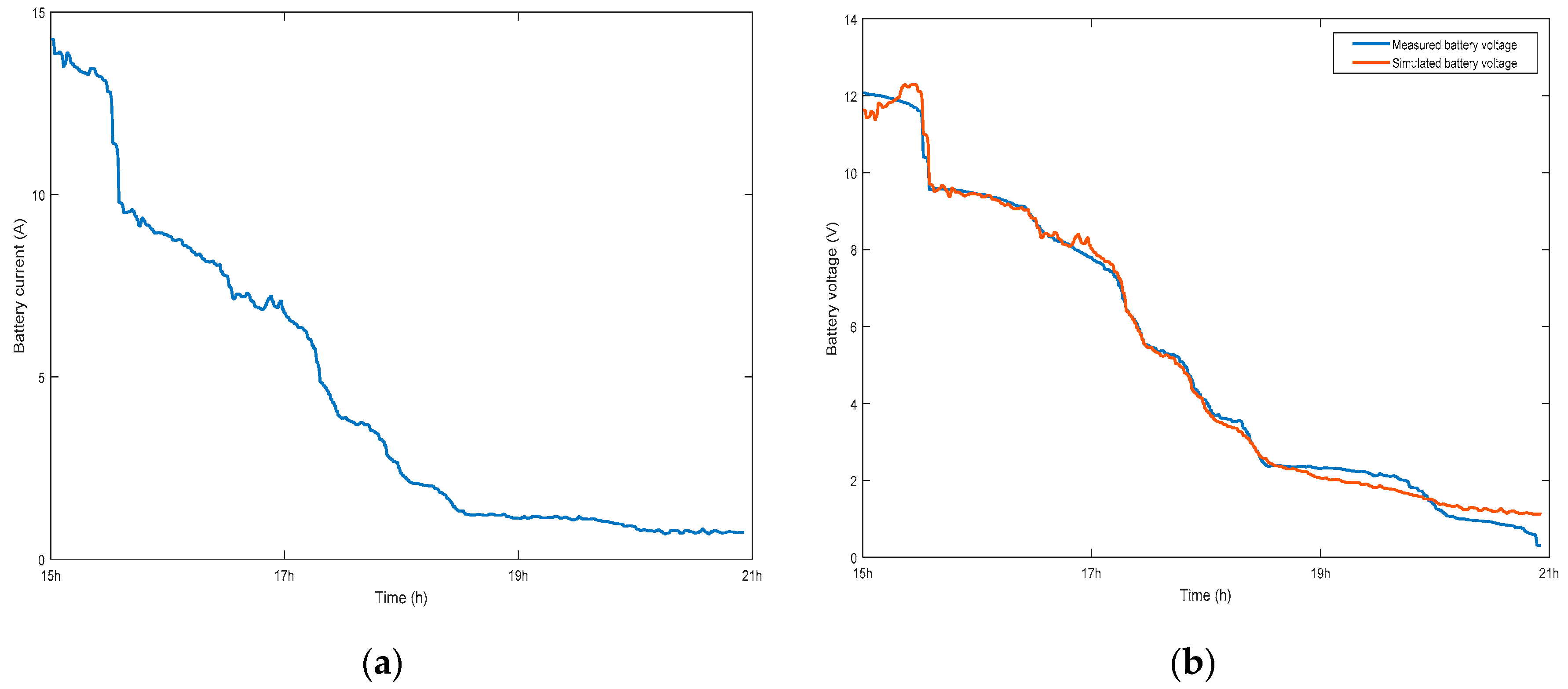
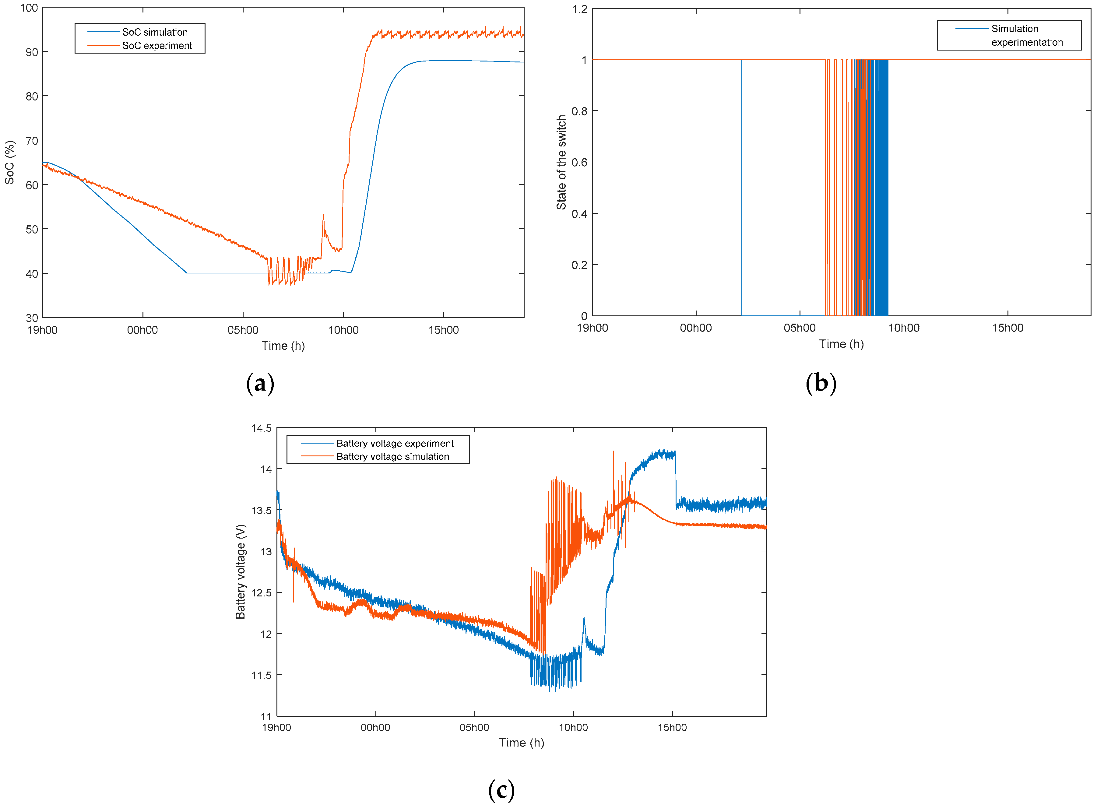
3. Simulation and Experimental Results of the MG System

Figure 2 describes the architecture of the MG system that we have deployed in our EEBLab test-bed.
The system presented above is composed of a PV module with 265 W as a peak power, a 24 Ah and 12 V Lead-acid battery fabricated by the Genesis NP24-12R, a regulator “BlueSolar MPPT 150/35”, and a 24 W and 12 V ventilation system composed of two fans operating with a PWM control. The grid is connected to the load through a rectifier with an output voltage of 12 V. Moreover, a platform [27], constituted by a set of voltage and current sensors and an actuator connected to an Arduino board, has been deployed in order to measure the voltage and the current in all branches of the MG system (see Figure 3).
The data collected from sensors are sent via a Raspberry Pi to a cluster for processing and storage. Furthermore, using this platform, the battery’s SoC, which is necessary for controlling the MG system, is also estimated using the coulomb counting method (Ah method). Besides, the actuator, which is controlled by the Arduino board, has been used in order to alter between the PV-Battery system and the electric grid when the SoC of the battery reaches 40%. Moreover, the state and the powers in each branch of the system are visualized and extracted using a web application that has been already developed. The aim of the deployment of this system is to compare the simulation and experiment results in order to validate the components’ models and behavior, especially at night when there is no PV production.
The first goal of this work is to model the MG system and conduct simulations under MATLAB/Simulink using similar experimental conditions. For this purpose, the model of each component (e.g., PV module, regulator, battery, and rectifier) of the system have been developed. In a previous work [6], we have described with more details the models of the PV module and the regulator. For the model of the AC/DC converter, four IGBTs (Insulated Gate Bipolar Transistor) have been used and controlled by a PWM (Pulse-width modulation) signal and a filter have been also used in order to improve the quality of the power.
Regarding the battery, the model presented in [15,16] was used for the purpose of estimating the battery’s behavior. This model is a variant of the model presented in [14]. It takes into consideration, in addition to the OCV (Open Circuit Voltage), which is a function of the battery’s SoC and the polarization resistance, the polarization voltage for the purpose of representing the non-linearity relationship between the OCV and the SoC. The equations of the Lead acid battery voltage (in Volt) in both charge (i < 0) (1) and discharge (i > 0) (2) modes are expressed respectively as follows [15,16]:
V b a t t = E 0 R i K Q i t 0.1 Q i * K Q Q i t i t + e x p ( t )
V b a t t = E 0 R i K Q Q i t ( i t + i * ) + e x p ( t )
where, Vbatt is the battery voltage (V), E0 is the battery constant voltage (V), K is the polarization constant (V/(Ah)) or polarization resistance (Ω), Q is the battery capacity (Ah), it is the actual battery capacity (Ah), R is the internal resistance (Ω), i is the battery current (A), i* is the filtered current (A), and exp(t) is an expression that represents the exponential zone voltage (V). The latter term represents the hysteresis phenomenon between the charge and the discharge that takes place in the exponential zone as follows [15]:
e x p ( t ) ˙ = B | i ( t ) | ( e x p ( t ) + A u ( t ) )
where i(t) is the battery current (A), u(t) represents the charge (u(t) = 1) or discharge (u(t) = 0) mode, A is the exponential zone amplitude (V), and B is the exponential zone time constant inverse (Ah)(−1).
The battery’s model has been built using these equations in Matlab/Simulink (R2017a). However, in order to use this model, the identification of the battery’s parameters (i.e., estimate the battery’s parameters of our deployed battery using the experimental data) is required. For that, as illustrated in Figure 4, an instrumentation platform was developed in order to extract the battery’s characteristics, which are the battery’s voltage and current, during the charge and the discharge modes using voltage and current sensors, which are connected to an Arduino board in order to gather the data. The gathered data are then sent to a cluster via a Raspberry Pi for processing, filtering, storage and real time visualization [27].
Therefore, several charge/discharge experiments have been carried out and the gathered data have been processed and filtered. Then, the Recursive Least Squares method (RLS) [28], which is a method that recursively comes up with the parameters that minimize the difference between the simulation and experimental results, has been applied to these data in order to identify the battery’s parameters that are presented in Table 1.
Finally, the identified parameters have been integrated into the battery’s model for validating the proposed battery characterization methodology. Simulations and experiments have been conducted under the same conditions (i.e., the same current have been applied and the computed battery’s voltage in both experimentation and simulation has been compared), and results show the accuracy of the characterization methodology [29]. For instance, Figure 5 (Resp. Figure 6) depicts the battery’s current and voltage in the charging mode (Resp. the discharging mode) from both simulations and experiments. As observed in these figures, the curves from both experiments and simulations show the same behavior, and the errors between both of them are in the vicinity of the threshold (i.e., the maximum error must be fewer than 5% [30]), which validates the accuracy of the proposed battery characterization methodology. The slight errors between the simulations and experiments may be caused by the measurement noises and the instability of the sensors, or especially by not taking into consideration in the battery’s model the temperature’s effect on its properties.
The battery’s model with the identified parameters was then integrated into our MG system (Figure 7) in order to simulate the system’s behavior and compare the simulations to the experiments.
In order to show the system’s behavior and validate the components’ models, several simulations and experiments have been carried out during a sunny day, and the results are depicted in Figure 8. For instance, Figure 8b,c show that during the daytime, the electricity needed by the ventilation system is totally supplied by the PV panel (the actuator is switched to the PV-Battery system) whereas the battery is charged by the excess energy production. Nevertheless, during the night, the electric grid operates the load, especially after 5AM when the battery’s SoC (Figure 8a), which is estimated using the Ah method, is fewer than 40%.
According to these results, the electricity produced by the PV is not sufficient to totally supply the ventilation system. Thus, a sizing method was established with the purpose of making the system fully autonomous. Then, simulations and experiments have been carried out for validating the sizing method towards a total independence from the electric grid.

4. Sizing of the Stand-Alone System

The sizing of the MG system, which is introduced in the previous section, depends on many important parameters (e.g., consumption profile, solar irradiation) [4,5,6]. Regarding the solar irradiation, the PVGIS application that provides the solar irradiation using the geographical coordinates of any site in Africa or Europe, have been used. In order to provide the average monthly solar radiation all over the year, geographical coordinates of our site (Latitude 34°00′47″ N, Longitude 6°49′57″ W, Altitude 46 m) were inputted. Concerning the consumption, a set of voltage and current sensors have been deployed in order to monitor the ventilation system’s daily electricity consumption (see Figure 9), which is around 430 Wh.
Then, the peak power of the PV panels (in W) is computed using the following expression [5,6]:
P c = E e l e c × I r 0 E i × P R
where Eelec is the maximal daily electricity consumption (kWh/day), I r 0 is the irradiance at standard conditions STC (equal to 1000 W/m2), Ei is the lowermost average monthly solar irradiation all over the year (kWh/m2/day); for our site, it is equal to 4790 kWh/m2/day that corresponds to the December’s irradiation, PR (Performance Ratio) that depends on many parameters, such as battery’s efficiency, converter’s efficiency, voltage drop in the cables, other losses in the installation, the integration mode, is a correction coefficient for stand-alone systems, which is between 0.55 and 0.75 [31]. The value used in our case is equal 0.70.
In order to meet the needed electricity demand, the required PV panels’ peak power is 128.243 Wc. As mentioned above, the peak power of the PV module used in this experiment is 265 W, its open circuit voltage is 38.3 V and 8.98 A is the short-circuit current. As a result, one module is required in order to operate the system all over the year, which is computed using the following equation: Nt = P c P m o d u l e , with a total peak power of 265 W and a total area of 1.63 m2. Concerning the regulator, the same one as in the previous experiment have been used because the PV module has not changed. Furthermore, the battery’s capacity (CAh), which is in Ah, is expressed by the following equation [5]:
C Ah = E e l e c × N A u t D o D × η B × V b a t
where Eelec is the maximal daily electricity consumption (Wh/day), NAut is the number of days of autonomy (day), DoD is the Depth of Discharge (%), ηB is the battery’s efficiency (%), and Vbat is the battery’s voltage (V). The estimation of the battery’s capacity requires the knowledge of the number of days of autonomy, which differs from site to another according to weather conditions. The objective is to supply the electricity to the building from batteries when there is no production. In our case, the number of days of autonomy fluctuates between one and three days. In our computations, the value used is one day. A battery of 12 V with a DoD equal to 60% and a battery’s efficiency of 85% has been chosen. 70.26 Ah was found to be the required capacity to install. As a result, we have chosen to work with one battery of 12 V and 75 Ah manufactured by “Electra”. Besides, the electric grid is connected to the system through a rectifier that provides 12 V as output voltage with the current needed by the ventilation system.
In order to prove the accuracy of the sizing method, several experiments and simulations have been carried out. However, for simulating the whole system, the characterization of the battery is required. After identifying the battery’s parameters that are shown in Table 2, the battery’s model has been connected to the other components’ models and several simulations and experiments have been carried out.
The simulation and experimental results illustrated in Figure 10 demonstrate that during the night, the electricity needed by the ventilation system is supplied totally by the battery and there is no switching to the electric grid. These results prove the accuracy of the sizing method and also the efficiency of the used battery’s model and the characterization methodology.

5. Conclusions and Perspectives

In this work, a MG system has first been deployed in our EEBLab, and experimental results revealed the power control’s behavior, which allows switching between the PV-battery system and the electric grid. Also, these results demonstrate that the electricity needed to operate the ventilation system is not totally produced by the deployed MG system. For that, a sizing method based on the consumption profile of the ventilation system and the weather conditions of our site, has been introduced in order to upgrade the MG system for the aim to produce the total electricity needed by the load. The results prove the accuracy of this method for sizing this type of systems. Besides, in order to simulate the MG system for the aim to compare the simulation to the experiment, a model of each component of the system is needed. For that, all the components of the system have been modeled. In this work, studying the behavior of the batteries within the MG system was our main focus. Therefore, their characterization must be determined in order to model them properly. As a result, a platform composed of sensing/actuating equipment was firstly developed and deployed in order to gather several battery’s characteristics (e.g., voltage, current) that were used to build the battery’s model. Simulations of the MG system have been conducted under the same experimental conditions, and the results compared to the experimental ones showed similar behavior. Furthermore, the obtained results showed the accuracy of the battery characterization methodology. Therefore, our ongoing work concentrates on the improvement of the battery’s model by taking into consideration the influence of the temperature on the battery’s properties. Also, we focus on the battery’s SoC forecasting, which is necessary for establishing predictive control approaches in order to manage in real-time our MG system [32].

Author Contributions

Conceptualization, S.B., M.B. and R.O.; Data curation, Y.N.; Methodology, S.B. and M.B.; Software, S.B., Y.N., A.E. and R.O.; Supervision, M.B., K.Z.-D. and M.K.; Validation, M.B., M.K. and M.S.; Writing—Original Draft, S.B.; Writing—Review & Editing, S.B., M.B., K.Z.-D. and M.K.

Funding

This research was funded by USAID under the PEER program, grant number 5-398.

Acknowledgments

This work is supported by MIGRID project (grant 5-398, 2017–2019), which is funded by USAID under the PEER program.

Conflicts of Interest

The authors declare no conflict of interest.

References

  1. Othieno, H.; Awange, J. Energy Resources in Africa, Distribution, Opportunities and Challenges; Springer: New York, NY, USA, 2016. [Google Scholar]
  2. Bajracharya, Q. Dynamic Modeling, Monitoring and Control of Energy Storage System. Master’s Thesis, Karlstad University, Karlstad, Sweden, 2013. [Google Scholar]
  3. Denherder, T. Design and Simulation of Photovoltaic Super System Using Simulink. Ph.D. Thesis, California Polytechnic State University, San Luis Obispo, CA, USA, 2006. [Google Scholar]
  4. Berouine, A.; Lachhab, F.; Nait Malek, Y.; Bakhouya, M.; Ouladsine, R. A Smart Metering Platform using Big Data and IoT Technologies. In Proceedings of the CloudTech, Rabat, Morocco, 24–26 October 2017; pp. 1–6. [Google Scholar] [CrossRef]
  5. Djafour, A.; Aida, M.S.; Azoui, B. Photovoltaic assisted fuel cell power systems. Energy Procedia 2014, 50, 306–313. [Google Scholar] [CrossRef]
  6. Boulmrharj, S.; Rabeh, R.; Felix, V.; Ouladsine, R.; Bakhouya, M.; Zine-dine, K.; Khaidar, M.; Siniti, M.; Abid, R. Modeling and dimensioning of grid-connected photovoltaic systems. In Proceedings of the IRSEC’17, Tangier, Morocco, 4–7 December 2017. [Google Scholar] [CrossRef]
  7. Anoune, K.; Bouya, M.; Astito, A.; Ben Abdellah, A. Sizing methods and optimization techniques for PV-wind based hybrid renewable energy system: A review. Renew. Sustain. Energy Rev. 2018, 93, 652–673. [Google Scholar] [CrossRef]
  8. Seaman, A.; Dao, T.; McPhee, J. A survey of mathematics-based equivalent-circuit and electrochemical battery models for hybrid and electric vehicle simulation. Power Sources 2014, 256, 410–423. [Google Scholar] [CrossRef]
  9. Sun, K.; Shu, Q. Overview of the types of battery models. In Proceedings of the Chinese Control Conference, Yantai, China, 22–24 July 2011; pp. 3644–3648. [Google Scholar]
  10. Zhang, C.; Allafi, W.; Dinh, Q.; Ascencio, P.; Marco, J. Online Estimation of Battery Equivalent Circuit Model Parameters and State of Charge using Decoupled Least Squares Technique. Energy 2017. [Google Scholar] [CrossRef]
  11. Ramadan, H.S.; Becherif, M.; Claude, F. Extended kalman filter for accurate state of charge estimation of lithium-based batteries: A comparative analysis. Int. J. Hydrog. Energy 2017, 29033–29046. [Google Scholar] [CrossRef]
  12. Xia, B.; Lao, Z.; Zhang, R.; Tian, Y.; Chen, G.; Sun, Z.; Wang, W.; Sun, W.; Lai, Y.; Wang, M.; et al. Online Parameter Identification and State of Charge Estimation of Lithium-Ion Batteries Based on Forgetting Factor Recursive Least Squares and Nonlinear Kalman Filter. Energies 2018, 11, 3. [Google Scholar] [CrossRef]
  13. Mauracher, P.; Karden, E. Dynamic Modelling of Lead-acid Batteries using impedance spectroscopy for Parameter Identification. Power Sources 1997, 67, 69–84. [Google Scholar] [CrossRef]
  14. Shepherd, C.M. Design of Primary and Secondary Ceils: II. An Equation Describing Battery Discharge. J. Electochem. Soc. 1965, 112, 657–664. [Google Scholar] [CrossRef]
  15. Tremblay, O.; Dessaint, L.-A. Experimental Validation of a Battery Dynamic Model for EV Applications. World Electr. Veh. J. 2009, 3, 289–298. [Google Scholar] [CrossRef]
  16. Tremblay, O.; Dessaint, L.-A.; Dekkiche, A. A Generic Battery Model for the Dynamic Simulation of Hybrid Electric Vehicles. In Proceedings of the VPPC, Arlington, TX, USA, 9–12 September 2007; pp. 284–289. [Google Scholar] [CrossRef]
  17. Barillas, J.K.; Li, J.; Günther, C.; Danzer, M.A. A comparative study and validation of state estimation algorithms for Li-ion batteries in battery management systems. Appl. Energy 2015, 155, 455–462. [Google Scholar] [CrossRef]
  18. Piller, S.; Perrin, M.; Jossen, A. Methods for state-of-charge determination and their applications. Power Sources 2001, 96, 113–120. [Google Scholar] [CrossRef]
  19. Windarko, N.A.; Choi, J.; Chung, G. SOC estimation of LiPB batteries using Extended Kalman Filter based on high accuracy electrical mode. In Proceedings of the ICPE, Jeju, Korea, 30 May–3 June 2011. [Google Scholar]
  20. Vasebi, A.; Partovibakhsh, M.; Taghi Bathaee, S.M. A novel combined battery model for state-of-charge estimation in lead-acid batteries based on extended Kalman filter for hybrid electric vehicle applications. Power Sources 2007, 174, 30–40. [Google Scholar] [CrossRef]
  21. Vasebi, A.; Partovibakhsh, M.; Taghi Bathaee, S.M. Predicting state of charge of lead-acid batteries for hybrid electric vehicles by extended kalman filter. Energy Convers. Manag. 2008, 49, 75–82. [Google Scholar] [CrossRef]
  22. Ting, T.O.; Man, K.L.; Lei, C.; Lu, C. State-of-charge for battery management system via Kalman filter. Eng. Lett. 2014, 22, 75–82. [Google Scholar]
  23. Singh, B.; Singh, B.N.; Chandra, A.; Al-Haddad, K.; Pandey, A.; Kothari, D.P. A Review of Single-Phase Improved Power Quality AC–DC Converters. IEEE Trans. Ind. Electron. 2003, 50. [Google Scholar] [CrossRef]
  24. Lidula, N.W.A.; Rajapakse, A.D. Microgrids research: A review of experimental microgrids and test systems. Renew. Sustain. Energy Rev. 2011, 15, 186–202. [Google Scholar] [CrossRef]
  25. Nayar, C.; Tang, M.; Suponthana, W. Wind/PV/Diesel Micro Grid System implemented in Remote Islands in the Republic of Maldives. In Proceedings of the ICSET, Singapore, 24–27 November 2008; pp. 1076–1080. [Google Scholar] [CrossRef]
  26. Bakhouya, M.; NaitMalek, Y.; Elmouatamid, A.; Lachhab, F.; Berouine, A.; Boulmrharj, S.; Ouladsine, R.; Felix, V.; Zine-dine, K.; Khaidar, M.; et al. Towards a Data-Driven Platform using IoT and Big Data Technologies for Energy Efficient Buildings. In Proceedings of the CloudTech, Rabat, Morocco, 24–26 October 2017; pp. 1–5. [Google Scholar] [CrossRef]
  27. Nait Malek, Y.; Kharbouch, A.; El Khoukhi, H.; Bakhouya, M.; Deflorio, V.; Elouadghiri, D.; Latre, S.; Blondia, C. On the use of IoT and Big Data Technologies for Real-time Monitoring and Data Processing. Procedia Comput. Sci. 2017, 113, 429–434. [Google Scholar] [CrossRef]
  28. Zeng, Z.; Tian, J.; Li, D.; Tian, Y. An Online State of Charge Estimation Algorithm for Lithium-Ion Batteries Using an Improved Adaptive Cubature Kalman Filter. Energies 2018, 11, 59. [Google Scholar] [CrossRef]
  29. Boulmrharj, S.; NaitMalek, Y.; El Mouatamid, A.; Ouladsine, R.; Bakhouya, M.; Ouldmoussa, M.; Zine-dine, K.; Khaidar, M.; Abid, R. Towards a Battery Characterization Methodology for Performance Evaluation of Micro-Grid Systems. In Proceedings of the SEST, Sevilla, Spain, 10–12 September 2018. [Google Scholar] [CrossRef]
  30. Stroe, D.-I.; Swierczynski, M.; Stroe, A.-I.; Knudsen Kær, S. Generalized Characterization Methodology for Performance Modelling of Lithium-Ion Batteries. Batteries 2016, 2, 37. [Google Scholar] [CrossRef]
  31. GuidEnR PHOTOVOLTAIQUE. Available online: http://www.photovoltaique.guidenr.fr/cours-photovoltaique-autonome-1/application-formule-calcul-puissance-crete-photovoltaique.php (accessed on 20 April 2016).
  32. Elmouatamid, A.; Nait Malek, Y.; Ouladsine, R.; Bakhouya, M.; Elkamoun, N.; Zine-Dine, K.; Khaidar, M.; Abid, R. Towards a Demand/Response Control Approach for Micro-grid Systems. In Proceedings of the ‘CoDIT’2018, Thessaloniki, Greece, 10–13 April 2018. [Google Scholar] [CrossRef]
Figure 1. Steps of the proposed methodology.
Energies 12 01305 g001
Figure 2. (a) Block diagram of the MG system; (b) the deployed prototype in our EEBLab test-bed.
Energies 12 01305 g002
Figure 3. Deployed platform for sensing and actuating.
Energies 12 01305 g003
Figure 4. Battery characterization test-bed.
Energies 12 01305 g004
Figure 5. (a) The battery’s current in the charging mode; (b) The simulation and experimental battery’s voltage in the charging mode.
Energies 12 01305 g005
Figure 6. (a) The battery’s current in the discharging mode; (b) The simulation and experimental battery’s voltage in the discharging mode.
Energies 12 01305 g006
Figure 7. The MG Simulink model used for simulations.
Energies 12 01305 g007
Figure 8. (a) The battery’s SoC; (b) The state of the relay (0: electric grid, 1: PV-Battery system); (c) The simulation and experimental battery’s voltage.
Energies 12 01305 g008
Figure 9. Ventilation system’s daily electricity consumption.
Energies 12 01305 g009
Figure 10. (a) The battery’s SoC and the state of the actuator from simulation and experiment; (b) The battery’s SoC and the PV power; (c) The simulation and experimental battery’s voltage.
Energies 12 01305 g010
Table 1. Battery’s parameters.
ParametersE0 (V)R (Ω)K (Ω or V/Ah)A (V)B (Ah−1)
Values13.320.543060.05311.557 × 10−51.7233
Table 2. Identified battery’s parameters.
ParametersE0 (V)R (Ω)K (Ω or V/Ah)A (V)B (Ah−1)
Values13.640.5140.04656.94 × 10−51.31

