A Survey on Optimization Techniques Applied to Magnetic Field Mitigation in Power Systems


1
Escuela Politécnica Superior, Universidad de Sevilla, c/ Virgen de África 9, 41011 Sevilla, Spain
2
Escuela Técnica Superior de Ingeniería, Universidad de Sevilla, Avd. de los Descubrimientos s/n, 41092 Sevilla, Spain
*
Author to whom correspondence should be addressed.
Energies 2019, 12(7), 1332; https://doi.org/10.3390/en12071332
Submission received: 28 February 2019
/
Revised: 25 March 2019
/
Accepted: 1 April 2019
/
Published: 8 April 2019
(This article belongs to the Special Issue Optimization Methods Applied to Power Systems)
Abstract
:With the continuous increase in the number and relevance of electric transmission lines and distribution networks, there is a higher exposure to the magnetic fields generated by them, leading to more cases of human electrosensitivity, which greatly necessitates the design and development of magnetic field mitigation procedures and, at the same time, the need to minimize both performance degradation and deterioration in the efficiency as well. During the last four decades, fruitful results have been reported about extremely low frequency magnetic field mitigation, giving a wide variety of solutions. This survey paper aims to give a comprehensive overview of cost-effective optimization techniques destined to magnetic field mitigation in power systems, with particular attention to the results reported in the last decade.
1. Introduction
As is known, many electrical installations, mainly overhead transmission lines (OHL), underground power cables (UPC), medium voltage/low voltage (MV/LV) substations, and building’s electrical distribution systems, are the source of extremely low frequency (ELF) (50/60Hz) magnetic fields (MF). This has led to an ever-increasing demand on the safety of people exposed to the potentially adverse health effects of MF [1]. On the electromagnetic compatibility side, the interferences coming from ELF MFs may affect the performance of electrical and electronic devices (problems in medical electric equipment due to their sensitivity [2], electromagnetic interferences caused by transmission and distribution lines on communication cables [3], etc.).
The exposure to ELF MFs may increase the overall risk of many diseases [4,5] for MF intensity values higher than certain threshold levels, capable of inducing harmful currents in the human tissues [6]. However, after more than 40 years of research, the scientific community has not yet reached an agreement on whether long exposure to MF, at levels lower than those of the international recommendations, can have an effect on human health. In this sense, international bodies, like the Council of the European Union, and international agents of experts as the International Commission on Non-Ionizing Radiation Protection (ICNIRP) [7] as well as the Institute of Electrical and Electronics Engineers (IEEE) [8], have proposed some MF reference levels. Specifically, ICNIRP establishes limits of MF exposure at 50 Hz, according to the following two typical scenarios: A total of 200 µT for general public and 1000 µT for occupational exposure [7]. These limits are based only on short-term effects on human health after exposure to considerably higher MF values, incorporating safety margins to provide adequate protection for acute effects when they are kept. In any case, no convincing evidence about chronic effects associated with acute effects for exposures below the established threshold for has yet been found. Even more, there is no clear understanding if and how ELF MFs, at the low levels emitted by common appliances, might affect human health. Thus, until this moment, any possible cause–effect relationship between the exposure to ELF MFs and derived human diseases remains unknown. Only a few studies suggest that exposures in the order of 0.4 µT may be related to childhood leukemia, although recent studies found no material association between ELF MF and this disease [9]. Due to this fact, in 2002, the International Agency for Research on Cancer (IARC), which is part of the World Health Organization (WHO), just classified ELF MFs among the “possibly carcinogenic” physical agents (Group 2B) [1], so a precautionary principle (PP) is recommended [5,9], especially in sensitive places such as hospitals, schools, and playgrounds [10]. Thus, this uncertain panorama has led some countries or local authorities to set up, frequently, much lower exposure limits than the reference levels of ICNIRP and IEEE [11], as reported in Table 1. For example, some US states, such as Florida and New York, have settled MF limits at 15 µT, for up to 230 kV, and 20 µT in higher voltages [12]. Additionally, more stringent limits have been imposed in some European countries, including Italy (where the maximum limits are 3 or 10 µT for new and existing facilities, respectively), Slovenia and Flanders (with a maximum of 10 µT), or Switzerland (with the strongest limit of 1 µT [12]).
This survey paper aims to give a comprehensive overview of optimization techniques applied to the design of ELF MF mitigation solutions in power systems, with particular attention given to the results reported in the last decade. All this work is summarized in Table 2, categorized in terms of years and methods/applications.
The rest of the paper is organized as follows. Following the introduction section, the principles of MF mitigation in electrical appliances are first presented in Section 2, highlighting the most commonly used solutions and the need for optimization tools in their design. Section 3 and Section 4 present a detailed survey on the optimization algorithms related to both intrinsic and extrinsic methods more often used in the last decades, emphasizing the main advances in this field as a result of their use. This paper ends with final remarks in Section 5.
2. Mitigation of Low-Frequency Magnetic Fields
Generally, ELF MF mitigation methods can be categorized into two different groups, that may be applied to both OHL and UPC, as well as in MV/LV substations [13]. These are intrinsic techniques and extrinsic techniques.
2.1. Intrinsic Techniques
In the first kind of techniques, the geometrical and electrical parameters of the MF source, are modified for lowering the global MF (or magnetic flux density). The most extended solutions in this category are the following [13]:
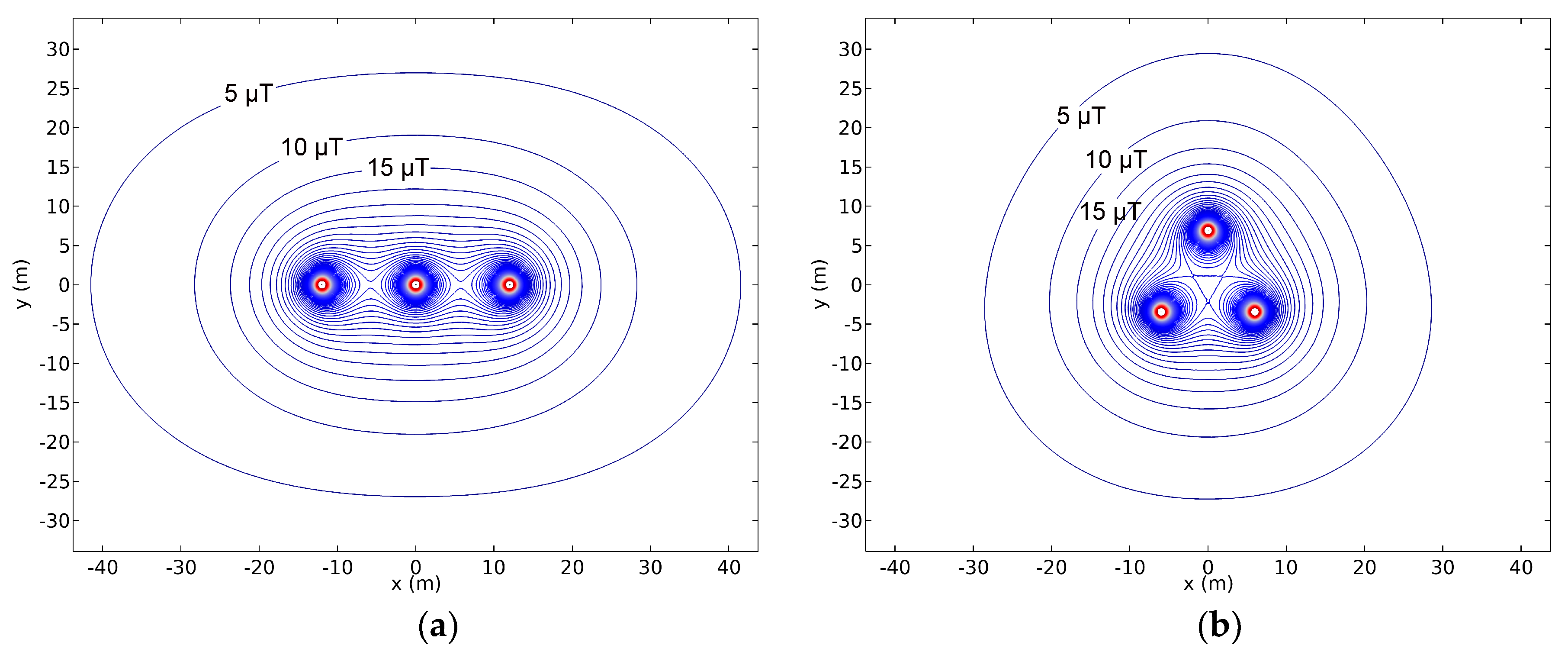
- Layout and compaction [13]: It is well-know that, when the relative positions of the conductors are rearranged (layout), for example from linear to equilateral triangle disposition, the MF decays faster as the distance to conductors increases (Figure 1). A further MF reduction can be obtained by reducing the phase-to-phase clearance (compaction). For example, by installing compactors along overhead line spans (realized through rod insulators forming equilateral triangles), a 56% reduction of the maximum ground-level MF is achievable, in comparison to an overhead transmission line realized with compacted towers (the solution that, at present, minimizes the magnetic field without compactors) [14]. However, this solution also entails a new problem, which includes higher voltage gradients on conductors and insulators, resulting in higher audible noise, radio interference, and increased hardware corona [15,16,17,18]. Additionally, the mitigation achieved can be limited, especially in UPC, where the current rating (ampacity) may be affected by these techniques [19].
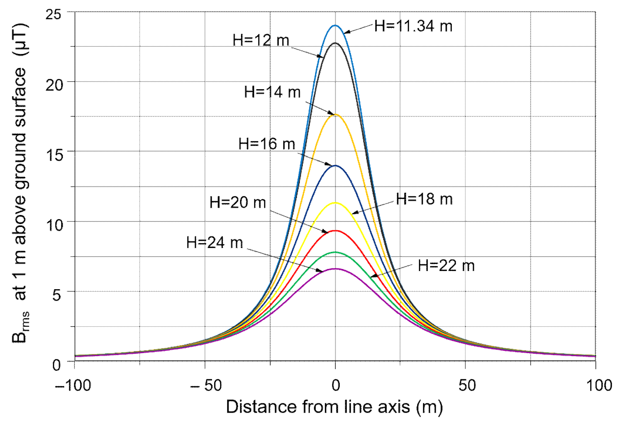
- Distance management [13]: Since the intensity of a MF decreases naturally, as a function of distance from the source, it is possible to achieve the appropriate reduced level of MF by simply increasing this distance of separation from the sources (Figure 2). This solution is limited by technical constraints (maximum height for OHL or maximum possible depth for UPC, for example).
- Phase cancellation [22]: Unlike in the phase splitting method, in the phase cancellation method the phases are just rearranged accordingly into an existing configuration. As no new material has to be added, this method is cost effective. This technique is only interesting in the case of more than one circuit. Thus, a representative phase cancellation solution is the low reactance configuration in a double circuit line (Figure 4). The greatest effectiveness of this method is limited almost exclusively to super-bundle double circuit vertical configurations, where the higher and lower phases are interchanged in the second circuit.
In addition to these solutions, and particularly for the case of UPC, a proper electrical connection of the metallic sheaths may also provide a significant reduction in the MF. In this sense, solid bonding may achieve great levels of mitigation, but with an important impact on the ampacity of the UPC.
At this point, it should be noted that the mitigation levels achieved by most of the previous techniques are usually limited and may not always meet the MF mitigation requirements for a specific location. In these situations, extrinsic techniques provide a good alternative since they are able to provide a much higher mitigation effect when needed.
2.2. Extrinsic Techniques
These techniques are based on placing additional apparatuses (mitigation system) close to the source of ELF MF or the region to be protected and can be classified as passive and active techniques [13], depending on the mechanism used to provide the mitigation effect:
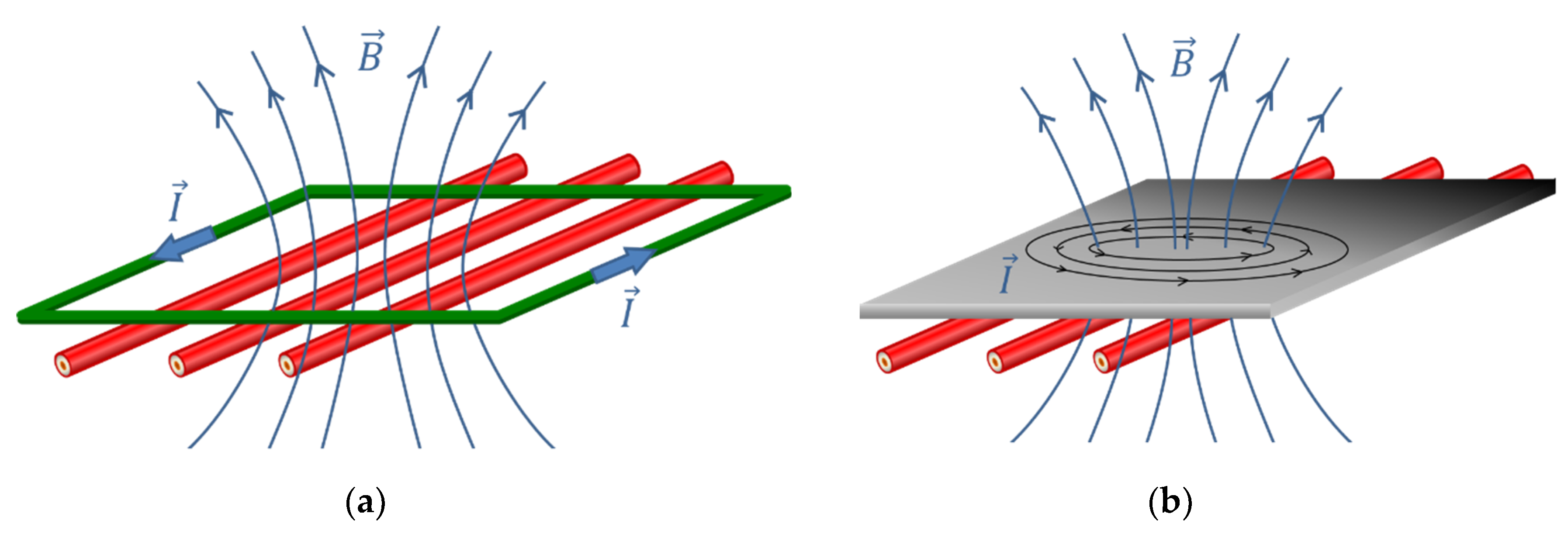
- Passive techniques [23,24,25]: In this case, the MF mitigation is obtained because the mitigation system acts in response to the MF generated by the source. For example, a typical situation is when currents are induced in these elements due to Faraday’s Law, which, in turn, generate a new MF that partially cancels the one from the source. Typical mitigation solutions in this group are passive loops [23,24] (Figure 5a) and conductive shields [25] (Figure 5b). Another case is when ferromagnetic materials are used in the mitigation system, since they have the property to attract and trap the MF flux lines thanks to their high permeability. This way, the MF flux lines are moved away from the region to be protected, resulting in a MF mitigation in that area. A good example is the use of ferromagnetic shields [25] (Figure 5c).
- Active techniques [26]: In contrast to previous solutions, active techniques require the use of external power sources to inject appropriate currents (magnitude and phase) in the mitigation system to provide the required mitigation effect (Figure 5d), and, as such, are able to provide a much higher mitigation reduction [26,27,28,29,30]. This is usually used in the so-called active loops. Nonetheless, this requires a more complex mitigation system, as it is necessary to install expensive equipment apart from MF sensors, such as the power sources, and a monitoring system to continuously adjust the injected current to achieve the required mitigation at any time [26,27,30]. All this makes this solution much more expensive than passive ones.
It should be remarked that combinations of different techniques are usually used to reduce ELF MF below a certain threshold when required. In any case, there are multiple parameters in any of the mentioned solutions that need to be adequately defined to achieve the mitigation requirements, for example, distances and clearances to the MF source, dimensions of the mitigation system and the positions of its elements, and electrical parameters or magnitude and phase for the currents to be injected. There are also a number of technical and operational constrains that must be included in the design procedure to go beyond MF minimization and incorporate other important features, such as thermal aspects, forbidden regions where the mitigation system cannot be installed, induced voltages in nearby infrastructures, failure risks, mitigation system costs, etc. In this sense, it is important to include the thermal problem in the mitigation system design procedure, since it may affect the ampacity of the mitigated system [19], especially in UPC. In this situation, the two following techniques are the most extended ones: The international standard analytical approach (IEC 60287) [31,32] and the 2-D finite-element analysis approach (FEM) [33,34]. The first line of thought is the most frequently used reference by engineers for cable sizing. In this line, considerable research efforts have been expended in modifying and enhancing its modelling capabilities under both steady-state and variable loading conditions [35,36,37]. Thus, this traditional method can be used for the thermal analysis of most of the intrinsic and extrinsic mitigation techniques, when applied to UPC. However, it is not suitable when dealing with conductive or ferromagnetic shields. The complexity of the geometry and the material properties requires a more powerful tool, like FEM [34,38,39]. With this procedure it is possible to calculate the steady-state temperatures at various points of the cable system when the mitigation system is installed and, hence, the overall cable ampacity corresponding to a specified maximum conductor temperature can be determined too [19].
All this clearly shows the need for optimization tools to obtain effective designs for the mitigation system. In the following sections a detailed survey regarding the optimization algorithms frequently used in ELF MF mitigation system design is developed.
3. Optimization Applied to Intrinsic Techniques
An optimal MF mitigation design is characterized by the MF sources and the position of the regions to be shielded. Usually, combinations of different strategies may be used to reduce the MF in an affected area. Thus, once the sources and the mitigation strategies are defined, the resulting MF can be assessed by analytical methods, usually by means of the Biot–Savart law [13,40,41]. This way, the MF mitigation performance provided by the intrinsic techniques presented earlier can be easily evaluated and optimized. In this sense, each mitigation technique has its own set of parameters that have to be optimized for minimizing the MF at the area of interest. The way in which some studies have tackled this problem for OHL and UPC, as well as in MV/LV substations, is presented next, where optimization algorithms, such as particle swarm optimization (PSO), genetic algorithms (GA), and evolutionary multi-objective optimization (EMO), are the most extended ones.
3.1. Conductor Arrangement
As mentioned previously, conductor management turns out to be a very effective way for reducing ELF MFs. Various options within this strategy can be used to reduce the field of the source by playing on the geometry of the conductors that produce such a field, e.g., three phase conductor rearrangements and phase currents split into several conductors. In the following, the main optimization techniques applied to OHL and UPC and MV/LV substations are summarized.
3.1.1. Overhead Transmission Lines
Optimal arrangement of double-circuit OHL conductors for the minimization of the ELF MF strengths constitutes a specific issue that has been the subject of numerous studies. The influence of rearranging the double-circuit overhead phase succession on ELF MF emissions was evaluated in [42,43]. In [44], it was concluded that the optimum arrangement can be easily applied to already constructed high voltage transmission lines by properly interchanging the phase conductors at the substations. A comparative studio of the ELF MF distribution in conventional and compact power line configurations is analyzed in [45,46,47].
The GA is a useful tool for determining optimal arrangements of parallel independent OHL, aimed to decrease both electric and MF emissions. In [15,48], the Monte Carlo approach implemented in GA allows for the consideration of uncertain phase shifts between independent OHL. In [49], a method for an accuracy calculation of MF under OHL is achieved by considering optimal phasing transposition for double circuit transmission lines, adding the losses in ground wire(s) and the associates side effects.
Often, optimization methods aimed to minimize ELF MF strengths join different ELF MF objective functions into a single fitness function. Typical optimization techniques are generally applied, including GA-based techniques [50], differential evolution stochastic search algorithms [44], and PSO [51]. The single fitness function for all of these optimization techniques is obtained by weighting both electric field strength and MF strength with a certain utility function. The choice of the weight or utility function is a crucial key for optimizing phase arrangements of double-circuit OHL. Moreover, the different parameters of the selected weight or utility function for minimizing the MF strengths yield different optimal solutions [52] that may involve certain side effects, as follows: Surface gradient (surface electric field) of the conductors, audible noise, apparent power losses, radio interferences, corona losses, phase inductance, phase inductance and capacitance, etc.
Developing this idea still further, the issue of the optimum phase arrangements for double-circuit OHL can be seen as a multiple-objective problem. The multi-objective optimization methods are proposed for helping in the determination of solutions that are not limited to a single optimum design, but rather to a simultaneous optimization of the MF strengths. In [53], the mitigation is obtained by solving a multi-objective optimal power flow (MO-OPF) problem with a specific objective function for the MFs. Recently, the optimization problem approach is broadened to include additional assessment criteria, such as apparent power losses, surface gradients of the conductors, and audible noise [53], obtaining an optimum set of solutions to minimize the MF strengths based on the controlled elitist GA (a variant of the algorithm Non-dominated Sorting Genetic Algorithm II (NSGA-II) [54].
3.1.2. Underground Power Lines
UPC produce ELF MF that may have a greater impact on human health than in the case of overhead lines due to the lower distance between cables and persons. In this sense, the need of restricting this MF becomes a significant task, mostly in urban areas, at the connections of cables to substations, and in mining and railway systems.
The optimal arrangement of a multi-circuit UPC system, at specified locations and supporting unbalanced loads, was initially obtained by means of an algorithm developed in 1998 [55]. Alternatively, and also considering prefixed selected positions, the optimal phase arrangement is achieved by using GA [56] and, recently, considering both minimum construction cost and limitation on the maximum MF as parameters of the optimization procedure [12]. A different approach is presented in [57] for an underground power system composed of several parallel subconductors, where a deterministic procedure, based on a geometrical indicator, is employed for identifying the optimal sequence arrangement with the lowest MF emissions, showing an important improvement regarding GA computational time. Alternatively, some studies substitute the use of GA in favor of other techniques, such as Sequential Quadratic Programming (SQP) [58], reducing the number of unknowns by using symmetric layouts for the power cables.
On the other hand, parametrical investigations are also conducted in the phase configurations of the cables in order to reduce the MF in the vicinity of the cables and to determine the configurations which produce the minimum values of the MF (optimum configurations) [59].
Most of optimal above-mentioned cable arrangements are calculated assuming fixed currents. However, usually, in real applications, the electrical currents in cables are not constant, but time varying. In order to obtain an optimal design, this stochastic nature of the currents in the cables should be considered. In [60], multiple-circuit UPC feeders, allocated in a tunnel with randomly changing loads, are analyzed. The optimal disposition of cable bundles and phases from fixed selected positions is obtained using a GA. The authors of [12] proposed new algorithms to obtain optimal disposition of cables and dimensions of tunnels, minimizing construction costs and MF for both the general and the occupational public. Time changing currents are considered, resulting in a so-called statistical approach.
It should be remarked that few studies have been reported coupling intrinsic MF mitigation techniques and the thermal formulation [19]. Thus, in [61], the magnetic eddy-current and transient thermal problems are joined for modeling UPC. Such problems in 2-D cases have been solved by FEM and the resulting formulation is applied to three-phase multi-circuit UPC, considering different phase rearrangements in order to reduce the MF levels above the ground surface.
3.1.3. Substations
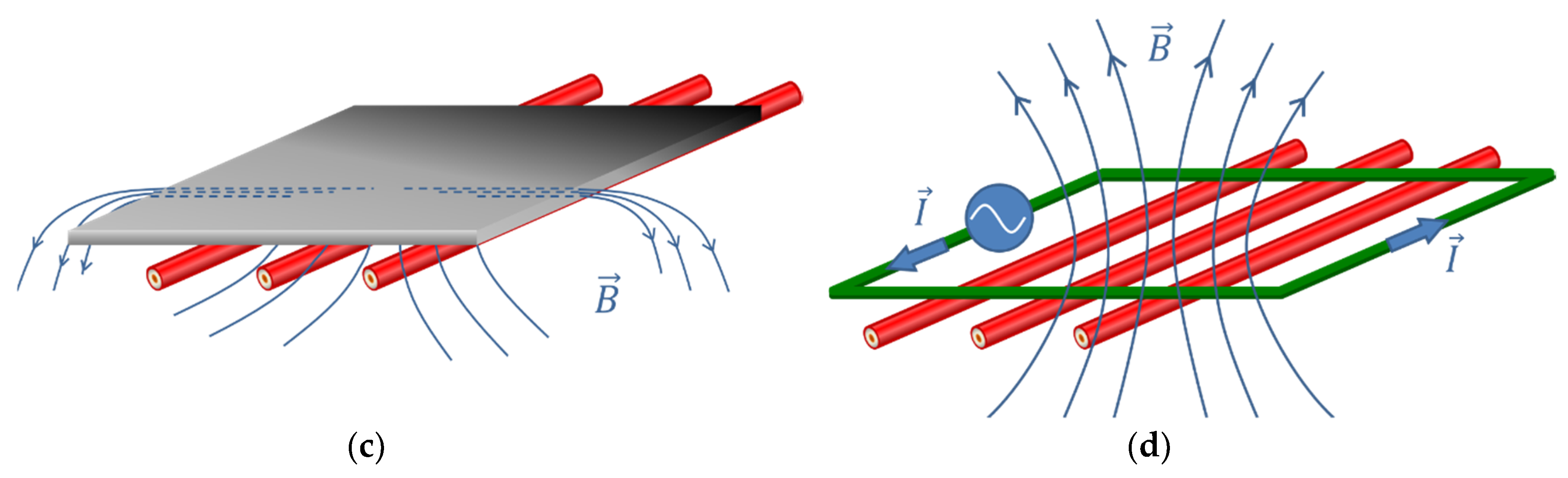
The best, and also the most cost-effective mitigation method for the MF in substations consists of in phase management [13], by keeping the phases mixed as soon as they leave the transformer (Figure 6). This can provide high shielding factors. For this reason, phase cancellation should be the first technique to attempt before trying other techniques that can complement this one, such as the extrinsic techniques that are reviewed in the next section.
In any case, with the aim of improving the overall mitigation when considering the MF emission level of the substations, the first steps to be made refer to a proper organization of the LV conductors in order to decrease the loops provided by the current path [62]. From a practical viewpoint, this objective can be covered by several easy points as follows:
- -
- Preventing useless separation between conductors of different phases;
- -
- Using plaited conductors, with all four conductors, as often as possible;
- -
- Minimizing the length of the cables within the substation;
- -
- Possibly using a compact busbar system, if available, between the transformer and the main LV switchboard.
4. Optimization Applied to Extrinsic Techniques
In the following, the most used optimization techniques applied to extrinsic MF mitigation solutions are presented.
4.1. Passive Loops
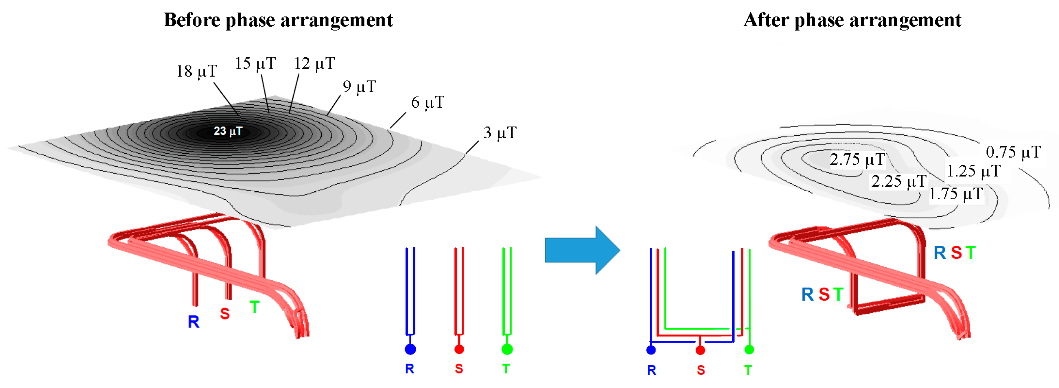
In this technique, one or several coils, or loops, are placed appropriately so that currents are induced by the source of the MF, in accordance with Faraday’s Law [13]. This way, the MF generated by the coils partially compensates the original source MF [23,24,63,64,65]. To achieve better results, many studies have proposed different configurations and arrangements for the loops (independent loops, common conductor loops, enchained loops, etc.), as well as series-compensation of the coils by means of capacitors to increase the induced currents (Figure 7), hence, improving the MF reduction [64,66,67,68,69,70,71,72,73].
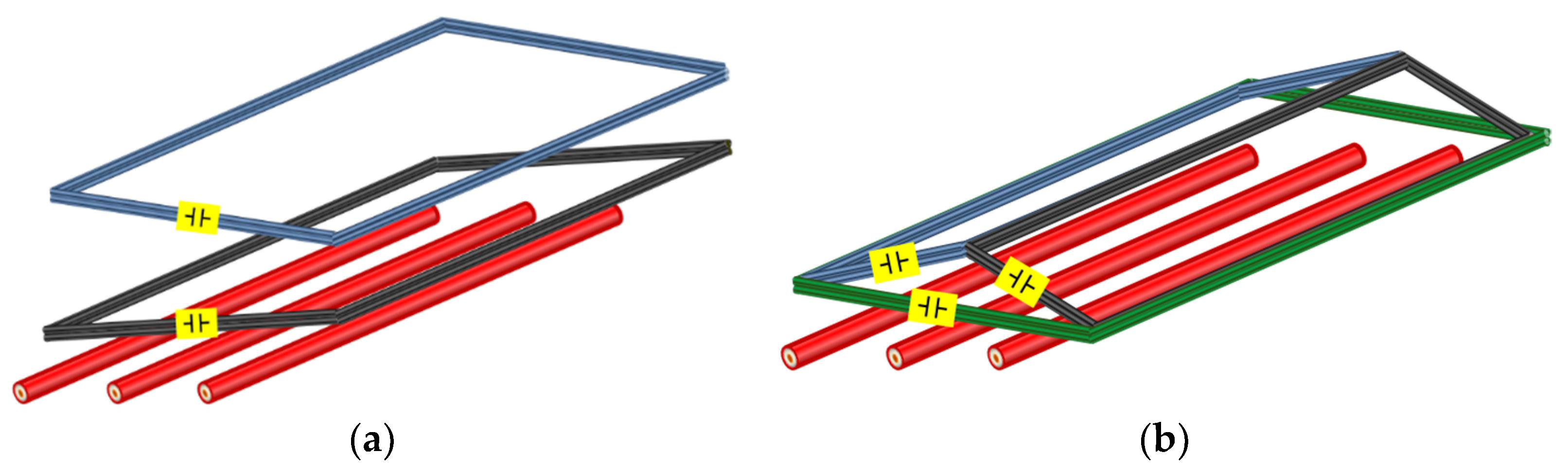
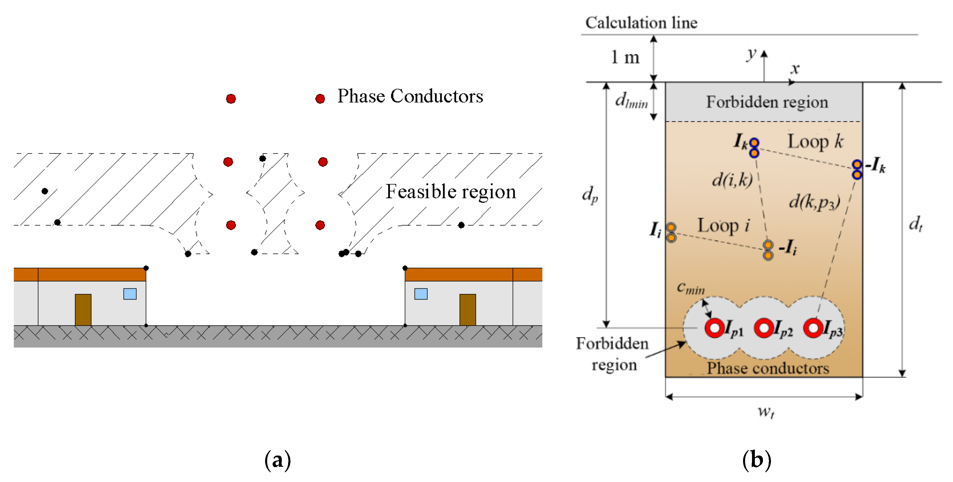
Thus, the main aspects to be considered when designing passive loops are (Figure 8) the following: The number and arrangement of the coils, the number of loops on each coil, the cross section of the conductors to be used in the loops, the clearance between loops (d(i,k)), their position relative to the MF source (d(k,p3)), the presence of forbidden regions, and the capacitors for series-compensation, if required. All this implies a number of parameters that should be defined adequately for each particular situation. Therefore, the need for applying optimization algorithms, to define all these parameters for maximizing the MF reduction in any situation, is clear. In this sense, the MF level in such systems can be computed by means of analytical methods [27,64,65,66,73,74], leading to efficient and fast optimization procedures.
A first example is shown in [69], where a semiheuristic optimization procedure, based on an augmented Lagrangian, for obtaining the optimal location of the passive loops when mitigating the MF generated by an overhead power line is presented. The proposed procedure first requires the determination of the shield location that maximizes the induced currents in the loops. Then, a second optimization is applied to minimize the MF in a certain region, far or close to the power line. Some constraints should be included to limit the line conductor-to-loop conductor clearance. The main conclusions are that the optimal loop arrangements depend on the line configuration and the location of the area to be protected.
In [74,75] a new procedure, based on genetic algorithms (GA), is presented. By means of this new procedure, the optimal location and main properties of the loops are obtained for different arrangements (flat, alternate, and super-bundle) and voltage levels in OHL. Thanks to the flexibility of the GA, two scenarios are considered in relation to the location of the region to be protected, minimizing the MF at one side from the power line (unilateral mitigation) and minimizing the MF at both sides from the power line (bilateral mitigation). In both scenarios, new constraints are implemented for limiting the loop conductor-to-ground clearance and the loop’s maximum height, as well as other restrictions to define forbidden regions due to the presence of dwellings, trainways, etc. The main results show an increase in the MF reduction achieved by the optimized loops, in comparison to previous studies. Additionally, it is observed that the mitigation efficiency achieved depends mainly on the line configuration, followed by the loop design and the voltage levels. Optimal loops are also analyzed in terms of sensitivity, concluding that its mitigation performance may be influenced by small variations in loop’s position, resistance, and compensation capacitance, this effect being more intense in some situations. Eventually, it is also concluded that bilateral mitigation should be avoided if possible, since the mitigation performance is worse in this scenario.
As a consequence of these results, in [76] a new procedure based on GA is presented for more complex situations, such as the mitigation of the MF in UPC by means of passive loops. To this aim, some revisions are applied to the objective function that now maximize the reduction factor (RF), defined as the ratio between the original MF and the mitigated one, at 1 m above ground surface and located at one side of the trench axis. Results show that, for different configuration of series-compensated loops, the mitigation performance of the optimized loops can be much greater than that provided by other passive techniques (such as conductive shields). However, it is also remarked that these optimal solutions are quite sensitive to small variations in loop position and electrical parameters. For this reason, the semiheuristic procedure is improved to obtain the less sensible solution, which ensures a minimum RF in the area of interest.
In any case, all these studies conclude that a better performance is obtained when loops are placed closer to the phase conductors. Nevertheless, this is critical, especially in the case of UPC, since the power losses generated in the loops my affect the current rating of the line. In this sense, [77] goes a step further by including the thermal problem in the semiheuristic optimization procedure proposed in [76]. This way, new constraints may be included to limit the maximum temperature of line conductors so that loops can be closer to them, with no effect on the line current rating. Additionally, the objective function in the GA is also modified to maximize the ratio RFmin-Cost, where RFmin is the RF provided by the optimal loop, in the worst situation after considering variations of ±5% in loop positions and electrical parameters, and Cost is the total cost of the loops, including the operational cost. This way, new constraints are included to consider both technical and economic aspects in the optimization procedure. Consequently, the optimized loops obtained are able to guarantee a minimum RF in the area of interest, and all this with the minimum possible cost.
It should be remarked that passive loops have been also applied to more specific situations, such as joint bays in UPC. In this sense, [78] proposes the optimization of passive loops by means of GA, comparing its performance to the one provided by other typical loop arrangements that are usually used in these installations [71]. As a result, this comparison clearly shows how the mitigation performance of the loops can be noticeably increased by means of an optimized design.
More recently, new studies have used other optimization algorithms that have paid much attention in optimization research today. One example are nature-inspired meta-heuristic algorithms, like PSO, that have shown to be faster than GA [79]. In this sense, [65] presents a new optimization procedure, based on PSO, for obtaining the loop position for minimizing the induced voltages in aerial pipes installed close to 400 kV OHL. For this purpose, one or two passive loops, made of conductive or ferromagnetic conductors, are installed. From this study it is concluded that a better performance is obtained if conductors have a permeability greater than 1.
4.2. Active Loops
Unlike passive loops, active loops are supplied by external power sources to inject the required current (magnitude and phase) at any moment, being able to provide a much higher mitigation reduction. This solution has been analyzed mainly in OHL [26,27,80,81] and MV/LV substations [28,82,83]. However, this mitigation system may be much more complex and more expensive than passive ones. Thus, apart from the type of loops, its number, position, and cross section, new variables should be included in the optimization problem, such as the magnitude and phase of the injected currents. Consequently, the use of an optimization procedure is very helpful for obtaining the optimal configuration and position of the active loops that require the smallest power source for providing a certain MF mitigation. To this aim, and thanks to the simple geometry of the shielding system, the evaluation of the MF can be addressed by means of analytical expressions, mainly based on the Biot–Savart Law [13], so that different optimization procedures can be implemented easily, as described next.
Regarding its application to OHL, a first approach in active loop optimization is developed in [27], where the position of the active loop is first obtained by means of an annealing optimization algorithm, considering the loops as passive loops. Then, the current that minimizes the MF at a certain region is calculated. However, it is concluded that further optimization is required for selecting the optimum conductor for the loops.
A full optimization procedure is presented later in [29], where the positions and currents of active loops are optimally obtained, by means of a GA, for mitigating the MF of an overhead line. This way, the mitigation system can be optimized in an easy way for any line configuration and area of interest.
As shown in the passive techniques design, the advantages presented by the GA makes this optimization algorithm the most employed when designing mitigation systems. In this sense, [84] presents the design and optimization procedure of an active loop system based on a GA, employing a low-cost hardware, such as Arduino. In this work, the model of the MF source is obtained first and then the position and current of the active loop is derived by means of the GA, for a particular loading condition of the MF source. Finally, the control system ensures the suitable current to be injected in the loops at any loading conditions. The performance of this prototype is later improved by implementing a “Perturb and Observe” algorithm in the control system [85].
Recently, for the case of OHL, new advances have been developed through the means of a different optimization algorithm. In particular, in [81,86,87,88] the number, configuration, arrangement, and loop currents are derived by means of a multi-objective optimization problem that is solved by multi-agent multiswarm stochastic optimization, based on Pareto optimal solutions. In [88] this procedure is improved to take into account uncertainties in the parameters of the loops (positions, currents, etc.) as well as in other parameters related to the area to be protected and the location to be installed at. This is done by the analysis of the space-time characteristic of the MF generated by the source. Finally, this procedure is validated experimentally in [81], showing differences lower than 20% between the MF values derived from simulations and experimental measurements. Additionally, it is observed that, as expected, the mitigation efficiency depends on the location of the MF sensors.
Nonetheless, active loops have also been optimized for the MF mitigation generated by MV/LV substations. In this sense, in [28] an optimization design based on GAs is presented for minimizing the MF levels in a target value outside the cabin. The procedure is applied to a full 3D model of the substation, wherein all its elements need to be adequately modeled first. Then, the location of the active loop inside the cabin is derived from the optimization algorithm.
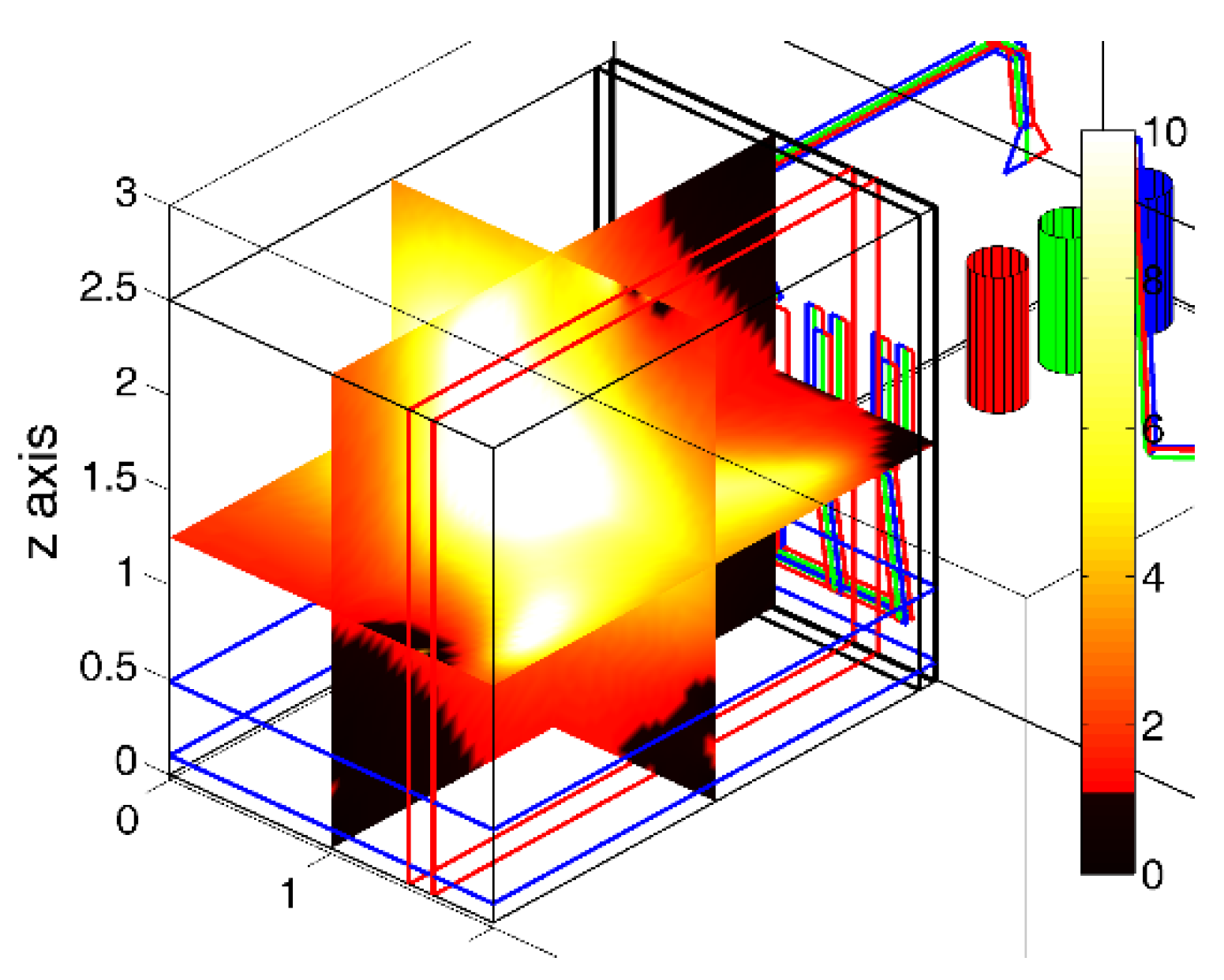
A similar procedure is later presented in [82,83], where GA is used to optimize different active loop configurations for the MF mitigation in different volumes around and above a MV/LV substation. Opposite to [28], in this work, the active system is composed of three pairs of loops installed in the walls of the volume to be protected, with each pair supplied by one power source. The position of each loop and the currents to be injected are then derived for minimizing the average MF inside a particular inspection area, inside the volume to be shielded. The main conclusions show that a great reduction can be obtained. Furthermore, unlike other passive mitigation systems, this procedure helps focus the maximum MF mitigation efficiency in any region inside the target volume (Figure 9).
4.3. Passive Shields
The use of metallic shields is one of the passive solutions presented earlier and has been extensively used on its own, or in combination with other mitigation systems, for mitigating the MF in buildings close to OHL [13] and in the mitigation of the MF generated by UPC [38,71,72,89,90,91] and MV/LV substations [92,93,94,95]. In literature in the last decades, different geometries have been proposed and analyzed concerning their application for electrical applications, employing conductive and/or ferromagnetic materials [25,38,91,94,95,96,97,98,99]. Thus, for each shield geometry and for a particular location, a number of parameters must be specified for ensuring the required MF mitigation (shield dimensions, position relative to the source, and material properties). In this sense, there are no analytical expressions for evaluating the MF reduction provided by every possible shielding configuration, due to its complex geometric and material properties. There are only few cases where analytical expressions are derived [96,97,100,101], but these are usually based on simplified situations (infinite width shields, perfect magnetic or perfect electric materials, ferromagnetic cylindrical shields, etc.). So, numerical methods, such as FEM, are frequently preferred to address this problem [38,89,91,94,99,102,103]. Nevertheless, from the optimization point of view, this may imply more computational requirements and longer computation time, depending on the complexity of the analyzed system, so obtaining new analytical formulae for more realistic situations would lead to faster and more efficient optimization procedures for this mitigation technique. Nonetheless, new numerical approaches have been presented recently that may help in this task in the near future [104,105,106,107] since they drastically reduce the number of unknowns when dealing with thin shields, in comparison with FEM.
In the literature there are many studies focused on optimizing shields for industrial applications, such as induction heating [108] and shielding electronic equipment [109]. However, few studies can be found regarding the optimization of magnetic shields applied to power systems. Thus, for power installations, most of the studies have tackled this problem by means of parametric analyses [25,38,90,91,96,98], where the main conclusions highlight that better a mitigation performance is obtained when the shield is larger and closer to the MF source. However, in some situations, like UPC, the closer the shield the higher the induced losses and, hence, the temperature. As a consequence, the presence of the shield may affect the current rating of the line [19,38,91]. Therefore, the need for an optimization process for optimizing the shield, not only in terms of MF mitigation efficiency but also in total cost (including operation cost) and limited impact on the current rating of the MF source, is clear. However, shielding optimization has only been considered for UPC. In this sense, a first approach is presented in [102], where a continuum gradient-based shape optimization procedure for conductive shields installed over UPC is proposed. Its main objective is to optimize the shape of the plates for maximal MF reduction and a minimal amount of material for the shield. For this tasks, numerical simulations are performed by FEM and additional constrains are included to obtain symmetric shapes for the shield. The main results conclude that the optimal shields achieve high MF mitigation reduction. However, obtained shapes are complex, making its placement in actual locations very difficult. Additionally, thermal effects are not considered in the optimization procedure.
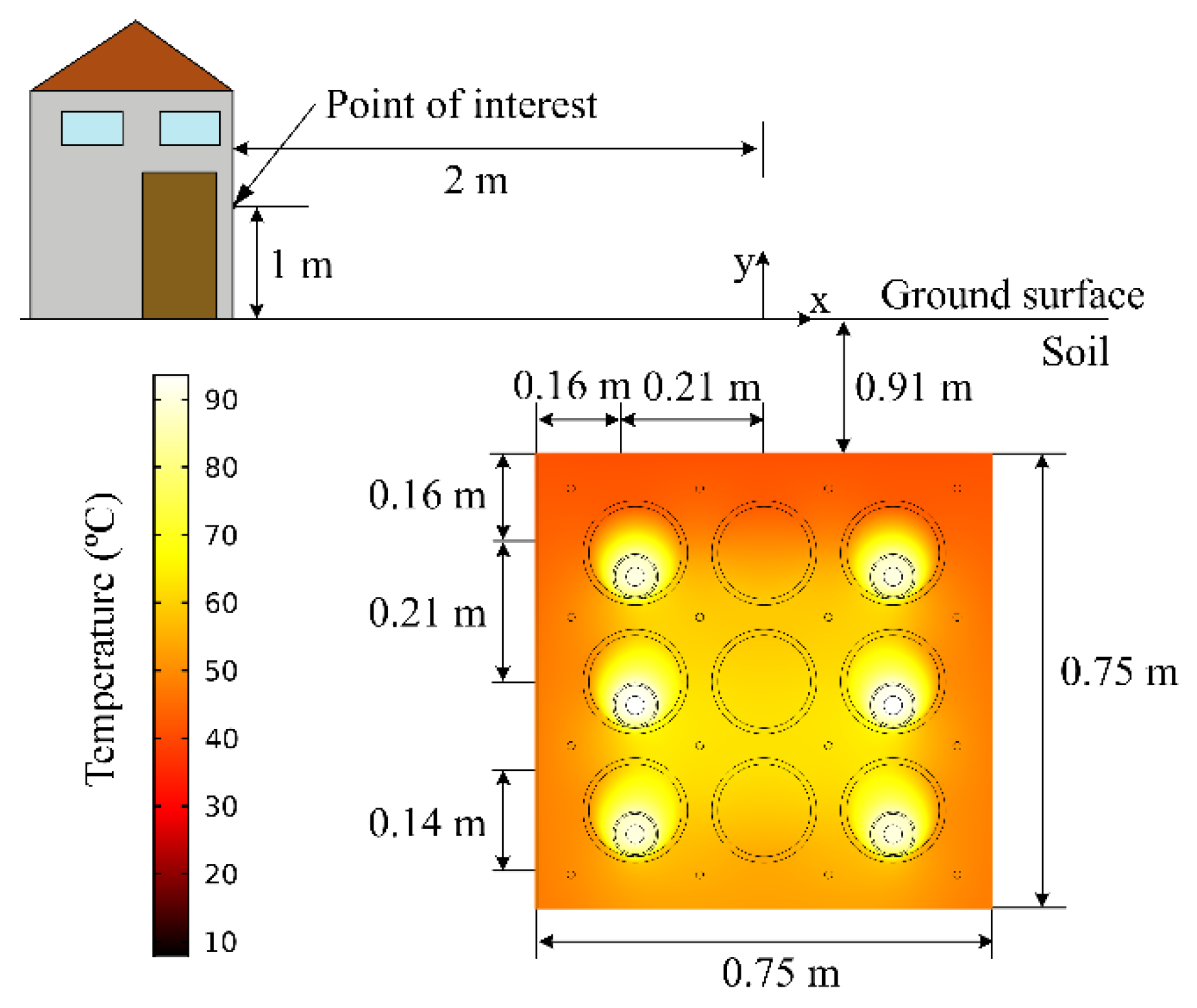
On the other hand, [89] proposes an optimization process, based on a GA, for the minimization of the cost of ferromagnetic and conductive shields when applied to UPC duct banks, reducing the MF above ground to below a certain level without limiting the current rating of the cables. The proposed procedure starts by obtaining the conductor arrangement which provides the minimum MF at the region to be shielded (located above ground and at one side of the trench). Then, the optimization algorithm determines the shield dimensions and positions with the lowest possible cost. Here, the thermal problem is considered to limit the impact on the current rating of the lines to be shielded (Figure 10). Additionally, non-linear properties are considered for the ferromagnetic plates, so simulations are performed by means of FEM. The conclusions highlight that better results, in terms of efficiency and cost, are obtained for certain combinations of shield shape, shield material, and conductor arrangement. Furthermore, results show a good performance when additional circuits are installed sometime later in the shielded duct bank.
5. Conclusions
The motivation for this work stems from challenges facing the electrical facilities in determining optimal, cost-effective, and safety measures to avoid non-desirable magnetic field exposures. In this way, this paper addresses optimization methods for minimizing extremely low frequency (50/60Hz) magnetic fields. Specifically, optimization methods are reviewed in accordance with their application to overhead transmission lines, underground power cables, and MV/LV substations. Meanwhile, the optimization methods are surveyed following the classification of intrinsic techniques and extrinsic techniques. Despite that no single optimization algorithm can solve all optimization problems on this topic, the overview of the different available algorithms, typically applied for mitigating magnetic fields, will help to select the appropriate algorithm for the problem at hand.
It can be concluded that most of the optimization proposals to achieve optimal cost-effective magnetic field mitigation are mainly based on parametric studies. Alternatively, a great variety of optimization algorithms (differential evolution, augmented Lagrangian, continuum gradient, etc.) have also been used. Among all of them, the genetic algorithm is highlighted by its efficiency but, in recent times, it is progressively being replaced by the particle swarm optimization technique.
Finally, it is also concluded that the use of numerical methods, when dealing with passive shields, may burden the computation time and efficiency of any optimization procedure and it may be more appropriate to use analytical expressions when possible.
Author Contributions
J.C.B.-R. and J.C.d.-P.-L. conceived the topic, conducted the literature survey, and wrote a preliminary version in combination with P.C.-R., who provided valuable data, gave helpful comments, and revised the paper. All the authors were involved in preparing the final version of this manuscript. J.C.d.-P.-L. supervised the whole work.
Funding
This research was funded by the Agencia Estatal de Investigación and Fondo Europeo de Desarrollo Regional (AEI/FEDER, UE) under the project ENE2017-89669-R and by the Universidad de Sevilla (VI PPIT-US) under grant 2018/00000740.
Conflicts of Interest
The authors declare no conflict of interest.
References
- WHO/IARC. Monograph 80: Non-Ionising Radiation, Static and Extremely Low-Fequency Electric and Magnetic Fields; WHO/IARC: Lyon, France, 2002; Volume 80. [Google Scholar]
- Rao, S.; Sathyanarayanan, A.; Nandwani, U. EMI problems for medical devices. In Proceedings of the International Conference on Electromagnetic Interference and Compatibility, Bangalore, India, 23 February 2002; IEEE: New Delhi, India, 1999; pp. 21–24. [Google Scholar]
- Shwehdi, M.H. A practical study of an electromagnetic interference (EMI) problem from Saudi Arabia. In Proceedings of the Large Engineering Systems Conference on Power Engineering (IEEE Cat. No.04EX819), Halifax, NS, Canada, 28–30 July 2004; pp. 162–169. [Google Scholar]
- Bontá, D.M.; Director, D.; Richard Neutra, R.; Vincent DelPizzo, D.; Geraldine Lee, G.M.; Lee, S.; Shen Liu, K.; Shaw, G.; Smith, D.; Marilyn Underwood, D.C.; et al. An Evaluation of the Possible Risks from Electric and Magnetic Fields (EMFS) from Power Lines, Internal Wiring, Electrical Occupations, and Appliances; California Department of Industrial Relations: Oakland, CA, USA, 2002.
- Van Loock, W. Elementary effects in humans exposed to electromagnetic fields and radiation. In Proceedings of the IEEE 2009 5th Asia-Pacific Conference on Environmental Electromagnetics, Xian, China, 16–20 September 2009; pp. 221–224. [Google Scholar]
- Florea, G.A.; Dinca, A.; Gal, S.I.A. An original approach to the biological impact of the low frequency electromagnetic fields and proofed means of mitigation. In Proceedings of the 2009 IEEE Bucharest PowerTech, Bucharest, Romania, 28 June–2 July 2009; pp. 1–8. [Google Scholar]
- ICNIRP (International Commission on Non-Ionizing Radiation Protection). Guidelines for Limiting Exposure to Time-Varying Electric and Magnetic Fields (1 Hz to 100 kHz). Health Phys. 2010, 99, 818–836. [Google Scholar] [CrossRef]
- IEEE PC95.1 Draft Standard for Safety Levels with Respect to Human Exposure to Electric, Magnetic and Electromagnetic Fields, 0 Hz to 300 GHz; IEEE: Piscataway, NJ, USA, 2018.
- Amoon, A.T.; Crespi, C.M.; Ahlbom, A.; Bhatnagar, M.; Bray, I.; Bunch, K.J.; Clavel, J.; Feychting, M.; Hémon, D.; Johansen, C.; et al. Proximity to overhead power lines and childhood leukaemia: An international pooled analysis. Br. J. Cancer 2018, 119, 364–373. [Google Scholar] [CrossRef] [PubMed]
- Hossam-Eldin, A.; Youssef, K.; Karawia, H. Measurements and evaluation of adverse health effects of electromagnetic fields from low voltage equipments. In Proceedings of the IEEE 2008 12th International Middle-East Power System Conference, Aswan, Egypt, 12–15 March 2008; pp. 436–440. [Google Scholar]
- Swanson, J. EMF Exposure Standards Applicable in Europe and Elsewhere: Environment & Society Working Group; Connecticut Siting Council: New Britain, CT, USA, 2006.
- Hernández Jiménez, V.J.; Castronuovo, E.D.; Sánchez, I. Optimal statistical calculation of power cables disposition in tunnels, for reducing magnetic fields and costs. Int. J. Electr. Power Energy Syst. 2018, 103, 360–368. [Google Scholar] [CrossRef]
- CIGRÉ Working Group C4.204. Mitigation Techniques of Power-Frequency Magnetic Fields Originated from Electric Power Systems. CIGRÉ Technical Brochure; CIGRÉ: Paris, France, August 2009; ISBN 978-2-85873-060-5. [Google Scholar]
- Bignucolo, F.; Coppo, M.; Savio, A.; Turri, R. Use of rod compactors for high voltage overhead power lines magnetic field mitigation. Energies 2017, 10, 1381. [Google Scholar] [CrossRef]
- Ranković, A. Novel multi-objective optimization method of electric and magnetic field emissions from double-circuit overhead power line. Int. Trans. Electr. Energy Syst. 2017, 27, e2243. [Google Scholar] [CrossRef]
- Hedtke, S.; Pfeiffer, M.; Franck, C.M.; Zaffanella, L.; Chan, J.; Bell, J. Audible noise of hybrid AC / DC overhead lines: Comparison of different prediction methods and conductor arrangements. Epri’s High-Volt. Direct Curr. Flex. Ac Transm. Syst. Conf. 2015, 1, 1–8. [Google Scholar]
- Electric Power Research Institute. EPRI Transmission Line Reference Book: 115–345-kV Compact Line Design: The “Blue Book”; EPRI: Palo Alta, CA, USA, 2008. [Google Scholar]
- Straumann, U.; Straumann, U.; Franck, C.M. Discussion of Converting a Double-Circuit AC Overhead Line to an AC/DC Hybrid Line with Regard to Audible Noise; CIGRÉ: Paris, France, 2011. [Google Scholar]
- CIGRÉ Working Group B1.23. Impact of EMF on Current Ratings and Cable Systems; CIGRÉ Technical Brochure; CIGRÉ: Paris, France, 2013; ISBN 978-2-85873-254-8. [Google Scholar]
- Cruz Romero, P.; Izquierdo Mitchell, C.; Burgos Payan, M. Optimal split-phase configurations. In Proceedings of the 2001 IEEE Porto Power Tech Proceedings (Cat. No.01EX502), Porto, Portugal, 10–13 September 2001; Volume 3, p. 5. [Google Scholar] [CrossRef]
- Pettersson, P. Principles in transmission line magnetic field reduction. IEEE Trans. Power Deliv. 1996, 11, 1587–1593. [Google Scholar] [CrossRef]
- Dawoud, M.M.; Habiballah, I.O.; Farag, A.S.; Firoz, A. Magnetic field management techniques in transmission underground cables. Electr. Power Syst. Res. 1999, 48, 177–192. [Google Scholar] [CrossRef]
- Shperling, B.; Menemenlis-Hopkins, L.; Fardanesh, B.; Clairmont, B.; Child, D. Reduction of magnetic fields from transmission lines using passive loops. In Proceedings of the CIGRÉ Session, Paris, France, 25–31 August 1996; pp. 36–103. [Google Scholar]
- Yamazaki, K.; Kawamoto, T.; Fujinami, H. Requirements for power line magnetic field mitigation using a passive loop conductor. IEEE Trans. Power Deliv. 2000, 15, 646–651. [Google Scholar] [CrossRef]
- Farag, A.S.; Dawoud, M.M.; Habiballah, I.O. Implementation of shielding principles for magnetic field management of power cables. Electr. Power Syst. Res. 2002, 48, 193–209. [Google Scholar] [CrossRef]
- Reta-Hernández, M.; Karady, G.G. Attenuation of low frequency magnetic fields using active shielding. Electr. Power Syst. Res. 1998, 45, 57–63. [Google Scholar] [CrossRef]
- Cruz Romero, P.; Izquierdo, C.; Burgos, M.; Ferrer, L.F.; Soto, F.; LLanos, C.; Pacheco, J.D. Magnetic field mitigation in power lines with passive and active loops. In Proceedings of the CIGRÉ Session, Paris, France, 25–30 August 2002. [Google Scholar]
- Garzia, F.; Geri, A. Active shielding design in full 3D space of indoor MV/LV substations using genetic algorithm optimization. In Proceedings of the 2003 IEEE Symposium on Electromagnetic Compatibility. Symposium Record (Cat. No.03CH37446), Boston, MA, USA, 18–22 August 2003; Volume 1, pp. 197–202. [Google Scholar]
- Celozzi, S.; Garzia, F. Active shielding for power-frequency magnetic field reduction using genetic algorithms optimisation. IEE Proc. Sci. Meas. Technol. 2004, 151, 298–304. [Google Scholar] [CrossRef]
- Barsali, S.; Giglioli, R.; Poli, D. Active shielding of overhead line magnetic field: Design and applications. Electr. Power Syst. Res. 2014, 110, 55–63. [Google Scholar] [CrossRef]
- IEC-60287-1-1 Standard. Electric Cables–Calculation of Current Rating–Part 1: Current Rating Equations (100% Load Factor) and Calculation of Losses, Section 1: General; International Electrotechnical Commission: Geneva, Switzerland, 2006. [Google Scholar]
- IEC-60287-2-1 Standard. Electric Cables–Calculation of Current Rating–Part 2: Thermal Resistance–Section 1: Calculation of Thermal Resistance; International Electrotechnical Commission: Geneva, Switzerland, 2015. [Google Scholar]
- de León, F.; Anders, G.J. Effects of backfilling on cable ampacity analyzed with the finite element method. IEEE Trans. Power Deliv. 2008, 23, 537–543. [Google Scholar] [CrossRef]
- Naskar, A.K.; Bhattacharya, N.K.; Sarkar, D. Transient thermal analysis of underground power cables using two dimensional finite element method. Microsyst. Technol. 2018, 24, 1279–1293. [Google Scholar] [CrossRef]
- Holyk, C.; Anders, G.J. Power Cable Rating Calculations-A Historical Perspective [History]. IEEE Ind. Appl. Mag. 2015, 21, 6–64. [Google Scholar] [CrossRef]
- Hoerauf, R. Ampacity application considerations for underground cables. IEEE Trans. Ind. Appl. 2016, 52, 4638–4645. [Google Scholar] [CrossRef]
- Mozan, M.A.; El-Kady, M.A.; Mazi, A.A. Advanced thermal analysis of underground power cables. In Proceedings of the Fifth International Middle East Power Conference MEPCON’97, Alexandria, Egypt, 4–6 January 1997; pp. 506–510. [Google Scholar]
- del-Pino-López, J.C.; Cruz-Romero, P. Influence of different types of magnetic shields on the thermal behavior and ampacity of underground power cables. IEEE Trans. Power Deliv. 2011, 26, 2659–2667. [Google Scholar] [CrossRef]
- del-Pino-López, J.C.; Cruz-Romero, P.; Serrano-Iribarnegaray, L. Impact of electromagnetic losses in closed two-component magnetic shields on the ampacity of underground power cables. Prog. Electromagn. Res. 2013, 135, 601–625. [Google Scholar] [CrossRef]
- Abdurakhmanov, A.M.; Zimin, K.A.; Ryabchenko, B.N.; Tokarskiy, A.Y.; Rubtsova, N.B. Solving the Environmental Electromagnetic Safety Issues in 110–500 kV AC Cable Power Lines. In Proceedings of the CIGRÉ Session, Paris, France, 26–31 August 2018. [Google Scholar]
- Kladas, A.; Diamantis, A.; Damatopoulou, T.; Dikaiakos, C.; Papaioannou, G.; Michos, D. Over Head Transmission Lines and High Voltage Substations Electromagnetic Field Analysis and Design Considerations for Minimizing External Impacts. In Proceedings of the CIGRÉ Session, Paris, France, 26–31 August 2018; pp. 1–14. [Google Scholar]
- Stewart, J.R.; Dale, S.J.; Klein, K.W. Magnetic field reduction using high phase order lines. IEEE Trans. Power Deliv. 1993, 8, 628–636. [Google Scholar] [CrossRef]
- Tsalemis, D.; Tsanakas, D.; Milias-Argitis, J.; Agoris, D. Optimum arrangements of the phase conductors of overhead transmission lines for the electric field minimization. In Proceedings of the International Symposium on High Voltage Engineering ISH 97, Montreal, QC, Canada, 25–29 August 1997; pp. 97–100. [Google Scholar]
- Deželak, K.; Jakl, F.; Štumberger, G. Arrangements of overhead power line phase conductors obtained by Differential Evolution. Electr. Power Syst. Res. 2011, 81, 2164–2170. [Google Scholar] [CrossRef]
- Farag, A.S.; Bakhashwain, J.M.; Al-Shehri, A.; Cheng, T.C.; Gao, Y. Bundled conductor configuration optimization for compact transmission lines incorporating electromagnetic fields management. Energy Convers. Manag. 1998, 39, 1053–1071. [Google Scholar] [CrossRef]
- Tsanakas, D.; Filippopoulos, G.; Voyatzakis, J.; Kouvarakis, G. Compact and optimum phase conductor arrangement for the reduction of electric and magnetic fields of overhead lines. In Proceedings of the CIGRÉ Session, Paris, France, 25–30 August 2000; pp. 36–103. [Google Scholar]
- Dahab, A.A.; Amoura, F.K.; Abu-Elhaija, W.S. Comparison of Magnetic-Field Distribution of Noncompact and Compact Parallel Transmission-Line Configurations. IEEE Trans. Power Deliv. 2005, 20, 2114–2118. [Google Scholar] [CrossRef]
- Ranković, A.; Mijailović, V.; Rozgić, D.; Cetenović, D. Optimization of electric and magnetic field emissions produced by independent parallel overhead power lines. Serb. J. Electr. Eng. 2017, 14, 199–216. [Google Scholar] [CrossRef]
- Costea, M.; Bǎran, I. Side effects of the power frequency magnetic field mitigation. In Proceedings of the 2017 10th International Symposium on Advanced Topics in Electrical Engineering, ATEE 2017, Bucharest, Romania, 23–25 March 2017; pp. 330–335. [Google Scholar]
- El Dein, A.Z. Optimal Arrangement of Egyptian Overhead Transmission Lines’ Conductors Using Genetic Algorithm. Arab. J. Sci. Eng. 2014, 39, 1049–1059. [Google Scholar] [CrossRef]
- Salameh, M.S.H.A.; Nejdawi, I.M.; Alani, O.A.; Commission, E.R.; Contracting, B.G. Using the Nonlinear Particle Swarm Optimization (PSO) Algorithm To Reduce the Magnetic Fields From Overhead High Voltage Transmission Lines. IJRRAS 2010, 4, 18–31. [Google Scholar]
- Konak, A.; Coit, D.W.; Smith, A.E. Multi-objective optimization using genetic algorithms: A tutorial. Reliab. Eng. Syst. Saf. 2006, 91, 992–1007. [Google Scholar] [CrossRef]
- Ippolito, L.; Siano, P. Using multi-objective optimal power flow for reducing magnetic fields from power lines. Electr. Power Syst. Res. 2003, 68, 93–101. [Google Scholar] [CrossRef]
- Kalyanmoy, D. Multi-Objective Optimization Using Evolutionary Algorithms; John Wiley Sons, Inc.: New York, NY, USA, 2001; ISBN 047187339X. [Google Scholar]
- Karady, G.G.; Nunez, C.V.; Raghavan, R. The feasibility of magnetic field reduction by phase relationship optimization in cable systems. IEEE Trans. Power Deliv. 1998, 13, 647–654. [Google Scholar] [CrossRef]
- Lai, G.G.; Huang, H.M. Optimal Connection of Power Transmission Lines With Underground Power Cables to Minimize Magnetic Flux Density Using Genetic Algorithms. IEEE Trans. Power Deliv. 2008, 23, 1553–1560. [Google Scholar] [CrossRef]
- Giaccone, L. Optimal layout of parallel power cables to minimize the stray magnetic field. Electr. Power Syst. Res. 2016, 134, 152–157. [Google Scholar] [CrossRef] [Green Version]
- Almeida, M.E.; Maló Machado, V.; Guerreiro das Neves, M. Mitigation of the magnetic field due to underground power cables using an optimized grid. Eur. Trans. Electr. Power 2011, 21, 180–187. [Google Scholar] [CrossRef]
- Mimos, E.I.; Tsanakas, D.K.; Tzinevrakis, A.E. Optimum phase configurations for the minimization of the magnetic fields of underground cables. Electr. Eng. 2010, 91, 327–335. [Google Scholar] [CrossRef]
- Lai, G.G.; Yang, C.; Su, C.-T. Estimation and management of magnetic flux density produced by underground cables in multiple-circuit feeders. Eur. Trans. Electr. Power 2010, 20. [Google Scholar] [CrossRef]
- Rachek, M.; Larbi, S.N. Magnetic eddy-current and thermal coupled models for the finite-element behavior analysis of underground power cables. IEEE Trans. Magn. 2008, 44, 4739–4746. [Google Scholar] [CrossRef]
- Fulchiron, D.; Delaballe, J. Reduction of the Low Frequency EMF Emission of MV/LV Substations. In Proceedings of the 17th International Conference on Electricity Distribution (CIRED), Barcelona, Spain, 12–15 May 2003. [Google Scholar]
- Saied, M.M. Canceling the Power Frequency Magnetic and Electric Fields of Power Lines. IETE J. Educ. 2014, 54, 90–99. [Google Scholar] [CrossRef]
- Rebolini, M.; Forteleoni, M.; Capra, D. Passive cancellation loops: Case study, model simulation and field test on a real HV overhead line in Italy: Electromagnetic computation and optimization. In Proceedings of the 2017 AEIT International Annual Conference: Infrastructures for Energy and ICT: Opportunities for Fostering Innovation, AEIT 2017, Cagliari, Italy, 20–22 September 2017; pp. 1–6. [Google Scholar]
- Djekidel, R.; Bessedik, S.A.; Spiteri, P.; Mahi, D. Passive mitigation for magnetic coupling between HV power line and aerial pipeline using PSO algorithms optimization. Electr. Power Syst. Res. 2018, 165, 18–26. [Google Scholar] [CrossRef]
- Walling, R.; Paserba, J.J.; Burns, C.W. Series-capacitor compensated shield scheme for enhanced mitigation of transmission line magnetic fields. In Proceedings of the 1991 IEEE Power Engineering Society Transmission and Distribution Conference, Dallas, TX, USA, 22–27 September 1991; pp. 769–775. [Google Scholar]
- TR-105571. Magnetic Field Management of Overhead Transmission Lines: Field Reduction Using Cancellation Loops; EPRI: Palo Alto, CA, USA, 1995. [Google Scholar]
- Larsson, A.; Jonsson, U.; Sjödin, J. Design, test and cost of a magnetic field cancellation loop near swedish 400 kV line. In Proceedings of the Power Tech, Stockholm, Sweden, 18–22 June 1995. [Google Scholar]
- Cruz-Romero, P.; Izquierdo, C.; Burgos, M. Optimum passive shields for mitigation of power lines magnetic field. IEEE Trans. Power Deliv. 2003, 18, 1357–1362. [Google Scholar] [CrossRef]
- Cruz-Romero, P.; Hoeffelman, J.; del-Pino-López, J.C. Passive loop-based mitigation of magnetic fields from undergound power cable. IEEE Latin Am. Trans. 2008, 6, 59–65. [Google Scholar] [CrossRef]
- Canova, A.; Bavastro, D.; Freschi, F.; Giaccone, L.; Repetto, M. Magnetic shielding solutions for the junction zone of high voltage underground power lines. Electr. Power Syst. Res. 2012, 89, 109–115. [Google Scholar] [CrossRef]
- Frezzi, P.; Hug, R.; Grant, J.; Klingler, A. Passive magnetic field compensation of existing underground cables. In Proceedings of the IEEE International Symposium on Electromagnetic Compatibility, Wroclaw, Poland, 5–9 September 2016; pp. 876–881. [Google Scholar]
- Brandão Faria, J.A.; Almeida, M.E. Accurate calculation of magnetic-field intensity due to overhead power lines with or without mitigation loops with or without capacitor compensation. IEEE Trans. Power Deliv. 2007, 22, 951–959. [Google Scholar] [CrossRef]
- Cruz-Romero, P.; Riquelme-Santos, J.; del-Pino-López, J.C.; de-la-Villa-Jaén, A.; Ramos, J.L.M. A comparative analysis of passive loop-based magnetic field mitigation of overhead lines. IEEE Trans. Power Deliv. 2007, 22, 1773–1781. [Google Scholar] [CrossRef]
- Cruz-Romero, P.; Riquelme-Santos, J.; de-la-Villa-Jaén, A.; Martínez, J.L. Ga-based passive loop optimization for magnetic field mitigation of transmission lines. Neurocomputing 2007, 70, 2679–2686. [Google Scholar] [CrossRef]
- del-Pino-López, J.C.; Cruz-Romero, P. The effectiveness of compensated passive loops for mitigating underground power cable magnetic fields. IEEE Trans. Power Deliv. 2011, 26. [Google Scholar] [CrossRef]
- del-Pino-López, J.C.; Cruz-Romero, P. Thermal Effects on the Design of Passive Loops to Mitigate the Magnetic Field Generated by Underground Power Cables. IEEE Trans. Power Deliv. 2011, 26, 1718–1726. [Google Scholar] [CrossRef]
- Canova, A.; Freschi, F.; Giaccone, L.; Guerrisi, A.; Repetto, M. Magnetic field mitigation by means of passive loop: Technical optimization. Compel Int. J. Comput. Math. Electr. Electron. Eng. 2012, 31, 870–880. [Google Scholar] [CrossRef]
- Król, K.; Machczyński, W. Optimization of electric and magnetic field intensities in proximity of power lines using genetic and particle swarm algorithms. Arch. Electr. Eng. 2018, 67, 829–843. [Google Scholar] [CrossRef]
- Jonsson, U.; Larsson, A.; Sjodin, J.-O. Optimized reduction of the magnetic field near Swedish 400 KV lines by advanced control of shield wire currents. Test results and economic evaluation. IEEE Trans. Power Deliv. 1994, 9, 961–969. [Google Scholar] [CrossRef]
- Bovdui, I.; Kuznetsov, B.; Voloshko, A.; Nikitina, T. Experimental Research of Effectiveness of Active Shielding System of Overhead Transmission Lines Magnetic Field with Various Control Algorithms. In Proceedings of the 2018 IEEE 3rd International Conference on Intelligent Energy and Power Systems (IEPS), Kharkiv, Ukraine, 10–14 September 2018; pp. 151–154. [Google Scholar]
- del-Pino-López, J.C.; Giaccone, L.; Canova, A.; Cruz-Romero, P. Design of active loops for magnetic field mitigation in MV/LV substation surroundings. Electr. Power Syst. Res. 2015, 119, 337–344. [Google Scholar] [CrossRef]
- del-Pino-López, J.C.; Giaccone, L.; Canova, A.; Cruz-Romero, P. Ga-based active loop optimization for magnetic field mitigation of MV/LV substations. IEEE Lat. Am. Trans. 2014, 12, 1055–1061. [Google Scholar] [CrossRef]
- Canova, A.; del-Pino-López, J.C.; Giaccone, L.; Manca, M. Active shielding system for ELF magnetic fields. IEEE Trans. Magn. 2015, 51. [Google Scholar] [CrossRef]
- Canova, A.; Giaccone, L. Real-time optimization of active loops for the magnetic field minimization. Int. J. Appl. Electromagn. Mech. 2018, 56, 97–106. [Google Scholar] [CrossRef]
- Kuznetsov, B.I.; Turenko, A.N.; Nikitina, T.B.; Voloshko, A.V.; Kolomiets, V.V. Method of synthesis of closed-loop systems of active shielding magnetic field of power transmission lines. Tekhnichna Elektrodynamika 2016, 4, 8–10. [Google Scholar] [CrossRef]
- Voloshko, A.V.; Bovdyj, I.V.; Nikitina, T.B.; Vinichenko, E.V.; Kuznetsov, B.I.; Kobilyanskiy, B.B. Synthesis of Active Screening System of Magnetic Field of High Voltage Power Lines of Different Design Taking Into Account Spatial and Temporal Distribution of Magnetic Field. Electr. Eng. Electromec. 2017, 0, 29–33. [Google Scholar] [CrossRef]
- Kuznetsov, B.; Voloshko, A.; Bovdui, I.; Vinichenko, E.; Kobilyanskiy, B. High Voltage Power Line Magnetic Field Reduction by Active Shielding Means with Single Compensating Coil. In Proceedings of the 2017 International Conference on Modern Electrical and Energy Systems (MEES), Kremenchuk, Ukraine, 15–17 November 2017; pp. 196–199. [Google Scholar]
- del-Pino-López, J.C.; Cruz-Romero, P.; Serrano-Iribarnegaray, L.; Martínez-Román, J. Magnetic field shielding optimization in underground power cable duct banks. Electr. Power Syst. Res. 2014, 114, 21–27. [Google Scholar] [CrossRef]
- Ippolito, M.G.; Puccio, A.; Ala, G.; Ganci, S. Attenuation of low frequency magnetic fields produced by HV underground power cables. In Proceedings of the 2015 50th International Universities Power Engineering Conference (UPEC), Stoke on Trent, UK, 1–4 September 2015; pp. 1–5. [Google Scholar]
- Souza, D.S.C.; Caetano, C.E.F.; De Paula, H.; Lopes, I.J.S.; Boaventura, W.D.C.; Paulino, J.O.S.; Evo, M.T.A. Experimental Investigation of Magnetic Field Shielding Techniques and Resulting Current Derating of Underground Power Cables. IEEE Trans. Ind. Appl. 2018, 54, 1146–1154. [Google Scholar] [CrossRef]
- Grbic, M.; Canova, A.; Giaccone, L. Magnetic field in an apartment located above 10/0.4 kV substation: Levels and mitigation techniques. CIRED—Open Access Proc. J. 2017, 752–756. [Google Scholar] [CrossRef]
- Grbić, M.; Canova, A.; Giaccone, L. Levels of magnetic field in an apartment near 110/35 kv substation and proposal of mitigation techniques. In Proceedings of the Mediterranean Conference on Power Generation, Transmission, Distribution and Energy Conversion (MedPower 2016), Belgrade, Serbia, 6–9 November 2016; pp. 1–8. [Google Scholar]
- Hasselgren, L.; Moller, E.; Hamnerius, Y. Calculation of Magnetic Shielding of a Substation at Power Frequency Using Fem. IEEE Trans. Power Deliv. 1994. [Google Scholar] [CrossRef]
- Canova, A.; Giaccone, L. High Performance Magnetic Shielding Solution for Elf Sources. In CIRED; IET: Glasgow, UK, 2017; pp. 686–690. [Google Scholar]
- Hasselgren, L.; Luomi, J. Geometrical aspects of magnetic shielding at extremely low frequencies. IEEE Trans. Electromagn. Compat. 1995, 37, 409–420. [Google Scholar] [CrossRef]
- Canova, A.; Manzin, A.; Tartaglia, M. Evaluation of different analytical and semi-analytical methods for the design of ELF magnetic field shields. IEEE Trans. Ind. Appl. 2002, 38, 788–796. [Google Scholar] [CrossRef]
- del-Pino-López, J.C.; Cruz-Romero, P. Magnetic field shielding of underground cable duct banks. Prog. Electromagn. Res. 2013, 138, 1–19. [Google Scholar] [CrossRef]
- Cho, I.H.; An, H.S.; Lim, Y.S.; Lee, B.W. Application Study on High Permeability Metal Magnetic Material for the Magnetic Field Shielding of Underground Cable. In Proceedings of the CIGRÉ Session, Paris, France, 26–31 August 2018. [Google Scholar]
- Moreno, P.; Olsen, R.G. A simple theory for optimizing finite width ELF magnetic field shields for minimum dependence on source orientation. IEEE Trans. Electromagn. Compat. 1997, 39, 340–348. [Google Scholar] [CrossRef]
- Gomes, N.; Almeida, M.E.; Machado, V.M. Series Impedance and Losses of Magnetic Field Mitigation Plates for Underground Power Cables. IEEE Trans. Electromagn. Compat. 2018, 60, 1761–1768. [Google Scholar] [CrossRef]
- Liu, Y.; Sousa, P.; Salinas, E.; Cruz Romero, P.; Daalder, J. Continuum gradient-based shape optimization of conducting shields for power frequency magnetic field mitigation. IEEE Trans. Magn. 2006, 42, 1215–1218. [Google Scholar] [CrossRef]
- Sun, G.Y.; Blasiis, C.D.; Corsaro, P. Study of magnetic shielding for high-voltage cables: A comparison between an experiment and FEM simulation. Proceedings of CIGRÉ Session, Paris, France, 26–31 August 2018. [Google Scholar]
- Canova, A.; Freschi, F.; Giaccone, L.; Repetto, M. Numerical Modeling and Material Characterization for Multilayer Magnetically Shielded Room Design. IEEE Trans. Magn. 2018, 54. [Google Scholar] [CrossRef]
- Freschi, F.; Repetto, M. A general framework for mixed structured/unstructured PEEC modelling. Appl. Comput. Electromagn. Soc. J. 2008, 23, 200–206. [Google Scholar]
- Giaccone, L.; Ragusa, C.; Khan, O.; Manca, M. Fast magnetic field modeling for shielding systems. IEEE Trans. Magn. 2013, 49, 4128–4131. [Google Scholar] [CrossRef]
- Freschi, F.; Giaccone, L.; Repetto, M. Algebraic formulation of nonlinear surface impedance boundary condition coupled with BEM for unstructured meshes. Eng. Anal. Bound. Elem. 2018, 88, 104–114. [Google Scholar] [CrossRef]
- Crevecoeur, G.; Sergeant, P.; Dupre, L.; Van de Walle, R. Two-Level Response and Parameter Mapping Optimization for Magnetic Shielding. IEEE Trans. Magn. 2008, 44, 301–308. [Google Scholar] [CrossRef]
- Ziolkowski, M.; Gratkowski, S.R. Genetic Algorithm and Bezier Curves-Based Shape Optimization of Conducting Shields for Low-Frequency Magnetic Fields. IEEE Trans. Magn. 2008, 44, 1086–1089. [Google Scholar] [CrossRef]
Figure 1.
MF levels for a three-phase line in (a) flat configuration and in (b) triangular configuration (based on [13], CIGRÉ 2009).
Figure 1.
MF levels for a three-phase line in (a) flat configuration and in (b) triangular configuration (based on [13], CIGRÉ 2009).

Figure 2.
MF at 1 m above ground surface for various heights (H) for a three-phase line (based on [13], CIGRÉ 2009).
Figure 2.
MF at 1 m above ground surface for various heights (H) for a three-phase line (based on [13], CIGRÉ 2009).

Figure 3.
MF levels for a line arranged as a (a) dipole and (b) a quadrupole line (based on [13], CIGRÉ 2009).
Figure 3.
MF levels for a line arranged as a (a) dipole and (b) a quadrupole line (based on [13], CIGRÉ 2009).
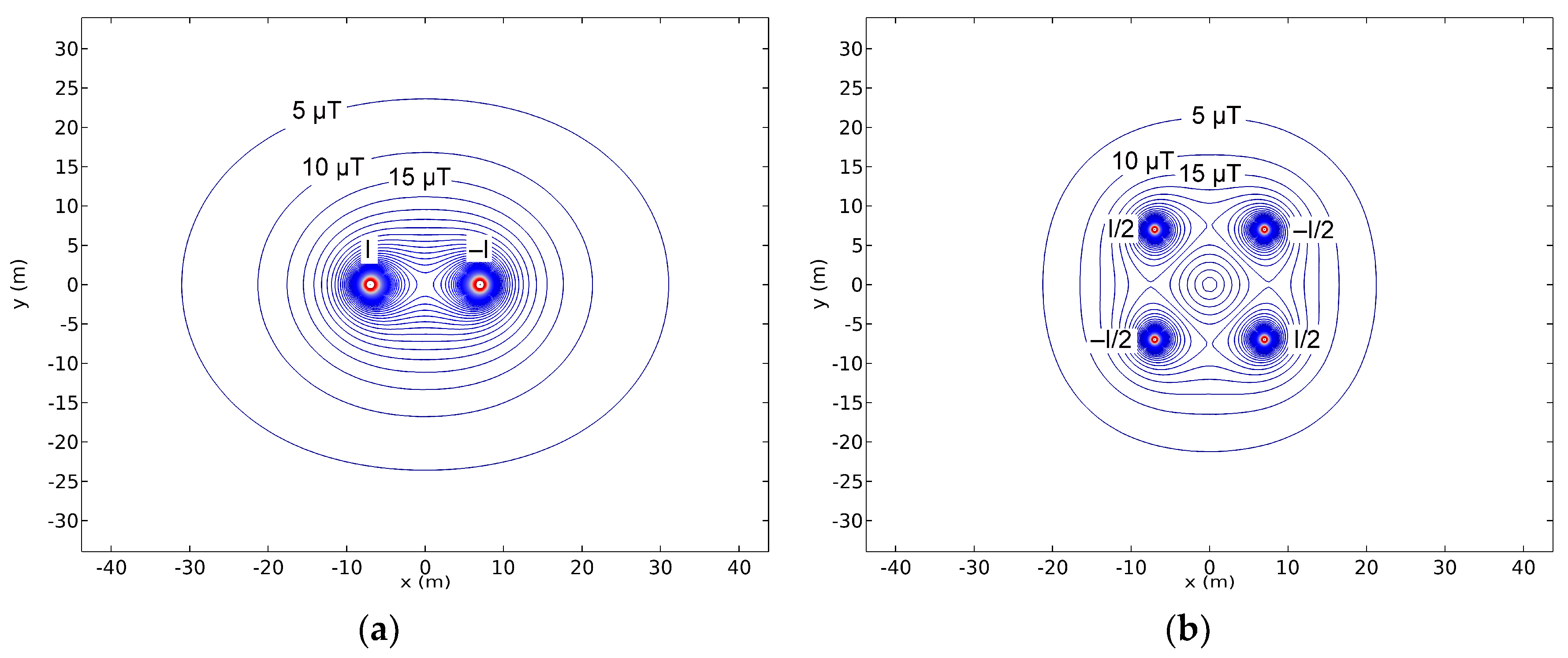
Figure 4.
MF levels for a double circuit line in two phase arrangements, (a) super-bundle and (b) low reactance line (based on [13], CIGRÉ 2009).
Figure 4.
MF levels for a double circuit line in two phase arrangements, (a) super-bundle and (b) low reactance line (based on [13], CIGRÉ 2009).
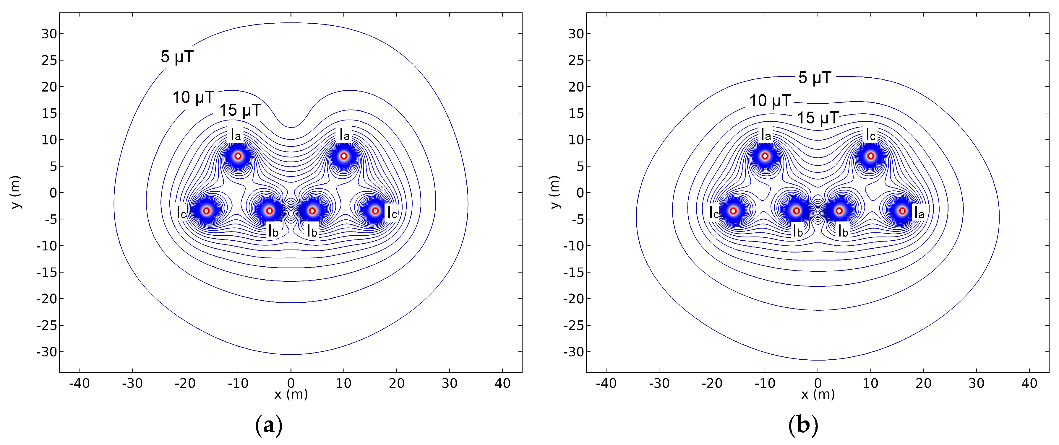
Figure 5.
Passive and active techniques as follows: (a) Passive loop, (b) conductive shield, (c) ferromagnetic shield, and (d) active loop.
Figure 5.
Passive and active techniques as follows: (a) Passive loop, (b) conductive shield, (c) ferromagnetic shield, and (d) active loop.


Figure 6.
MF before and after mixing phases on the LV connections in a MV/LV substation (based on [13], CIGRÉ 2009).
Figure 6.
MF before and after mixing phases on the LV connections in a MV/LV substation (based on [13], CIGRÉ 2009).

Figure 7.
Two examples of passive loops arrangements, as follows: (a) Independent series-compensated loops and (b) enchained series-compensated loops over a power line.
Figure 7.
Two examples of passive loops arrangements, as follows: (a) Independent series-compensated loops and (b) enchained series-compensated loops over a power line.

Figure 8.
Some parameters and constraints involved in the design of (a) passive loops in OHL and (b) enchained loops for an UPC.
Figure 8.
Some parameters and constraints involved in the design of (a) passive loops in OHL and (b) enchained loops for an UPC.

Figure 9.
Optimal location for the active loops and RF (color bar) achieved in the center of the target volume outside a MV/LV substation.
Figure 9.
Optimal location for the active loops and RF (color bar) achieved in the center of the target volume outside a MV/LV substation.

Figure 10.
Temperature distribution in shielded cable duct bank.


Table 1.
Reference values for both general public and occupational exposure (μT) at 50/60 Hz.
| Scope | ICNIRP 2010 [7] | IEEE 2002 [8] |
|---|---|---|
| General public | 200 | 904 |
| Occupational | 1000 | 2710 |
Table 2.
A timeline of applications for MF mitigation and related optimization techniques.
| MF Mitigation Method | Years | Optimization Technique | MF Mitigation Applications | ||
|---|---|---|---|---|---|
| 1990s | 2000s | 2010s | |||
| Conductor arrangement | Parametric analysis | OHL/UPC | |||
| Multi-objective OPF | OHL | ||||
| Genetic Algorithm | OHL/UPC | ||||
| Particle Swarm Optimization | OHL | ||||
| Statistical approach | UPC | ||||
| Differential Evolution | OHL | ||||
| Passive loops | Parametric Analysis | OHL/UPC/Subst. | |||
| Augmented Lagrangian | OHL | ||||
| Genetic Algorithm | OHL/UPC | ||||
| Particle Swarm Optimization | OHL | ||||
| Active loops | Parametric analysis | OHL/UPC/Subst. | |||
| Annealing optimization | OHL | ||||
| Genetic Algorithm | OHL/UPC/Subst. | ||||
| Multiagent Swarm Stochastic | OHL | ||||
| Passive shields | Parametric analysis | OHL/UPC/Subst. | |||
| Continuum Gradient | UPC | ||||
| Genetic Algorithm | UPC | ||||
© 2019 by the authors. Licensee MDPI, Basel, Switzerland. This article is an open access article distributed under the terms and conditions of the Creative Commons Attribution (CC BY) license (http://creativecommons.org/licenses/by/4.0/).
Share and Cite
MDPI and ACS Style
Bravo-Rodríguez, J.C.; del-Pino-López, J.C.; Cruz-Romero, P. A Survey on Optimization Techniques Applied to Magnetic Field Mitigation in Power Systems. Energies 2019, 12, 1332. https://doi.org/10.3390/en12071332
AMA Style
Bravo-Rodríguez JC, del-Pino-López JC, Cruz-Romero P. A Survey on Optimization Techniques Applied to Magnetic Field Mitigation in Power Systems. Energies. 2019; 12(7):1332. https://doi.org/10.3390/en12071332
Chicago/Turabian StyleBravo-Rodríguez, Juan Carlos, Juan Carlos del-Pino-López, and Pedro Cruz-Romero. 2019. "A Survey on Optimization Techniques Applied to Magnetic Field Mitigation in Power Systems" Energies 12, no. 7: 1332. https://doi.org/10.3390/en12071332
Note that from the first issue of 2016, this journal uses article numbers instead of page numbers. See further details here.