Experimental Study on Fast and Energy-Efficient Direct Driven Hydraulic Actuator Unit


1
Department of Mechanical Engineering, Aalto University, 02150 Espoo, Finland
2
Fiellberg Oy, FI-01720 Vantaa, Finland
*
Author to whom correspondence should be addressed.
Energies 2019, 12(8), 1538; https://doi.org/10.3390/en12081538
Submission received: 26 March 2019
/
Revised: 13 April 2019
/
Accepted: 18 April 2019
/
Published: 24 April 2019
(This article belongs to the Special Issue Energy Efficiency and Controllability of Fluid Power Systems 2018)
Abstract
:In this experimental study, a Direct Driven Hydraulics (DDH) system of the closed circuit type was utilized for cyclic vertical actuation in heavy load material handling. The actuator was controlled by a speed-controlled fixed displacement pump. The high energy saving potential of this system has been demonstrated in previous studies by the authors, but the dynamic characteristics of the ramped and P-controlled base system were considered unsatisfactory. Therefore, the system was implemented with an open-loop S-curve control that utilized a pre-calculated RPM (revolutions per minute) profile for the electric motor in order to realize a smooth actuator and load transition as a function of time. The results indicate that S-curve control is exceptionally well suited for producing a controlled lifting–lowering rapid motion with a heavy load, while still keeping the actuator chamber pressures within acceptable limits. In comparison, the motion produced by P-control was characterized by large unwanted pressure peaks together with velocity fluctuations and vibrations at the end of the stroke. Using a combination of S-curve control and hydraulic load compensation, a mass of 1325 kg could be moved 0.26 m in less than 0.5 s. The load compensation reduced the energy consumption by 64%, which would allow downsizing the electric motor and enable cost-efficient DDH implementation.
1. Introduction
Over the last two decades, the global demand for reducing the energy consumption and pollution emissions of machines has been the driving force for the university researchers and machine manufacturers alike to search for new solutions for the various sub-systems of machines in order to raise their energy efficiency and productivity. In the field of fluid power systems, this has led to the idea of replacing large central hydraulic systems encompassing several parallel connected valve-controlled actuators with a set of function-specific, independent, and pump-controlled single-actuator units. Doing so will reduce the hydraulic power losses of the hydraulic entirety and provide accurate matching of the supply of pressure and flow rate to the demands of the independent actuators. Another idea is to disconnect the direct connection between the prime mover and the actuators by using hydraulic accumulators and pressure transformers, thus enabling the prime mover to run at its most energy-efficient operation point, regardless of the status of the actuators. The proposed new solutions also enable regenerating hydraulic energy during the lowering of loads or during braking. The description of this trend and the associated new fluid power technology can be found in numerous studies. For example, [1] reviewed the approach of direct pump control, [2,3] reviewed solutions that minimize energy loss and utilize regeneration to improve the efficiency of the system, and [4,5] described the implementation of displacement-controlled actuators in work machines. In the following paragraphs, a more comprehensive introduction follows, explaining the background of the current study.
Hydraulically operated industrial applications are generally implemented as open circuit valve-controlled central hydraulic systems, where a fixed-speed electric motor-driven single pump or a pump group draws fluid from a large reservoir and feeds it to the system, where it is divided between the system’s actuators in relation to their need. If the system’s work cycle is repetitive and no requirements are set for the velocities of the actuators, even the simplest possible system structure with fixed displacement pumps and on/off-type directional control valves for actuators can yield quite good efficiency at moderate component costs. However, the situation considering the system’s efficiency and operating costs in this case changes drastically if the work cycle varies and/or the changing velocity or force requirements are set for the actuators during the system’s operation. This is because the division of the pump-produced fixed flow between the actuators must then be realized by inducing appropriate pressure losses in each actuator line, which is typically done with proportional directional control valves. If the flow rate and pressure requirements of the actuators differ greatly from each other during the work cycle, the pressure losses at some actuator lines will be very high, resulting in high power losses and low system efficiency. In addition, if all of the pump-produced flow is not consumed by the actuators, the excess flow has to be directed back to the reservoir through a pressure relief valve, which means that the system pressure has to rise above the cracking pressure of this valve, and as a consequence, the pressure losses in the actuator lines also have to rise to maintain the required flow division between actuators. The high-pressure losses in the system lead to high operating costs and typically a need for effective cooling in the system.
These efficiency-related problematics are typically partly solved by replacing the fixed displacement pumps with variable displacement pumps equipped with appropriate controllers. In these cases, the pump produces only the flow rate that is required by the actuators at each moment of the work cycle, and therefore, no flow is directed to the reservoir through the pressure relief valve. In consequence, the pressure level of the system, and likewise the pressure losses at the actuator lines, remain at a lower level, and the operating power of the pump does not rise as high as it would with fixed displacement pumps. However, because of the common pump or pumps and the feed line for the actuators, the pressure losses at the actuator lines are still required to maintain the required flow division between the actuators and match the pump-produced power with the actuator-consumed power. In addition, when the combined flow need of the actuators is low, the pump or pumps will turn to partial displacement, which leads to diminished efficiency of the pump. Despite these deficiencies, the pump-controlled systems typically have higher system efficiencies than valve-controlled systems, but their dynamics are typically lower. This is because the moving mass of a valve spool is only a fraction of the moving masses of a variable displacement pump in relation to the control forces. This dynamic deficiency is commonly compensated for by placing a pressure accumulator in parallel with the pump in the system, which commonly also has a positive effect on the system efficiency.
Since the mediocre or even low efficiency of central hydraulic systems is due to the principle of controlling parallel connected actuators with intentionally induced pressure losses, the obvious solution to improve efficiencies is to implement a control method that is not based on pressure losses and that enables the accurate matching of pump-produced power with actuator-required power. This can be achieved, e.g., by replacing the proportional directional control valves with converter units consisting of a variable displacement hydraulic motor and pump, but this will result in a complicated and expensive system. A more simple method is to separate all the system’s actuators into independent units with their own power sources, in which case the operating parameters, flow rate, and pressure level, as well as the component sizes for each actuator function, can be set and optimized individually, regardless of the requirements of the other actuators or functions. Furthermore, if the open circuit valve control is replaced with a closed-circuit pump control, the pressure losses in the system are restricted to the losses of the pipelines; and since this change simultaneously means a decreased fluid volume of the system, it leads to a diminished environmental hazard in case of oil leaks. In addition, a certain amount of redundancy is introduced in the system—should one actuator fail, the others are still operable to at least partially fulfil the functions of the machine. Finally, the closed circuit design makes it possible to recuperate energy during breaking and store it in electric form, e.g., in capacitors.
The downside of this solution is that every actuator requires a pump of its own, as well as an electric motor to run it, plus valves for fulfilling certain functions, all of which increase the system acquisition costs compared to a central hydraulic system. However, in an original single-actuator system, the total acquisition costs of a pump-controlled system may remain in the same magnitude as those of a valve-controlled system, depending on the system’s implementation. Such implementation can take the form of a fixed-speed electric motor with a variable displacement pump, a variable speed electric motor with a fixed displacement pump, or a variable speed electric motor with a variable displacement pump.
As stated above, from the dynamics point of view, the valve-controlled systems have traditionally been superior to pump-controlled systems; therefore, if low response times have been the priority in a system’s performance, the valve-controlled systems have been the only implementation option. The status between these two system types considering dynamic properties is currently changing because of the evolution of electric motors (servomotors) and their controllers (frequency converters and drives), which enables the motor to reach high dynamic speed, torque, and power control. Therefore, it is nowadays possible to design high-dynamic pump-controlled actuator systems, even if fixed displacement pumps are utilized instead of variable displacement pumps.
In recent years, several researchers have published work comparing closed-circuit displacement-controlled and valve-controlled single-actuator systems, in some cases including electro-mechanical actuators in the comparisons [6,7,8,9,10,11]. The researchers have found pump systems based on speed-control or a combination of speed control and displacement control to reach equal, or even superior, performance when considering the aspects of energy efficiency and dynamics. The published work include both theoretical, e.g., [12,13,14], and applied studies, e.g., [15,16,17]. In addition to the aforementioned benefits, several studies have also demonstrated that the noise level and the temperature rise of the pump-controlled closed-circuit systems are lower than those of other system types.
However, the application of pump-controlled single-actuator systems is not always easy and straightforward. Two typical difficulties are related to how to produce stable piston velocity, either when using differential cylinders, or when the actuator work cycle involves several operation point transitions. Frequent operation point changes may cause substantial reduction of energy efficiency, when the speed-displacement controller of the pump has been devised only for static operation. In order to overcome the difficulties, various new controllers and control concepts [18,19,20], or the use of an asymmetric pump (with flows matched to the displacement areas of the actuator piston) have been proposed [21,22]. One problematic that should also be considered when using a speed-controlled pump is the pump’s characteristics at low running speeds, which is studied in, e.g., [23].
This study presents the measurement results of a pump-controlled single-actuator system implemented with a fixed displacement pump and a speed-controlled servomotor; the principle is called Direct Driven Hydraulics (DDH). The system is applied in a full-scale test rig that emulates a real industrial application, a material-handling machine, which consecutively vertically lifts and lowers a fixed mass of 1325 kg over a transition range of 260 mm at high velocity. Previous stages of this study [24,25,26,27] manifested the high energy efficiency of the system, but the dynamic performance was considered unsatisfactory when using a traditional P-controller (in which the position of the cylinder is only controlled by applying a correction proportional to the difference between the desired position and the measured position when producing the speed command for the servomotor). The shortcomings appeared in the form of strong pressure fluctuations during movements and marked vibrations at the end of the actuator strokes. In this study, a new self-programmed S-curve controller is applied to the DDH system. The DDH system is tested with and without an external passive load compensation (LC) circuit for comparison purposes.
2. Methods
The DDH system with its different control methods was tested in a full-scale test rig that modeled a real industrial application, where a mass of 1325 kg was continuously lifted and lowered between two accurate vertical positions, the distance being 260 mm. In this research, the transition time between these positions (rise time for short) was varied in order to study the impact on energy consumption and how the quality of motion was affected by shortening the rise time. In the target application, the rise time should ultimately take place in 0.5 s.
The test rig was fitted with an external hydraulic load compensation system, which enabled adjusting the level of compensation, and also embodied the possibility of dampening the movement of the load, although this was not applied in the tests of this study.
The reason for testing the suitability of the DDH system for this specific application is that the currently used valve-controlled system, although satisfying the dynamic requirements, is considered to be too energy consuming. Prior studies [25,26,27] conducted with this test rig proved that the DDH system enables achieving a 53–87% reduction in energy consumption compared to a valve-controlled system. The magnitude of reduction depended on applying or not applying load compensation. The higher energy savings were achieved by using load compensation, even though this simultaneously meant that the system wasn’t capable of regenerating potential energy during load-lowering phases.
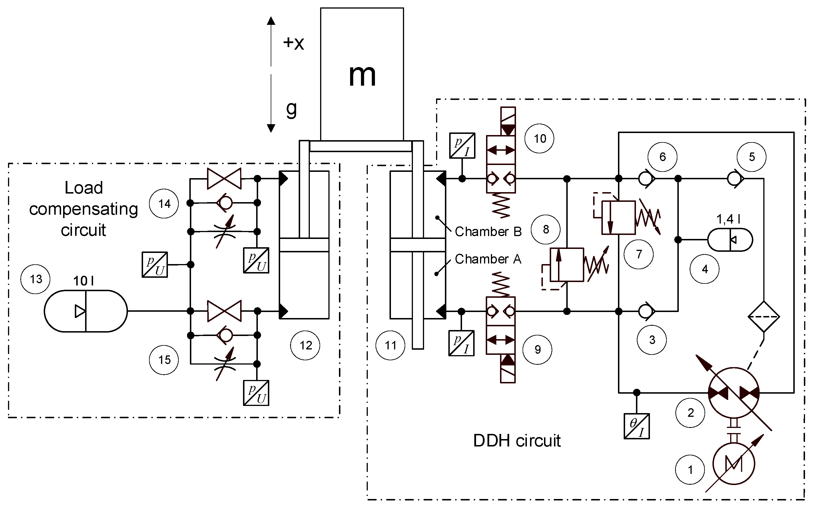
Figure 1 presents the test rig, and Figure 2 presents the circuit diagrams of the studied DDH system and the external load compensation and damping system. The main components of the actuating DDH circuit (on the right in Figure 2) are a permanent magnet synchronous motor (1), a swashplate pump (2), and a 50/36-sized actuating symmetric cylinder (11). All of the fluid power components of the DDH system are mounted either inside or on the surface of a single manifold (see Figure 1). Information on the components of the DDH and load-damping circuits is presented in Table 1, and further information on the design process of the DDH circuit and the industrial case, which the test rig is modeled, is presented in [24].
On the DDH circuit side, the measured quantities were actuator chamber pressures, the actuator position, and fluid temperature. In addition to these, the rotational velocity of the pump and the electrical motor’s mechanical output power were acquired from the IndraDrive system controlling the electric motor. All of the other quantities were calculated using this measurement data and component dimensions. Due to the short (<0.5 m) and relatively large (inner diameter 13 mm) pipelines and the large openings of the load-holding valves placed between the actuator and the pump, the pump port pressures were assumed to be the same as the corresponding actuator port pressures. On the load compensation circuit side, only the pressures at the compensator cylinder ports and accumulator were measured.
In the DDH circuit, the permanent magnet synchronous motor (1) runs the swashplate pump (2) either clockwise or counterclockwise depending whether the load (m) is to be lifted or lowered. Although the pump is of the variable displacement type, in these measurements, it was run in fixed displacement mode, and thus only the rotational velocity of the pump controlled the velocity of the symmetric DDH actuator (11). Solenoid-controlled valves (9, 10) are deployed if the load is to be held in place for a longer period of time, or if the control of the load is lost. Pressure relief valves (7, 8) are for cutting down possible pressure spikes. External leakage from the pump’s casing is fed back to the system via check valves (3, 5, 6). The pressure accumulator (4), whose 2-bar pre-charge pressure is selected according to the maximum allowed drain pressure of the pump (2), buffers the leakage flow and maintains constant ~2-bar pressure on the suction side of the pump, thus protecting it from cavitation.
In the load-compensating circuit, the differentially connected differential cylinder (12) acts against the gravitational force of the load, with the magnitude of compensation depending on the pressure that prevails in the accumulator (13). Full compensation of the load (1325 kg) is achieved at 127-bar pressure; however, during the lifting motion, the compensation pressure decreases slightly because of the volume increase in the compensation circuit. The damping option (14, 15) that enables restricting the outflows from the compensation cylinder chambers was inactive in the measurements conducted in this study.
In the measurements of the DDH system, two control methods were tested: position control with a P-controller (applying a correction proportional to the position error), and S-curve trajectory control with an additional PI (Proportional–Integral; applying an integral term to the position error, in addition to the proportional term) control for accurate final positioning. The results of previous tests conducted with P-control are described in [25,26,27]. Although the achieved energy savings with DDH in these tests with this controller were more than satisfactory compared to traditional valve-controlled implementation—even in the cases where load compensation wasn’t applied—the dynamic performance of DDH with the P-controller was unsatisfactory. The shortcomings of using the P-controller manifested themselves as vigorous pressure fluctuations during both upward and downward motions and marked position vibrations at the end of these motions.
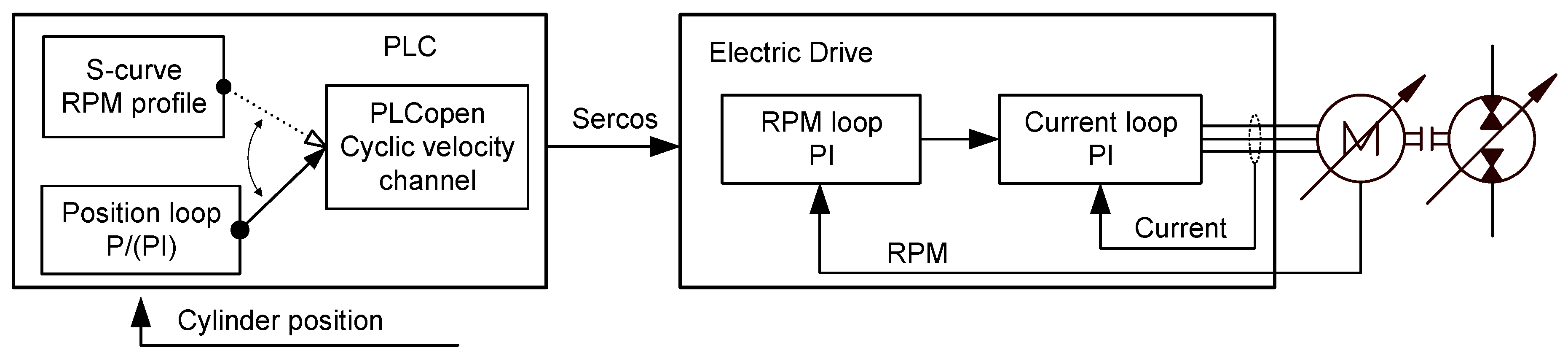
Figure 3 depicts the overall control system and its three stages: the typical PI controllers for the current and rotational velocity of the electric motor, which are incorporated in the electric drive, and cylinder position control, which is calculated in the PLC (Programmable Logic Controller). Although Figure 3 shows a variable displacement pump/motor, in this study, it was run in fixed displacement mode: 45 cm3/r for the load-compensated cases, and 21 cm3/r for the uncompensated cases. The data between PLC and electric drive (IndraDrive) is transmitted via Sercos bus.
The tests utilized two different controllers: a P-controller and an S-controller. The former is a simple PID (Proportional–Integral–Derivative) controller with only proportional gain, which utilizes position feedback from the cylinder and generates an RPM command for the electric drive based on the tracking error. This controller was designed in Simulink, from which it was transferred to the PLC using code generation. Earlier measurements indicated that a stepwise reference change produced large oscillations, and hence a rate limiter was added to create a steep ramp for the position reference signal.
The S-controller utilizes a pre-calculated bell-shaped RPM profile that produces an S-shaped position trajectory. The values for the speed of rotation (RPM profile, or command values for the drive) are calculated by integrating constant jerk (the time-derivative of acceleration) values two times with respect to time to give a velocity profile. When the velocity profile has been determined, one more integration gives the target position trajectory, which is a sigmoid-type curve. In this application, the actuator stroke motion is divided into five sections of acceleration (increasing, constant positive, decreasing, constant negative, and increasing), with corresponding jerk values (+ j, zero, - j, zero, +j). Here, the jerk value j is so selected that the position trajectory ends in the desired position.
The required flow rate is calculated by multiplying the values of the velocity profile with the displacement area of the piston. Finally, the command values of speed of rotation are calculated by dividing the flow rate values by the displacement of the pump. These RPM values are stored in an array from which one value is read at each time step when performing the motion. The RPM values are used as input in a function block (ML_WriteCyclicVelocity) for cyclically writing velocity commands to the drive.
The S-controller works in an open-loop configuration and doesn’t utilize position feedback from the actuator. Changes in operating conditions affect the accuracy of the open-loop control, and hence a PI controller is used to decrease the positioning error after each RPM profile in order to prevent drifting over time. The algorithm that generates the RPM profile is based on [28]. Both controllers operate on a 2-ms loop time due to the limited CPU (Central Processing Unit) power in the PLC. The typical trajectories produced with the controllers are illustrated in Figure 4.
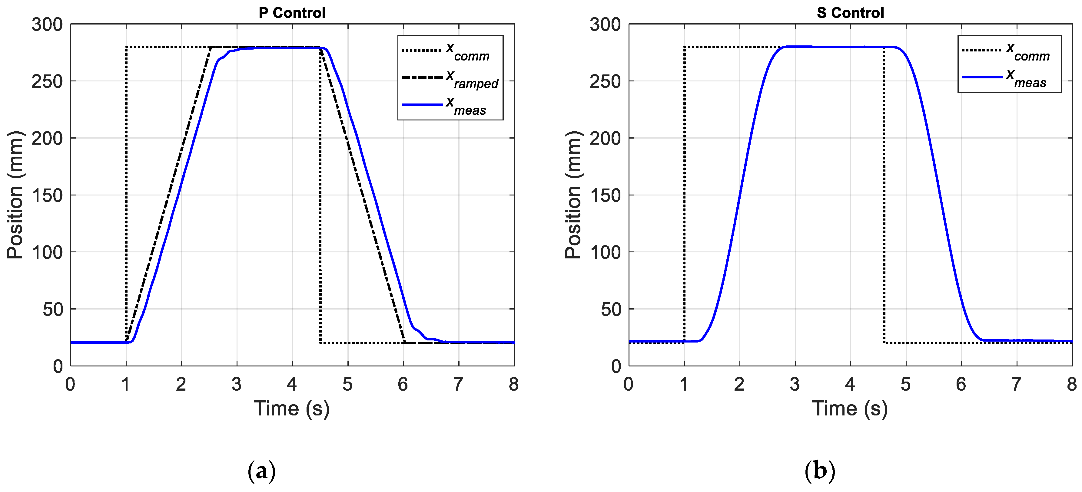
During measurements, the load mass was continuously lifted and lowered using a motion cycle that was composed of a rapid lift—using either a ramp or trajectory—followed by a short standstill in the upper position before lowering the mass back to its starting position using the same ramp or trajectory as with lifting, as shown in Figure 4. The cycle was repeated after another standstill in the lower position, and each measurement run consisted of several cycles. The starting position of the cycle was 20 mm from the actuator’s retracted position, and the end position corresponded to an extension of 280 mm, resulting in the targeted 260 mm stroke.
The measurements were conducted with two controllers, with and without load compensation. The target in the measurement was to find the shortest possible rise time with the satisfactory behavior of system quantities whilst not exceeding the 160-bar system pressure. The measurements conducted for this study are presented in Table 2.
In the uncompensated cases, rise times shorter than 2.0 s were not possible without exceeding the set maximum system pressure of 160 bar. The results of the measurements are presented in Chapter 3 and discussed in Chapter 4.
3. Results
The results of the measurement program are presented in the figures and tables of this section. For each targeted rise time, the results of using P-control versus S-curve control are shown in terms of the quality of the produced motion, the actuator chamber pressures, and the power and energy consumption.
For the test cases to be compared, the aim was to produce lifting and lowering times that were as equal as possible. However, there were slight differences in the actual rise times (time to produce 98% of the stroke), as shown in Table 3. In all of the test cases, it was possible to achieve actual rise times that were less than the targeted values, and when S-curve control was used, the actual rise times were less than what was achieved with P-control.
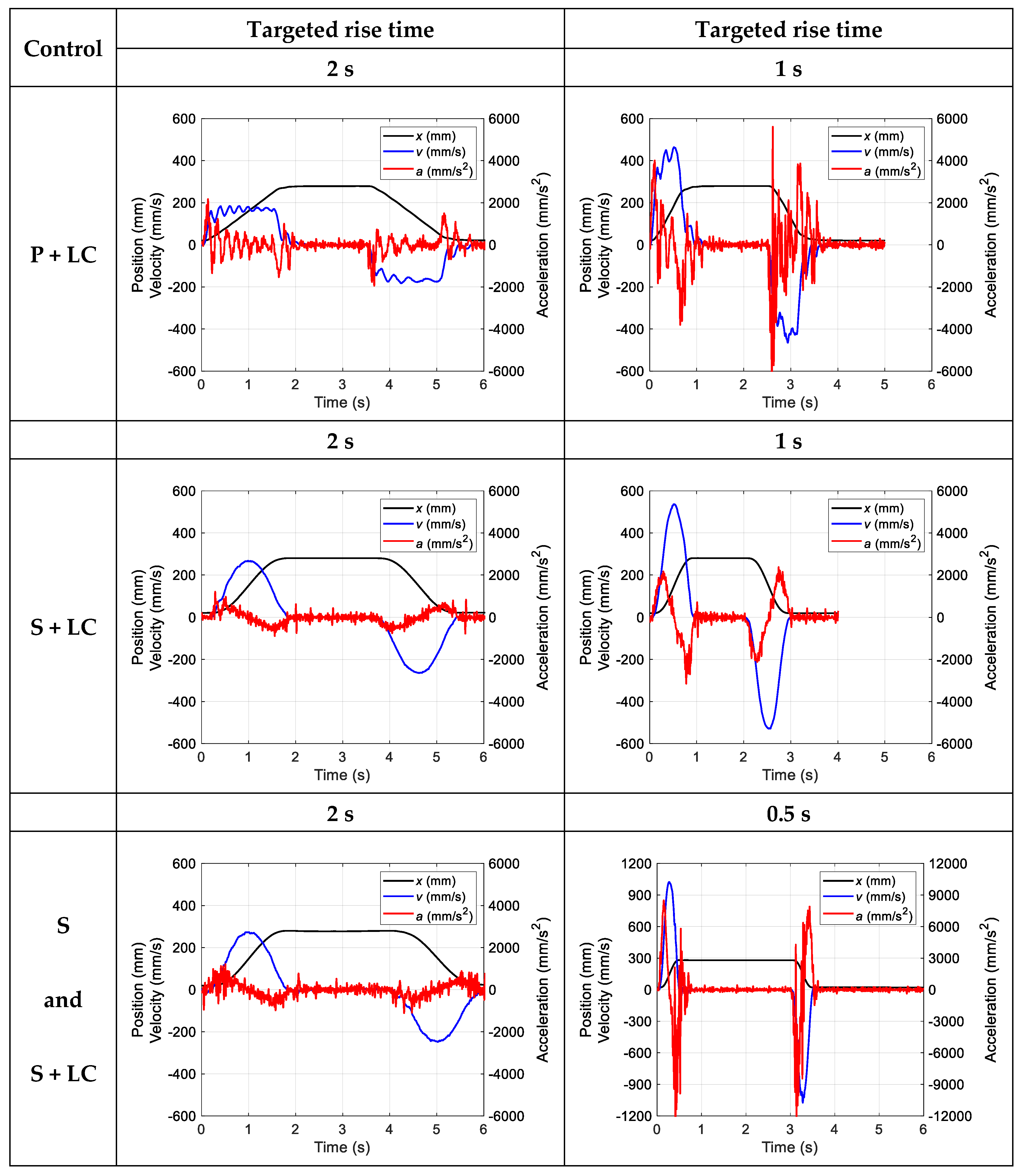
Figure 5 shows the position, velocity, and acceleration of the actuator piston rod with P-control and S-curve control and for different rise times measured during one motion cycle (see also Figure 4). The velocity and acceleration signals were derived from the position signal by differentiation in Matlab, after the data acquisition.
Note that the overall cycle times may vary between the tests. This is because slightly different holding times (when the actuator was in either the upper or the lower position) were used during testing; it was difficult to match the holding times a priori, because of different settling times with different controllers. As the rise times were the main target of this study, and as the power consumption during the motion cycle was totally dominated by the stroke phases, the impact of the holding time could be considered minor when the load compensated system was used. In the one uncompensated test case (S-curve control and 2 s targeted rise time), the holding time was between 0.4–0.7 s longer (in the upper position) and 0.2–0.5 s longer (in the lower position), compared to the 2-s rise time cases with load compensation. All in all, holding times of at least one second were used in all of the test cases, before the actuator piston was returned to the opposite holding position.
The two top rows of Figure 5 show that P-control causes fluctuations in velocity and acceleration during the stroke, whereas S-curve control produces clean velocity curves, and there is less fluctuation in the acceleration curves.
Figure 6 demonstrates the chamber pressures of the actuator cylinder and the load-compensating cylinder for the different control solutions and the different target rise times. In the load-compensated cases, P-control causes frequent pressure pulsations with much higher peak pressure values than are present in the pressure graphs of the cases utilizing S-curve control. In the uncompensated case, the pressure in the lifting chamber (the A chamber) of the actuator cylinder varied approximately between 120–160 bar during the whole cycle, whereas the pressure in the opposite actuator chamber (the B chamber) remained zero. Note also that in the uncompensated case, the load compensation pressure is zero by definition.
The only uncompensated case that could be run was the one having approximately a 2-s rise time and only utilizing S-curve control. This was because the actuator cylinder was only rated for a maximum pressure of 160 bar. This highest permissible pressure level was reached even with shorter strokes when utilizing P-control, and with P-control and a 1-s rise time, the actuator chamber pressures in excess of 200 bar could be reached cf., e.g., ([26], Figure 4). Therefore, P-control was dropped as an alternative when studying the uncompensated case.
Figure 7 illustrates the power consumption in the DDH unit. PMotor is the electrical motor’s mechanical output power (i.e., the input power to the hydraulic pump/motor), and PActuator is the power produced by the net hydraulic force in the actuator cylinder (pressure drop over the piston multiplied by the pressurized piston area and the velocity of the piston). The electrical motor’s mechanical output power was recorded by parameter S-0-0385 of the IndraDrive system [29].
In the beginning of the stroke, power is needed to accelerate the load; this power pulse (or these pulses when using P-control) is approximately four to five times higher when the targeted rise time was 1 s, in comparison to when the rise time was 2 s. Removing the load compensation also caused the required power to increase multiple times (cf. cases with S-curve control, 2-s rise time, with and without load compensation in Figure 7).
The energy consumption during one lifting–lowering cycle is shown for the different cases of control and target rise time in Table 4. EMotor and EActuator stand for the values of PMotor and PActuator, respectively, integrated over one motion cycle. During braking, and for the uncompensated case during lowering, energy could be regenerated. Unfortunately, electric power and energy values were not reliably recorded during the tests (a problem that was encountered after updating the control software), and the actual regeneration remained unknown. Nevertheless, the electric drive has the ability to store energy in the capacitors connected to its DC (Direct Current) bus, and therefore, the energy values included in Table 4 include regeneration. If no losses were present and if all the potential energy could be regenerated, the closed-loop integrals should be zero. Thus, the departures from zero in Table 4 are an indication of the losses in the system.
As an example of the energy consumption during the different phases of the motion cycle, energy consumption during lifting, holding in the upper position, lowering, and holding in the lower position are given in Table 5 for the 1-s and 0.5-s nominal rise time cases presented in Table 4. Negative energy consumption values are the result of the regeneration associated with braking or lowering the load. When the load compensation circuit is active, most of the energy needed to lift the load comes from the gas spring of the hydraulic accumulator, as reflected in the values of ELCH. In the tabulated cases, the total hydraulic energy (EActuator + ELCH) amounts to 3.58 kJ, 3.61 kJ, and 3.97 kJ, respectively. This can be compared to the increase in potential energy involved in lifting the load 260 mm, which is 3.38 kJ.
4. Discussion
In this study, the performance characteristics and operating properties of a pump speed-controlled DDH system were experimentally evaluated utilizing two different motion controllers: a P-controller and an S-controller. The test setup emulates an industrial material-handling machine that cyclically and rapidly lifts and lowers a mass of 1325 kg over a range of 0.26 m.
With the P-controller, it has previously been possible to achieve a rise time of approximately one second [26,27]. In these tests, as well as in the tests of the current study, the P-controller’s task was facilitated by using a rate limiter, which replaced the step-wise change in the position reference with a steep ramp. Nevertheless, the motion was plagued with pronounced vibrations toward the end of the stroke.
In addition, the motion was plagued with a series of pressure spikes causing unwanted fluctuations in the linear velocity of the actuator piston during the stroke. In tests where load compensation was not used, the pressure spikes in the lifting chamber of the actuator cylinder could exceed 200 bar [26,27]. The problems with motion vibrations and high chamber pressures became even more pronounced when the rise time was shortened below one second. Therefore, to avoid these problems arising as a result of using the P-controller in combination with closed-loop hydraulics, it was decided to implement an alternative controller.
The S-controller utilizes a pre-calculated RPM profile for the electric motor such that the position of the actuator piston traces a smooth S-shaped curve when plotted against time. Position feedback is not used by this controller during the stroke, which reduces the propensity for pressure fluctuations during the stroke (cf. two first rows of Figure 6 which compare the P-controller and S-controller, when used with load compensation). With the S-controller, at the ends of the stroke, the position control is handed over to a PI controller for the duration of the holding phase. This solves the problem that the accuracy of the open-loop implementation depends on the operating conditions (especially temperature), and it also keeps the position from drifting during holding.
It was only through utilizing the S-controller with load compensation that enabled achieving the targeted ultimate rise time of 0.5 s (the actual lifting and lowering times were 0.44 s and 0.45 s, respectively). The results for this test case, which are shown in Figure 5, Figure 6 and Figure 7, under the heading 0.5 s, represent the best performance achieved with the test setup. A rise time of 0.5 s or less also appears to be unique among the studies published about the performance of electro-hydraulic actuators, due to the combination of very high load and fast response time. The maximum velocity was 1.02 m/s during the lifting, and 1.07 m/s during the lowering. Despite the very short rise times, the chamber pressures in the actuator were still acceptable (the pressure peaks only reached the 160-bar limit). However, the power peaks were high. For example, the mechanical power needed from the electric motor during lifting was now 2.9 times higher compared to the case featuring double the rise time (Figure 7, S-curve control, rise times 0.5 s versus 1 s). The maximum momentary flow rate in this case (0.5-s lifting time) amounted to approximately 60 L/min. The maximum flow rates when using S-control were proportional to the lifting times, such that for a 1-s lifting time, the value was 30 L/min; and for a 2-s lifting time, the value was 15 L/min. Flow rates were calculated as the product of the actuator piston velocity (determined by differentiation of the measured position signal) and piston displacement area.
When no load compensation was used, it was only by utilizing the S-controller that it was possible to perform the required stroke within a reasonable rise time. Even then, the rise time had to be restricted to 2 s; otherwise, the rated pressure of the actuator would have been exceeded. In order to decrease the lifting time and keep the pressure in the lifting chamber of the actuator within acceptable limits, a larger actuator cylinder would have to be installed if load compensation was not used.
Energy consumption values for one lifting–lowering cycle for the different test cases are given in Table 4. When the targeted rise time was 2 s and the load compensation circuit was active, there was no difference in energy consumption between the S and P-controllers (the mechanical output energy from the electric motor being 0.80 kJ in both cases). However, when the targeted rise time was decreased to 1 s, the energy drawn from the electric motor increased to 1.67 kJ with P-control, while with S-control, only a small overall increase (to 0.85 kJ) was observed. The reason was that with S-control, a much higher amount of energy could be recuperated via breaking than when using P-control (cf. 1 s cases in Figure 7). When the targeted rise time was further decreased to 0.5 s (which was only possible with the S-controller), the amount of mechanical energy needed from the electric motor increased markedly (to 2.45 kJ). Table 4 also indicates the benefit of load compensation (S-control and a 2-s targeted rise time). When load compensation was activated, the cyclic energy consumption (energy input needed from the electric motor) was reduced by 64% ((2.21–0.80) kJ/2.21 kJ = 0.64).
Table 5 shows (for S and P-controls with load compensation and 1-s and 0.5-s rise times) a breakdown of the energy consumption values for the different phases of the motion cycle. Focusing just on lifting, one can see that using P-control demanded 44% more energy from the motor than S-control ((1.02–0.71) kJ/0.71 kJ = 0.44). On the other hand, for S-control, decreasing the target rise time from 1 s to 0.5 s (actual lifting times 0.83 s and 0.44 s) increased the energy needed from the motor by 113% ((1.51–0.71) kJ/0.71 kJ = 1.13).
It can also be seen that thanks to load compensation, most of the energy needed to move the load originates from the gas spring of the hydraulic accumulator. During lifting, the hydraulic energy obtained from the load compensation circuit (ELCH) ranged from 3.12 kJ to 3.16 kJ, which can be compared to the increase in potential energy due to lifting the load 260 mm, which was 3.38 kJ.
As shown in Figure 7, in the different tests, the peak mechanical power required from the electric motor ranged from 0.7 kW (S + LC control and 2-s targeted rise time) to 14.8 kW (S + LC control and 0.5-s targeted rise time). Without load compensation, the fastest rise time with the current test setup was 2 s. In this case, the peak mechanical power from the electric motor was 5.1 kW. Figure 7 also shows that substantial amounts of energy can be regenerated (negative power values) during braking and lowering the load.
When the energy consumption results gained with DDH systems using different controls are compared with the simulated results of the traditional valve-controlled system (see [26,27]), it is revealed that the DDH principle enables more than halving the system energy consumption, even when no load compensation is implemented. The load compensation naturally enables reaching much lower energy consumption, since the load to be shifted is smaller. When considering the dynamic behavior of the valve-controlled system, no major problems were encountered in simulations (see [25]), the only exception being marked pressure pulsation in the load-opposing actuator chamber when the movement is stopped.
So far, only relatively short tests have been conducted with the test rig. In order to assess the reliability of the DDH concept, long-term testing should be conducted. Such testing should involve, in addition to monitoring the mechanical performance of the pump and the actuator, monitoring the development of the oil temperature and the temperature of the electric motor. This will indicate the need for possible additional cooling. Currently, the electric motor and the electric drive cabinet are equipped with cooling fans, but the DDH hydraulics do not feature an oil cooler. In addition to the effects of altering the system temperature (changing viscosity), the effects of external disturbances, e.g., varying load and sensor noise, on the operation of the open-loop S-controlled system should be studied. Since S-curve control is based on a pre-calculated RPM profile, all the changes in the system (even component degradation) during its operation will presumably result in changes in system characteristics (accuracy and stability), unless their effects are not compensated for.
In addition, the effect of combining the S-curve approach with P-control could be explored in order to determine whether the pressure pulses and fluctuating velocity could be avoided (even if using P-control in a closed-loop hydraulic circuit), while at the same time avoiding the lack of accuracy pertaining to the open-loop control.
5. Conclusions
S-curve control appears to be exceptionally well suited for producing a controlled lifting–lowering motion with a heavy load rapidly, while still keeping the chamber pressures within acceptable limits. In fact, it was only when utilizing the S-controller that the rise time of 0.5 s could be achieved without exceeding the maximum rated pressure of the actuator cylinder (160 bar). In addition, thanks to the controlled acceleration and open-loop control during the stroke, the motion vibrations encountered with P-control were largely avoided with S-curve control.
Using hydraulic load compensation will reduce the cyclic energy consumption substantially: a reduction of 64% was measured in this study, even when comparing actuation cases with the advantageous S-control with and without load compensation, and for a work cycle involving a 2-s rise time. Additionally, load compensation will limit the need for high pressure in the DDH circuit as well as the peak power needed from the electric motor. Thus, a smaller electric motor and actuator can be used, and an expensive DDH implementation can be avoided.
Naturally, the load compensation principle could also be applied to traditional valve-controlled systems to reduce their power need, but even in a single-actuator system, the system efficiency would be lower compared to a DDH system because of the pressure loss (i.e., power loss) control principle of the valve-controlled systems. In addition, the lengths of conduits are typically much longer in valve-controlled systems compared to DDH systems (where the pipe lengths are minimized), which contributes to higher power losses (although they are small in absolute value) in valve-controlled systems.
Currently, the studies have involved only relatively short tests. In further studies, long-term testing, including determining the need for cooling, should be pursued in order to assess the reliability of the DDH concept for heavy load handling.
Author Contributions
Investigation and data curation, T.K, H.K., O.C.; writing—original draft preparation, T.K, H.K., O.C.; writing—review and editing, T.K, H.K., O.C.; funding acquisition, M.P. and T.M.
Funding
This research has received financial support of Business Finland (Finnish Funding Agency for Innovation), project EL-Zon, Academy of Finland, project IZIF, and Aalto University, Finland.
Acknowledgments
The help of Antti Sinkkonen is greatly appreciated.
Conflicts of Interest
The authors declare no conflict of interest.
Nomenclature
| a | Acceleration of actuator piston | m/s2 |
| EActuator | Hydraulic energy of actuator for one cycle | m/s2 |
| ELCH | Hydraulic energy of load compensator | kJ |
| EMotor | Mechanical output energy of electric servo motor for one cycle | kJ |
| Lower chamber pressure of actuator | Pa | |
| Upper chamber pressure of actuator | Pa | |
| Pressure of load compensator circuit | Pa | |
| PMotor | Mechanical output power of electric servo motor | W |
| PActuator | Hydraulic power of actuator | W |
| x | Position of actuator piston | m |
| xmeas | Measured position of actuator piston | m |
| xtrig | Triggering (reference) position for actuator piston | m |
| xramp | Ramped (reference) position for actuator piston | m |
| v | Velocity of actuator piston | m/s |
References
- Quan, Z.; Quan, L.; Zhang, J. Review of energy efficient direct pump controlled cylinder electro-hydraulic technology. Renew. Sustain. Energy Rev. 2014, 35, 336–346. [Google Scholar] [CrossRef]
- Rydberg, K.-E. Energy efficient hydraulics—System solutions for loss minimization. In Proceedings of the National Conference on Fluid Power, “Hydraulikdagar’15”, Linköping, Sweden, 16–17 March 2015. [Google Scholar]
- Rydberg, K.-E. Energy efficient hydraulic systems and regenerative capabilities. In Proceedings of the Ninth Scandinavian International Conference on Fluid Power, SICFP’05, Linköping, Sweden, 1–3 June 2005. [Google Scholar]
- Rahmfeld, R.; Ivantysynova, M. Displacement controlled linear actuator with differential cylinder—A way to save primary energy in mobile machines. In Proceedings of the 5th International Conference on Fluid Power Transmission and Control (ICFP’2001), Hangzhou, China, 3–5 April 2001. [Google Scholar]
- Rahmfeld, R.; Ivantysynova, M.; Weber, J. Displacement Controlled Wheel Loader—A simple and clever Solution. In Proceedings of the 4th International Fluid Power Conference, 4. IFK, Dresden, Germany, 24–26 March 2004; Volume 2, pp. 183–196. [Google Scholar]
- Michel, S.; Weber, J. Energy-efficient electrohydraulic compact drives for low power applications. In Proceedings of the Fluid Power and Motion Control FPMC 2012, Bath, UK, 12–14 September 2012; pp. 93–107, ISBN 978-0-86197-187-9. [Google Scholar]
- Boes, C.; Helbig, A. Electro hydrostatic actuators for industrial applications. In Proceedings of the 9th International Fluid Power Conference, 9. IFK, Aachen, Germany, 24–26 March 2014; Volume 2, pp. 134–142, ISBN 978-3-9816480-1-0. [Google Scholar]
- Helbig, A.; Boes, C. Electric hydrostatic actuation—Modular building blocks for industrial applications. In Proceedings of the 10th International Fluid Power Conference, 10. IFK, Dresden, Germany, 8–10 March 2016; pp. 93–102. [Google Scholar]
- Altare, G.; Vacca, A. A design solution for efficient and compact electro-hydraulic actuators. Procedia Eng. 2015, 106, 8–16. [Google Scholar] [CrossRef]
- Padovani, D.; Ketelsen, S.; Hagen, D.; Schmidt, L. A self-contained electro-hydraulic cylinder with passive load-holding capability. Energies 2019, 12, 292. [Google Scholar] [CrossRef]
- Niraula, A.; Zhang, S.; Minav, T.; Pietola, M. Effect of zonal hydraulics on energy consumption and boom structure of a micro-excavator. Energies 2018, 11, 2088. [Google Scholar] [CrossRef]
- Räcklebe, S.; Helduser, S. Electric hydrostatic drive—A concept for the clamping unit of a high-speed 245 injection moulding machine. In Proceedings of the Power Transmission and Motion Control PTMC 2007, Bath, UK, 12–14 September 2007; pp. 245–254, ISBN 978-0-86197-140-4. [Google Scholar]
- Tašner, T.; Les, K.; Tič, V.; Lovrec, D. Energy efficiency of different electrohydraulic drives. In Proceedings of the 9th International Fluid Power Conference, 9. IFK, Aachen, Germany, 24–26 March 2014; Volume 3, pp. 14–25, ISBN 978-3-9816480-2-7. [Google Scholar]
- Pietrzyk, T.; Roth, D.; Schmitz, K.; Jacobs, G. Design study of a high speed power unit for electro hydraulic actuators (EHA) in mobile applications. In Proceedings of the 11th International Fluid Power Conference, 11. IFK, Aachen, Germany, 19–21 March 2018; pp. 233–245. [Google Scholar]
- Müller, K.; Dorn, U. Variable Speed Drives—Customer benefits in injection molding machines and presses. In Proceedings of the 7th International Fluid Power Conference, 7. IFK, Aachen, Germany, 22–24 March 2010. [Google Scholar]
- Brahmer, B. CLDP—Hybrid drive using servo pump in closed loop. In Proceedings of the 8th International Fluid Power Conference, 8. IFK, Dresden, Germany, 26–28 March 2012. [Google Scholar]
- Siemer, E.; Boes, C.; Bolik, R. Electro-hydrostatic drive concept for the ring rolling process. In Proceedings of the 11th International Fluid Power Conference, 11. IFK, Aachen, Germany, 19–21 March 2018; pp. 144–153. [Google Scholar]
- Willkomm, J.; Wahler, M.; Weber, J. Model predictive control of speed-variable variable-displacement pumps to optimize energy efficiency. In Proceedings of the 9th International Fluid Power Conference, 9. IFK, Aachen, Germany, 24–26 March 2014; Volume 1, pp. 372–385, ISBN 978-3-9816480-0-3. [Google Scholar]
- Willkomm, J.; Wahler, M.; Weber, J. Potentials of speed and displacement variable pumps in hydraulic applications. In Proceedings of the 10th International Fluid Power Conference, 10. IFK, Dresden, Germany, 8–10 March 2016; pp. 379–391. [Google Scholar]
- Sun, Y.; Imam, A.; Wu, C.; Sepehri, N. Stability study of a pump-controlled circuit for single rod cylinders via the concept of Lyapunov exponents. In Proceedings of the ASME/BATH 2017 Symposium on Fluid Power and Motion Control FPMC 2017, Sarasota, FL, USA, 16–19 October 2017; ISBN 978-0-86197-187-9. [Google Scholar]
- Quan, L.; Ge, L.; Wang, B.C.; Li, B.; Zhao, B.; Lu, Z. Performance of speed variable asymmetric pump controlled asymmetric hydraulic cylinder. In Proceedings of the 10th JFPS International Symposium on Fluid Power 2017, Fukuoka, Japan, 24–27 October 2017. [Google Scholar]
- Ge, L.; Quan, L.; Zhang, X.; Huang, J.; Zhao, B. High energy efficiency driving of the hydraulic excavator boom with an asymmetric pump. In Proceedings of the 11th International Fluid Power Conference, 11. IFK, Aachen, Germany, 19–21 March 2018; pp. 347–357. [Google Scholar]
- Achten, P.; Potma, J.; Achten, J. Low speed performance of axial piston machines. In Proceedings of the BATH/AASME 2018 Symposium on Fluid Power and Motion Control FPMC 2018, Bath, UK, 12–14 September 2018. [Google Scholar]
- Hänninen, H.; Minav, T.; Pietola, M. Replacing a constant pressure valve controlled system with a pump controlled system. In Proceedings of the BATH/AASME 2016 Symposium on Fluid Power and Motion Control FPMC 2016, Bath, UK, 7–9 September 2016. [Google Scholar]
- Koitto, T.; Kauranne, H.; Calonius, O.; Minav, T.; Pietola, M. Experimental investigation of a directly driven hydraulic unit in an industrial application. In Proceedings of the 11th International Fluid Power Conference, 11. IFK, Aachen, Germany, 19–21 March 2018. [Google Scholar]
- Koitto, T.; Calonius, O.; Kauranne, H.; Minav, T.; Pietola, M. Enhanced energy efficiency of industrial application by direct driven hydraulic unit. In Proceedings of the 2018 IEEE Global Fluid Power Society PhD Symposium, GFPS2018, Samara, Russia, 18–20 July 2018. [Google Scholar]
- Kauranne, H.; Koitto, T.; Calonius, O.; Minav, T.; Pietola, M. Direct driven pump control of hydraulic cylinder for rapid vertical position control of heavy loads—Energy efficiency including effects of damping and load compensation. In Proceedings of the BATH/AASME 2018 Symposium on Fluid Power and Motion Control FPMC 2018, Bath, UK, 12–14 September 2018. [Google Scholar]
- Lambrechts, P. Advanced Setpoints for Motion Systems. MathWorks File Exchange, Version 1.2.0.1. September 2016. Available online: https://se.mathworks.com/matlabcentral/fileexchange/16352-advanced-setpoints-for-motion-systems (accessed on 25 March 2019).
- IndraDrive MPx-20 Functions, Application Manual, Edition 1, R911345608; Bosch Rexroth AG: Lohr am Main, Germany, 2017; pp. 1271, 1275–1276, 1279.
Figure 1.
Vertical motion test rig containing the DDH and load compensation systems.

Figure 2.
Two separate hydraulic systems of the test rig; actuating DDH circuit (right), and compensation and damping circuit (left).
Figure 2.
Two separate hydraulic systems of the test rig; actuating DDH circuit (right), and compensation and damping circuit (left).

Figure 3.
Control structure of the DDH system.

Figure 4.
Examples of lifting and lowering cycles used in measurements: (a) P-control and (b) S-control.
Figure 4.
Examples of lifting and lowering cycles used in measurements: (a) P-control and (b) S-control.

Figure 5.
Position, velocity, and acceleration of actuator piston rod with different controllers and rise times.
Figure 5.
Position, velocity, and acceleration of actuator piston rod with different controllers and rise times.

Figure 6.
Pressure in actuator chambers A and B, as well as pressure in load compensation (LC) circuit during one lift-lower cycle with different controllers and load compensation arrangements.
Figure 6.
Pressure in actuator chambers A and B, as well as pressure in load compensation (LC) circuit during one lift-lower cycle with different controllers and load compensation arrangements.

Figure 7.
Electric motor’s mechanical output power and the actuator’s hydraulic power together with the actuator position with different controllers, load compensation (LC) arrangements, and rise times.
Figure 7.
Electric motor’s mechanical output power and the actuator’s hydraulic power together with the actuator position with different controllers, load compensation (LC) arrangements, and rise times.


Table 1.
Fluid power components of the test rig.
| Nr | Type | Description | Details |
|---|---|---|---|
| DDH circuit | |||
| 1 | Electric motor | Permanent magnet synchronous motor | Bosch MSK101E-0300-NN |
| 2 | Pump/motor | Swashplate type, 45 cm3/rev max | Bosch A10VZG045EZ400 |
| 11 | Cylinder | Symmetrical type, 50/36-mm piston/piston rod 300-mm stroke length | Bosch CGM1F3/50/36/300A20 /F11CKUTS42580 |
| 4 | Accumulator | Bladder type, 1.4 l @ 2 bar | Bosch HAD1.4-250-1X |
| 3,5,6 | Check valve | Cracking pressure 0.3 bar | Sun Hydraulics CXEE-XAN |
| 7,8 | Pressure relief valve | Nominal opening pressure 160 bar | Bosch DBDS 10 K1X/200 |
| 9,10 | Load holding valve | Bosch VEI8A2T12 | |
| Load compensation circuit | |||
| 12 | Cylinder | Differential type, 50/36-mm piston/piston rod 300-mm stroke length | Bosch CDM1MP5/50/36/300A20 /B11CFUMWW |
| 13 | Accumulator | Bladder type, 10 L | Bosch HAB10-330-6X |
| 14,15 | Damping option | Parallel connected shut-off, check, and throttle valves |
Table 2.
Measurement program.
| System | Targeted Rise Time (s) | Control |
|---|---|---|
| Load compensated | 2.0 | P-control; S-curve |
| Load compensated | 1.0 | P-control; S-curve |
| Load compensated | 0.5 | S-curve |
| Uncompensated | 2.0 | S-curve |
Table 3.
Targeted nominal stroke times and actual stroke times.
| System | Control | Abbreviation | Targeted Rise Time (s) | Lifting (s) | Lowering (s) |
|---|---|---|---|---|---|
| Load compensated | P-control | P + LC | 2.0 | 1.830 | 1.880 |
| Load compensated | S-curve | S + LC | 2.0 | 1.650 | 1.690 |
| Load compensated | P-control | P + LC | 1.0 | 0.912 | 1.016 |
| Load compensated | S-curve | S + LC | 1.0 | 0.830 | 0.850 |
| Load compensated | S-curve | S + LC | 0.5 | 0.440 | 0.450 |
| Uncompensated | S-curve | S | 2.0 | 1.640 | 1.880 |
Table 4.
Mechanical energy output from the electric motor and hydraulic energy consumption in the actuator cylinder during one lifting–lowering cycle.
Table 4.
Mechanical energy output from the electric motor and hydraulic energy consumption in the actuator cylinder during one lifting–lowering cycle.
| Control | LC | Energy Consumption (kJ) | |||||
|---|---|---|---|---|---|---|---|
| Rise Time | |||||||
| 2 s | 1 s | 0.5 s | |||||
| EMotor | EActuator | EMotor | EActuator | EMotor | EActuator | ||
| P | on | 0.80 | 0.33 | 1.67 | 0.48 | - | - |
| S | on | 0.80 | 0.35 | 0.85 | 0.54 | 2.45 | 1.26 |
| S | off | 2.21 | 0.48 | - | - | - | - |
Table 5.
Energy consumption during the different phases of one motion cycle.
| EMotor (kJ) | EActuator (kJ) | ELCH (kJ) | |
|---|---|---|---|
| Control: P + LC—Targeted Rise Time 1 s | |||
| Lifting | 1.02 | 0.42 | 3.16 |
| Upper position | 0.00 | 0.01 | 0.05 |
| Lowering | 0.66 | 0.06 | −3.17 |
| Lower position | −0.01 | 0.00 | −0.07 |
| Total | 1.67 | 0.48 | −0.03 |
| Control: S + LC—Targeted Rise Time 1 s | |||
| Lifting | 0.71 | 0.46 | 3.15 |
| Upper position | −0.08 | −0.01 | 0.07 |
| Lowering | 0.28 | 0.09 | −3.18 |
| Lower position | −0.06 | −0.01 | −0.08 |
| Total | 0.85 | 0.54 | −0.03 |
| Control: S + LC—Targeted Rise Time 0.5 s | |||
| Lifting | 1.51 | 0.85 | 3.12 |
| Upper position | −0.15 | −0.08 | 0.07 |
| Lowering | 1.17 | 0.52 | −3.20 |
| Lower position | −0.08 | −0.04 | −0.07 |
| Total | 2.45 | 1.26 | −0.08 |
© 2019 by the authors. Licensee MDPI, Basel, Switzerland. This article is an open access article distributed under the terms and conditions of the Creative Commons Attribution (CC BY) license (http://creativecommons.org/licenses/by/4.0/).
Share and Cite
MDPI and ACS Style
Koitto, T.; Kauranne, H.; Calonius, O.; Minav, T.; Pietola, M. Experimental Study on Fast and Energy-Efficient Direct Driven Hydraulic Actuator Unit. Energies 2019, 12, 1538. https://doi.org/10.3390/en12081538
AMA Style
Koitto T, Kauranne H, Calonius O, Minav T, Pietola M. Experimental Study on Fast and Energy-Efficient Direct Driven Hydraulic Actuator Unit. Energies. 2019; 12(8):1538. https://doi.org/10.3390/en12081538
Chicago/Turabian StyleKoitto, Teemu, Heikki Kauranne, Olof Calonius, Tatiana Minav, and Matti Pietola. 2019. "Experimental Study on Fast and Energy-Efficient Direct Driven Hydraulic Actuator Unit" Energies 12, no. 8: 1538. https://doi.org/10.3390/en12081538
Note that from the first issue of 2016, this journal uses article numbers instead of page numbers. See further details here.