Article

Desiccant-Based Air Handling Unit Alternatively Equipped with Three Hygroscopic Materials and Driven by Solar Energy

1
Dipartimento di Ingegneria, Università degli Studi del Sannio, Piazza Roma 21, 82100 Benevento, Italy
2
Dipartimento di Medicina e Scienze della Salute “Vincenzo Tiberio”, Università degli Studi del Molise, 86100 Campobasso, Italy
*
Author to whom correspondence should be addressed.
Energies 2019, 12(8), 1543; https://doi.org/10.3390/en12081543
Submission received: 31 March 2019 / Revised: 19 April 2019 / Accepted: 21 April 2019 / Published: 24 April 2019
(This article belongs to the Special Issue Heat and Mass Transfer in Energy Systems)

Abstract

:
The energy demand for the air-conditioning of buildings has shown a very significant growth trend in the last two decades. In this paper three alternative hygroscopic materials for desiccant wheels are compared considering the operation of the air handling unit they are installed in. The analyses are performed by means of the TRNSYS 17® software, simulating the plant with the desiccant wheel made of: silica-gel, i.e., the filling actually used in the experimental plant desiccant wheel of the University of Sannio Laboratory; MIL101@GO-6 (MILGO), a composite material, consisting of graphite oxide dispersed in a MIL101 metal organic framework structure; Campanian Ignimbrite, a naturally occurring tuff, rich in phillipsite and chabazite zeolites, widespread in the Campania region, in Southern Italy. The air-conditioning system analyzed serves a university classroom located in Benevento, and it is activated by the thermal energy of a solar field for which three surfaces are considered: about 20, 27 and 34 m2. The results demonstrate that a primary energy saving of about 20%, 29%, 15% can be reached with silica-gel, MILGO and zeolite-rich tuff desiccant wheel based air handling units, respectively.

1. Introduction

Air-conditioning in the tertiary sector is largely based on all-air or mixed air–water systems. In these plants most of the required energy is due to the removal of moisture from the air especially in hot and humid regions. Commonly the dehumidification process is conducted by cooling down the air below its dew point, at a temperature that is too low to supply this air to the conditioning space, therefore the dehumidified air is subsequently heated up. The cooling energy load is commonly satisfied by electric-driven chillers which have caused significant daytime electric peak loads in the developing and developed countries during the summer period, while also contributing to the increase in energy demands in the last decades. Desiccant-based HVAC (Heating Ventilation and Air-Conditioning) systems are a solution to satisfy the temperature and humidity levels required in buildings via decoupling latent and sensible loads, and thus significantly reducing the electric energy consumption. These systems operate with thermally-driven cycles that require thermal energy to regenerate the hygroscopic material. This heat can be supplied by several conventional means, such as waste heat, gas burner or electric heater. However, the best solution is often represented by the coupling with solar thermal collectors, since this approach allows huge primary energy savings and greenhouse gas emissions reductions.
The scientific literature in which hygroscopic materials are analyzed is as vast as the applications and materials studied, which are not only evaluated for the production of desiccant wheels (DWs) but, for example, also for the production of adsorption heat pumps or heat exchangers. The materials can be classified based on their composition and differ in their adsorption capacity and regeneration temperature [1]. In [2] the role and prospect of using agricultural waste material as “green” desiccants in desiccant-cooling systems has been evaluated.
Some of the experimental and numerical studies that consider desiccant material specifically for air handling unit (AHU) application are reported below.
In [3], a synthetic metal silicate-based DW is adopted in an AHU together with a sensible heat wheel and an electric heat pump. The coefficient of performance (COP) of varying air stream flow rates, regeneration temperatures and ambient conditions have been experimentally evaluated. The results are used to characterize a TRNSYS model that has been demonstrated to be capable of efficiently simulating the cooling system.
In [4] an experimental study has been carried out on an air handling unit using a DW made of a so called Functional Adsorbent Material Zeolite 01 (FAM-Z01). The authors investigated the effects of some parameters such as: the regeneration temperature, the process air stream’s temperature and humidity, the desiccant wheel’s rotational speed and the ventilation mass flow rate on the cycle performance. The FAM-Z01 shows low regeneration temperature and a maximum water removal capacity of 1.96 ± 0.12 kg/h in the tested conditions.
Kanoğlu et al. [5] considered an experimental innovative AHU with natural zeolite as the desiccant, paying particular attention to the energy and exergy analyses of the open-cycle realized in the plant. They measured a COP of 0.35, and an exergy efficiency of 11.1%. It is highlighted that the DW shows the greatest percentage of total exergy destruction (33.8%).
The performance of a DW, composed of metal silicate synthesized on inorganic fiber substrate, integrated in an air-conditioning system, have been analyzed and it has been compared with a conventional air-conditioning plant [6]. In this paper it is pointed out that the desiccant-assisted system’s moisture removal capacity is about 15–30% greater in comparison to that of the conventional plant, and is capable of holding low humidity in the conditioned space.
Several parameters, such as the air humidity at the DW inlet, the temperature of the regeneration air, the air mass flow rate, etc., which may influence the performance of the DW, are evaluated and discussed for the composite desiccant material, which is a solid solution of LiCl and silica-gel. It behaves better than pure silica-gel in moisture adsorption, and a comparison between these two materials shows that the LiCl/silica-gel composites remove approximately 50% more moisture from air [7].
In [8] a zeolite-based DW, a superadsorbent polymer-made DW and a conventional silica-gel wheel have been compared. The results of the experimental tests reveal that the polymer desiccant wheel has a higher dehumidification capacity than the silica-gel wheel, when the temperature of the regeneration air is 50 °C and the relative humidity exceeds 60%, but it does not strongly improve with the increase of the regeneration temperature and furthermore it is more affected by the regeneration air velocity. Concerning the zeolite desiccant wheel, its dehumidification capacity decreases with decreasing supply air velocity and is not significantly affected by the regeneration air velocity. Finally the temperature of the dehumidified air exiting the silica-gel DW is significantly higher than that at the outlet of the superadsorbent polymer DW.
The behavior of four alternative desiccant wheels have been investigated and tested in two different laboratories [9]. The desiccant rotors are both commercial products and innovative ones. The materials they are made of are: titanium silicate, LiCl, silica-gel and a LiCl/silica-gel composite. The analyses of the main parameters affecting the performance of the wheels show that the best performance of silica-gel DW takes place in the range of 85–100 RPH, whereas the optimal rotational speed is lower for LiCl-based DW; the addition of LiCl to silica-gel increases the dehumidification capacity by about 3 g/kg; the dehumidification potential, in general, increases with the moisture content in the ambient air and the regeneration air temperature; the dehumidification performance improves when the regeneration air relative humidity decreases.
Some experimental results on a hybrid desiccant air-conditioning system equipped with a lithium chloride DW have been reported in [10] and the effects of the relevant operating parameters on the overall system performance have been analyzed. The Authors demonstrate that, with respect to a conventional vapor compression system, the hybrid desiccant cooling AHU reduces the electric power consumption by about 37.5% when the process air temperature and relative air humidity are held at 30 °C, and 55% respectively.
The impact of the features of adsorbent materials on the desiccant wheel performance has been studied through computer modeling in the work of Fong and Lee [11]. They compare a DW of a regular density silica-gel, one made of a synthetic zeolite, named AQSOA-Z02 [12], and another one based on a zeolite called CECA-3A [13]. With an absolute ambient air humidity of 16.04 g/kg, the three desiccant wheels achieve a moisture reduction at the regeneration temperature of 50 °C of 33.0%, 22.6% and 18.7% respectively; these percentages increase up to 65.2%, 64.5% and 51.1% respectively when the regeneration air temperature is increased up to 80 °C.
In [14] two alternative desiccant materials (silica-gel and titanium dioxide) have been compared. A solar-desiccant cooling system is numerically investigated through a validated TRNSYS model in three East Asian climatic conditions (temperate, subtropical and tropical). Titanium dioxide has been proven to be an interesting alternative material as it can reach a lower indoor humidity ratio and temperature with higher cooling performance than the silica-gel, considering the same specification of the solar thermal field and desiccant cooling plant. The system coefficient of performance is within the range 1.5–3, while the solar fraction is between 65% and 90%.
Also a composite desiccant material made of a biopolymer template, chitosan, in which nanoscale boehmite particles are embedded, has been proven to be an interesting renewable material, and a candidate to replace silica-gel due to its high moisture removal capacity. The results showed the formation of crystalline, nanostructured composite with moisture adsorption capacity that is higher by about 50% than the material weight [15].
In this paper an air-conditioning system driven by evacuated tube solar collectors and equipped with a DW is numerically investigated with a parametric approach considering:
-
different solar thermal field configurations, three collecting surfaces (about 20, 27 and 34 m2) and different tilt angles (20–55°);
-
three desiccant rotor materials, that is the one which is actually installed in an available test plant (silica-gel), a composite material denominated MIL101@GO-6 (MILGO), made of graphite oxide dispersed in the MIL101 metal organic framework structure, and a naturally occurring zeolite-rich tuff, denominated Campanian Ignimbrite, which is rich in phillipsite and chabazite and is widespread in many areas of Campania region, in southern Italy.
Energy and environmental indexes have been assessed comparing the innovative materials with the conventional one in order to identify the best choice in the base case i.e., when the innovative system meets only the cooling and heating loads of a university classroom located in Benevento and when further low-temperature loads are taken into account.

2. Hygroscopic Materials: Modeling and Characterization

As alternative to the cooling dehumidification there is the moisture reduction by adsorption through hygroscopic materials. As already stated, silica-gel has been historically used as the material of choice for DWs, due to its good water adsorption capacity, relatively low cost and high mechanical resistance when exposed to repeated adsorption/desorption cycles. Notwithstanding, a significant interest has been shown in recent years toward either higher performing materials, or naturally abundant materials which may be obtained at a lower cost. In this context, in the present paper two alternative materials are considered as alternative to silica-gel: the first one is MIL101@GO-6 (or MILGO), a material having outstanding water adsorption properties [16], and Campanian ignimbrite, a naturally occurring zeolitic tuff, particularly rich in phillipsite and chabasite zeolites, which is abundant in many areas of Campania region, in southern Italy, well known for its water adsorption performances [17].
In order to describe the behavior of the desiccant wheel a mathematical model consisting of mass and energy balances for gas-side and solid-side was implemented in previous works [18,19]:
ρ m ω θ + ρ m V ω z = ρ m D s ω θ + ε d ρ d ε M θ
M θ = K ( M e + M )
( ε ρ m c p , m + ε d ρ d c p , d ) T θ + ε ρ m c p , m V T z = ε k m 2 T z 2 + q s M w ε d ρ d M θ
where ω is the air absolute humidity, M the moisture content of solid adsorbent (Me at equilibrium condition), T the temperature, ρ the density, cp the heat capacity, k the thermal conductivity, K the effective mass transfer coefficient, V the air superficial velocity, ε the void fraction, θ the time, z the axial coordinate, Ds the surface diffusion coefficient, qs isosteric heat of adsorption, Mw the molecular weight of water, and the subscript m and d, where used, refer the above to moist air and solid adsorbent, respectively. Details about the equilibrium correlation and the absorption heat calculation, along with validation carried out with experimental data, as well as model implementation and results are reported in [18,19] for MILGO and tuff, respectively. The model was solved using the commercial software package Comsol Multiphisycs®. Wheel thickness L, discretized on the basis of a step size set to 1 mm, was chosen as spatial integration domain. Time intervals of lengths θreg and θproc for regeneration and dehumidification phases respectively, discretized on the basis of a step size set to 0.1 s, were chosen as temporal integration domains. A single simulation cycle consisted of a dehumidification phase followed by a regeneration one. For the dehumidification phase of the very first cycle the following first-run-only initial conditions were used:
M (z,0) = Min
ω (z,0) = ωamb
T (z,0) = Tamb
Every half a cycle, the last time values of all variables were taken as initial values for subsequent calculations. Computations were carried on for a sufficiently large number of cycles in order to approach a cyclic steady state profile in both adsorption and regeneration process. Analyses of the dehumidification performance were carried out considering the amplitude of the regeneration section, the DW rotation speed, the material porosity, etc., at different regeneration and process air conditions (T and ω) and for both the adsorbents. Under optimal parameter values, it was observed that the dehumidification effectiveness of MILGO DW was about 30% higher than that of the conventional silica-gel based desiccant wheel [18], while with zeolite-rich tuff rotor the moisture removal was better than with silica-gel DW, when relative humidity was low and the regeneration air temperature was very high.
A further model, the one of Maclaine–Cross and Banks [20], characterizes the combined mass and heat transfer processes taking place in a DW as a simple heat transfer process, by means of two independent characteristic potentials, F1 and F2, [21,22] that can be expressed for the specific pair silica-gel/air as [23]:
F 1 , j = 2865 ( t j + 273.15 ) 1.49 + 4.344 ( ω j / 1000 ) 0.8624
F 2 , j = ( t j + 273.15 ) 1.49 6360 1.127 ( ω j / 1000 ) 0.07969
where the subscript “j” refers to the generic thermo-hygrometric condition of the air at which the two potentials are evaluated, whereas ω and t are the humidity ratio (g/kg) and the air temperature (°C), respectively. The intersection of the isopotentials identifies the output conditions of the process air in the ideal case, when both the desorption and the adsorption processes are isoenthalpic. Jurinak’s model [22] provides that the real output conditions are estimated using two efficiency indexes of the wheel, ηF1 and ηF2, calculated similarly to the efficiency of a heat exchanger, as:
η F 1 = ( F 1 , 2 F 1 , 1 ) / ( F 1 , 5 F 1 , 1 ) .  
η F 2 = ( F 2 , 2 F 2 , 1 ) / ( F 2 , 5 F 2 , 1 ) .  
where potentials F1 and F2 must be evaluated in the states 1, 2 and 5 of Figure 1a. This model is adopted by the simulation software used in this work (see Section 3).
The parameters ηF1 and ηF2 for the silica-gel DW of the experimental plant were validated and calibrated in [24] and their values are 0.207 and 0.717 respectively. They are used below.
In order to continue using this model based on the characteristic potentials and efficiency indexes, Comsol Multiphysics® numerical model has been simulated for both alternative materials modifying one parameter a time in the subsequent ranges of interest for the case study under investigation: absolute humidity 0.010–0.020 kg/kg, with a step of 0.002 kg/kg; process air tperature 293–308 K, with a step of 5 K; regeneration air temperature 323–343 K, with a temperature step of 10 K. With these results the Jurinak’s efficiency indexes have been characterized. The mean values of ηF1 and ηF2 that better reproduce the conditions at the outlet of the MILGO DWs have been found equal to 0.029 and 0.904 while those for zeolite-rich tuff are 0.219 and 0.634, respectively.

3. Methodology: Simulation Models, Plant Configuration and Analyses

The approach followed to elaborate the results consists of:
  • numerical simulations, carried out to dynamically assess the energy flows in the considered plants;
  • energy and environmental analyses based on seasonal and annual aggregated results.

3.1. Plants Simulation Model Characteristics and Operation

In this paper an innovative air-conditioning system (IS) and a conventional one (CS) are simulated by means of the software of dynamic simulation TRNSYS 17® [25] integrated with the additional components library TESS [26]. The simulations have been performed with a time-step of 1.5 min and considering the climatic conditions of Benevento, southern Italy. The user served by these plants is a university classroom with a floor surface of 63.5 m2 and 30 seats, which is occupied in the weekdays from 9:00 to 18:00, whereas the air-conditioning plant is turned on at 8:30 in the morning, and it is switched off at 18:00, when the classroom is closed. The indoor air set-point temperatures in summer and winter operation are 26 °C and 20 °C, respectively, with a dead band of ±0.5 °C, while the air relative humidity is constantly held at 50 ± 10%. The model of the building was implemented through the “type 56” elementary unit of TRNSYS, with which a simulation project is made, using the envelope characteristics of Table 1.
The innovative air-conditioning plant consists of a solar subsystem coupled with a desiccant wheel-based air handling unit (Figure 1). For the solar field the analyses developed later will consider evacuated tube solar thermal collectors (SC) with three aperture areas: about 20, 27 and 34 m2. These collectors are connected to a 1000 L thermal energy storage tank (TS); to prevent the solar circuit from high temperature levels (>100 °C) a heat exchanger that dissipates thermal energy surplus or converts it in sanitary hot water or for other purposes (HW–HX, Hot Water Heat Exchanger) is considered.
The innovative AHU is configured as that installed at the University of Sannio laboratory [28]. It is a hybrid desiccant-based air handling unit because air cooling is also controlled with an electric chiller (CH). It has three air channels: one for process air, that is the air supplied to the conditioned space after dehumidification (1–2) and cooling (2–3–4); one for the cooling air, that is outdoor air cooled down by humidification (1–7); the last one for regeneration air, that is outdoor air heated up (1–5) by solar thermal energy or if necessary by the heat supplied by a natural gas fired boiler (B) to regenerate (5–6) the hygroscopic material of the desiccant wheel. The adsorption process realized on the surface of the lower part of the desiccant wheel allows a nearly isenthalpic dehumidification process, (see Figure 1a).
In heating mode the innovative AHU is arranged as a standard air handling unit that provides pre-heating (1–2–3), humidification (3–4) and post-heating (4–5), but thermal energy is supplied by the solar subsystem and if it is not sufficient by the boiler (Figure 1b).
The main components of the air-conditioning system are modeled by the types listed in Table 2. In this table are also reported the most important parameters used in the simulation model and the reference in which these mathematical models are described, validated and calibrated. Detailed information about the DWs considered in the analyses has been omitted as previously reported in Section 2. The TESS library type 1716 represents the DW, it has been characterized by the parameters ηF1 and ηF2 described previously.
To complete the description of the system operation logic implemented in the software, it is necessary to say that the circulation pump in the solar circuit starts working when the fluid temperature in the solar collectors is higher than that in the TS; thermal energy is taken from the tank to feed the heating coils (HC, HC2) when the AHU is on; the boiler operates as a back-up system if the temperature of the hot water is not high enough; the cooling coil is fed by the electric chiller during the cooling operation if the process air has not been sufficiently cooled after the cross flow heat exchanger (CF).
In the CS AHU the outdoor air is dehumidified by its cooling below the dew point (cooling energy is removed by a 16 kW electric chiller), then it is heated up till the temperature is high enough to supply it to the conditioned space. In heating operation the AHU has a configuration similar to the innovative one but the boiler is the only heat source.

3.2. Energy and Environmental Indexes

The first two energy indexes, evaluated on the basis of the simulation results, are:
-
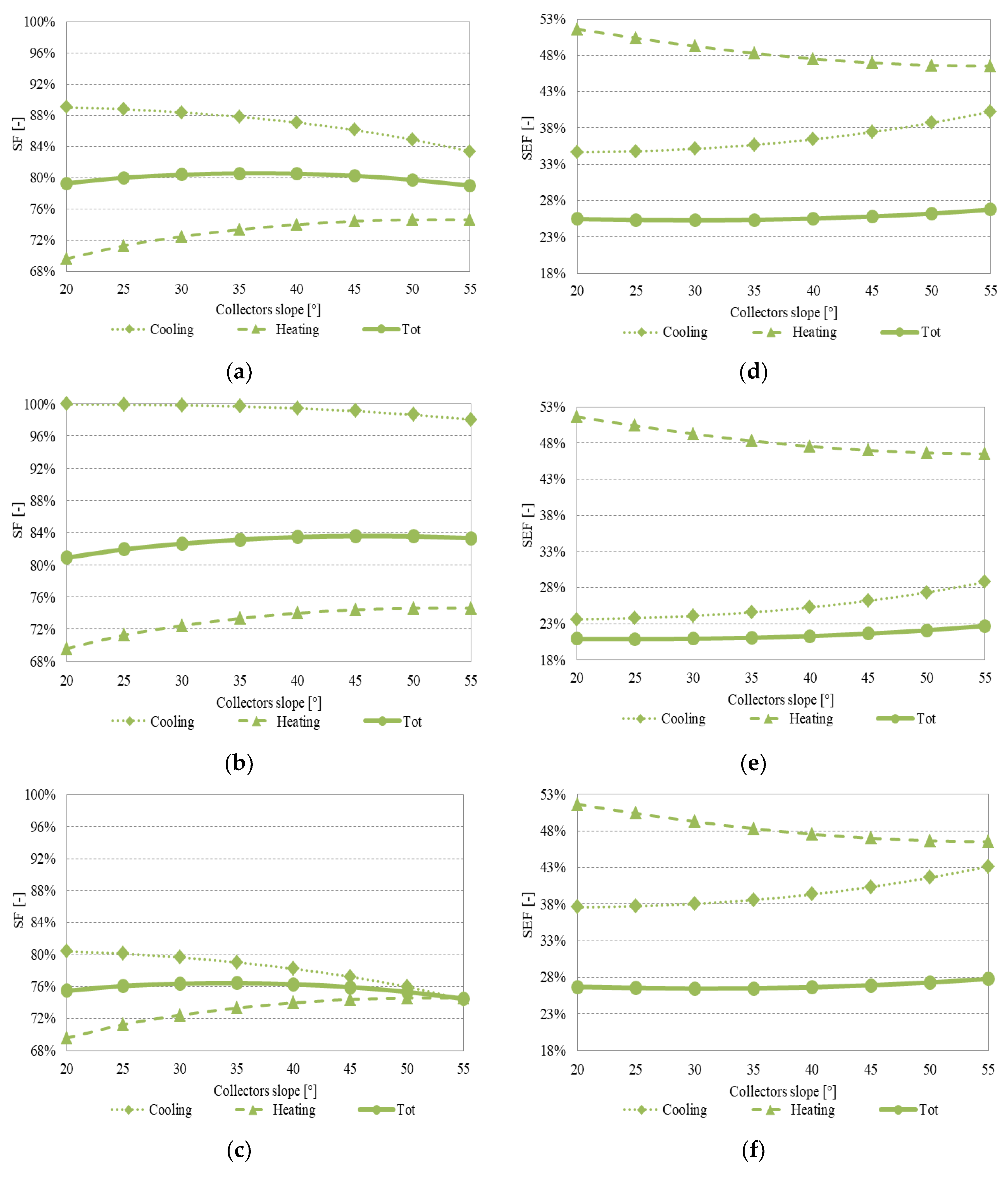
the solar fraction (SF), that is the share of thermal enegy from the solar subsystem on the total thermal energy required by the AHU in the IS;
-
the solar energy factor (SEF), that represents the ratio between the solar energy used in the AHU and that totally available.
The values of SF and SEF have been calculated on an annual and seasonal base. Concerning the solar fraction and the solar energy factor in cooling mode, SF and SEF are:
-
the ratio between the solar energy used to regenerate the desiccnt wheel ( E t h T S D W r e g ) and the total regeneration energy ( E t h D W r e g ):
S F C o o l i n g = E t h T S D W r e g E t h D W r e g
-
the ratio between the solar energy used to regenerate the desiccant rotor and the total termal energy available from SC in summer ( E t h ,   C o o l i n g S C ),
S E F C o o l i n g = E t h T S D W r e g E t h ,   C o o l i n g S C
In heating mode SF is the ratio between the solar thermal energy supplied for pre-heating ( E t h T S p r e h e a t ) and post-heating ( E t h T S p o s t h e a t ) and the total thermal energy for pre and post-heating ( E t h p r e h e a t + E t h p o s t h e a t ), whereas the solar energy factor in the denominator has the total thermal energy from SC in the winter period ( E t h , H e a t i n g S C ):
S F H e a t i n g = E t h T S p r e h e a t + E t h T S p o s t h e a t E t h p r e h e a t + E t h p o s t h e a t
S E F H e a t i n g = E t h T S p r e h e a t + E t h T S p o s t h e a t E t h , H e a t i n g S C
The total solar fraction and energy factor are, instead, evaluated as:
S F T o t a l = E t h T S D W r e g + E t h T S p r e h e a t + E t h T S p o s t h e a t E t h D W r e g + E t h p r e h e a t + E t h p o s t h e a t
S E F T o t a l = E t h T S D W r e g + E t h T S p r e h e a t + E t h T S p o s t h e a t E t h , T o t a l S C
The following further two indexes provide a comparison between the IS and CS (Figure 2). They evalute respectively:
-
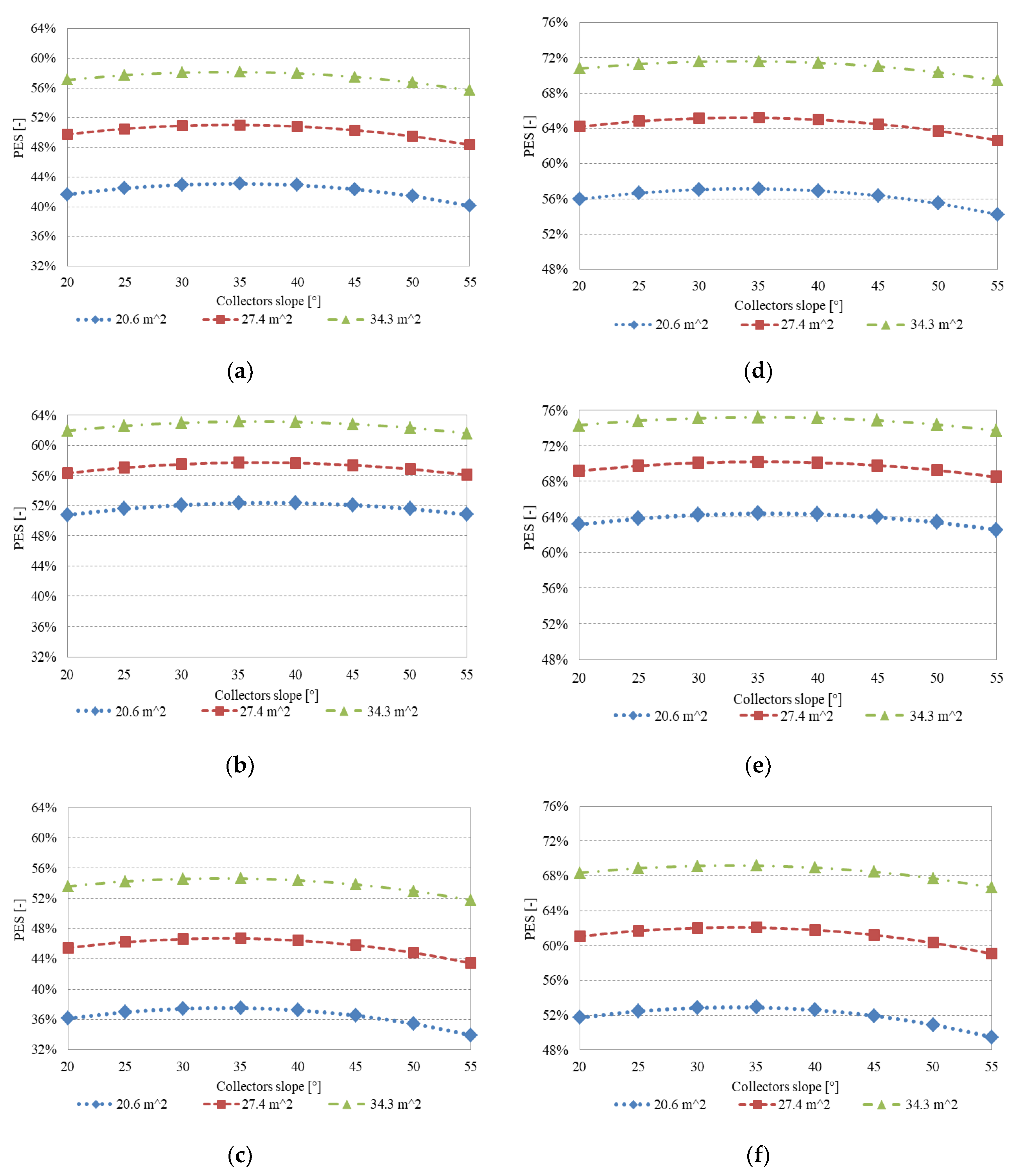
the primary energy saving (PES) achieved by IS with respect to CS;
-
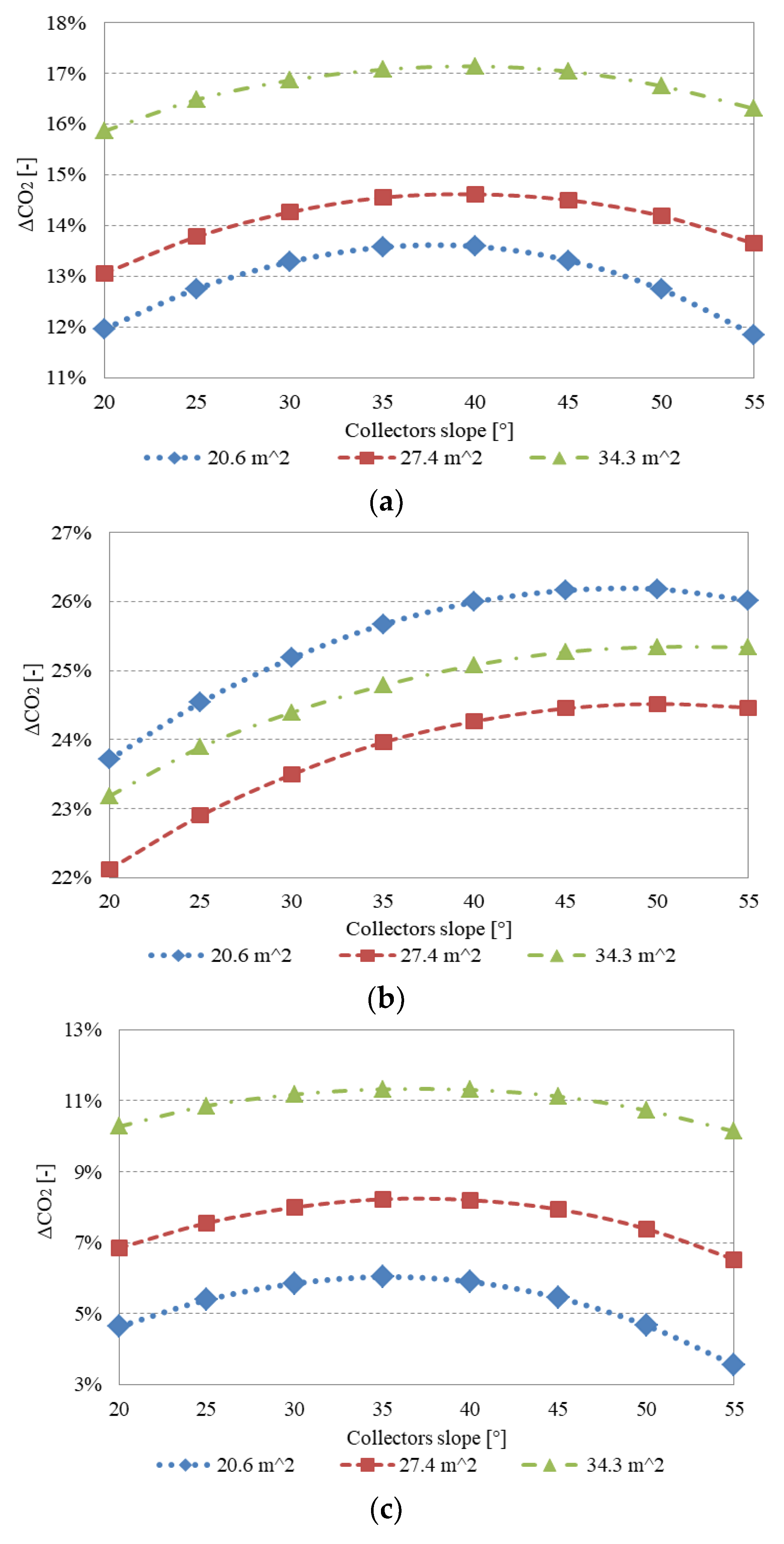
the equivalent CO2 emissions avoided by IS with respect to CS.
Concerning energy analysis, the comparison of IS and CS is performed considering only the primary energy demands related to fossil fuels, in fact the PES of non-renewable energy sources is:
P E S = ( 1 E p I S / E p C S ) × 100
where:
E p A S / C S = ( E e l , C H I S / C S + E e l , a u x I S / C S + E e l , n o n H V A C U S ) / η E G + E t h , B I S / C S / η B
and:
E e l , a u x I S = E e l D C + E e l , p u m p s I S + E e l , A H U I S ,
E e l , a u x C S = E e l , p u m p s C S + E e l , A H U C S
The primary energy of the innovative and conventional system ( E p I S / C S ) is assessed taking into account that the Italian national electric system energy efficiency (ηEG), including transmission and distribution losses, is 42% [30], and using the boiler efficiency reported before (namely 90.2%). Furthermore, it is considered that solar energy does not determine a primary energy as it is a renewable energy source.
To assess the positive effects on the environment of the IS installation, equivalent CO2 emissions of the two systems have been calculated and the equivalent avoided CO2 emissions have been derived:
C O 2 = ( 1 C O 2 I S / C O 2 C S ) × 100
where:
C O 2 I S / C S = ( E e l , C H I S / C S + E e l , a u x I S / C S + E e l , n o n H V A C U S ) · α + E t h , B I S / C S · β / η B
The specific emission factor of primary energy related to natural gas combustion, β, is equal to 0.207 kg CO2/kW hp, [30] while α, the specific emission factor of electricity drawn from the Italian grid, is equal to 0.573 kg CO2/kW hel [30].
In addition to the results, already reported in [30] for the silica-gel DW, in this work the energy and environmental indexes are extended to the innovative plants with MILGO and zeolite-rich tuff DWs.

4. Results

In the following subsections the results of the energy and environmental analyses will be shown grouping figures related to the same index, one subfigure for each hygroscopic material considered. The label “a” will refer to silica-gel, “b” to MILGO and “c” to zeolite-rich tuff. Each subfigure will contain data for different tilt angles (the analyses have been carried out considering tilt angles ranging from 20° to 55°), solar field collecting surfaces (three areas have been evaluated for the solar collectors field, namely 20, 27 and 34 m2) or seasonal information (operation in cooling and heating mode).

4.1. Energy Analysis

On an annual basis the comparison of the proposed innovative system and the conventional one determines the results, in terms of PES, reported in Figure 3. The best performance was reached by the MILGO DW, for which PES was close to 29%, while in the case of silica-gel the maximum PES was slightly over 20%, and with the zeolite tuff DW it was about 14% in the best layout. For all three hygroscopic materials the widest collecting surface (about 34 m2) determines the best energy results, but while with silica-gel and zeolite-rich tuff DW PES decreases when collector surface becomes smaller (Figure 3a,c), this does not happen with MILGO. The anomalous trends of Figure 3b are explained by the reduced amount of thermal energy needed to regenerate MILGO; the benefits in regeneration obtained with 27 m2 of solar collectors, instead of 20 m2, do not compensate the energy costs for dissipation; the situation changes at 34 m2. The low regeneration energy of MILGO is further proven by the optimum tilt angle, which is about 50°, because the plant energy behavior is mainly influenced by the winter energy demand, in this situation solar energy is better exploited with a high tilt angle.
In order to assess the share of thermal energy supplied to the innovative AHU by the solar subsystem with respect to the total thermal energy demand, the SF has been evaluated in all the plant configurations and considering the operation in cooling mode (dotted line), heating mode (dashed line) and total (continuous line). Figure 4 shows the results for 20 m2 of evacuated tube solar collectors and Figure 5 and Figure 6 show the results for 27 and 34 m2, respectively.
The SF during the cooling period shows a decreasing trend with the tilt angle in all the simulated cases and it is often higher than SFHeating, that, instead has an opposite behavior. The total SF that takes into account both trends highlighted a maximum that is shifted more to the left or more to the right depending on the desiccant material considered. MILGO DW regeneration required low thermal energy, so the SFCooling is higher than in the plants with silica-gel and zeolite-rich tuff DWs; it is equal to 100% with 34 m2 of solar collectors. In this case, the corresponding SFTotal shows a maximum for high value of the tilt angle because it is affected mainly by winter operation. On the contrary, the zeolite-rich tuff DW-based plants needed more regeneration energy, therefore, SFCooling is lower than for the AHU with silica-gel and MILGO DWs while the SFTotal shows a maximum at about 35°. The winter SF did not depend on the hygroscopic material considered and changed only with tilt angle and collecting surface.
In order to have an idea of the amount of solar thermal energy exploited and of that dissipated, SEF is introduced. As for SF the SEFHeating index is independent from the DW material, it decreases with tilt angle and is lower when the collecting surface increases, because the dissipated solar thermal energy decreases. The solar thermal energy is used for a percentage in the range of 57–60% when 20 m2 of evacuated tube solar collectors are considered, these percentages decrease to 52–56% and to 46–52% with the wider solar fields.
The solar energy factor for the summer period assumes lower values with respect to SEFHeating especially with MILGO DWs; in the worst case (34 m2 solar collector and 20° tilt angle) it is equal to just over 23%, demonstrating a large amount of solar energy dissipated. This consideration is, in general, always true, SEFCooling is lower than SEFHeating, by about 50% in the best case. Unfortunately, the low seasonal SEF derived from the weekend days when the air-conditioning system is not working. All year round the solar energy factor is further reduced due to the long period in the intermediate season in which the HVAC system is switched off. In addition it can be noted that SFTotal trend is quite flat and it is not affected by the tilt angle.

4.2. Environmental Analysis

In terms of avoided equivalent CO2 emissions, the air-conditioning plants with silica-gel DW and those with zeolite-rich tuff DW have similar behaviors but the environmental performances with the conventional material are better than with tuff (Figure 7a,c). The parameter ΔCO2 increases with the solar field aperture area and in the best case is about 17% and 11% with silica-gel and zeolite-rich tuff, respectively. The optimal tilt angle is close to 40° with the standard material while it moves towards 35° with tuff. MILGO DW-based plants use large amount of solar thermal energy and are responsible for low emissions, in fact, also in worst case higher ΔCO2 are reached. As for PES, the largest solar collecting surface does not correspond with the best ΔCO2 (Figure 7b). On the contrary, the lowest emissions take place with the 20 m2 solar field because there is the minimum demand of electricity for dissipation ( E e l D C ).

5. Discussion

The indexes SFs and SEFs showed that the solar heating and cooling proposed plant is not well coupled with the user considered. A large share of solar thermal energy remains unused and needs to be dissipated, increasing the electricity demand. Consequently, if half this solar thermal energy in excess is exploited for other low temperature energy use, PES and ΔCO2 increase significantly, approaching 63% and 60%, respectively.
The best results pertain to the configuration with MILGO DW, 34 m2 of solar collectors, and a tilt angle of 35° (see Figure 8b and Figure 9b). If the thermal energy surplus is completely considered for other applications in nearby users, the primary energy saving and the equivalent CO2 emissions reach values over 65% under all the considered cases with a solar field of 34 m2. Even when the smallest collecting surface (20 m2) is considered, the energy and environmental indexes reach and exceed 50% (see Figure 8 (right side), and Figure 9 (right side)).
The worst performances are observed using the tuff-based DW configuration, as a consequence of the climatic conditions chosen for carrying out this analysis. Campanian Ignimbrite-based DW, despite using a very cheap material largely available in the surroundings of Benevento, has interesting performances when compared to other hygroscopic materials only when relative humidity is low and the regeneration air temperature is very high, as reported by [19].
A further analysis based on economic considerations may be carried out in the future when there will be a clearer idea of the production costs of a DW based on tuff. It is considered likely that the initial cost of an AHU with a tuff desiccant wheel will be significantly lower with respect to the other two materials, therefore it will be necessary to see if the higher operating costs due to poorer performance will justify the adoption of this natural material.

6. Conclusions

In this paper three DWs made of silica-gel, MILGO and zeolite-rich tuff have been considered in a desiccant based solar-driven air handling unit that operates for the air-conditioning of a university classroom located in Benevento. First of all, the performance of these innovative plants are compared with that of a conventional system; positive results are achieved under all the configurations considered, as demonstrated by the parametric study performed considering different evacuated tube solar collectors surfaces (about 20, 27 and 34 m2) and tilt angle (20–55°). A comparison of the three innovative AHUs highlights that the best performances are demonstrated by the MILGO wheel system, while the poorest performances are those obtained by the tuff-based system. In the best case (MILGO DW, with a solar field of 34 m2 and a tilt angle of about 50°) the primary energy saving approaches 29%. With respect to the equivalent CO2 emissions, the optimal configuration does not overlap with the one characterized by the widest solar collector aperture area but, on the contrary, the best solution is the one with the smallest solar field. As demonstrated by the solar fraction and solar energy factor parameters, there is a large share of solar thermal energy surplus that needs to be dissipated, and this increases the electricity demand. Silica-gel DW-based plants show to be a more balanced solution for the solar thermal energy available in the studied location, while the tuff rotor operating far from its best operating conditions does not offer optimal performances.
When one takes in to account the possibility to further and totally use the solar energy in excess for other low temperature applications, for example in nearby users, the primary energy saving and the equivalent CO2 emissions avoided boost up to 75% and 73%, respectively.

Author Contributions

The Authors have complementary expertise on the main topics of this paper and they jointly shared the structure and aims of the manuscript. More specifically, C.R. and F.T. dealt more with the air-conditioning plant modeling and simulation, P.B. and F.P. dealt more with the desiccant wheel materials, M.S. contributed more to the energy and environmental analysis. Finally, all the Authors equally contributed during the writing of the paper.

Funding

This research received no external funding.

Conflicts of Interest

The authors declare no conflict of interest.

Nomenclature

CO2Equivalent CO2 emission (kg/year)
cpSpecific heat (J/kgK)
DsSurface diffusion coefficient (m2/s)
EEnergy (MWh/y)
F1, F2Isopotential lines
KEffective mass transfer coefficient (1/s)
kThermal conductivity (W/mK)
MMoisture content of adsorbent material (kgwater/kgadsorbent)
MwMolecular weight of water (kg/mol)
PESPrimary Energy Saving (%)
qsisosteric heat of adsorption (J/mol)
SEFSolar Energy Factor (-)
SFSolar Fraction (-)
T, tTemperature (K), (°C)
Vair superficial velocity (m/s)
zAxial coordinate (m)
Greek symbols
αSpecific emission factor of electricity drawn from the grid (kg CO2/kW hel)
βSpecific emission factor of primary energy related to natural gas combustion (kg CO2/kW hEp)
ΔCO2Equivalent CO2 avoided emission (%)
εVoid fraction (-)
ηEfficiency (-)
θTime (s)
ρDensity (kg/m3)
ωAir absolute humidity (kgwater/kgdry air) or (gwater/kgdry air)
Superscripts
CSConventional System
DCDry cooler
DWregDesiccant Wheel regeneration
ISInnovative System
postheatPost-heating phase
preheatPre-heating phase
TSThermal Storage
USUser
Subscripts
ambAmbient
auxAuxiliaries
BBoiler
CHChiller
CoCooling
CoolingCooling mode
dAdsorbent materia
eAt equilibrium condition
EGElectric Grid
elElectric
F1, F2Isopotential lines
HeatingHeating mode
inInitial
mmoist air
non-HVACnot related to HVAC
pPrimary
PPPower Plant
procProcess
regRegeneration
SCSolar thermal Collector
thThermal
tot, TotalTotal
Acronyms
AHUAir Handling Unit
BBoiler
CCCooling Coil
CFCross-Flow heat exchanger
CHChiller
COPCoefficient Of Performance
CSConventional System
DWDesiccant Wheel
ECEvaporative Cooler
HC, HC2Heating Coils
HVACHeating, Ventilation and Air-Conditioning
HW-HXHot Water Heat exchanger
ISInnovative System
MILGO Hygroscopic material, consisting graphite oxide dispersed in the MIL101 metal organic framework network structure
SCSolar thermal Collector
SEFSolar Energy Factor
SFSolar Fraction
TSThermal Storage

References

  1. Zheng, X.; Ge, T.S.; Wang, R.Z. Recent progress on desiccant materials for solid desiccant cooling systems. Energy 2014, 74, 280–294. [Google Scholar] [CrossRef]
  2. Asim, N.; Emdadi, Z.; Mohammad, M.; Yarmo, M.A.; Sopian, K. Agricultural solid wastes for green desiccant applications: An overview of research achievements, opportunities and perspectives. J. Clean. Prod. 2015, 91, 26–35. [Google Scholar] [CrossRef]
  3. Jani, D.B.; Mishra, M.; Sahoo, P.K. Performance analysis of a solid desiccant assisted hybrid space cooling system using TRNSYS. J. Build. Eng. 2018, 19, 26–35. [Google Scholar] [CrossRef]
  4. Al-Alili, A.; Hwang, Y.; Radermacher, R. Performance of a desiccant wheel cycle utilizing new zeolite material: Experimental investigation. Energy 2015, 81, 137–145. [Google Scholar] [CrossRef]
  5. Kanoğlu, M.; Çarpınlıoğlu, M.Ö.; Yıldırım, M. Energy and exergy analyses of an experimental open-cycle desiccant cooling system. Appl. Therm. Eng. 2004, 24, 919–932. [Google Scholar] [CrossRef]
  6. Subramanyam, N.; Maiya, M.P.; Srinivasa Murthy, S. Application of desiccant wheel to control humidity in air-conditioning systems. Appl. Therm. Eng. 2004, 24, 2777–2788. [Google Scholar] [CrossRef]
  7. Jia, C.X.; Dai, Y.J.; Wu, J.Y.; Wang, R.Z. Experimental comparison of two honeycombed desiccant wheels fabricated with silica gel and composite desiccant material. Energy Convers. Manag. 2006, 47, 2523–2534. [Google Scholar] [CrossRef]
  8. White, S.D.; Goldsworthy, M.; Reece, R.; Spillmann, T.; Gorur, A.; Lee, D.Y. Characterization of desiccant wheels with alternative materials at low regeneration temperatures. Int. J. Refrig. 2011, 34, 1786–1791. [Google Scholar] [CrossRef]
  9. Eicker, U.; Schürger, U.; Köhler, M.; Ge, T.; Dai, Y.; Li, H.; Wang, R. Experimental investigations on desiccant wheels. Appl. Therm. Eng. 2012, 42, 71–80. [Google Scholar] [CrossRef]
  10. Jia, C.X.; Dai, Y.J.; Wu, J.Y.; Wang, R.Z. Analysis on a hybrid desiccant air-conditioning system. Appl. Therm. Eng. 2006, 26, 2393–2400. [Google Scholar] [CrossRef]
  11. Fong, K.F.; Lee, C.K. Impact of adsorbent characteristics on performance of solid desiccant wheel. Energy 2018, 144, 1003–1012. [Google Scholar] [CrossRef]
  12. Intini, M.; Goldsworthy, M.; White, S.; Joppolo, C.M. Experimental analysis and numerical modelling of an AQSOA zeolite desiccant wheel. Appl. Therm. Eng. 2015, 80, 20–30. [Google Scholar] [CrossRef]
  13. Goldsworthy, M.J. Measurements of water vapour sorption isotherms for RD silica gel, AQSOA-Z01, AQSOA-Z02, AQSOA-Z05 and CECA zeolite 3A. Microporous Mesoporous Mater. 2014, 196, 59–67. [Google Scholar] [CrossRef]
  14. Enteria, N.; Yoshino, H.; Mochida, A.; Satake, A.; Yoshie, R.; Takaki, R.; Yonekura, H.; Mitamura, T.; Tanaka, Y. Performance of solar-desiccant cooling system with silica–gel (SiO2) and titanium dioxide (TiO2) desiccant wheel applied in East Asian climates. Sol. Energy 2012, 86, 1261–1279. [Google Scholar] [CrossRef]
  15. Rajamani, M.; Maliyekkal, S.M. Chitosan reinforced boehmite nanocomposite desiccant: A promising alternative to silica gel. Carbohydr. Polym. 2018, 194, 245–251. [Google Scholar] [CrossRef] [PubMed]
  16. Yan, J.; Yu, Y.; Ma, C.; Xiao, J.; Xia, Q.; Li, Y. Adsorption isotherms and kinetics of water vapor on novel adsorbents MIL-101(Cr)@GO with super-high capacity. Appl. Therm. Eng. 2015, 84, 118–125. [Google Scholar] [CrossRef]
  17. Caputo, D.; Iucolano, F.; Pepe, F.; Colella, C. Modeling of water and ethanol adsorption data on a commercial zeolite-rich tuff and prediction of the relevant binary isotherms. Microporous Mesoporous Mater. 2007, 105, 260–267. [Google Scholar] [CrossRef]
  18. Bareschino, P.; Diglio, G.; Pepe, F.; Angrisani, G.; Roselli, C.; Sasso, M. Numerical study of a MIL101 metal organic framework based desiccant cooling system for air conditioning application. Appl. Therm. Eng. 2017, 124, 641–651. [Google Scholar] [CrossRef]
  19. Bareschino, P.; Diglio, G.; Pepe, F. Modelling of a Zeolite-Rich Tuff Desiccant Wheel. Adv. Sci. Lett. 2017, 23, 6002–6006. [Google Scholar] [CrossRef]
  20. Maclaine-Cross, I.L.; Banks, P.J. Coupled heat and mass transfer in regenerators– predictions using an analogy with heat transfer. Int. J. Heat Mass Transf. 1972, 15, 1225–1242. [Google Scholar] [CrossRef]
  21. Howe, R.R. Model and Performance Characteristics of a Conditioning System Which Utilizes a Rotary Desiccant Dehumidifier. Master’s Thesis, University of Wisconsin, Madison, WI, USA, 1983. [Google Scholar]
  22. Jurinak, J.J. Open Cycle Solid Desiccant Cooling: Component Models and System Simulations. Ph.D. Thesis, University of Wisconsin, Madison, WI, USA, 1982. [Google Scholar]
  23. Banks, P.J. Prediction of Heat and Mass Regenerator performance using nonlinear analogy method: Part 1—basis. ASME J. Heat Transf. 1985, 107, 222–229. [Google Scholar] [CrossRef]
  24. Angrisani, G.; Roselli, C.; Sasso, M. Experimental validation of constant efficiency models for the subsystems of an unconventional desiccant-based Air Handling Unit and investigation of its performance. Appl. Therm. Energy 2012, 33–34, 100–108. [Google Scholar] [CrossRef]
  25. Solar Energy Laboratory. TRNSYS 17, a TRaNsient System Simulation Program; University of Wisconsin: Madison, WI, USA, 2010. [Google Scholar]
  26. Thermal Energy System Specialists Components Library v. 17.01; Thermal Energy System Specialists: Madison, WI, USA, 2004.
  27. Angrisani, G.; Roselli, C.; Sasso, M.; Tariello, F.; Vanoli, G.P. Performance Assessment of a Solar-Assisted Desiccant-Based Air Handling Unit Considering Different Scenarios. Energies 2016, 9, 724. [Google Scholar] [CrossRef]
  28. Angrisani, G.; Roselli, C.; Sasso, M.; Tariello, F. Dynamic performance assessment of a micro-trigeneration system with a desiccant-based air handling unit in Southern Italy climatic conditions. Energy Convers. Manag. 2014, 80, 188–201. [Google Scholar] [CrossRef]
  29. Angrisani, G.; Canelli, M.; Roselli, C.; Sasso, M. Calibration and validation of a thermal energy storage model: Influence on simulation results. Appl. Therm. Eng. 2014, 67, 190–200. [Google Scholar] [CrossRef]
  30. Angrisani, G.; Roselli, C.; Sasso, M.; Tariello, F. Dynamic performance assessment of a solar-assisted desiccant-based air handling unit in two Italian cities. Energy Convers. Manag. 2016, 113, 331–345. [Google Scholar] [CrossRef]
Figure 1. Alternative system layout in cooling mode (a) and heating mode (b).
Energies 12 01543 g001
Figure 2. Scheme of the innovative and conventional systems.
Energies 12 01543 g002
Figure 3. Primary energy savings as a function of the tilt angle and the solar field aperture area for: (a) silica-gel DW, (b) MILGO DW and (c) zeolite-rich tuff DW.
Energies 12 01543 g003
Figure 4. Solar fraction (left side) and solar energy factor (right side) as a function of the tilt angle in cooling operation, heating operation and total, for the plant with 20 m2 of solar collectors and the innovative AHU equipped with: (a,d) silica-gel DW, (b,e) MILGO DW and (c,f) zeolite-rich tuff DW.
Energies 12 01543 g004
Figure 5. Solar fraction (left side) and solar energy factor (right side) as a function of the tilt angle in cooling operation, heating operation and total, for the plant with 27 m2 of solar collectors and the innovative AHU equipped with: (a,d) silica-gel DW, (b,e) MILGO DW and (c,f) zeolite-rich tuff DW.
Energies 12 01543 g005
Figure 6. Solar fraction (left side) and solar energy factor (right side) as a function of the tilt angle in cooling operation, heating operation and total, for the plant with 34 m2 of solar collectors and the innovative AHU equipped with: (a,d) silica-gel DW, (b,e) MILGO DW and (c,f) zeolite-rich tuff DW.
Energies 12 01543 g006
Figure 7. Equivalent CO2 emissions avoided as a function of the tilt angle and the solar field aperture area for: (a) silica-gel DW, (b) MILGO DW and (c) zeolite-rich tuff DW.
Energies 12 01543 g007
Figure 8. Primary energy savings as a function of the tilt angle and the solar field aperture area when half of the solar thermal energy surplus is used (left side) and when it is totally used (right side) for: (a,d) silica-gel DW, (b,e) MILGO DW and (c,f) zeolite-rich tuff DW.
Energies 12 01543 g008
Figure 9. Equivalent avoided CO2 emissions as a function of the tilt angle and the solar field aperture area when half of the solar thermal energy surplus is used (left side) and when it is totally used (right side) for: (a,d) silica-gel DW, (b,e) MILGO DW and (c,f) zeolite-rich tuff DW.
Energies 12 01543 g009
Table 1. Classroom envelope characteristics [27].
ParameterOpaque ComponentsTransparent Components
RoofExternal Walls (N/S)External Walls (E/W)On the Ground FloorNorthSouthEast/West
U (W/m2 K)2.301.111.110.2972.832.832.83
Area (m2)63.53615.8763.58.539.400.976
g (-)----0.7550.7550.755
Table 2. Main TRNSYS submodels considered for the simulation and their main parameters.
Component (Reference)TypeLibraryMain ParametersValueUnits
Cross flow heat exchanger [24]91StandardEffectiveness0.446-
Humidifier [24]506 cTESSSaturation efficiency0.551-
Natural gas boiler [24]6StandardNominal thermal power24.1kW
Efficiency0.902-
Air-cooled chiller [24]655TESSRated capacity8.50kW
Rated COP2.98-
Heating coil [24]670TESSLiquid specific heat4.190kJ/(kg·K)
Effectiveness0.864-
Cooling coil [24]508TESSLiquid specific heat4.190kJ/(kg·K)
Bypass fraction0.177-
Storage tank [29]60 fStandardVolume971L
Height2.04m
Tank loss coefficient1.37W/(m2·K)
Liquid specific heat4.190kJ/(kg·K)
Evacuated solar collectors71StandardTested flow rate8.43 × 10−3kg/(s·m2)
Intercept efficiency 0.676-
Efficiency slope 1.15W/(m2·K)
Efficiency curvature 0.004W/(m2·K2)
Fluid specific heat3.85kJ/(kg·K)

