Simulation and Protection of Lightning Electromagnetic Pulse in Non-Metallic Nacelle of Wind Turbine

1
Shanghai Key Laboratory of Power Station Automation Technology, School of Mechatronics Engineering and Automation, Shanghai University, Shanghai 200444, China
2
Electric Power College, Shanghai University of Electric Power, Shanghai 200090, China
*
Authors to whom correspondence should be addressed.
Energies 2019, 12(9), 1745; https://doi.org/10.3390/en12091745
Submission received: 3 April 2019
/
Revised: 30 April 2019
/
Accepted: 3 May 2019
/
Published: 8 May 2019
(This article belongs to the Special Issue Modeling of Wind Turbines and Wind Farms)
Abstract
:When the nacelle of a wind turbine is struck by lightning, lightning electromagnetic pulse (LEMP) is generated inside the nacelle and consequently impacts inside electronic devices or even seriously destroys them. In order to study the LEMP inside the nacelle, this paper firstly built a full-scale model of a non-metallic nacelle. The lightning electromagnetic environment in the nacelle was simulated and analyzed by the transmission-line matrix method. Then the protective measures of applying metallic shielding mesh on the nacelle were studied, including the mesh size and material of the shielding mesh on the protective effect. The results show that LEMP in the nacelle can be effectively attenuated by metallic shielding meshes. The shielding effect is highly dependent on the conductivity of the shielding mesh material and the mesh size.
1. Introduction
Lightning is a large-scale discharge phenomenon between cloud and cloud or between cloud and ground, as a natural typical electromagnetic hazard source [1,2]. Especially when cloud-to-ground lightning happens, the lightning channel carries hundreds of thousand Ampere current and the rate of rise-time is tens of thousands A/μs. This generates a great thermal effect, dynamic effect and EM effect on sensitive electrical and electronic equipment [3,4].
Lightning strike is an important threat to the safe operation of wind turbine generators [5]. At present, the research on the mechanism of lightning damage to wind turbine mainly focuses on the damaging effect of direct lightning types. Based on the analysis of the development mechanism of “cloud-ground” linear lightning leader, the initial attachment area of the lightning strike was analyzed by the electrostatic field simulation method [6]. The influence of the number and size of blade terminals on the interception effect was analyzed. With the simplified model of the upstream leader development process of blades, a critical length criterion was proposed by using the finite element simulation software [7]. Cooray discussed the capability of some analytical equations, to estimate the lightning channel base current parameters through measured fields and draw a comparison among those analytical equations [8]. Nucci and Rachidi, who measured the lightning induced current of a shielded buried cable and the horizontal magnetic field, discussed the correlation between the horizontal magnetic field and lightning induced current [9]. Through the theory of attraction radius in the space method of lightning induction, the phenomenon of wind turbine shielding was analyzed [10], the maximum shielding failure probability and the probability of shielding failure were calculated, and the effect of adding special down-wire on lightning current discharge was discussed. A miniature model with 1:30 ratio of a typical 2 MW wind turbine generators was used [11], to simulate the tip linear velocity of the actual wind turbine generators, and the effect of blade rotation on clearance breakdown characteristics and lightning initiation ability was studied.
When the large lightning current is attached to the blade or nacelle of a wind turbine, the lightning current generates a strong lightning electromagnetic pulse (LEMP) around the wind turbine. Due to the electromagnetic coupling effect, surges are induced in the electronic equipment and cables in the nacelle, which leads to the malfunction or damage of the nacelle equipment, affecting the safe operation of wind turbines. With the development of “Intelligent Wind Turbine” more and more sensitive electronic devices, which are very vulnerable to LEMP, are used in wind turbine nacelle. In the past, the metallic enclosure of wind turbine nacelle had a good shielding effect on LEMP. However, in order to reduce the weight and cost of nacelles, composite non-metallic materials, such as GFRP (glass fiber reinforced plastics) are widely used as the enclosure of modern wind turbine nacelles. This makes LEMP more dangerous to the sensitive electronic equipment in the nacelle.
The lightning-induced surge in the cable is the main threat to damage electronic equipment. At present, the research on the coupling between the lightning electromagnetic field and cable mainly focuses on the long-distance coupling between overhead transmission line [12,13] and buried cable [14,15]. However, the research on the coupling effect between LEMP and cables in wind turbine nacelle has been little addressed. According to the lightning protection zones (LPZ) of wind turbines classified in IEC 61400-24 [16], the interior area of the wind turbine nacelle is LPZ1, but the electromagnetic field and surge levels in this area are not addressed.
This paper builds a three-dimensional model of the non-metallic wind turbine nacelle and studies the electromagnetic environment when the tail of the metallic nacelle is struck by lightning with the transmission line matrix method. The protective measures of applying metallic shielding mesh on the nacelle were studied, including the influence of the size and material of the shielding mesh on the shielding effect against LEMP.
2. Modeling Method
2.1. Principle of Transmission Line Modeling Method
The transmission-line matrix method (TLM) was first proposed by Johns and Beurle in 1971. Through continuous improvement and development, TLM algorithm has formed a complete time-domain electromagnetic radiation and scattering research method [17,18,19]. Its core idea is based on the similarity between electromagnetic wave transmission characteristics and voltage and current transmission characteristics in transmission lines. Now it has been extended to three-dimensional space problems.
When the TLM method is used to solve the distribution of electromagnetic field in medium, the medium characteristics are replaced by the TLM matrix, which is composed of intersections (nodes) of transmission lines after spatial discretization. The nodes represent the physical properties of different media, while the transmission lines only assume the distribution and storage of energy. By iterating the computational region from space and time, the distribution of magnetic field in the computational region with time and space can be obtained. The two-dimensional TLM method is composed of parallel transmission lines. The pulse source is incident from four branches to a node, and then scattered to the adjacent node. It can be expressed as:
where, S is the impulse scattering matrix of the nodes. C is the connection matrix describing the network topology. The subscripts k and k + 1 represent the scattering time interval. The following equation can be obtained as follows:
In the formula, k means scattering, i means incidence, m and n are port numbers.
In the three-dimensional electromagnetic field simulation, the symmetrical condensed node (SCN) algorithm is used to simulate the electromagnetic propagation in the space element [20]. A three-dimensional SCN node has six branches, each consisting of two transmission lines, which simulate the propagation of electric field and magnetic field, respectively. The cell size is often less than one-tenth of the corresponding wavelength of the highest simulation frequency [21].
In the narrow slot model, the field on the long side of the slot is separated by one-dimensional transmission line and symmetrical condensation node. The calculation formulas of capacitance CS and inductance LS per unit length of the slot in the element are as follows:
In the formula, ε is the relative dielectric constant in free space, μ is the relative permeability in free space, Δz is the distance of electromagnetic wave propagation in the time step Δt. w is the width of the gap and d is the depth of the gap.
The change of slot transmission line characteristic admittance YLINE and capacitive stump characteristic admittance YSTUB synchronizes the pulse of slot and stump with the time step of three-dimensional TLM unit, thus establishing the overall scattering model. The calculation formula is as follows:
where YLINE and YSTUB are transmission line characteristic admittance and capacitive stump characteristic admittance, respectively.
According to the above principle, the characteristics of LEMP in the nacelle wind turbine nacelle are studied by using a three-dimensional electromagnetic field simulation program.
2.2. Modeling of the Wind Turbine Nacelle
At present, the shell of most nacelles is made from GFRP (glass fiber reinforced plastics). Copper bars embedded inside the GFRP are used as the down-conductors. When lightning strikes at the tail of the nacelle, the lightning current will flow through the down-conductor copper bar into the MEB (main equipotential bar) located at the bottom of the nacelle and consequently flow into the ground through the tower. When large lightning current flows through the copper bar conductors, intense LEMP is generated inside nacelle, threatening the electric and electronic equipment. This paper built a 3D model of a non-metallic nacelle. In this paper, LEMP inside the nacelle was studied when the lightning current was injected into the lightning rod installed at the tail of the nacelle. The peak value and waveform of the lightning current is chosen as 200 kA and 10/350 μs according to the LPLI (lightning protection level) requirement in IEC 61400-24.
Figure 1 shows the model of real-scale wind turbine nacelle. The shell of the nacelle is made from glass fiber reinforced plastics (GFRP). The center of the nacelle bottom is set as the original point of the Cartesian coordinate system. Seven magnetic probes are placed at seven positions inside the nacelle, as follows, P1 (0, −300, 50), P2 (0, −200, 50), P3 (0, −100, 50), P4 (0, 0, 50), P5 (0, 100, 50), P6 (0, 200, 50), P7 (0, 300, 50).
Since there are different types of cables in the nacelle. Single-core cables without shielding layer and coaxial cables with shielding layer were selected as typical cables to represent them. One single-core cable and one RG58 coaxial cable of 6 m long were placed at 0.5 m height above the bottom of the nacelle. The induced voltage in the cables was evaluated. Then the inducing current could be easily evaluated along these cables once they were connected to different power sources and loads. In order to study the shielding effect after installing the shielding mesh over the nacelle shell, aluminum meshes with 50 mm, 20 mm and 10 mm size, respectively, were installed individually. In addition, the simulation frequency band was set at 0~30 MHz in the TLM method. The simulation step was 100 μs.
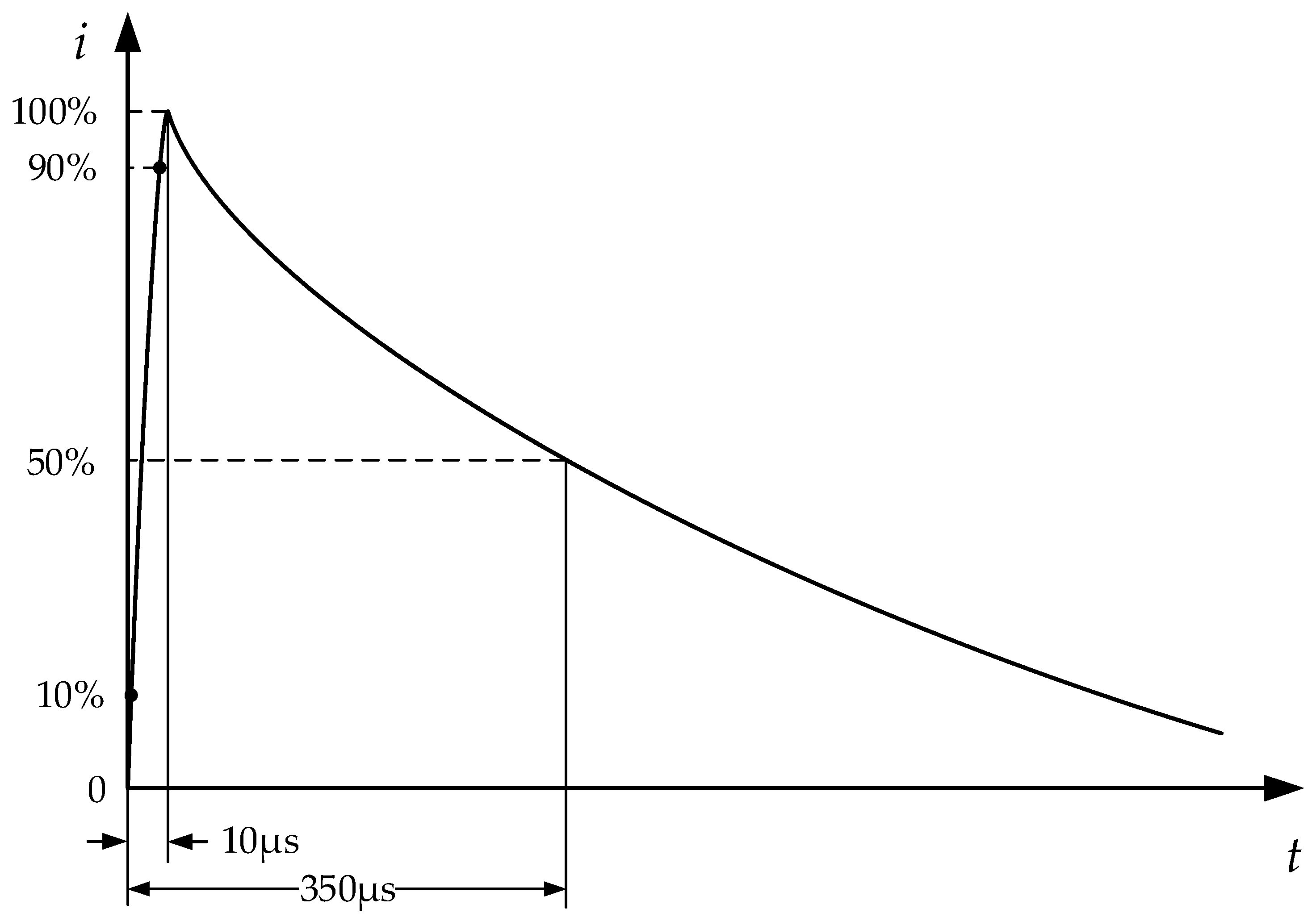
The Heidler model was used to simulate the natural lightning with 10/350 (μs) waveform, as follows [22],
where, Im is the peak value of lightning current (kA), k is the correction factor for the peak current, t is the time (μs), is the front time constant (μs) and is the tail time constant (μs). The lightning current is 200 kA, other corresponding parameters can be found in IEC 62305-1, Annex B.
k = 0.93,
3. Simulating Result and Analysis
3.1. Calculated LEMP inside Nacelle
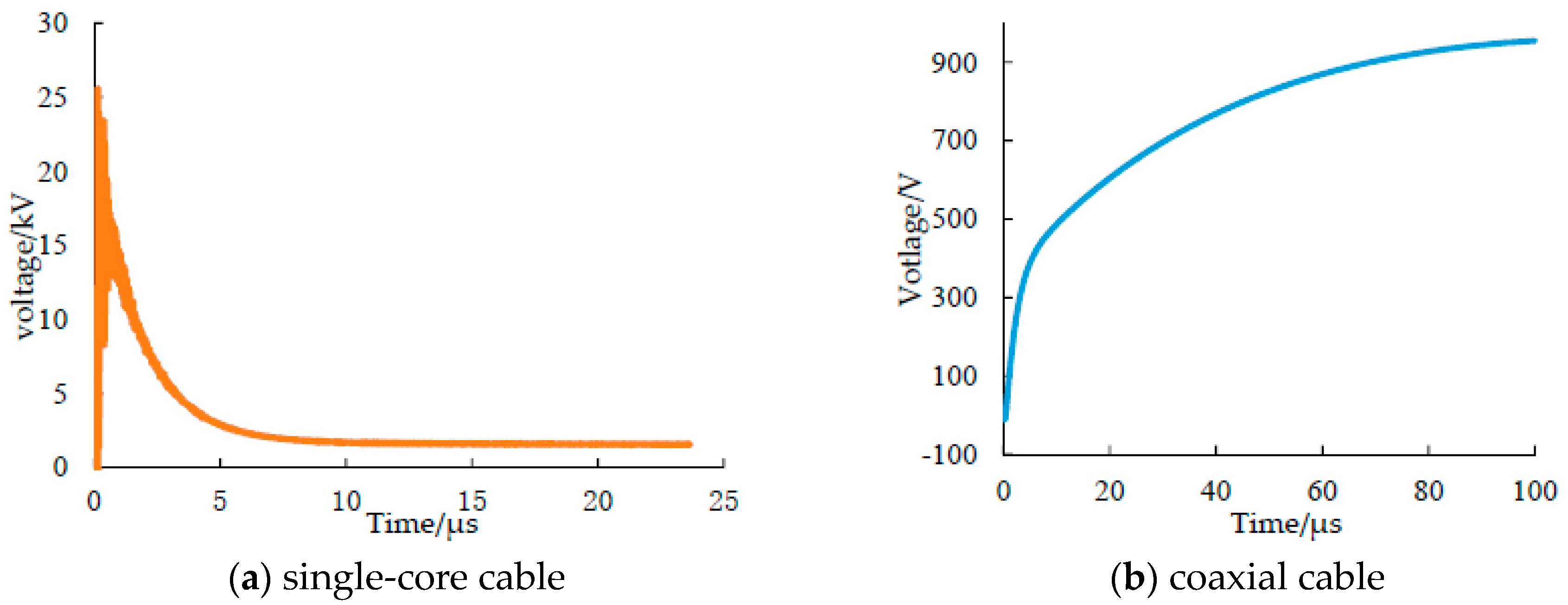
When lightning current flows through the copper bar embedded inside the shell of the nacelle, the induced voltage between the two terminals of the 6 m single-core cable and the coaxial cable is shown in Figure 3.
Figure 3 shows the variation of the induced voltage in different cables. From Figure 3, it is noted that the coupling characteristics of different cable structures have significant differences. Although the coaxial cable has a much better shielding effect than the single-core cable, the induced voltage at the coaxial cable can still reach over a thousand Volts. This is mainly due to the poor shielding ability of GFRP material on LEMP, resulting in the internal magnetic field strength of the nacelle not being well attenuated.
Figure 4 shows the time-domain variation of the magnetic field intensity at seven positions inside the GFRP nacelle. Although there are differences in the magnetic field intensity at different positions in the nacelle, the lightning magnetic field after 20 micros is almost all above 3 kA/m. Relevant studies show that when the magnetic field intensity reaches 190 A/m, some electronic components will be damaged [24,25]. Therefore, when the GFRP nacelle is directly exposed to LEMP, the electronic equipment will be threatened significantly.
3.2. Influence of the Mesh Size on the Shielding Effect
IEC61400-24 points out that a metallic mesh can be used in the nacelle with a GFRP cover to shield the external electric field and magnetic field, as well as the magnetic field generated by the current in the metallic mesh. For the nacelle shell made from GFRP, aluminum meshes with small mesh size will protect the nacelle from a direct lightning strike or the leader current. The magnetic field and electric field will be attenuated according to the mesh size and the thickness of the metallic material. In order to analyze the influence of mesh size on the attenuation, diamond aluminum meshes with the side lengths of l = 2 cm, 5 cm and 10 cm, respectively, were added to the nacelle shell to calculate the variation of the induced voltage in the cables and magnetic field in the nacelle. Figure 5 shows the time-domain variation of the induced voltage of the coaxial cable for different sizes of meshes. The result shows that adding metallic mesh can greatly reduce the induced voltage in the coaxial cable. After 100 micros, when the aluminum meshes with the side lengths is 2 cm, 5 cm and 10 cm, the induced voltage of coaxial cable is 80 V, 40 V and 16 V. At the same time, the smaller is the mesh size, the more obvious is the attenuation effect on the induced voltage in the cable, the smallest mesh has almost five times the shielding effect of the biggest mesh size. It is proportional to the mesh side length.
In order to investigate the distribution of the magnetic field in the nacelle with different mesh sizes, seven probes were located inside the nacelle as sampling points. The distance of each sampling point was 1 m. Figure 6 shows the magnetic field intensity at different points in the nacelle when the lightning current reached its peak value (t = 10 μs). It can be seen from Figure 6 that the magnetic field intensity increased gradually when the sampling points approached the lightning current outgo point. Comparing different mesh sizes, it is noted that when the mesh size is reduced from 10 cm to 2 cm, the magnetic field inside the nacelle is reduced by 90%, mostly.
3.3. Influence of the Mesh Material on the Shielding Effect
In order to study the influence of mesh material on the electromagnetic effect in the nacelle, the simulation with aluminum and steel was carried out and the simulation results were briefly analyzed. The conductivity of aluminum is 3.56 × 10⁷ S/m. The conductivity of steel is 7.69 × 10⁶ S/m. Figure 7 shows the current distribution on the nacelle surface with two mesh materials when the lightning current reached its peak value (t = 10 μs).
Figure 7 shows that when the material of shielding mesh is aluminum, the lightning current density can reach 260 kA/m at the lightning strike point and the edge of the nacelles. When the mesh material is steel, the lightning current density in the above area decreases to 225 kA/m. It can be concluded that the lightning current density on the nacelle’s surface decreases with the decrease of electrical conductivity, which is mainly due to the increase of Joule heat caused by the decrease of electrical conductivity, leading to a larger current attenuation, which shows that the lightning current intensity on the nacelles surface of the turbine is positively correlated with the electrical conductivity of the shell material.
The attenuation of magnetic field intensity was further studied with two mesh materials. Figure 8 shows the distribution of shield effect against the magnetic field at four sampling points (H1 (0, 0, 50), H2 (0, 0, 150), H3 (0, 0, 250), and H4 (0, 0, 350) with aluminum and steel materials. It is noted that the shielding ability of aluminum is much better than that of steel by nearly 30 dB.
By comparing the results in Figure 8, it shows that the shielding effect of the mesh on a nacelle against LEMP is reduced if the conductivity of the material is reduced. Especially, the wide application of composite materials in the wind turbine nacelle shell at present will inevitably bring serious risks to the internal electronic equipment. Therefore, in order to ensure the reliable and safe operation of the wind turbine, the metallic mesh is highly recommended to be installed over the composite shell to improve the anti-interference ability against LEMP.
4. Conclusions
A three-dimensional model of wind turbine nacelle with internal cables is established in this paper. The induced voltage in cables and the magnetic field distribution in the nacelle are studied by using the transmission line matrix method. The influence of shielding mesh size and material on the attenuation effect again magnetic field in the nacelle is also analyzed. Based on the above analysis, following conclusions are drawn:
- (1)
- When lightning strikes at the air terminal of the wind turbine nacelle, high transient voltage is induced in the cables inside the nacelle. Applying metallic mesh to the nacelle shell can effectively reduce the magnetic field inside the nacelle as well as the transient voltage in the cable.
- (2)
- The mesh material will obviously influence the shielding effect. The shielding effect of an aluminum mesh nacelle is nearly 30 dB higher than that of a steel mesh nacelle because of the higher conductivity of the aluminum mesh material.
- (3)
- The shielding effect is proportional to the mesh side length and the smaller mesh size has better shielding effect against the magnetic field and generates lower transient voltage in the cable. For example, the mesh with the side lengths is 2 cm has a five times shielding effect than the mesh with 5 cm side lengths.
With above study conclusion, it is suggested to apply metallic mesh with a higher conductive metallic material and smaller side length on the nacelle in order to attenuate LEMP inside the nacelle, e.g., aluminum mesh with 2 cm side length is preferred.
Author Contributions
All the authors contributed equally to this research work.
Funding
This work was financially supported by Shanghai Science and Technology Project under grant (16020501000).
Conflicts of Interest
The authors declare no conflict of interest. The funders had no role in the design of the study; in the collection, analyses, or interpretation of data; in the writing of the manuscript, or in the decision to publish the results.
References
- Zeng, R.; Zhuang, C.; Zhou, X.; Chen, S.; Wang, Z.; Yu, Z.; Jinliang, H. Survey of recent progress on lightning and lightning protection research. High Volt. 2016, 1, 2–10. [Google Scholar] [CrossRef]
- Wang, H.; Chen, Y.Z.; Wan, H.J.; Wang, X.J. Study on Coupling between Lightning Electromagnetic Field and Twisted Pair. J. Microw. 2014, 40, 1605–1613. [Google Scholar]
- Liu, S.H.; Liu, W.D. Progress of relevant research on electromagnetic compatibility and electromagnetic protection. High Volt. Eng. 2014, 40, 1605–1613. [Google Scholar]
- Zhou, Q.; Cheng, Y.; Bian, X.; Liu, F.; Zhao, Y. Analysis of Restrike Overvoltage of Circuit Breakers in Offshore Wind Farms. IEEE Trans. Appl. Supercond. 2016, 26, 1–5. [Google Scholar] [CrossRef]
- Yamamoto, K.; Noda, T.; Yokoyama, S.; Ametani, A. Experimental and analytical studies of lightning overvoltage in wind turbine generator systems. Electr. Power Syst. Res. 2009, 79, 436–442. [Google Scholar] [CrossRef]
- Zhou, Q.B.; Liu, C.X.; Bian, X.Y.; Lo, K.L.; Li, D.D. Numerical analysis of lightning attachment to wind trubine blade. Renew. Energy 2018, 116, 584–593. [Google Scholar] [CrossRef]
- Ma, Y.F.; Zhang, L.; Yan, J.Y.; Guo, Z.; Li, Q.; Fang, Z.; Siew, W.H. Inception mechanism of lightning upward leader from the wind turbine blade and a proposed critical length criterion. Proc. CSEE 2016, 36, 5975–5982. [Google Scholar]
- Gomes, C.; Cooray, V. On Theoretical Approaches to Estimate the Lightning Return Stroke Current Parameters. In Proceedings of the 11th International Symposium on High-Voltage Engineering (ISH 99), London, UK, 23–27 August 1999; p. v2-401. [Google Scholar]
- Petrache, E.; Paolone, M.; Rachidi, F.; Nucci, C.A.; Rakov, V.A.; Uman, M.; Jordan, D.; Rambo, K.; Schoene, J.; Cordier, A.; Verhaege, T. Measurement of Lightning-Induced Currents in an Experimental Coaxial Buried Cable. In Proceedings of the 2003 IEEE Power Engineering Society General Meeting, Toronto, ON, Canada, 13–17 July 2003. [Google Scholar]
- Zhou, C.Y. Analysis and protection of lightning shielding failure of wind turbine. Insul. Surge Arresters 2017, 1, 77–81. [Google Scholar]
- Wen, X.S.; Qu, L.; Wang, Y.; Si, T.; Xu, J.; Lan, L. Experimental study of the influence of the blade rotation on triggered lightning ability of wind turbine’s blades. Proc. CSEE 2017, 37, 2151–2158. [Google Scholar]
- Chen, W.J.; He, H.X.; He, J.J.; Zhao, X.; Yu, H.; Shi, W.; He, T. On the 3-dimentional leader progression model for the lightning shielding failure performance estimation of overhead transmission lines. Proc. CSEE 2014, 34, 6601–6612. [Google Scholar]
- Liu, G.; Xi, Y.; Tang, J.; Xi, Y.; Li, H.; Deng, L.; Xu, Z. Influence of triggered lightning of high voltage overhead transmission lines on 10 kV overhead distribution lines lightning trip characteristics. High Volt. Eng. 2014, 40, 690–697. [Google Scholar]
- Yu, H.; Dong, W.S.; Chen, S.D.; Wang, J.G.; Zhang, Y.J.; Zhang, Y.; Zhou, M.; Sun, Z.; Deqing, C.M. Observation and analysis of lightning induced overvoltage on buried cables. High Power Laser Part. Beams 2010, 22, 2373–2377. [Google Scholar] [CrossRef]
- Yang, B.; Zhou, B.H.; Chen, B.; Wang, J.B.; Meng, X. Numerical Study of Lightning-Induced Currents on Buried Cables and Shield Wire Protection Method. IEEE Trans. Electromagn. Compat. 2012, 54, 323–331. [Google Scholar] [CrossRef]
- Wind Turbines, Part 24 Lightning Protection: IEC 61400-24:2010; International Electrotechnical Commission: Geneva, Switzerland, 2010.
- Jojns, P.B.; Beurle, R.L. Numerical solution of 2-dimensional scattering problems using a transmission-line matrix. Proc. Inst. Electr. Eng. IET 1971, 118, 1203–1208. [Google Scholar]
- Hoefer, W.J.R. The Transmission-Line Matrix Method—Theory and Applications. IEEE Trans. Microw. Theory Tech. 1985, 33, 882–893. [Google Scholar] [CrossRef]
- Trenkic, V.; Christopoulos, C.; Benson, T.M. New symmetrical super-condensed node for the TLM method. Electr. Lett. 1994, 30, 329–330. [Google Scholar] [CrossRef]
- Johns, P.B. A Symmetrical Condensed Node for the TLM Method. IEEE Trans. Microw. Theory Tech. 1987, MTT-35, 370–377. [Google Scholar] [CrossRef]
- Johns, D.P.; Mallik, A.; Wlosarcyzk, A.J. TLM enhancements for EMC studies. In Proceedings of the 1992 Regional Symposium on Electromagnetic Compatibility, Tel-Aviv, Israel, 2–5 November 1992. [Google Scholar]
- Protection Against Lightning, Part 1 General Principles: IEC 62305-1:2010; International Electrotechnical Commission: Geneva, Switzerland, 2010.
- Zhang, X.Q. Lightning Protection and Ground Connection of Wind Turbines; China Electric Power Press: Beijing, China, 2009; pp. 20–22. [Google Scholar]
- Gong, X.H.; He, J.L.; Li, Y. Analysis on transient electromagnetic environment of substations. High Volt. Appar. 2009, 45, 39–43. [Google Scholar]
- Wang, X.H. Investigations on the Electromagnetic Effects in Wind Turbines Struck by Lightning; Jiao Tong University: Beijing, China, 2010. [Google Scholar]
Figure 1.
Model of wind turbine nacelle.

Figure 2.
10/350 lightning current waveform.

Figure 3.
Induced voltage in the cables in the nacelle.

Figure 4.
Magnetic field intensity time-domain variation diagrams of probes at different positions in the nacelle.
Figure 4.
Magnetic field intensity time-domain variation diagrams of probes at different positions in the nacelle.

Figure 5.
Induction voltage time domain variation diagrams of coaxial cables with different metal meshes.
Figure 5.
Induction voltage time domain variation diagrams of coaxial cables with different metal meshes.

Figure 6.
Magnetic field intensity values with different probes inside the nacelle.

Figure 7.
The distribution of surface current on the nacelle with two shielding materials during a lightning stroke.
Figure 7.
The distribution of surface current on the nacelle with two shielding materials during a lightning stroke.

Figure 8.
The attenuation value of the magnetic field on the probes.

© 2019 by the authors. Licensee MDPI, Basel, Switzerland. This article is an open access article distributed under the terms and conditions of the Creative Commons Attribution (CC BY) license (http://creativecommons.org/licenses/by/4.0/).
Share and Cite
MDPI and ACS Style
Zhou, Q.; Shi, Y.; Bian, X.; Zhou, B. Simulation and Protection of Lightning Electromagnetic Pulse in Non-Metallic Nacelle of Wind Turbine. Energies 2019, 12, 1745. https://doi.org/10.3390/en12091745
AMA Style
Zhou Q, Shi Y, Bian X, Zhou B. Simulation and Protection of Lightning Electromagnetic Pulse in Non-Metallic Nacelle of Wind Turbine. Energies. 2019; 12(9):1745. https://doi.org/10.3390/en12091745
Chicago/Turabian StyleZhou, Qibin, Yize Shi, Xiaoyan Bian, and Bo Zhou. 2019. "Simulation and Protection of Lightning Electromagnetic Pulse in Non-Metallic Nacelle of Wind Turbine" Energies 12, no. 9: 1745. https://doi.org/10.3390/en12091745
Note that from the first issue of 2016, this journal uses article numbers instead of page numbers. See further details here.