PMSG Control for a Stand-Alone Gas Engine Generator Using Active Rectifier and VSG-Controlled Inverter


1
Electrical, Electronics and Information Engineering Department, Osaka University, 2-1 Yamadaoka, Suita, Osaka 565-0871, Japan
2
Department of Electrical and Computer Engineering, Smart/Micro Grids Research Center, University of Kurdistan, Sanandaj 66177-14763, Iran
3
NARA-GAKUEN Incorporated Educational Institution, 3-12-1 Tatsunokita, Sangou-cho, Ikoma-gun, Nara 636-8503, Japan
*
Author to whom correspondence should be addressed.
Energies 2020, 13(1), 233; https://doi.org/10.3390/en13010233
Submission received: 30 November 2019
/
Revised: 21 December 2019
/
Accepted: 26 December 2019
/
Published: 2 January 2020
(This article belongs to the Section F: Electrical Engineering)
Abstract
:The engine generator system with a diode rectifier causes harmonic currents in the generator which can affect generator efficiency and may produce torque oscillations. Using an active rectifier instead of a diode rectifier helps us to improve the current waveforms. In this paper, an active rectifier is used for a stand-alone gas engine generation system with a permanent magnet synchronous generator (PMSG). The generator side converter and the load side converter can be controlled separately to achieve high performance and reliability of the system. In the proposed control framework, the generator side converter is controlled by means of a current vector control method in a cascade structure with the synchronous reference frame (dq- frame). In the proposed control scheme, the dc link voltage is controlled by the generator side converter. For load side converter control, the concept of virtual synchronous generator control method is adopted to support a smooth power transient during the load changes. To verify the usefulness of the proposed control structure, using PSCAD software (version 4.2.1), the system transient responses with both a diode rectifier and an active rectifier are investigated under loading and load removal cases. Moreover, for the system with an active rectifier, the transient response of the system with different vector control strategies of PMSG is also investigated.

1. Introduction
Gas engine generators are mobile electric power generation units that can operate in both stand-alone and grid-connected modes. Therefore, they are widely utilized in many commercial and industrial applications as well as in distributed generation systems [1,2,3,4,5,6]. In gas engine power generation systems, the generated electrical power is supplied to the load or to the grid by using a power electronic system which performs ac–dc–ac power conversion. In industry, two structures of power conversion can be used for the generator side converter. The first one is based on an uncontrolled diode rectifier which is simple and easy for the sake of implementation. The second one is the insulated gate bipolar transistors (IGBTs) based rectifier which can be controlled by the pulse width modulation (PWM) method. In both cases, the voltage source inverter is connected to the load or the power grid. The first technique causes high harmonic distortion in the generator currents. This leads to torque oscillations and overheating in the generator windings. Thus, the generator efficiency may be seriously affected. The harmonic distortions can be reduced by the second method. An application of the IGBT rectifier which is also known as an active rectifier can improve the current waveforms resulting in the increase of generator efficiency [7].
When the active rectifier is adopted in the gas engine generator system, the generator side converter and the load or grid side converter can be separately controlled to achieve a desirable performance and reliability of the system. The generator side converter control algorithm depends on the type of used generator in the system. The permanent magnet synchronous generator (PMSG) has been increasingly used in wind power systems owing to its higher efficiency, no excitation losses, less weight and smaller size in comparison of other types of generators [8,9]. The modelling and design of PMSG are analyzed in References [10,11,12]. The performance of PMSG in wind power systems is also investigated by applying various control approaches to the generator side converter [13,14,15,16,17,18,19,20]. A variable-speed PMSG system with a diode rectifier that is connected to a dc chopper is studied in References [13,14]. Despite a simple and low-cost solution, this system outputs high harmonic distortion current which affects the generator efficiency. In Reference [15], the dynamic performance of a grid-connected PMSG wind energy system is investigated with a fully controllable frequency converter. The generator side converter is controlled to reduce the stator flux and minimize core losses by imposing the reactive current on the d-axis component. In Reference [16], the zero d-axis control (ZDC) approach is adopted for the control of PMSG to minimize power losses and maximize available torque. Also in References [17,18], the ZDC control is developed for the control of the PMSG side converter. In Reference [19], the unity power factor (UPF) control approach is adopted for the PMSG side converter. This control approach can also help the system to minimize power losses and maximize the available torque. In Reference [20], a constant stator voltage (CSV) control strategy is proposed for the control of the PMSG side converter. In Reference [21], the controlled PMSG by the UPF method is applied to an internal combustion engine generator system. From References [13,14,15,16,17,18,19,20,21], different control methods are used for the control of PMSG side converter in order to achieve the diverse targeted control purpose of each system. For the load or grid side converter control, the conventional vector control method is employed to control the voltage and power.
In recent research works, the concept of the virtual synchronous generator (VSG) control method which can control an inverter to act like a synchronous generator (SG) has been developed. In this control approach, the swing equation of a typical SG is realized in the inverter control program, and the energy storage connected to the inverter imitates the kinetic energy of rotating mass. Usually, the energy storage is a dc link capacitor. In some cases where a large amount of energy is required, a battery or a supercapacitor can be added to the dc link capacitor. In this case, like an SG, the VSG-controlled inverter can be automatically synchronized with the grid and provides inertial support for a smooth power transition [22,23,24,25,26,27]. The effect of damping and inertia moment determined in the VSG control program are illustrated in References [28,29,30,31,32]. In most previous research works, the VSG control method is employed in micro-grids connecting various energy resources in parallel [33,34,35,36,37]. Only some research works are focused on using the VSG method for stand-alone systems considering the characteristics of the energy resources [38,39,40]. In Reference [38], the VSG control is proposed for the control of a grid side converter for a full converter wind turbine (FCWT). The proposed VSG control allows the system to operate under both grid-connected and stand-alone conditions. In Reference [39], the problems of matching photovoltaic (PV) output and load as well as dc voltage collapse are solved by the VSG control in a stand-alone PV system. In Reference [40], a VSG-controlled inverter is applied for the control of a load side converter of a stand-alone gas engine generator. The virtual inertia provided by the VSG control performs a smooth generator power transition during load changes.
In this paper, a fully controllable frequency converter was employed in the PMSG based gas engine generator system which was operated in stand-alone mode as depicted in Figure 1. The whole system included an engine, a surface mounted PMSG, two IGBT-based back-to-back power converters with a dc link, and a load. This study was performed with three main objectives. The first one was to improve the generator output stator current waveform by using an active rectifier instead of a diode rectifier. The second was to support a smooth power transition during load changes by applying the VSG control on the load side converter. The third objective was to evaluate the performance of the proposed system by using different control strategies on the PMSG side converter. In order to achieve the mentioned objectives, the system responses were studied under loading and load removal cases in a PSCAD software environment. The rest of the paper is organized as follows: The VSG control scheme for the control of load side converter is explained in Section 2. The mathematical model of a PMSG and the CSV control method are presented in Section 3. The simulation results of the system with a diode rectifier and with the proposed active rectifier are discussed in Section 4. The simulations of the proposed PMSG system with different control strategies are performed in Section 5. Finally, this paper is concluded in Section 6.
2. Virtual Synchronous Generator (VSG) Control
The VSG control was used for the control of load side converters. The VSG control scheme proposed in this study is shown in Figure 2. In this figure, the “Swing Equation Function” block emulates the function of the well-known swing equation of an SG as expressed in Equation (1).
where Pin and Pout are input and output powers, respectively; J presents the inertia moment, D shows the damping factor, ωm is the virtual angular velocity, Δωm is the slip between virtual angular frequency and the frequency of inverter output voltage (ωm − ωV-inv), which is used to mimic the dynamics of damper windings during transients. Here, the phase-locked loop (PLL) was used for detecting ωV-inv. As for stand-alone system, ωm determines the frequency of the network and ωV-inv follows it. To obtain ωm over a time step Δt, the swing equation is solved using the fourth-order Runge–Kutta iterative algorithm. By integrating ωm, the phase reference θm for the output voltage of the inverter is calculated. In the block “Power Calculation”, the active power Pout is calculated from inverter output voltage and inverter output current using Equation (2). The line-to-line root-mean-square (RMS) value of the inverter output voltage Vinv is calculated by Equation (3).
Like a typical SG, the automatic voltage regulator (AVR) was used to regulate the actual inverter voltage Vinv to match the inverter base voltage Vinv*. The output of AVR was the voltage magnitude reference V* for inverter output voltage. The block diagram of AVR is shown in Figure 3. A governor function could also be performed in the VSG control scheme for the control of the load-power as shown in Figure 4. In this study, the time delay of the governor function was omitted and δ was the droop coefficient in percent. However, if load variations occur, the frequency deviates from the base frequency due to the droop characteristics of the governor. Therefore, the load-frequency control (LFC) was incorporated with the governor control in order to maintain the frequency at the inverter base frequency, finv_0, in case of load fluctuations.
3. PMSG Dynamic Model and Converter Control
3.1. Mathematical Model of PMSG
In the synchronous reference frame (dq-frame), assuming the magnetic flux is aligned with the d-axis, the dynamic model of the surface mounted PMSG can be represented as in Equation (4), where ψm is the flux linkage of the permanent magnet, Rs is the stator resistance, ωe is the rotor speed in electrical degree, vds, vqs, id, iqs, Lds, and Lqs are the d- and q-component of the stator voltage, current, and inductance.
Under the steady-state condition, Equation (4) can be expressed as
For a surface mounted type PMSG, the electromagnetic torque, active power, and reactive power can be expressed as
where p is the number of pole pairs. From the above mathematical expressions of surface mounted PMSG, the PMSG side converter can be controlled in various schemes based on vector control methods to achieve the different control objectives. In PMSG, the induced voltage cannot be controlled as the excitation comes from the permanent magnet. Therefore, the induced voltage is proportional to the generator speed and varies with the speed. In the case of over-speed, the overvoltage occurs in the generator and converter. To overcome this problem, in this study, the constant stator voltage (CSV) control method was adopted for the control of PMSG side converter and the detailed control scheme is explained in the following subsection.
3.2. Control Scheme of PMSG Side Converter
In this control scheme, the generator output stator voltage is controlled through the stator current. The control structure is implemented in the stator voltage-oriented reference frame where the stator voltage vector is aligned on the d-axis, and the stator voltage on q-axis is equal to zero. Thus, the active and reactive powers of the PMSG become
From Equations (9) and (10), the active power depends on the stator d-axis current and the reactive power depends on the q-axis stator current. Again, the relationship between the ac input power and dc output power of the converter can be expressed as
where vdc and idc are the dc-link voltage and current, respectively. Hence, instead of the active power, the dc-link voltage vdc can be controlled by the stator d-axis current. Moreover, instead of the reactive power, the stator voltage can be controlled by the stator q-axis current. The block diagram of the overall control structure with the CSV control is shown in Figure 5. In this figure, the PMSG side converter control is a cascaded control with an inner current control loop and an outer voltage control loop on the d- and q-axes. Hence, it consists of four proportional integral (PI) controllers in which PI 1 is the dc-link voltage controller, PI 2 is the stator voltage controller, and PI 3 and PI 4 are the d- and q-axis current controllers.
In dc-link voltage control, the reference dc-link voltage Vdc* and the actual measured voltage Vdc are compared and the error is sent to PI 1. The output of PI 1 is the reference d-axis current ids*. Then, ids* is compared with the actual measured value ids and the error is sent to PI 3. The output of PI 3 is the reference voltage signal ed* to the converter. In the stator voltage control loop, the reference stator voltage Vgen* is compared with the actual stator voltage Vgen which is calculated from the generator output voltage as given in Equation (12). Then, the error is sent to PI 2. The output of PI 2 is the reference q-axis current iqs*. Then, iqs* is compared with the actual measured value iqs and the error is sent to PI 4. The output of PI 4 is the reference voltage signal eq* to the converter. After adding the decoupling terms ωeLids, ωeLiqs and the feed forward terms vds, vqs to the ed* and eq*, these voltages are transformed into αβ values to calculate the reference voltage V* for space vector pulse width modulation (SVPWM). The park transformation method is used to transform the measured three-phase voltages and currents into two-phase voltages and currents in dq-frame. As the control scheme is in the stator voltage-oriented reference frame, the required voltage angle θPLL for dq-transformation is detected by the PLL circuit. Therefore, an encoder is not necessary in this control method.
4. Simulation-Based Comparison between a Diode Rectifier and an IGBT Rectifier
Several simulations were performed to examine the response of the proposed control framework in the PSCAD/EMTDC software environment. To show the effectiveness of using an IGBT rectifier, simulations were carried out for two different system topologies for the generator side converter: With a diode rectifier and with an IGBT rectifier. Similar parameters were used for both systems because the IGBT-based rectifier acts as a full-bridge diode rectifier under the gate-blocking condition owing to the diodes connected to the IGBTs in an anti-parallel configuration. For both cases, the load side converter was controlled by the VSG control method. The simulations were performed for the system shown in Figure 6. In the simulation study, the gas engine model was simplified by combining the engine time delay and the settling time of the speed controller. Therefore, a simple PI speed controller shown in Figure 7 represents the engine model. The parameters of the speed controller, the PMSG and the VSG control scheme are listed in Table 1 and Table 2, respectively. The circuit parameters and the PI control parameters are listed in Table 3.
The simulation run time was fixed at 20 s. The generator was prepared to operate at speed of 1710 rpm without load. Following 3 s, a resistive load of 40 ohm which was equivalent to a 0.5 pu load (1 kW) was connected to the system and the response to a step load change (0 kW to 1 kW) was analyzed. At 15 s, the load was removed (1 kW to 0 kW) and the response to this disturbance was investigated.
First, the simulation results of generator stator current waveforms in steady state are shown in Figure 8. As can be seen in Figure 8, the current waveform with the diode rectifier was not sinusoidal and contained large harmonic contents that could deteriorate the generator efficiency. The current waveform with the IGBT rectifier was very close to a sinusoidal waveform and the harmonic components were greatly reduced.
The engine speed response to the step loading case is shown in Figure 9a. With the diode rectifier, due to the applied load, the speed was decreased about 110 rpm. However, after 3 s, the speed returned to its reference value. With the IGBT rectifier, for the connecting of the load, the amount of speed decrease was 90 rpm, about 20 rpm smaller than the case of the diode rectifier. After 2 s, the speed returned to its reference value, properly. In Figure 9b, the engine speed response to the load removal case is shown and the engine speed variations in the case of diode rectifier were larger than the variations of the IGBT rectifier case. For both loading and load removal cases, the recovery time in the case of the diode rectifier to reach its steady state was also longer than that of the IGBT rectifier case.
The generator stator voltage result for the loading case is shown in Figure 10a. With the diode rectifier, at the start of loading, the stator voltage decreased from its rated voltage of 200 V to 187 V, and then recovered to 196 V at steady state. With the IGBT rectifier, at the instant of loading, the stator voltage dropped to 191 V. After 2 s, the stator voltage caught its reference value of 200 V despite of a small overshoot. For the load removal case, as can be seen in Figure 10b, the stator voltage in the case of the IGBT rectifier reached its reference value after load transients. With the diode rectifier, the stator voltage had a small deviation from its rated value of 200 V under a steady state condition. Therefore, the waveforms in Figure 10 show the usefulness of stator voltage controller.
The dc link voltage responses to the loading case are shown in Figure 11a. With the diode rectifier, it could be seen that there was a considerable voltage drop of 40 V at the time of loading. Furthermore, the dc link voltage was maintained at around 260 V at the steady state. Since there was no control for both the generator field voltage and the dc link, the voltage could not reach to its no-load condition value of 290 V. With the IGBT rectifier, the amount of voltage drop at the start of load connection was about 20 V, and then the dc voltage reached its reference value after 3 s without any overshoot and steady-state error. Figure 11b depicts the dc-link voltage response to the load removal case. With the diode rectifier, the dc-link voltage recovered to its no-load condition value of 290 V for the case of removing the load from the system. With the IGBT rectifier, the dc link voltage rose from 400 V to 420 V when the load was removed from the system. After 2 s, it dropped to its reference value. For both the loading and the load removal cases, the results show the usefulness of dc link voltage controller. As the IGBT rectifier was a boost type converter, the dc link voltage with the IGBT rectifier was higher than that with the diode rectifier and could sufficiently provide the demanded load power.
The generator output active power responses are shown in Figure 12. The waveforms of inverter output active power are shown in Figure 13. In Figure 12 and Figure 13, with the diode rectifier, the settling time to reach the demanded load power was slower than that of the IGBT rectifier case. Nevertheless, in both cases, the power transitions had a smooth change during load transients owing to the effect of virtual inertia provided by the VSG control in the load side converter.
5. Evaluation of Different PMSG Side Control Schemes
In this section, different control strategies for the PMSG side converter are discussed and applied to the proposed gas engine generator system. These control schemes can be mainly divided into three types namely (1) zero d-axis current (ZDC) control, (2) unity power factor (UPF) control and (3) constant stator voltage (CSV) control. The CSV control method was explained in Section 3. Therefore, only the ZDC control and the UPF control methods are presented in the following subsections.
5.1. Zero d-Axis Current Control
This control scheme is performed in the rotor reference frame in which the voltage vector is aligned on the q-axis component and the d-axis is aligned to the stator flux vector. The magnitude of stator current is can be calculated from the d-axis current component ids and the q-axis current component iqs as written in Equation (13).
From Equation (13), when the d-axis current component ids is controlled to be zero, the stator current is is equal to the q-axis current component iqs. Thus, the active and reactive powers of PMSG become
Hence, the dc side voltage vdc can be controlled through iqs. Then, the control structure of the proposed stand-alone gas engine generation system with the ZDC control for the PMSG side converter is shown in Figure 14. It consists of three PI controllers, decoupling factors, and feed-forward terms. Therefore, PI 1 controller in Figure 14 is a dc link voltage controller corresponding to the active power. PI 4 and PI 3 are corresponding to the d- and q-axis current controllers, respectively. The outputs of current controllers ed*, eq* are the voltage reference signals of SVPWM for generating gate signals to the PMSG side converter. In this control scheme, the decoupling terms are ωeLids, ωeLiqs, and the feed forward term is ωeψm. As the control scheme is implemented in the rotor reference frame, an encoder is necessary to measure the rotor position θr for each transformation of the three-phase system to a two-phase system. With this control scheme, the generator provides the maximum possible torque at the minimum current and can minimize the resistive losses in the generator. However, the converter rating increases in this control method as the reactive power of the generator is not zero.
5.2. Unity Power Factor (UPF) Control
The d-axis current component ids can also be used to achieve the unity power factor operation of the PMSG as shown in Figure 15. In this figure, the reactive power reference is set at zero to operate the PMSG with unity power factor. Thus, the reactive power controller PI 2 is included and its output is used as the reference current for the ids control loop. The other controllers perform the same function as explained in the ZDC control method. As in the ZDC control, an encoder is necessary to measure the rotor position θr for each transformation of a three-phase system to a two-phase system. As the reactive power of generator is controlled to be zero, the converter rating can be minimized by this control method.
5.3. Simulation Results
In order to study the transient performance of the proposed gas engine generator system with different control methods for the PMSG side converter, simulations were performed under step load change conditions. The simulation parameters of the PMSG, the VSG control, and the circuit parameters were the same as listed in Table 1, Table 2 and Table 3. The proportional gain and the time constant of the reactive power controller PI 2 in the UPF control were set at Kp = 10 and Ti = 0.1 s, respectively. The simulation condition was also the same as presented in Section 4.
The simulation results of the engine speed during the step load changes are shown in Figure 16. For both loading and unloading cases, the engine speed in the case of UPF control method was more oscillatory. The engine speed transients of the CSV control and the ZDC control methods were almost similar. The stator voltage responses are illustrated in Figure 17, showing that the stator voltage deviated from its rated value with the ZDC and UPF control methods. By the CSV control, the stator voltage was controlled to follow its reference value after the transient. Moreover, the amount of voltage variations was the lowest during the transient. The dc link voltage responses to the load changes are shown in Figure 18. The dc link voltage responses of the ZDC method and the CSV method 34re almost the same. With the UPF control, there 34re some oscillations in the dc link voltage waveform.
The waveforms of generator output active power are shown in Figure 19. The ZDC method and the CSV method output similar active power responses with smooth transitions. The UPF control method made some oscillations during the transient period. The generator output reactive power responses are presented in Figure 20. With the ZDC control, there can be seen the negative reactive power in the steady state condition. With the CSV control, the reactive power had a large oscillation during the load transition and then it recovered to zero value in the steady state condition. With the UPF control, the reactive power was well controlled at zero value in the steady state condition. The inverter output waveforms are shown in Figure 21. The load power transitions had a smooth change in all cases.
Some investigations show that the operating range of a PSMG with the UPF control in comparison of other two control methods is limited [32]. This is due to the UPF constraints specified by stator inductances, limiting the stator current magnitude and angle [33]. This limitation is specifically obvious in the speed range which limits the turbine’s mechanical power available at rated and high speeds. That is why the PMSG with the CSV and the ZDC provides better performance, especially at rated speed.
From the simulation results, it can be said that each control method can be well applied to the proposed gas engine system for approaching the targeted control objectives. However, as can be seen from the waveforms, a better system performance was obtained with the CSV control method. Moreover, an encoder was not used in this control method and therefore the CSV control method was simpler than the other two methods.
6. Conclusions
This paper mainly addresses the entire control of a gas engine generation system using a PMSG and a fully controllable frequency converter. In the present work, the control methodologies for the generator side and the load side converters were performed. Using the proposed control strategy, the active and reactive powers of the generator were controlled independently. For the generator side converter, the generator output active power was controlled through a dc link voltage control loop, whereas the reactive power was controlled through the generator stator voltage controller. For the sake of showing the effectiveness of the proposed control scheme, several computer simulations were performed for the step load change test while the generator unit was working in stand-alone operation mode. In comparison with a diode rectifier-based system, the applied control scheme was significantly effective regarding generator current harmonic reduction. Thus, an improvement in generator efficiency can be expected. Moreover, the transient responses of the proposed gas engine generator system were simulated with different control strategies in the generator side converter. The simulation results verified that each control method properly worked in the studied system. In addition, the smooth change of generator active power results in all cases verified the usefulness of VSG control in the load side converter. Thus, the proposed control framework for the PMSG was suitable for the gas engine generation system working in a stand-alone operation mode.
However, despite the mentioned benefits and advantages, like all existing control systems, the proposed control scheme suffers from some potential problems and shortages. The main weak points in practical applications can be summarized as follows: (1) The proposed VSG control method used in the inverter side could not provide a direct dc link voltage control. Therefore, in case of diode rectifier system, there was a lack of dc link voltage control which affected the total efficiency of the system. In the case of the active rectifier system, the dc link voltage could be controlled from the generator side converter. However, it was difficult to effectively use the developed control structure for the power generation systems in which the generator side converter had to perform another control purpose, for example, the generator side converter had to control the PMSG speed in order to perform maximum efficiency of a gas engine. (2) In comparison of diode-based rectifier, the design of the proposed active rectifier was more complex and costly. (3) The proposed VSG control provided constant virtual inertia and damping parameters.
The present work was an initial step to apply a combination of active rectifier and VSG control in the pure stand-alone operation system specialized for the gas engine generator. To responds to the above weak points, further works are required. Some future steps can be considered as: (1) conducting experimental tests for evaluating and validating the proposed control strategy in this paper, (2) enhance the VSG control scheme to produce inertia and damping parameters, adaptively; and (3) improve the dc link voltage control performance using a high capacity energy storage system and more sophisticated control methodology.
Author Contributions
H.S.H. devised the proposed control structure, performed the simulations, analyzed the results and wrote the manuscript. J.L. supported the guidelines in performing the simulations, in analyzing the results and in writing the manuscript. H.B. helped to outline the manuscript and to interpret the results. T.I. supervised the research, result analyses and the manuscript content. All authors have read and agreed to the published version of the manuscript.
Funding
This research received no external funding.
Conflicts of Interest
The authors declare no conflict of interest.
References
- Hernandez-Aramburo, C.A.; Green, T.C.; Mugniot, N. Fuel consumption minimization of a microgrid. IEEE Trans. Ind. Appl. 2005, 41, 673–681. [Google Scholar] [CrossRef] [Green Version]
- Mondal, A.; Illindala, M.S.; Khalsa, A.S.; Klapp, D.A.; Eto, J.H. Design and operation of smart loads to prevent stalling in a microgrid. IEEE Trans. Ind. Appl. 2016, 52, 1184–1192. [Google Scholar] [CrossRef]
- Bando, S.; Sasaki, Y.; Asano, H.; Tagami, S. Balancing control method of a microgrid with intermittent renewable energy generators and small battery storage. In Proceedings of the IEEE Power and Energy Society General Meeting—Conversion and Delivery of Electrical Energy in the 21st Century, Pittsburgh, PA, USA, 20–24 July 2008. [Google Scholar]
- Kakigano, H.; Miura, Y.; Ise, T. Configuration and Control of a DC Microgrid for Residential Houses. In Proceedings of the 2009 Transmission & Distribution Conference & Exposition: Asia and Pacific, Seoul, Korea, 26–30 October 2009. [Google Scholar]
- Mondal, A.; Renjit, A.A.; Illindala, M.S.; Eto, J.H. Operation and impact of energy storage system in an industrial microgrid. In Proceedings of the 2015 IEEE Industry Applications Society Annual Meeting, Addison, TX, USA, 18–22 October 2015. [Google Scholar]
- Kwak, M.-S.; Sul, S.-K. Control of utility connected gas engine generation system. In Proceedings of the 2006 37th Power Electronics Specialist Conference, Jeju, Korea, 18–22 June 2006. [Google Scholar]
- Miura, Y.; Kokubo, S.; Maekawa, D.; Ise, T. Efficiency Improvement of a Gas Engine Cogeneration System by Power Factor Control with an IGBT Rectifier. In Proceedings of the Power Conversion Conference, Nagoya, Japan, 2–5 April 2007. [Google Scholar]
- Wu, B.; Lang, Y.; Zargari, N.; Kouro, S. Power Conversion and Control of Wind Energy Systems; Wiley-IEEE: Hoboken, NJ, USA, 2011. [Google Scholar]
- Qazi, S.H.; Mustafa, M.W.B. Technical Issues on Integration of Wind Farms with Power Grid—A Review. Int. J. Renew. Sustain. Energy 2014, 3, 87–91. [Google Scholar]
- Chang, Y.-C.; Chang, H.-C.; Huang, C.-Y. Design and Implementation of the Permanent Magnet Synchronous Generator Drive in Wind Generation Systems. Energies 2018, 11, 1634. [Google Scholar] [CrossRef] [Green Version]
- Barmpatza, A.C.; Kappatou, J.C. Finite Element Method Investigation and Loss Estimation of a Permanent Magnet Synchronous Generator Feeding a Non-Linear Load. Energies 2018, 11, 3404. [Google Scholar] [CrossRef] [Green Version]
- Lai, C.-K.; Tsao, Y.-T.; Tsai, C.-C. Modeling, Analysis, and Realization of Permanent Magnet Synchronous Motor Current Vector Control by MATLAB/Simulink and FPGA. Machines 2017, 5, 26. [Google Scholar] [CrossRef] [Green Version]
- Tiwari, R.; Padmanaban, S.; Neelakandan, R.B. Coordinated Control Strategies for a Permanent Magnet Synchronous Generator Based Wind Energy Conversion System. Energies 2017, 10, 1493. [Google Scholar] [CrossRef] [Green Version]
- Haque, M.E.; Negnevitsky, M.; Muttaqi, K.M. A Novel Control Strategy for a variable-speed wind turbine with a permanent-magnet synchronous generator. IEEE Trans. Ind. Appl. 2010, 46, 331–339. [Google Scholar] [CrossRef] [Green Version]
- Chinchilla, M.; Arnaltes, S.; Burgos, J.C. Control of permanent-magnet generators applied to variable-speed wind energy systems connected to the grid. IEEE Trans. Energy Convers. 2006, 21, 130–135. [Google Scholar] [CrossRef] [Green Version]
- Buticchi, G.; Lorenzani, E.; Immovilli, F.; Bianchini, C. Active Rectifier with Integrated System Control for Microwind Power Systems. IEEE Trans. Sustain. Energy 2015, 6, 60–69. [Google Scholar] [CrossRef]
- Li, S.; Haskew, T.A.; Swatloski, R.P.; Gathings, W. Optimal and direct-current vector control of direct-driven PMSG wind turbines. IEEE Trans. Power Electron. 2012, 27, 2325–2337. [Google Scholar] [CrossRef]
- Wu, Z.; Dou, X.; Chu, J.; Hu, M. Operation and control of a direct-driven PMSG-based wind turbine system with an auxiliary parallel grid-side converter. Energies 2013, 6, 3405–3421. [Google Scholar] [CrossRef]
- Yuan, X.; Wang, F.; Boroyevich, D. DC-link Voltage Control of a Full Power Converter for Wind Generator Operating in Weak-Grid Systems. IEEE Trans. Power Electron. 2009, 24, 2178–2192. [Google Scholar] [CrossRef]
- Li, S.; Haskew, T.A. Characteristic Study of Vector-Controlled Direct Driven Permanent Magnet Synchronous Generator in Wind Power Generation. In Proceedings of the IEEE Power and Energy Society General Meeting-Conversion and Delivery of Electrical Energy in the 21st Century, Pittsburgh, PA, USA, 20–24 July 2008. [Google Scholar]
- Hill, C.I.; Zanchetta, P.; Bozhko, S.V. Accelerated electromechanical modeling of a distributed internal combustion engine generator unit. Energies 2012, 5, 2232–2247. [Google Scholar] [CrossRef]
- Driesen, J.; Visscher, K. Virtual synchronous generators. In Proceedings of the IEEE Power and Energy Society General Meeting-Conversion and Delivery of Energy in the 21st Century, Pittsburgh, PA, USA, 20–24 July 2008; pp. 1–3. [Google Scholar]
- Bevrani, H.; Francois, B.; Ise, T. Microgrid Dynamics and Control; Wiley: Hoboken, NJ, USA, 2017. [Google Scholar]
- Zhong, Q.; Weiss, G. Synchronverters: Inverters that mimic synchronous generators. IEEE Trans. Ind. Electron. 2011, 58, 1259–1267. [Google Scholar] [CrossRef]
- Sakimoto, K.; Miura, Y.; Ise, T. Stabilization of a power system including inverter type distributed generators by the virtual synchronous generator. IEEJ Trans. Power Energy 2012, 132, 341–349. (In Japanese); Translated in Electr. Eng. Jpn. 2014, 187, 7–17. (In English) [Google Scholar] [CrossRef]
- Guan, M.; Pan, W.; Zhang, J.; Hao, Q.; Cheng, J.; Zheng, X. Synchronous generator emulation control strategy for voltage source converter (VSC) stations. IEEE Trans. Power Syst. 2015, 30, 3093–3101. [Google Scholar]
- Soni, N.; Doolla, S.; Chandorkar, M.C. Improvement of transient response in microgrids using virtual inertia. IEEE Trans. Power Deliv. 2013, 28, 1830–1838. [Google Scholar]
- Shintai, T.; Miura, Y.; Ise, T. Oscillation damping of a distributed generator using a virtual synchronous generator. IEEE Trans. Power Deliv. 2014, 29, 668–676. [Google Scholar] [CrossRef]
- Liu, J.; Miura, Y.; Ise, T. Comparison of dynamic characteristics between virtual synchronous generator and droop control in inverter-based distributed generators. IEEE Trans. Power Electron. 2016, 31, 3600–3611. [Google Scholar] [CrossRef]
- Liu, J.; Miura, Y.; Bevrani, H.; Ise, T. Enhanced virtual synchronous generator control for parallel inverters in microgrids. IEEE Trans. Smart Grid 2017, 8, 2268–2277. [Google Scholar] [CrossRef]
- Liu, J.; Miura, Y.; Ise, T. Fixed-parameter damping methods of virtual synchronous generator control using state feedback. IEEE Access 2019, 7, 99177–99190. [Google Scholar] [CrossRef]
- Hirase, Y.; Sugimoto, K.; Sakimoto, K.; Ise, T. Analysis of Resonance in Microgrids and Effects of System Frequency Stabilization Using a Virtual Synchronous Generator. IEEE J. Emerg. Sel. Top. Power Electon. 2016, 4, 1287–1298. [Google Scholar] [CrossRef]
- Torres L, M.A.; Lopes, L.A.; Moran T, L.A.; Espinoza C, J.R. Self-tuning virtual synchronous machine: A control strategy for energy storage systems to support dynamic frequency control. IEEE Trans. Energy Convers. 2014, 29, 833–840. [Google Scholar] [CrossRef]
- Shi, R.; Zhang, X.; Fang, L.; Xu, H.; Hu, C.; Yu, Y.; Ni, H. Research on Power Compensation Strategy for Diesel Generator System Based on Virtual Synchronous Generator. In Proceedings of the 2016 IEEE 8th International Power Electronics and Motion Control Conference (IPEMC-ECCE Asia), Hefei, China, 22–26 May 2016. [Google Scholar]
- Nguyen, C.-K.; Nguyen, T.-T.; Yoo, H.-J.; Kim, H.-M. Improving Transient Response of Power Converter in a Stand-Alone Microgrid Using Virtual Synchronous Generator. Energies 2018, 11, 27. [Google Scholar] [CrossRef] [Green Version]
- Belila, A.; Benbouzid, M.; Berkouk, E.-M.; Amirat, Y. On Energy Management Control of a PV-Diesel-ESS based Microgrid in a Stand-Alone Context. Energies 2018, 11, 2164. [Google Scholar] [CrossRef] [Green Version]
- Belila, A.; Amirat, Y.; Benbouzid, M.; Berkouk, E.M.; Yao, G. Virtual Synchronous Generators for Voltage Synchronization of a Hybrid PV-diesel Power System. Int. J. Electr. Power Energy Syst. 2020, 117, 105677. [Google Scholar] [CrossRef]
- Ma, Y.; Cao, W.; Yang, L.; Wang, F.F.; Tolbert, L.M. Virtual synchronous generator control of full converter wind turbines with short-term energy storage. IEEE Trans. Ind. Electron. 2017, 64, 8821–8831. [Google Scholar] [CrossRef]
- Guo, Y.; Chen, L.; Li, K.; Zheng, T.; Mei, S. A Novel Control Strategy for Stand-alone Photovoltaic System Based on Virtual Synchronous Generator. In Proceedings of the 2016 IEEE Power and Energy Society General Meeting (PESGM), Boston, MA, USA, 17–21 July 2016. [Google Scholar]
- Hlaing, H.S.; Liu, J.; Miura, Y.; Bevrani, H.; Ise, T. Enhanced Performance of a Stand-alone Gas-Engine Generator Using Virtual Synchronous Generator and Energy Storage System. IEEE Access J. 2019, 7, 176960–176970. [Google Scholar] [CrossRef]
Figure 1.
Configuration of the proposed gas engine generator system.

Figure 2.
Virtual synchronous generator (VSG) control scheme for the control of the load side converter.
Figure 2.
Virtual synchronous generator (VSG) control scheme for the control of the load side converter.
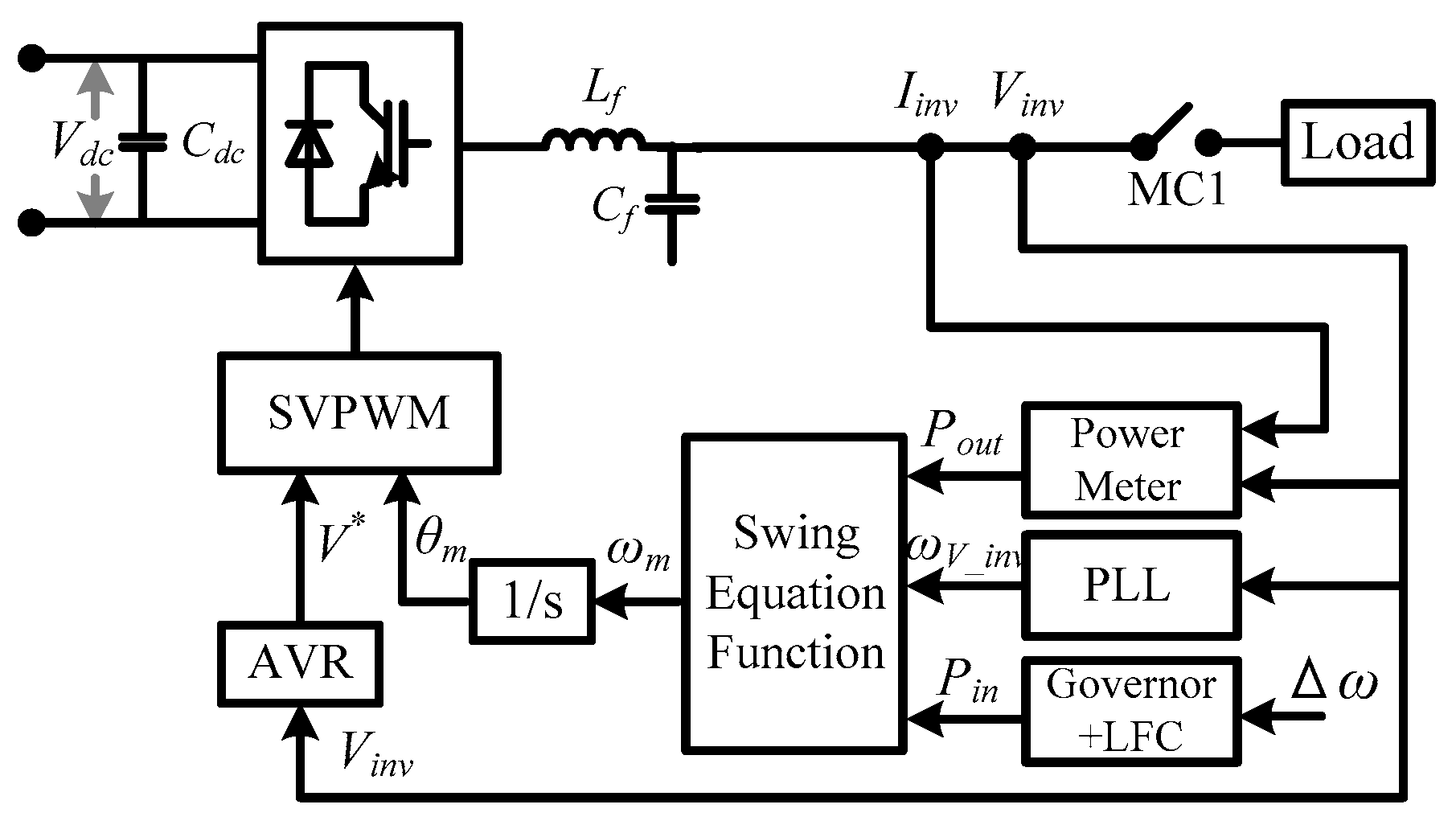
Figure 3.
Block diagram of the automatic voltage regulator (AVR).
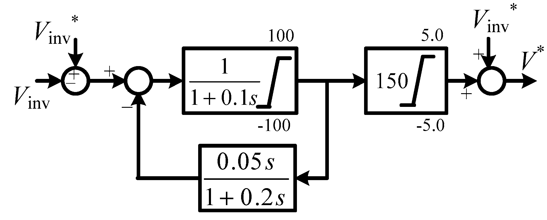
Figure 4.
Block diagram of the governor and the load frequency control.

Figure 5.
Constant stator voltage (CSV) control scheme for the permanent magnet synchronous generator (PMSG) side converter.
Figure 5.
Constant stator voltage (CSV) control scheme for the permanent magnet synchronous generator (PMSG) side converter.
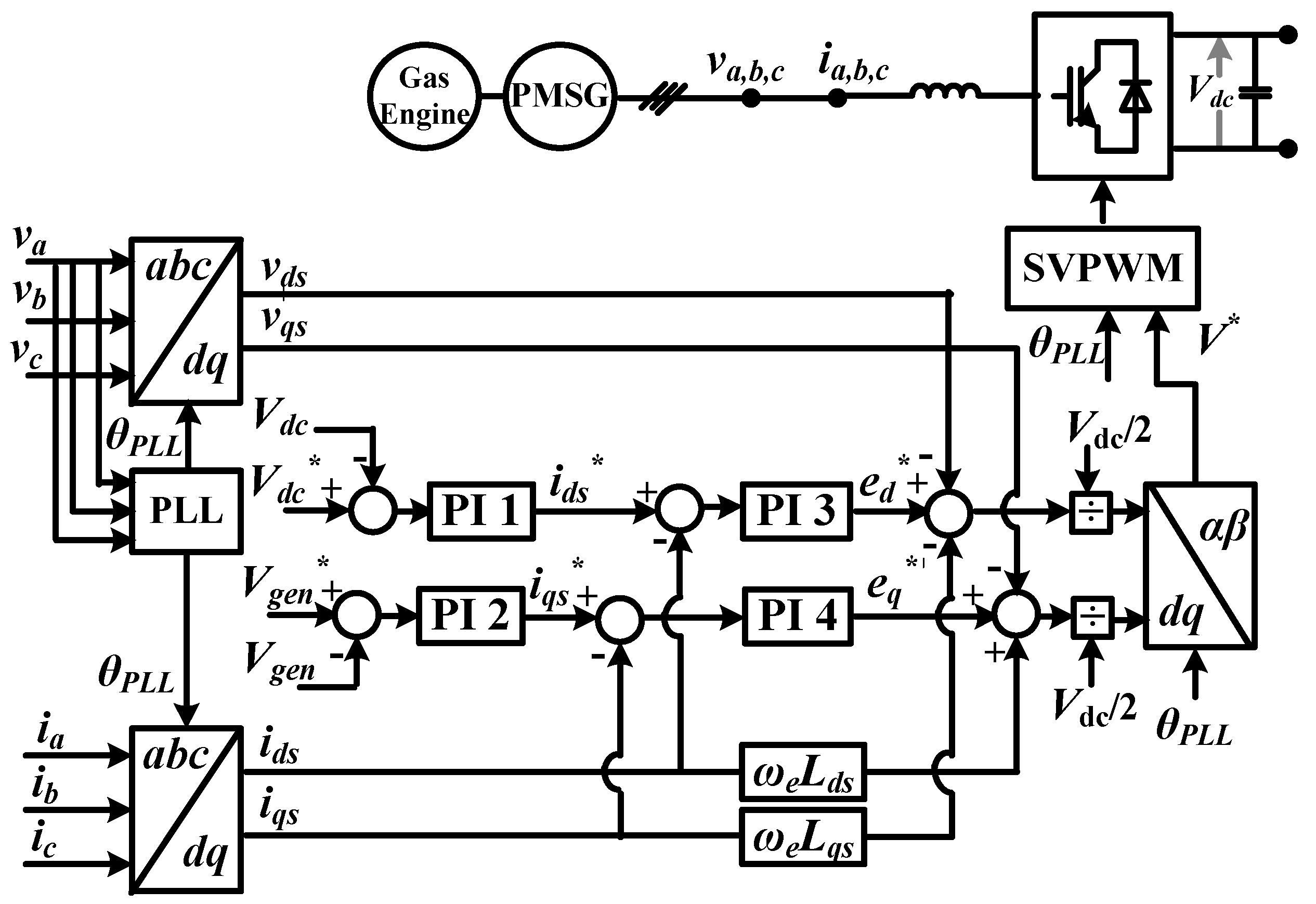
Figure 6.
Circuit configuration used in the simulations.
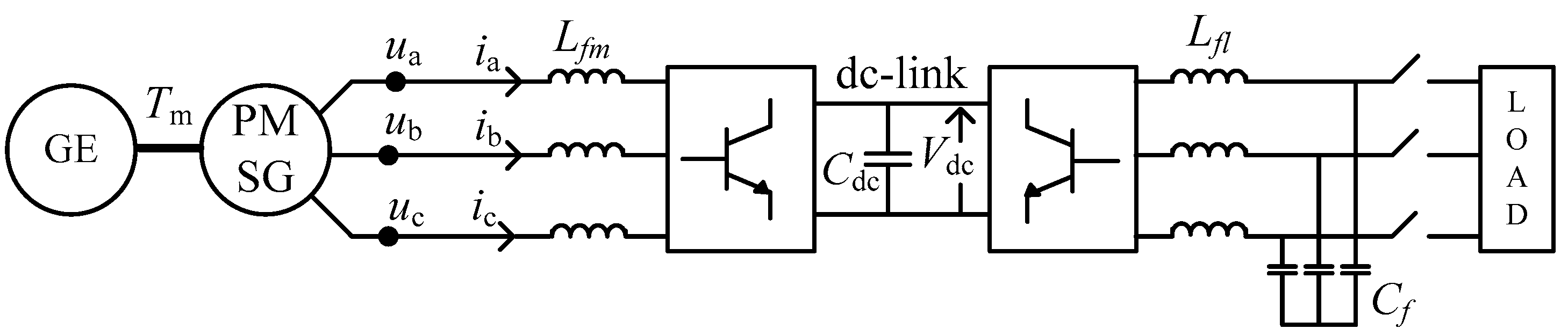
Figure 7.
Speed controller of the gas engine.
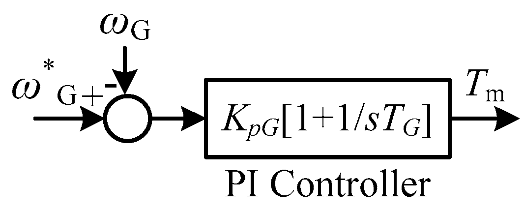
Figure 8.
Waveforms of the generator stator current in steady state (phase a).
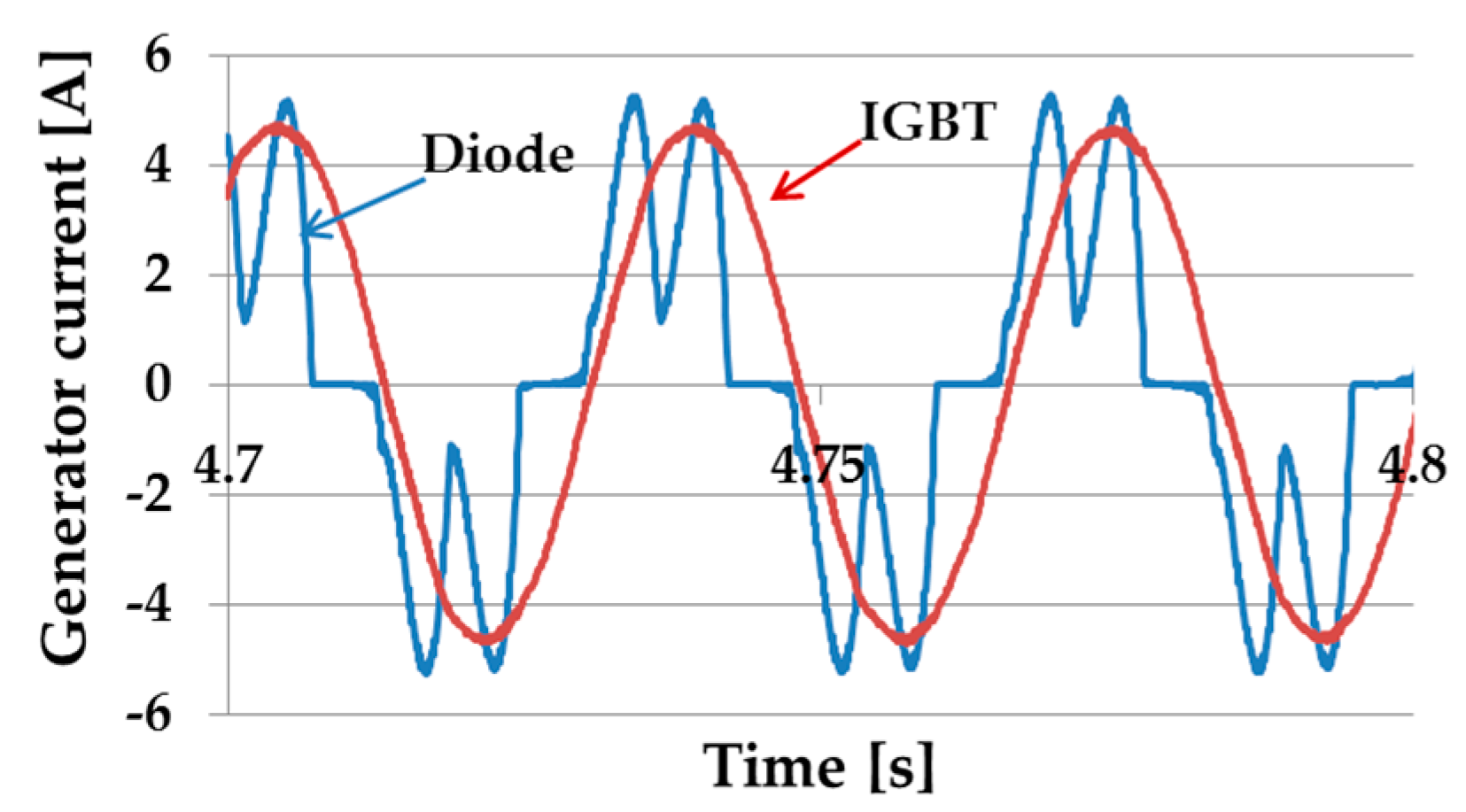
Figure 9.
Results of the engine speed (a) loading case, (b) load removal case.
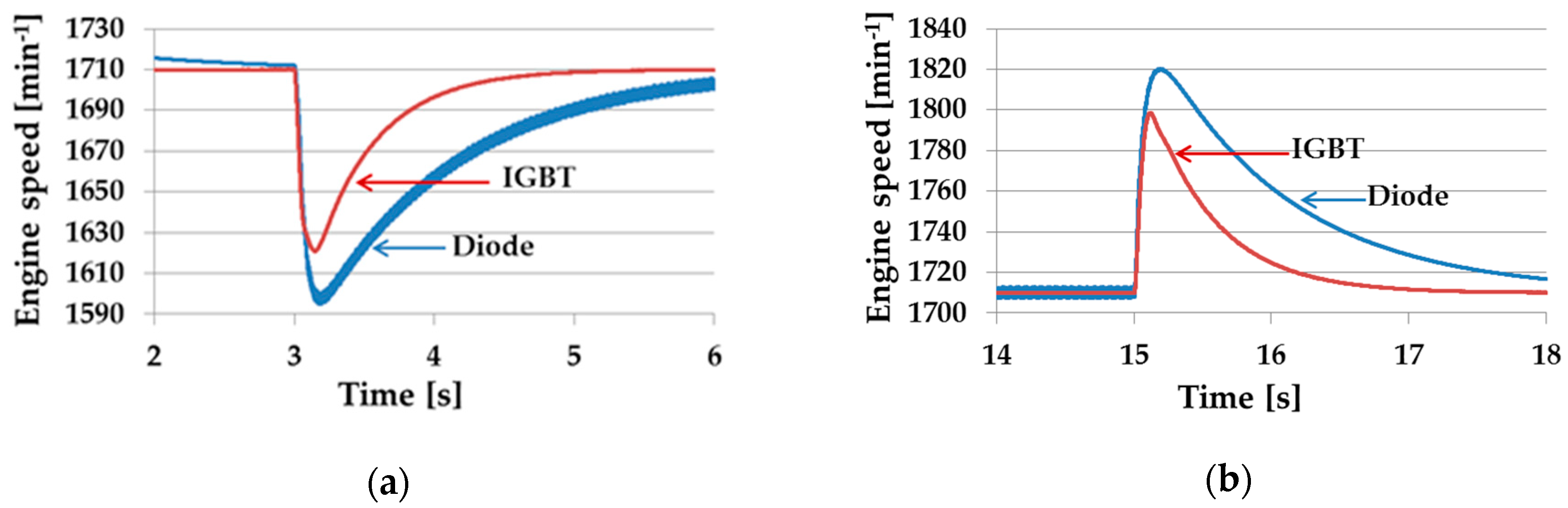
Figure 10.
Results of the stator voltage (a) loading case, (b) load removal case.

Figure 11.
Results of the dc link voltage (a) loading case, (b) load removal case.

Figure 12.
Results of the generator output active power (a) loading case, (b) load removal case.
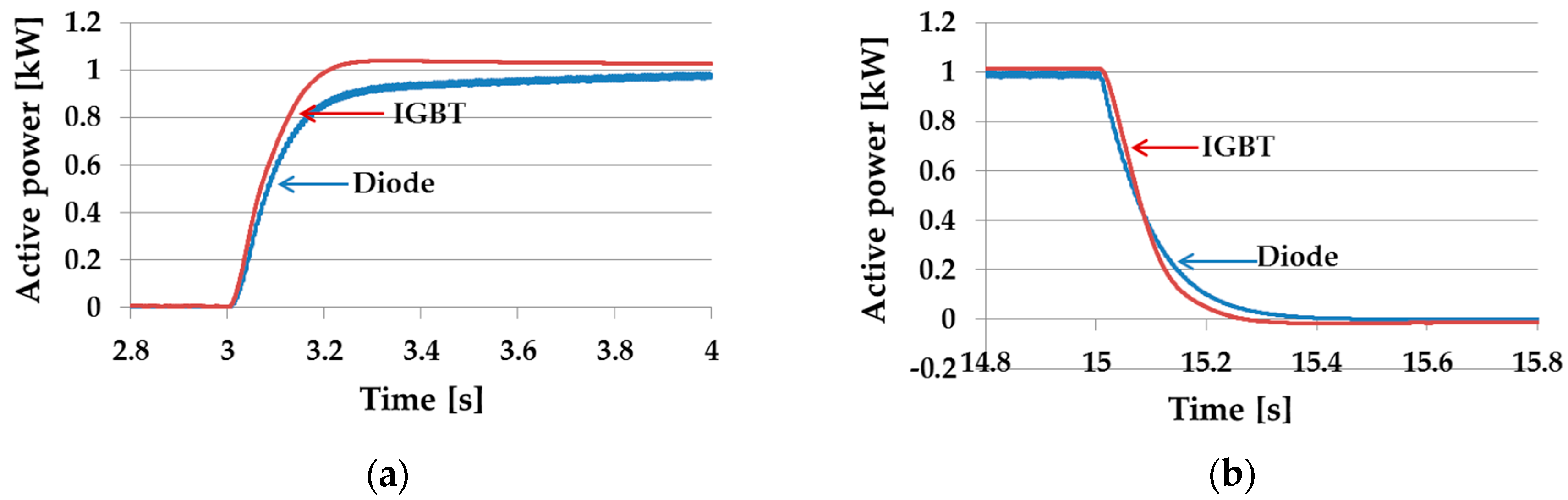
Figure 13.
Results of the inverter output active power (a) loading case, (b) load removal case.

Figure 14.
Control structure with the zero d-axis control (ZDC) control in the PMSG side converter.
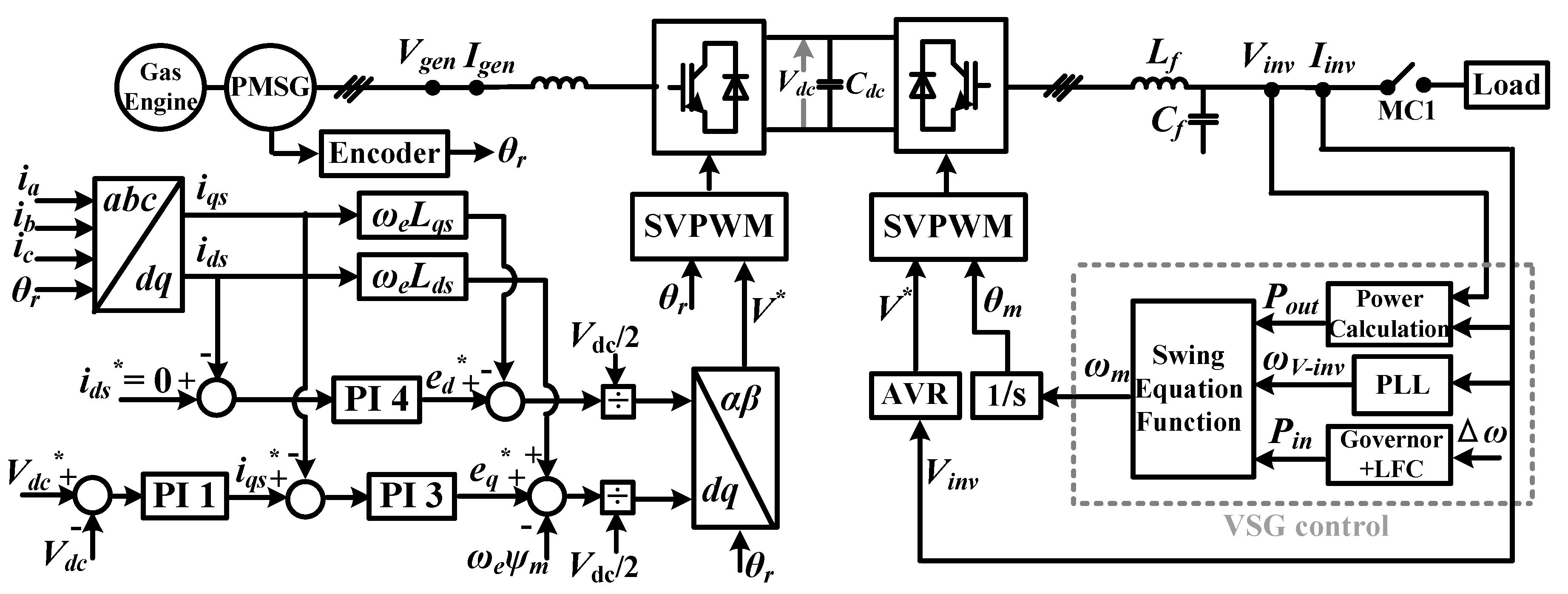
Figure 15.
Control structure with the unity power factor (UPF) control in the PMSG side converter.
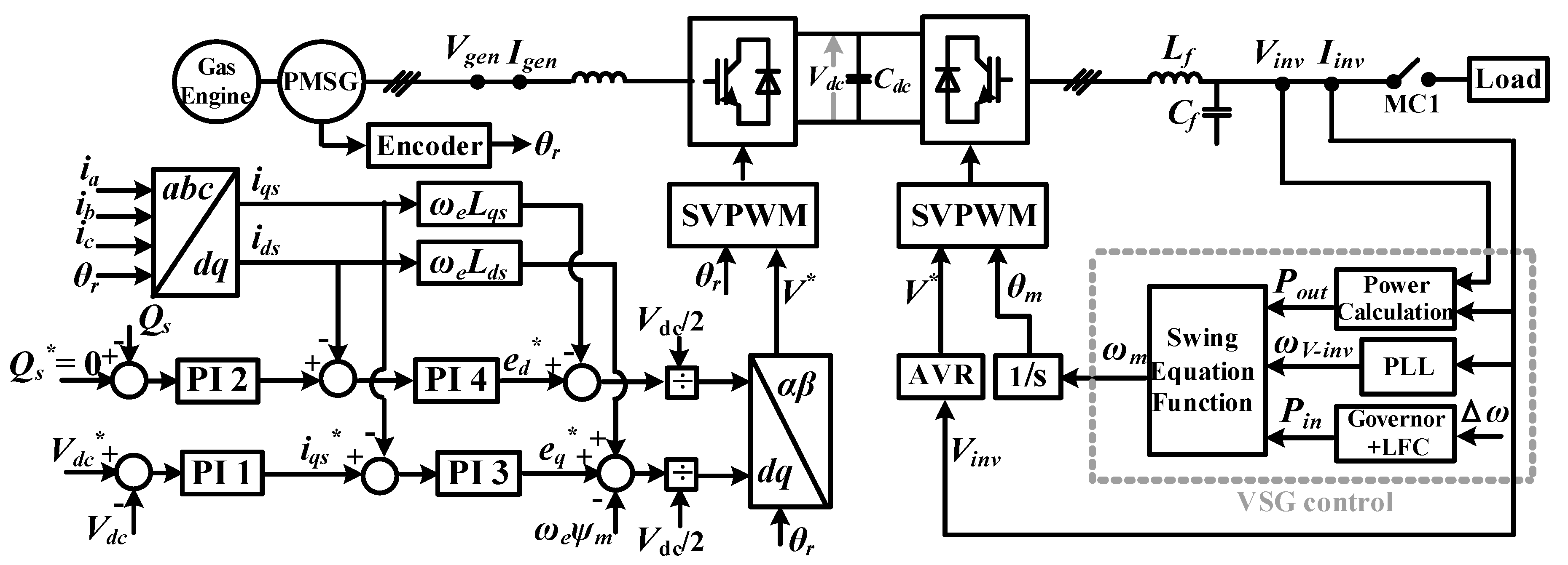
Figure 16.
Results of the engine speed (a) loading case, (b) load removal case.
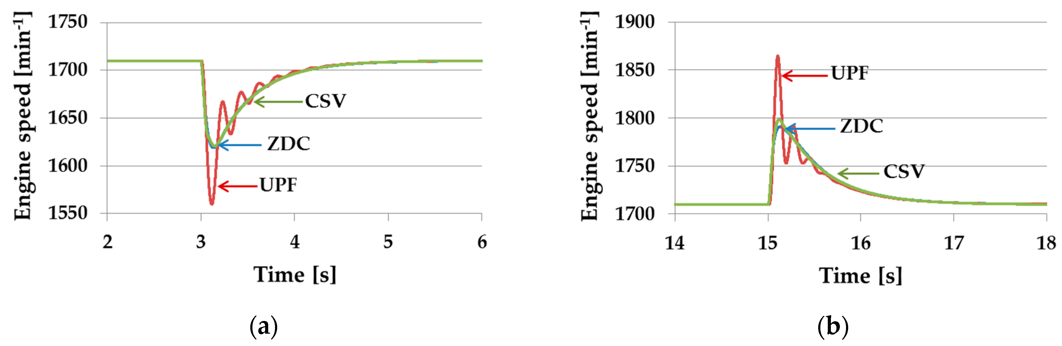
Figure 17.
Results of the stator voltage (a) loading case, (b) load removal case.

Figure 18.
Results of the dc link voltage (a) loading case, (b) load removal case.
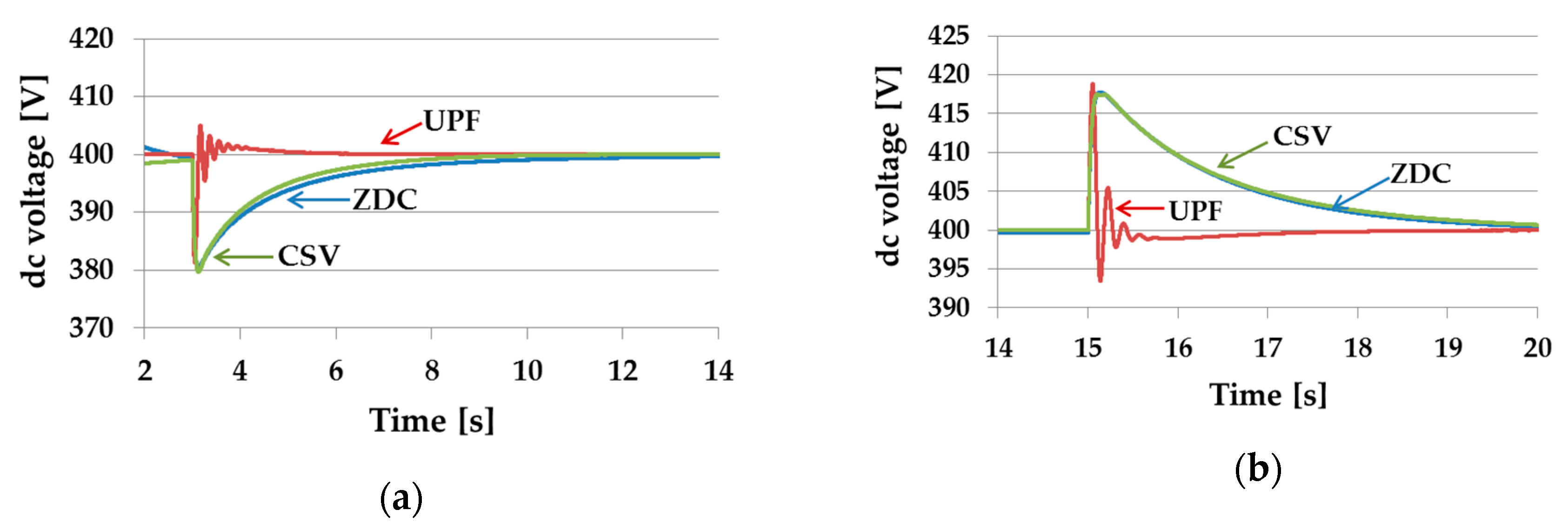
Figure 19.
Results of the generator output active power (a) loading case, (b) load removal case.

Figure 20.
Results of the generator output reactive power (a) loading case, (b) load removal case.

Figure 21.
Results of the inverter output active power (a) loading case, (b) load removal case.


Table 1.
Parameters of the PMSG.
| Xd | 0.219 pu | Xq | 0.219 pu |
| Xd′ | 0.027 pu | Xq′ | 0.027 pu |
| Tdo′ | 6.55 s | Tqo′ | 0.85 s |
| Xd″ | 0.01 pu | Xq″ | 0.01 pu |
| Tdo″ | 0.039 pu | Tqo″ | 0.071 pu |
| Base power | 2 kW | Base voltage | 200 V |
| Engine speed command ωSG* | 1710 min−1 | Per-unit inertia constant | 0.08 s |
| Speed control PI gain kpG | 0.035 | Speed control PI time constant TG | 1.0 s |
Table 2.
Parameters of the VSG control.
| Base Power Pbase | 10 kW | Base Voltage V | 200 V |
| Base Frequency finv_0 | 60 Hz | Speed regulation factor δ | 5% |
| Per-unit inertia constant M | 10 s | Inertia moment J | 0.7036 kg·m2 |
| Damping Factor D | 17 pu | Switching frequency fs | 15 kHz |
| LFC PI gain | 20 | LFC PI time constant | 0.5 s |
| Inverter reference voltage Vinv* | 200 V |
Table 3.
Circuit parameters and proportional integral (PI) control parameters.
| Lfm | 2 mH | Lfl | 1 mH |
| Cdc | 4.7 mF | Cfl | 10 μF |
| Vdc* | 400 V | Vgen* | 200 V |
| Kp of PI 1 | 0.3 | Kp of PI 3 | 50 |
| Ti of PI 1 | 5 | Ti of PI 3 | 0.01 |
| Kp of PI 2 | 0.1 | Kp of PI 4 | 0.3 |
| Ti of PI 2 | 1 | Ti of PI 4 | 0.01 |
© 2020 by the authors. Licensee MDPI, Basel, Switzerland. This article is an open access article distributed under the terms and conditions of the Creative Commons Attribution (CC BY) license (http://creativecommons.org/licenses/by/4.0/).
Share and Cite
MDPI and ACS Style
Hlaing, H.S.; Liu, J.; Bevrani, H.; Ise, T. PMSG Control for a Stand-Alone Gas Engine Generator Using Active Rectifier and VSG-Controlled Inverter. Energies 2020, 13, 233. https://doi.org/10.3390/en13010233
AMA Style
Hlaing HS, Liu J, Bevrani H, Ise T. PMSG Control for a Stand-Alone Gas Engine Generator Using Active Rectifier and VSG-Controlled Inverter. Energies. 2020; 13(1):233. https://doi.org/10.3390/en13010233
Chicago/Turabian StyleHlaing, Htar Su, Jia Liu, Hassan Bevrani, and Toshifumi Ise. 2020. "PMSG Control for a Stand-Alone Gas Engine Generator Using Active Rectifier and VSG-Controlled Inverter" Energies 13, no. 1: 233. https://doi.org/10.3390/en13010233
Note that from the first issue of 2016, this journal uses article numbers instead of page numbers. See further details here.