Design of a Multi-Robot System for Wind Turbine Maintenance


1
MASKOR Institute, Faculty of Mechanical Engineering and Mechatronics, University of Applied Sciences Aachen, 52074 Aachen, Germany
2
Faculty of Engineering and the Built Environment, Tshwane University of Technology, Pretoria 0001, South Africa
*
Author to whom correspondence should be addressed.
Energies 2020, 13(10), 2552; https://doi.org/10.3390/en13102552
Submission received: 14 April 2020
/
Revised: 8 May 2020
/
Accepted: 12 May 2020
/
Published: 18 May 2020
(This article belongs to the Special Issue Maintenance Management of Wind Turbines)
Abstract
:The maintenance of wind turbines is of growing importance considering the transition to renewable energy. This paper presents a multi-robot-approach for automated wind turbine maintenance including a novel climbing robot. Currently, wind turbine maintenance remains a manual task, which is monotonous, dangerous, and also physically demanding due to the large scale of wind turbines. Technical climbers are required to work at significant heights, even in bad weather conditions. Furthermore, a skilled labor force with sufficient knowledge in repairing fiber composite material is rare. Autonomous mobile systems enable the digitization of the maintenance process. They can be designed for weather-independent operations. This work contributes to the development and experimental validation of a maintenance system consisting of multiple robotic platforms for a variety of tasks, such as wind turbine tower and rotor blade service. In this work, multicopters with vision and LiDAR sensors for global inspection are used to guide slower climbing robots. Light-weight magnetic climbers with surface contact were used to analyze structure parts with non-destructive inspection methods and to locally repair smaller defects. Localization was enabled by adapting odometry for conical-shaped surfaces considering additional navigation sensors. Magnets were suitable for steel towers to clamp onto the surface. A friction-based climbing ring robot (SMART— Scanning, Monitoring, Analyzing, Repair and Transportation) completed the set-up for higher payload. The maintenance period could be extended by using weather-proofed maintenance robots. The multi-robot-system was running the Robot Operating System (ROS). Additionally, first steps towards machine learning would enable maintenance staff to use pattern classification for fault diagnosis in order to operate safely from the ground in the future.
1. Introduction
More than 400,000 turbines with a total output power of almost 600 GW are installed globally [1]. Wind turbines are gaining worldwide importance for sustainable power supply. Wind turbine (WT) technology is still relatively young compared to fossil and nuclear power plants. Annual maintenance of wind turbines is required, increasing the total cost of ownership and influencing the competitiveness of their operation with the established power generation. The mechanical components of wind turbines, such as the main shaft, bearings, generator, and gearboxes have evolved. On the other hand, structure parts, such as towers and rotor blades, still need regular and intense maintenance [2]. Access for maintenance is problematic due to challenging weather conditions and the large dimension of wind turbines [3]. Driven by high maintenance demands, various technical solutions with different limitations, costs, and capabilities have emerged. Maintenance requires inspections every second year, including repair based on the inspection results [2]. Inspection and monitoring can be accomplished using high-resolution vision sensors, even from a distance, e.g., ground-based or airborne. However, repairs require direct access to the area of interest. State-of-the-art solutions are industrial climbers and rope-based service frames for any individual type of wind turbine. Common drawbacks are limited payload, inadequate modern measurement technologies to detect failures, and insufficient repair tools, thus confronting service companies with the most expensive alternative, e.g., installing a completely new rotor-blade.
Standard service is restricted to daytime hours, temperatures above 10 °C, a relatively low air humidity, and wind speeds not exceeding the range of 8–12 m/s [3]. All the environmental conditions have to be considered to provide stable conditions and ensure human safety. These conditions restrict the maintenance period to seven months per year and four to six hours per day. Even under stable environmental conditions, repairs remain a delicate task that require expert knowledge, as well as a degree of comfort in working at height. The set-up of such a system takes up to three hours. It has to be reinstalled every day due to general restrictions. Time frames for maintenance are tight, hence methods for efficient documentation, e.g., by monitoring the current position of the repair unit in tower coordinates for quality management, present another challenge.
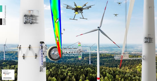
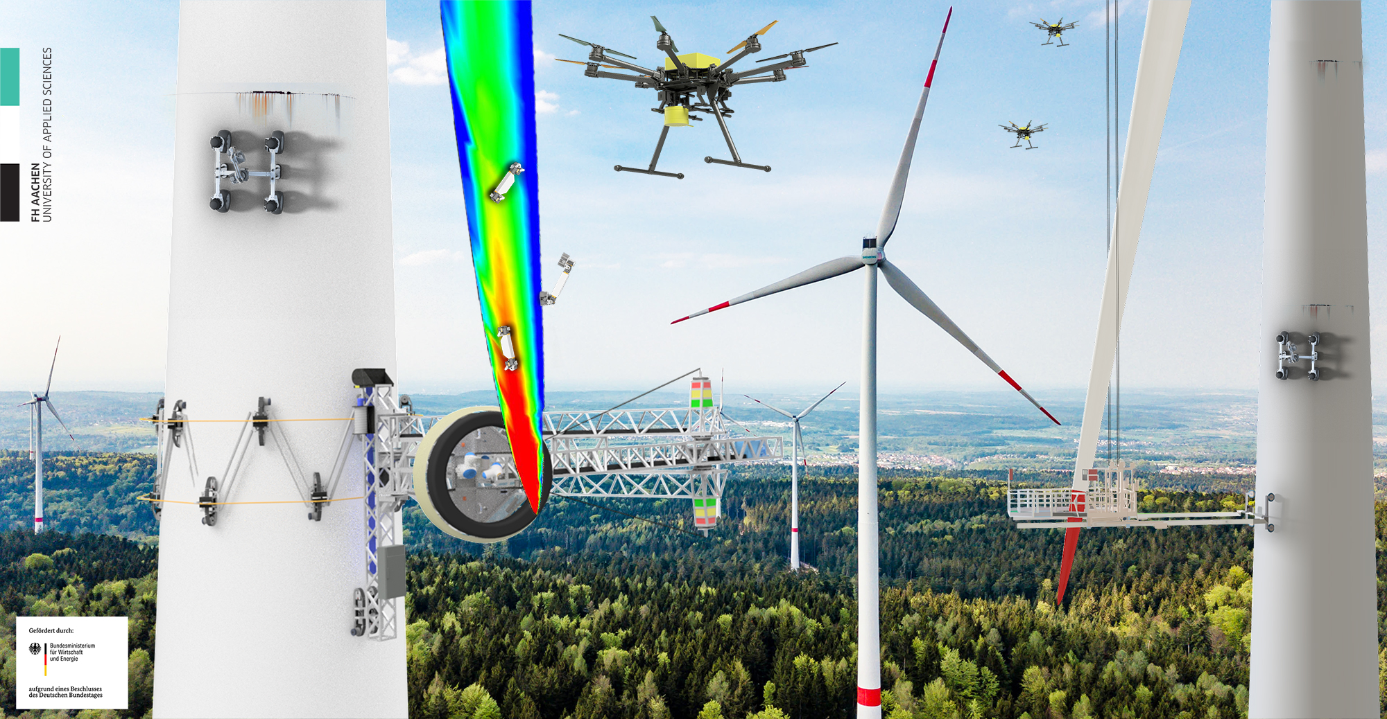
Robots can be used to keep humans safe and improve maintenance quality. Digital twins can be derived from sensor data to enable predictive maintenance and long-term condition monitoring. The first step towards this goal is to develop several prototypes to validate the basics [4,5,6,7]. Flying and surface climbing systems are collaborating with the goal of large-scale inspection in wind farms and on-demand local repairs (Figure 1, Video S1). A friction-based climbing ring robot (SMART: Scanning, Monitoring, Analyzing, Repair and Transportation) can carry high payloads and is equipped with an onboard robotic arm. The SMART robot clasps the tower surface and climbs up and down with friction-based crawlers (Figure 2). Multicopters detect surface damage with vision sensors from a safe distance, even during wind turbine operation. All sensor data is referenced to a global coordinate frame; thus, localization, navigation, and mapping are of major importance. Each mobile system relies on an RTK-GPS for high positioning accuracy. Today, RTK correction signals are not available in every region, so it is still recommended to provide base stations in the wind farm to correct the GPS uncertainty.
Smaller climbing robots carry out non-destructive testing tools, such as ultrasonic and radar with surface contact. Unlike the climbing ring robot, these systems rely on magnetic forces. These robots are faster and easier to install. In general, non-autonomous magnetic climbing robots have reached a high technology readiness level [8,9,10,11] and have been utilized in teleoperation mode on wind turbines for over a decade. This work supports the existing designs with a model-based odometry for conical-shaped wind turbine towers to increase the localization quality and thus the level of automation.
2. Climbing Ring Robot
The central robot of the multi-robot approach is the climbing ring robot (CRR), also known as SMART (Scanning, Monitoring, Analyzing, Repair and Transportation) [6]. The semi-autonomous mobile robot platform serves as a carrier for a weather-independent maintenance cabin with an industrial robotic arm inside. Figure 2 shows the final design. The CRR climbs on the tower surface while clasping the tower to increase stabilization during challenging weather conditions.
The CRR concept consists of three subsystems: locomotion, adhesion, and manipulation. The locomotion unit has two degrees of freedom (DOFs) and is able to rotate around the tower as well as move up and down along the tower axis. Therefore, multiple tracked-wheel crawlers with steering actuators are placed around the tower. A linear actuator for steering is implemented, because skid-steering on wind turbine surfaces leads to severe problems. Due to the convex shape, each crawler is fixed in an upright position and the mandatory slip for skid-steering is prevented by contracting forces [12].
This novel approach for climbing on towers relies on a four-joint gearing mechanism that connects all crawlers to combine their lifting forces. Tension straps contract the climbing ring and apply high normal forces in the radial direction from each crawler to the tower. The friction-based principle provides the highest flexibility to climb either on steel or concrete structures. The mechanism of the adhesion unit needs to adjust to different diameters to cover wind turbine towers with a conical shape. Another purpose of the connection gear is to enable an automated, efficient installation process. The purpose of this rotor blade maintenance platform is to act as a macro-manipulator with three DOFs in the vertical direction for an industrial robot arm inside a weatherproof cabin.
2.1. Material and Methods
The development process is based on several initial models on a smaller scale of 1:20. These design studies include basic functionality and provide sensor feedback for experimental investigations of the kinematics. In addition, simulation results are validated at an early stage of research. All 1:20 models operate on cylindrical shaped towers without conicity due to simplification. Thus, no mechanism for changing the diameter was implemented and the challenge of buffering ropes, belts, or any kinematic was neglected.
The initial model for the climbing principle with belts (Figure 3a) showed the negative influences of belt stretching. This made the climbing robot move downwards after each contraction and release cycle. Consequently, the development of intermittent lifting strokes was discontinued [7].
Subsequently, Lego bricks supported the rapid transition towards crawlers (Figure 3b), thus introducing continuous climbing instead of intermittent climbing. An initial test indicated that the lifting force from one crawler to another can be transferred with a rigid connection. First, diagonal ropes were employed for the connection, while rubber bands contracted the system. For the third model (Figure 3c), the ropes were replaced with “Nuernberger” scissors. At this point, a fully functional demonstrator at 1:3 scale was derived for further research and investigation. Another iteration (Figure 3d) led to the final concept of this work, which will be presented in the following subsections. The final concept was finally validated with a 1:3 demonstrator before the large-scale prototype was designed and tested on a conical-shaped tower for the first time.
Within the project, two systems at 1:3 scale were developed and intensively tested [5]. The crawler concept and materials were quite similar. The kinematic design has evolved and enabled a total system weight reduction of 50% from 800 to 400 kg, including the control cabinet, which was put on the ground in the previous concept (Figure 4a). The surface contact area and the combined lifting force of all 18 crawlers remained the same. Due to the novel arrangement of the crawlers, their contribution to lifting the main body increased. As part of the adhesion system, the horizontal cross connection fulfills the function of transmitting lifting forces from all crawlers to the mainframe.
The final CRR concept consists of 18 crawlers(Figure 4b), Figure 5 (1) which are coupled by a four-joint kinematic (2) and two installation racks (3) as main frames. The system is divided into two parts: seven to nine crawlers are mounted on each installation frame (Figure 11). Positioning linear actuators (2) are located in the center of the four-joint kinematic to keep the crawler in a horizontal position during the installation process. Retractable air bellow spacers (4) at the upper end of the frame support the robot on the tower during the installation process. The crawler tracks are in frictional contact with the tower. Harmonic drives (at scale 1:3 CHA-20A-160, 90 Nm; at scale 1:1 CHA-40A-160, 600 Nm) provide high torque for climbing, and have a compact design. Wire ropes are attached to the crawlers and tensioned by eight winches (7), generating the required normal force. The crawlers are pressed radially against the tower. The control system, consisting of switch cabinet (5), motor controller (8), and power supply (6) are located on the installation frames, so that no further external devices are required. A cable connects the robot’s power supply units to the main supply.
2.2. Mechanical Design
The first approach (Figure 4a) employed the concept of multiple “Nuernberger” scissors. However, finite element method (FEM) simulation indicated that a lightweight four-joint kinematic is more efficient, which was substituted for the former concept in the second approach (Figure 4b). The CRR can utilize the four-joint connections not only for transmitting the lifting forces of each individual crawler, but the actuated kinematics can also be used to support the installation process (Section 2.5).
Based on prototype parameters and size, Table 1 compares the two cross-connection concepts in favor of the four-joint kinematic. The downside of the new approach is that the pairs of crawlers that are required for steering left and right have to be split up, and thus the connection between the climbing system and adhesion system demands additional degrees of freedom (DOFs).
One DOF for steering is implemented in the center of the crawler with an IGUS disc bearing. Two synchronized linear actuators push and pull simultaneously and rotate the red part of the crawler frame vs. the black coupling towards the horizontal connection. The steering angle α is measured with an absolute rotational encoder in the center of the motion. It is mandatory to drive forward during the steering motion due to the high friction (Figure 6).
A bolt bearing below the steering kinematic enables the tilt motion β for conical-shaped wind turbine towers. The horizontal connection is orientated vertically to the ground in any situation. Each crawler has to align itself to the surface. This DOF is not actuated. The total lifting force FL and the normal force FN are measured with a bi-directional load bolt in the center of the bearing (Figure 7). These forces are monitored to ensure balanced ascending and descending.
The third DOF disables the uneven contraction and expansion of the tensioning system. Thus, the black connectors to the horizontal connection can move around a vertical axis but a gear mechanism keeps both angles γ the same. Otherwise, the alignment of all grasping angles would be different. The steering motion is controlled individually, so the distance between each individual crawler may vary during the climbing process, due to slip-stick effects. Even small variations can cause a mismatch of the grasping angles. To prevent internal mechanical stress this DOF is restricted (Figure 8). Figure 8 also illustrates the measurement of the rope force to control the winches.
The scaling of the CRR design was supported by the generation of a kinematic model in ADAMS multibody simulation software (MBS, Figure 9). The kinematics of the demonstrator are simulated and experimentally validated with the measurements outlined above:
- Drive torque MDrive,
- normal force FN,
- lifting force FL,
- rope tension FRope.
The MBS software was used to test different designs and concepts. Furthermore, the simulation served for estimating the forces and torques of the prototype to support the design phase. Figure 9a presents a generated model. Figure 9b outlines the distribution of the simulated normal forces in the static state of the CRR with the adhesion system switched on. Finally, Figure 9c transitions to the next set-up of simulations on a conical-shaped tower.
The simulation of the crawler tracks was carried out with the ADAMS Tracked Vehicle Module (ATV). The analysis in ATV indicates that belt-based crawler tracks load the curved tower surface unevenly [4]. Comparative investigations have shown that with disc tracks a uniform distribution of the local surface pressure is achievable. Elastomer profiles are mounted on the disc track and may be changed with regard to friction and damping properties. The experimental validation quantified the forces without (Figure 10a) and with an attached cantilever arm (Figure 10b). Thus, the torque of all crawlers was raised to a maximum. In particular, crawlers 2, 15, 10, and 16 utilized higher torque due to the higher normal force resulting from the tilting moment of the cantilever arm (Figure 11). Further data analyses might overload this comprehensive report. Therefore, this example was selected to illustrate the general method of development. Based on the data validation the simulated MBS models were improved.
2.3. Friction Testing
The system was designed considering the fragility of wind turbine towers—consisting of thin steel structures with large diameters—towards perpendicular forces. To reduce these perpendicular forces a high friction coefficient is mandatory. The coefficient describes the relationship between normal and lifting forces and has a major impact on the feasibility of the CRR in terms of total payload. A friction test bench was developed for the prototype to determine the:
- coefficient of friction between crawler and tower surface,
- the steering force of the linear actuators,
- the ratio between motor torque and normal force (rolling friction) under real conditions.
A prototype 1:1 scaled crawler (Figure 12(7)) was used for the final tests. The friction test rig consists of a welded steel frame (1) with a bolted steel plate (2). The steel plate is coated according to DIN EN ISO 12944—corrosion protection class C5—similar to the tower surface of a wind turbine. The normal force FN is generated by the rope force FRope. The rope is tensioned by two suspension eyes (6) over deflection rollers (behind cover) of the trolley (8). The rope force is measured with a load cell (5). An electric motor generates the pulling force FZ employing a trapezoidal thread spindle 14 × 7 (3). The pulling force is measured with a load cell (4). The spindle pulls the crawler over the steel plate while the rope is tensioned and breaks are activated. The quotient between the measured forces FZ and FN results in the coefficient of friction µ [13,14].
To determine the coefficient of friction, different surface conditions are examined: dry, icy, oily, and wet. These simulate possible weather and climbing scenarios. The following Table 2 provides the minimal values after five repetitions for different surface parameters for reference.
The table indicates that NBR is a suitable rubber material with the best friction properties. The coefficients of friction of all types are similar, especially on sandy surfaces. The highest deviation occurs on dry surfaces, which is the standard environment for wind turbines. Therefore, EPDM was selected for the initial proof-of-concept. It should be mentioned that EPDM showed a distinctive slip-stick effect that causes the testing material to jump small distances instead of a linear sliding motion. Nevertheless, this effect only occurs in a non-static friction state, which is prevented by the contracting system. All crawler tracks are equipped with adhesive disks made of EPDM rubber (Shore hardness 40). The coefficient of friction between rubber and tower surface was estimated by µmin = 0.8 for the testing conditions. The coefficient is never a constant in real world applications. Nevertheless, a final product must be designed for a friction coefficient of 0.3 (icy and oily) and appropriate safety factors. The prototype design considers a significantly higher coefficient due to the fact that it is designed for testing, which results in a higher total system weight.
2.4. Proof-of-Concept
In the accomplishment of the full development process, a real size prototype served as the final proof of concept in 2019 (Figure 13a). Due to safety regulations, a simplified testing scenario was created on a wind turbine mock-up. The predefined tower size was relatively small with a 3.5 m diagonal. This size limited the 7.2 ton CRR to climb a height of 1.3 m in total before running into contraction limits. Nevertheless, the main functionality of the system was investigated and confirmed, including semi-automated installation, climbing, steering, load distribution, contact surface, navigation, and payload. All systems were designed in accordance to IP 64 standard for outdoor usage. The mobile climbing ring robot included the cantilever arm (macro manipulation) and the industrial robot arm (micro manipulation) inside the cabin, which were utilized on a rotor blade part nearby. The industrial robot arm could be teleoperated based on the Robot Operating System (ROS) [15]. The prototype was equipped with sensors, such as RGB cameras and LiDAR, to observe the working environment and to measure the surface geometry of the blade. A digital twin with a 3D surface scan and texture was matched by point-cloud library fusion algorithms. ROS was used to calculate the reverse kinematics of the cantilever for a simplified robot control by height and angle. Thus, using ROS enabled reaching the full potential of this mobile manipulator. Existing approaches for perception, localization, and collision-free path planning, together with hardware independence, created a suitable environment for future work.
2.5. Installation Process of the CRR
The developed process takes the door to enter the wind turbine tower into account and includes a lifting system to contract the climbing ring above the average door height of 3.5 m. The two installation racks including the crawlers were installed with an offset of approx. 180° and 90° towards the door on the tower surface. The CRR was placed with a small truck crane. The weight of the segments was approx. 2.5 tons. After the placement of the installation racks, they were fixed with belts to the tower. One tensioning belt was placed around the installation racks at the top and bottom and around the tower, then tightened. The installation racks were pressed against the tower surface. At this point, the crawlers facing the tower surface did not yet have any contact with the tower (Figure 14a).
In the second step, the crawlers of both installation racks were guided around the tower and connected together. For this purpose, diagonal actuators in the four-joint kinematic were actuated hydraulically. These cylinders were all subjected to tensile stress, so that buckling was avoided. The crawlers still had no contact with the tower and could be checked one last time on the ground(Figure 14b).
The CRR was then lifted over the entrance door using a lifting system between the installation racks and the crawlers. Finally, the tensioning system was tightened synchronously with cable winches. The crawlers were pressed against the tower and all tensioning belts released (Figure 14c). The CRR was ready for operation.
3. Multicopter
For the regular inspection of a WT, a multicopter (Figure 15) is a cost-effective and flexible technical solution compared to the CRR. The unmannend arial vehicle (UAV) shown in Figure 15 was developed for this application and prepared for the test phase of the other prototypes. DJI’s multicopter S1000 served as a platform for the sensor box and the computer. It enabled a climb and descent of the wind turbine with a flight time of 10 min. The sensor box was installed on the lower part of the frame of the S1000.
Deep convolutional neural networks (DCNN) were implemented to detect the corrosion of welding lines on the tower surface [16]. The digital twin of the tower automatically lines the image up with the tower height and angle towards the wind turbine entrance. In addition, all failures are summarized in a standard sheet and transmitted to the WT operator to calculate and conduct the required repairs. Figure 16 presents the implementation with a highlighted region of interest around the horizontal welding lines.
4. Magnetic Climbing Robot
The basic function of the magnetic inspection platform is the positioning of sensors on the vertical tower surface (Figure 17). An omnidirectional approach was finally selected to be able to move on the complete curved plane in all three DOFs [17,18,19,20,21]. The designed magnetic climbing robot (MCR) operates without rotating the mainframe. Only the wheels may change their orientation for steering purposes. A magnet in the center of the mainframe attaches the robot to any steel surface, while a small air gap enables the motion capability.
The movement on the tower surface can be controlled by the following parameters (Figure 18):
- z represents the translation along the tower axis (height, H),
- Ω × represents the translational movement tangentially around the tower combined with a rotation around the tower axis depending on the tower diameter,
- ω is the angular velocity around the normal vector of the tower surface.
4.1. Inverse Kinematics
The inverse kinematics of the robot are used to control the speed and angular velocity of the coordinate system ROBROOT and to derive the individual converted wheel coordinate system RK1 to RK4 (Figure 19). This is necessary to control the steering actuators and the traction motors [22]. Parameters of the inverse kinematic are target speed in the ROBROOT frame; the target angular velocity ω (Equation (6)); the position of the wheels HRK1 to HRK4; the tower geometry, consisting of HRK1 (tower height), rb (radius bottom), and rt (radius top); the position vectors of the robot wheels to ; and the wheel radius . Based on these parameters, the inverse kinematics follow as Equations (1)–(3):
4.2. Model Based Odometry
Odometry refers to the relative estimation of the pose by observing the drive sensors [23]. Odometry forms the basis for the localization of the platform. The localization is based on an integration of the velocity vectors of the forward kinematics over time (dead reckoning). In the implementation, the forward kinematics are calculated for a point in time, the calculated velocity vectors are multiplied by a time period, and the resulting change in position is summed over the total time. The input variables (Figure 20) are the steering angle of each wheel to (Equation (5)) and the speed vectors of each wheel to (Equation (4)).
The accuracy of the odometry affects the uncertainty of the robot’s localization [17,18,19,20,21]. Therefore, as with inverse kinematics, the tower curvature has to be considered. In the following, a model-based odometry for driving conical towers will be presented. The used coordinate system is the cylindrical tower coordinate system. In comparison to the odometry for plane surfaces, first it calculates the rotation of the robot. Then, the speed of the robot is calculated tangentially to the tower surface and along the symmetry axis of the tower. In the conversion of the distance covered by the robot along the y axis of the ROBROOT coordinate system to the symmetry axis of the tower, the angle of the conicity is used:
The model-based odometry relies on the current rotation of the robot, as well as the current height . Both angular velocity (Equation (8)) and vertical velocity (Equation (9)) are converted into absolute positioning data (Equation (10)).
To validate the approach of model-based odometry for conical-shaped wind turbines, two concepts were developed. Concept (Figure 21a) utilizes four wheels with individual steering actuators, while concept (Figure 21b) utilizes only two wheels in means of cost reduction. Only concept (Figure 21a) was validated with a prototype. The advantage is that a robotic manipulator can be mounted to carry out different inspection and repair tasks. System (Figure 21b) has less payload and may only be used for fast inspection.
5. Conclusions and Outlook
A single system does not provide the capability to be an all-in-one replacement for conventional manned access technology. This work presents a multi-robot system that is suitable for many tasks. The multi-robot system enables maintenance staff to control inspection tasks safely from the ground. ROS is implemented for process control, especially for collision-free path planning in unstructured environments, as well as adaptive vision-based control [15]. The Bezier library within ROS provides scanning and path planning functionality for curved surfaces. Based on a 3D surface scan, an optimized tool path was generated that keeps any tool orthogonally on the freeform surface. Industrial robots are suitable manipulators for this task. This environment simplifies the process development of different thermography, radar [24], and ultrasonic applications for surface and structure inspection, as shown in Figure 22a–c, respectively. Figure 22 presents measurements carried out during this research as experimental validation. Figure 22a–c represent the same section of a 12 m rotor blade and show air gaps in a glue pattern, that occurred during the manufacturing process of this blade.
Future steps will include the implementation and test of a wide range of maintenance process tools based on a tool changing system. Inspection results and repair process parameters may be sampled to set up an expert system based on machine learning. A first introduction of this technique was presented with the flying system and visual inspection of welding lines via DCNN.
A future goal is the enrichment of the digital twin for wind turbines and even wind farms. This enables long-term condition monitoring, which helps to carry out predictive maintenance in order to reduce costs and increase operation time.
Furthermore, it is conceivable that several systems equipped with different tools solve the entire process chain in a swarm approach. The simplification of control by angle and height definition based on the inverse kinematics and the derived odometry is the first step towards autonomy. Any maintenance locations, due to the relatively deterministic tower structure, can be defined by height, initial diameter, and conicity. Thus, the foundations have been created to enable a single operator to efficiently control a large number of service robots in a process-oriented manner. This results in a cost advantage for the operator.
Supplementary Materials
The following are available online at https://fh-aachen.sciebo.de/s/zEROadazzhOUeBv, Video S1: Wind Turbine Maintenance with Robotics by MASKOR Institute Aachen.
Author Contributions
Methodology and concepts J.F. and E.D.; supervision, S.K. and S.D.; sensors and software, H.E.; validation and testing, J.F., H.E. and E.D.; writing—original draft preparation, J.F.; project administration, S.K. and P.D.; funding acquisition, J.F. and M.B. All authors have read and agreed to the published version of the manuscript.
Funding
This research was funded by German ministry for economy and energy (BMWi), grant number 5.3 million euro.
Acknowledgments
The research is supported by two industrial project partners: ematec AG and Gbr. Kaeufer GmbH from Germany.
Conflicts of Interest
The funders had no role in the design of the study; in the collection, analyses, or interpretation of data; in the writing of the manuscript, or in the decision to publish the results.
References
- Durstewitz, M.; Guillaume, B.; Berkhout, V.; Buchmann, E.; Cernusko, R.; Faulstich, S.; Hahn, B.; Lutz, M.; Pfaffel, S.; Rehwald, F.; et al. Windenergy Report Germany 2017; Fraunhofer IEE: Kassel, Germany, 2018; pp. 19–21. [Google Scholar]
- Rehfeld, K.; Wallasch, A.; Luers, S. Cost Situation of Onshore Wind Energy in Germany; Report by German Windguard; 2015; Available online: https://www.windguard.de/veroeffentlichungen.html (accessed on 13 May 2020).
- Paulsen, T.; Thuering, H.; Fries, D. Windenergy Service—Maintenance and Repair; Bundesverband Windenergie, BWE: Berlin, Germany, 2012. [Google Scholar]
- Schleupen, J.; Engemann, H.; Bagheri, M.; Kallweit, S.; Dahmann, P. Developing a climbing maintenance robot for tower and rotor blade service of wind turbines. In Proceedings of the International Conference on Robotics in Alpe-Adria-Danube Region—RAAD 2016, Belgrad, Serbia, 30 June–2 July 2016. [Google Scholar]
- Schleupen, J.; Engemann, H.; Bagheri, M.; Kallweit, S. The potential of SMART climbing robot combined with a weatherproof cabin for rotor blade maintenance. In Proceedings of the 17th European Conference on Composite Materials—ECCM, Munich, Germany, 26–30 June 2016. [Google Scholar]
- Kallweit, S.; Dahmann, P.; Bagheri, M.; Schleupen, J.; Engemann, H. Development of a climbing-robot for diagnose and maintenance of wind turbines. In Proceedings of the 13th Applied Automation Technology in Education and Development—AALE, Luebeck, Germany, 1 March 2016. [Google Scholar]
- Bagheri, M.; Schleupen, J.; Dahmann, P.; Kallweit, S. A multi-functional device applying for the safe maintenance at high-altitude on wind turbines. In Proceedings of the 20th International Conference on Composite Materials—ICCM20, Copenhagen, Denmark, 19–24 July 2015. [Google Scholar]
- Rafael, A.; Saltarén, R.; Reinoso, O. A climbing parallel robot: A robot to climb along tubular and metallic structures. IEEE Robot. Autom. Mag. 2006, 13, 16–22. [Google Scholar]
- Rafael, A.; Saltarén, R.; Reinoso, O. Parallel robots for autonomous climbing along tubular structures. Robot. Auton. Syst. 2003, 42, 125–134. [Google Scholar]
- Hayashi, S.; Takei, T.; Hamamura, K.; Ito, S.; Kanawa, D.; Imanishi, E.; Yamauchi, Y. Moving mechanism for a wind turbine blade inspection and repair robot. In Proceedings of the 2017 IEEE/SICE International Symposium on System Integration (SII), Taipei, Taiwan, 11–14 December 2017. [Google Scholar]
- Waldron, K.J.; Sattar, T.P.; Rodriguez, H.L.; Bridge, B. Climbing ring robot for inspection of offshore wind turbines. Ind. Robot Int. J. 2009, 36, 326–330. [Google Scholar]
- Morales, J.; Martinez, J.L.; Mandow, A.; Garcia-Cerezo, A.J.; Pedraza, S. Power consumption modeling of skid-steer tracked mobile robots on rigid terrain. IEEE Trans. Robot. 2009, 25, 1098–1108. [Google Scholar] [CrossRef]
- Czichos, H.; Habig, K. Tribologie-Handbuch, 3rd ed.; Vieweg + Teubner: Wiesbaden, Germany, 2010; p. 85. [Google Scholar]
- Lahayne, O.; Pichler, B.; Reihsner, R.; Eberhardsteiner, J.; Suh, J.; Kim, D.; Nam, S.; Paek, H.; Lorenz, B.; Persson, B.N. Rubber Friction on Ice: Experiments and Modeling; Springer: Berlin, Germany, 2016. [Google Scholar]
- Rosen, E.; Whitney, D.; Phillips, E.; Ullman, D.; Tellex, S. Testing robot teleoperation using a virtual reality interface with ROS reality. In Proceedings of the 1st International Workshop on Virtual, Augmented, and Mixed Reality for HRI (VAM-HRI), Chicago, IL, USA, 5 March 2018. [Google Scholar]
- He, K.; Gkioxari, G.; Dollar, P.; Girshick, R. Mask R-CNN. arXiv 2017. Available online: https://arxiv.org/abs/1703.06870 (accessed on 13 May 2020).
- Tavakoli, M.; Viegas, C.; Marques, L.; Pires, J.N.; de Almeida, A.T. OmniClimber-II: An omnidirectional climbing robot with high maneuverability and flexibility to adapt to non-flat surfaces. In Proceedings of the IEEE International Conference on Robotics and Automation, Karlsruhe, Germany, 6–10 May 2013; pp. 1349–1354. [Google Scholar]
- Zhang, Y.; Dodd, T.; Atallah, K.; Lyne, I. Design and optimization of magnetic wheel for wall and ceiling climbing robot. In Proceedings of the IEEE International Conference on Mechatronics and Automation, Xi’an, China, 4–7 August 2010. [Google Scholar]
- Tâche, F.; Fischer, W.; Caprari, G.; Siegwart, R.; Moser, R.; Mondada, F. Magnebike: A magnetic wheeled robot with high mobility for inspecting complex-shaped structures. J. Field Robot. 2009, 26, 453–476. [Google Scholar] [CrossRef]
- Eich, M.; Vögele, T. Design and control of a lightweight magnetic climbing robot for vessel inspection. In Proceedings of the 19th Mediterranean Conference on Control Automation (MED), Corfu, Greece, 20–23 June 2011; pp. 1200–1205. [Google Scholar]
- Li, J.; Wang, X.S. Novel omnidirectional climbing robot with adjustable magnetic adsorption mechanism. In Proceedings of the 23rd International Conference on Mechatronics and Machine Vision in Practice (M2VIP), Nanjing, China, 28–30 November 2016; pp. 1–5. [Google Scholar]
- Almonacid, M.; Saltaren, R.J.; Aracil, R.; Reinoso, O. Motion planning of a climbing parallel robot. IEEE Trans. Robot. Autom. 2003, 19, 485–489. [Google Scholar] [CrossRef]
- Information Resources Management Association. Robotics: Concepts, Methodologies, Tools, and Applications, 1st ed.; Hershey, P.A., Ed.; IGI Global: Hershey, PA, USA, 2013. [Google Scholar]
- Nowok, S.; Kueppers, S.; Cetinkaya, H.; Schroeder, M.; Herschel, R. Millimeter wave radar for high resolution 3D near field imaging for robotics and security scans. In Proceedings of the 18th International Radar Symposium (IRS), Prague, Czech Republic, 28–30 June 2017; IEEE: Piscataway, NJ, USA, 2017. [Google Scholar]
Figure 1.
Wind farm maintenance vision.

Figure 2.
Climbing ring robot, SMART (Scanning, Monitoring, Analyzing, Repair and Transportation).

Figure 3.
Design studies scaled by 1:20: (a) belt climbing ring robot; (b) Lego based design; (c) crawlers with scissors; (d) final concept.
Figure 3.
Design studies scaled by 1:20: (a) belt climbing ring robot; (b) Lego based design; (c) crawlers with scissors; (d) final concept.

Figure 4.
Climbing ring robot (CRR) demonstrator 2016 (a); CRR demonstrator 2018 (b). Both are scaled by a factor of 1:3 regarding a 2.5 MW wind turbine.
Figure 4.
Climbing ring robot (CRR) demonstrator 2016 (a); CRR demonstrator 2018 (b). Both are scaled by a factor of 1:3 regarding a 2.5 MW wind turbine.

Figure 5.
Climbing ring robot (scaled 1:3).

Figure 6.
Top-view of the CRR crawler; arrows indicate steering axis.

Figure 7.
Side-view of the CRR crawler; arrows indicate the alignment axis for a conical-shaped wind turbine tower.
Figure 7.
Side-view of the CRR crawler; arrows indicate the alignment axis for a conical-shaped wind turbine tower.

Figure 8.
Front-view of the CRR crawler; arrows indicate circular tower alignment.

Figure 9.
ADAMS Multi-Body-Dynamic Simulation: radial forces on the tower surface in top-view (a); radial forces side-view (b); set-up on a conical-shaped tower (c).
Figure 9.
ADAMS Multi-Body-Dynamic Simulation: radial forces on the tower surface in top-view (a); radial forces side-view (b); set-up on a conical-shaped tower (c).

Figure 10.
Experimental data from CCR: without cantilever arm (a); with cantilever arm (b).

Figure 11.
System overview: Installation Rack 1 (a); Installation Rack 2 (b).

Figure 12.
Friction test bench: experimental assembly (a); system overview (b).

Figure 13.
CRR prototype. (a) Test site in Cologne, Germany; (b) Maintenance cabin.

Figure 14.
Steps of the CRR installation (a); step 2 (b); step 3 (c); installation completed (d).

Figure 15.
Unmanned aerial vehicle for WT inspection.

Figure 16.
DCNN for the detection of corrosion.

Figure 17.
Magnetic platform.

Figure 18.
Tower coordinate frame.

Figure 19.
Robot coordinate frames.

Figure 20.
Motion vectors.

Figure 21.
Concept of a four-wheel omnidirectional platform (a); concept of a two-wheel magnetic platform with stabilizers (b).
Figure 21.
Concept of a four-wheel omnidirectional platform (a); concept of a two-wheel magnetic platform with stabilizers (b).

Figure 22.
Non-destructive sensor feedback from a rotor blade section: thermography (a); radar (b), ultrasonic (c).
Figure 22.
Non-destructive sensor feedback from a rotor blade section: thermography (a); radar (b), ultrasonic (c).


Table 1.
Finite element method for the two cross-connection concepts.
| “Nuernberger” Scissors | Four-Joint Kinematic | Ratio |  | |
| Weight | 270 kg | 44 kg | 6.1 | |
| Max. Stress | 240 MPa | 77 MPa | 3.1 | |
| Deformation | 38 mm | 5.6 mm | 6.8 |
Table 2.
The friction coefficients (µmin) test results.
| Material | Dry | Wet | Icy | Oily | Sandy |
|---|---|---|---|---|---|
| EPDM | 1.702 | 0.679 | 0.307 | 0.299 | 0.382 |
| NR | 0.833 | 0.668 | 0.364 | 0.238 | 0.387 |
| NBR | 1.156 | 1.041 | 0.257 | 0.308 | 0.418 |
| CR | 0.753 | 0.753 | 0.248 | 0.193 | 0.405 |
| SBR | 0.7 | 0.763 | 0.165 | 0.255 | 0.344 |
© 2020 by the authors. Licensee MDPI, Basel, Switzerland. This article is an open access article distributed under the terms and conditions of the Creative Commons Attribution (CC BY) license (http://creativecommons.org/licenses/by/4.0/).
Share and Cite
MDPI and ACS Style
Franko, J.; Du, S.; Kallweit, S.; Duelberg, E.; Engemann, H. Design of a Multi-Robot System for Wind Turbine Maintenance. Energies 2020, 13, 2552. https://doi.org/10.3390/en13102552
AMA Style
Franko J, Du S, Kallweit S, Duelberg E, Engemann H. Design of a Multi-Robot System for Wind Turbine Maintenance. Energies. 2020; 13(10):2552. https://doi.org/10.3390/en13102552
Chicago/Turabian StyleFranko, Josef, Shengzhi Du, Stephan Kallweit, Enno Duelberg, and Heiko Engemann. 2020. "Design of a Multi-Robot System for Wind Turbine Maintenance" Energies 13, no. 10: 2552. https://doi.org/10.3390/en13102552
Note that from the first issue of 2016, this journal uses article numbers instead of page numbers. See further details here.