Experimental Study on a Thermoelectric Generator for Industrial Waste Heat Recovery Based on a Hexagonal Heat Exchanger


1
Hubei Key Laboratory for High-efficiency Utilization of Solar Energy and Operation Control of Energy Storage System, Hubei University of Technology, Wuhan 430068, China
2
Hubei Collaborative Innovation Center for High-efficiency Utilization of Solar Energy, Hubei University of Technology, Wuhan 430068, China
3
School of Science, Hubei University of Technology, Wuhan 430068, China
*
Author to whom correspondence should be addressed.
Energies 2020, 13(12), 3137; https://doi.org/10.3390/en13123137
Submission received: 22 March 2020
/
Revised: 8 June 2020
/
Accepted: 12 June 2020
/
Published: 17 June 2020
(This article belongs to the Special Issue Heat Transfer in Energy Conversion Systems)
Abstract
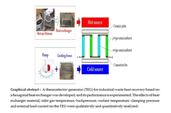
:To study on the thermoelectric power generation for industrial waste heat recovery applied in a hot-air blower, an experimental thermoelectric generator (TEG) bench with the hexagonal heat exchanger and commercially available Bi2Te3 thermoelectric modules (TEMs) was established, and its performance was analyzed. The influences of several important influencing factors such as heat exchanger material, inlet gas temperature, backpressure, coolant temperature, clamping pressure and external load current on the output power and voltage of the TEG were comparatively tested. Experimental results show that the heat exchanger material, inlet gas temperature, clamping pressure and hot gas backpressure significantly affect the temperature distribution of the hexagonal heat exchanger, the brass hexagonal heat exchanger with lower backpressure and coolant temperature using ice water mixture enhance the temperature difference of TEMs and the overall output performance of TEG. Furthermore, compared with the flat-plate heat exchanger, the designed hexagonal heat exchanger has obvious advantages in temperature uniformity and low backpressure. When the maximum inlet gas temperature is 360 °C, the maximum hot side temperature of TEMs is 269.2 °C, the maximum clamping pressure of TEMs is 360 kg/m2, the generated maximum output power of TEG is approximately 11.5 W and the corresponding system efficiency is close to 1.0%. The meaningful results provide a good guide for the system optimization of low backpressure and temperature-uniform TEG, and especially demonstrate the promising potential of using brass hexagonal heat exchanger in the automotive exhaust heat recovery without degrading the original performance of internal combustion engine.
1. Introduction
The continuously updated development of green energy techniques is a good alternative to resolve the global energy crisis and increase environmental protection. Owing to several advantages, such as little vibration, high reliability and durability and no moving parts, thermoelectric modules (TEMs) have been widely developed in photovoltaic, automotive, military, aerospace, wearable devices, wireless sensor networks and microelectronic applications over the past years [1,2,3,4,5,6,7,8,9]. Jaziri et al. [1] described and concluded the exploitation of thermoelectric generators (TEGs) in various fields starting from low-power applications (medical and wearable devices, IoT: internet of things, and WSN: wireless sensor network) to high-power applications (industrial electronics, automotive engines and aerospace). Liu et al. [2] developed a TEG based on concentric filament architecture for low power aerospace microelectronic devices, which was able to produce an electrical voltage of 83.5 mVand an electrical power of 32.1 µW with a planar heat source and temperature of 398.15 K. Willars-Rodríguez et al. [3] created and studied a solar hybrid system including photovoltaic (PV) module, concentrating Fresnel lens, thermo-electric generator (TEG) and running water heat extracting unit. Demir et al. [4] proposed a novel system for recovering waste heat of the automobile by a system based thermoelectric generator, and presented the variations of material properties, efficiency and generated power with respect to temperature and position. Meng et al. [5] proposed a technical solution recycling exhaust gas sensible heat based on thermoelectric power generation, which can produce about 1.47 kW electrical energy per square meter and achieve a conversion efficiency of 4.5% for exhaust gas at 350 degrees. Proto et al. [6] analyzed the results of measurements on thermal energy harvesting through a wearable thermoelectric generator (TEG) placed on the arms and legs whose generated power values were in the range from 5 to 50 μW. Kim et al. [7] demonstrated a self-powered wireless sensor node (WSN) driven by a flexible thermoelectric generator (f-TEG) with a significantly improved degree of practicality, and developed a large-area f-TEG that can be wrapped around heat pipes with various diameters, improving their usability and scalability. Leonov et al. [8] studied a thermoelectric energy harvesting on people that generated power in a range of 5–0.5 mW at ambient temperatures of 15 °C–27 °C, respectively. Holgate et al. [9] conceptualized and modeled a newly designed enhanced multi-mission radioisotope thermoelectric generator (MMRTG) that utilized the more efficient skutterudite-based thermoelectric materials, and presented a discussion of the motivations, modeling results and key design factors. With the rapid development of the economy and society, there is considerable unused waste heat dissipated in industrial heat-generating processes such as power industrial boilers, steelmaking, central air-conditioning, heating equipment and so on.
Thermoelectric generator (TEG) is a promising energy source that includes a hot source (heat exchanger) and a cold source (cooling unit); it can convert the heat into electricity based on the temperature difference of the installed TEMs that are sandwiched between the heat exchanger and cooling unit. In the case of TEG for waste heat recovery, many studies have focused on the application and optimization of the flat-plate heat exchanger to obtain higher power output or evaluate its performance [10,11,12,13,14]. For instance, regarding automotive applications, Zhang et al. [10] developed an automotive exhaust thermoelectric generator (AETEG) with 300 TEGs and water cooling for recovering diesel engine exhaust heat, and obtained 1002.6 W power and 2.1% efficiency when the average exhaust temperature was 823 K and the mass flow rate was 480 g/s. Szybist et al. [11] conducted an experiment to investigate 72 TEGs installed on the downstream of three-way catalytic converter and cooled by engine coolant based on a medium-sized gasoline passenger sedan, and 50 W generation power could be generated in the three typical cycles such as FTP (Federal Test Protocol), HWFET (Highway Fuel Economy Test) and US06 cycles. Kim et al. [12] put forward a novel AETEG with heat pipes and measured a maximum power of 350W with 443 K at the evaporator surface of heat pipes. Merkisz et al. [13] placed 24 TEGs at a distance of about 1.5 m from the end of three-way catalytic converter for a gasoline engine and generated the maximum power (189.3W) and maximum efficiency (1.3%) of AETEG, corresponding to the engine speed of 2600 rpm and 2200 rpm, respectively. Fernandez-Yanez et al. [14,15] developed a diesel engine and a gasoline engine AETEGs with engine coolant cooling, and concluded that the maximum produced power was approximately 270 W for both engines if a bypass was not included. However, two non-negligible problems existing in the flat-plate heat exchanger are the heat uniformity and the unwanted backpressure. The former plays an important role in the average temperature difference and thermoelectric efficiency of TEGs, as it dominates the energy conversion efficiency of heat to electricity. The latter reduces the efficiency of the engine for it seriously affects the original fuel economy and emission performance, or even worse, the lost performance of the engine cannot be compensated by the small generated power of TEG. Therefore, an ideal heat exchanger used in a TEG especially in an AETEG, should provide sufficient surface area to install TEMs as much as possible, increase its surface temperature uniformity, make the backpressure as low as possible and ensure the waste heat gas flow at a high value.
In this paper, we expanded the previous study to develop a low-cost and symmetrical TEG based on a brass hexagonal heat exchanger and the commercially available Bi2Te3 TEMs to recover the waste heat from a hot-air blower, which can simulate the internal combustion engine used in the AETEG. This study aimed to validate the promising potential and advantages of using the hexagonal heat exchanger in waste heat recovery, and analyze the influences of several important influencing factors on the output performance of the TEG. This work can provide an application guideline for industrial heat-generating processes and automotive exhaust heat recovery.
2. Experimental Setup of a TEG System
A detailed schematic diagram of the designed TEG system is shown in Figure 1; it consists of a hot-air blower, a hexagonal heat exchanger, a pump, a radiator, a water tank, a pressure regulator, temperature and pressure sensors (P1 denotes pressure sensor, T1 denotes inlet temperature sensor, T2 denotes outlet temperature sensor) and six groups of TEMs and cooling units. The hot-air blower provides waste heat to the hexagonal heat exchanger, which can also simulate different driving cycles of vehicles by adjusting the gas temperature, flow and pressure. When the hot-air blower works, exhaust gas flows into the hexagonal heat exchanger to provide the hot side temperature, and the cooling water (i.e., coolant) stored in the water tank is circulated with the pump among the cooling units to form the cold side. Therefore, electricity is generated due to the temperature difference between the hot side and cold side of each TEM. To obtain higher temperature difference and better performance, the rotate speed of radiator can be controlled to precool the inlet coolant in cooling units.
The specific architecture of TEG and the dimensions of the hexagonal heat exchanger are shown in Figure 2. Each group of TEMs is sandwiched between the surface of the hexagonal heat exchanger and a cooling unit, and they are clamped with an adjustable force using five bolt and screw combinations. In total, there are 30 TEMs of Bi2Te3-based materials arranged on the six surfaces of the heat exchanger in five columns (i.e., five TEMs in each column are fixed with a common cooling box), and all the TEMs stalled above the surface of the hexagonal heat exchanger are electrically connected in series. Furthermore, to guarantee uniform cold side temperature of TEMs, all the cooling boxes are thermally connected in parallel (i.e., all the inlets of six cooling boxes are connected with the outlet of radiator, all the outlets of six cooling boxes are connected with the inlet of water tank). To evaluate the hot side temperatures distribution of the 30 TEMs, the corresponding K-type thermocouples below each TEM are pasted above each surface of the hexagonal heat exchanger. For the TEG, the Bi2Te3 TEMs (Model Name: TEHP1-1264-0.8) are manufactured by Thermonamic Electronics (Jiangxi, China) Corp. Ltd., whose high conductivity graphite paper is used as the thermally conductive interface material. The specific parameters of the principal components of the TEG system are provided in Table 1.
The real experimental setup of a TEG system is shown in Figure 3; the output of TEG is connected with an adjustable electronic load, and the experiments described in the next section were carried out to evaluate several important influencing factors such as heat exchanger material, inlet gas temperature, backpressure, coolant temperature and external load current on its temperature distribution and output performance.
3. Experimental Results and Discussions
3.1. Temperature Distribution
To analyze the temperature uniformity of the hexagonal heat exchanger, 30 independent K-type thermocouples pasted above its six surfaces are divided into five columns, and each K-type thermocouple is installed right below the central hot side of the corresponding single TEM. The specific surface temperature distribution of the 30 temperature detected locations corresponding to the 30 TEMs is shown in Figure 4. On this occasion, the hexagonal heat exchanger is made of stainless steel (Model Name: 304), its inlet temperature is 260 °C, the pressure regulator is fully open and the effective transfer size of its interior fins is 260 mm in length and 42 mm in width (1.5 mm in thickness). For the interior cavity of heat exchange is much larger than the inlet tube, the gas flows quickly across the inlet section. Furthermore, the gas flow decreases accordingly from column 1 to column 5 because of the pressure caused by the interior fins, which enhances the heat transfer between the hot gas and heat exchanger. Thus, it can be concluded that the section closer to the inlet has the lowest surface temperature, the temperatures of the detected locations marked with blue near the exhaust gas outlet is higher than those in the central area and closer to the exhaust gas inlet because of the gas eddy caused by the sudden narrow outlet tube and the temperatures of the six detected locations in the same column are almost the same (the maximum temperature is below 2 °C). Thus, compared with our previously designed chaos-shaped flat-plate heat exchanger [16,17], the temperature uniformity of the hexagonal heat exchanger is better, which is in good agreement with our expected results.
3.2. Influence of Heat Exchanger Material
For the above designed hexagonal heat exchanger shown in Figure 2, two kinds of different metal materials are adopted without changing its dimension to analyze their influences on the surface temperature distribution and the output performance of TEG system. The first one is made of the above stainless steel (Model Name: 304), and the other one is made of brass. The compared characteristic of TEG with the two different kinds of hexagonal heat exchangers is shown in Figure 5. In this case, the clamping pressure of TEMs above each surface increases is 120 kg/m2, the inlet gas pressure is 70 Pa, the coolant is pumped without radiator, the coolant flow is 5000 L/h and its original temperature is equal to the ambient temperature (27 °C).
Figure 5a,b demonstrate the surface temperature distribution of the two heat exchangers with different inlet temperatures of 155 °C, 200 °C, 260 °C, 315 °C and 360 °C, respectively. Considering the above uniform temperature distribution in each column shown in Figure 4, only the temperature detected locations in the NO.1 surface are selected as the average temperatures of the hexagonal heat exchangers (i.e., the hot side temperatures of TEMs) in each column. It is obvious that the average temperatures of both the stainless steel and brass hexagonal heat exchangers are in direct proportion to the inlet gas temperature. According to the Fourier equation, the absorbed heat (denoted Q) of heat exchanger can be calculated as follows:
where K is the heat conductivity coefficient, A is the heat transfer area, ΔT is the temperature variation and d is the heat transfer distance. For the average heat conductivity of stainless steel 304 is about 16.2 W/m.K, while the one of brass is about 120 W/m.K, which is almost seven times of the former. The detected locations temperatures in the same column validated that the brass hexagonal heat exchanger is much better than the stainless steel hexagonal heat exchanger in heat transfer with the same inlet gas temperature. Properly speaking, when the maximum inlet gas temperature is 360 °C, the maximum temperature of the stainless steel hexagonal heat exchanger (in column 5) is 222.1 °C, while the one of the brass hexagonal heat exchanger (in column 5) is 269.2 °C, which is an increase of 21.2%. According to Equation (1), it can be calculated that the absorbed heat of brass heat exchanger is increased by about 930% because of its higher heat conductivity coefficient.
Figure 5c shows the corresponding open-circuit voltage of TEG with the above two kinds of hexagonal heat exchangers, the open-circuit voltage of TEG based on the two different hexagonal heat exchangers increases with the augment of its inlet gas temperature. Figure 5d provides the measured characteristics curves of voltage and power versus current of TEG with two different hexagonal heat exchangers when the maximum inlet gas temperature is 360 °C. It can be seen that the open-circuit voltage of TEG with the stainless steel hexagonal heat exchanger is only 19.5 V, while the one with the brass hexagonal heat exchanger is 41.6 V, which is an increase of 113.3%. In addition, the maximum power of TEG with the stainless steel hexagonal heat exchanger is only 1.65 W when the current is 0.15 A, while the one with the brass hexagonal heat exchanger is 7.79 W, which is an increase of nearly four times.
For the above coolant of ambient temperature is adopted, the cold side temperatures of TEMs in the same column of both the two kinds of different hexagonal heat exchangers can be seen similar. Furthermore, as shown in Figure 5b, the TEMs installed in the same column above the brass hexagonal heat exchanger have much higher hot side temperatures with the same inlet gas temperatures, it can be concluded that the temperature difference of TEMs with the brass hexagonal heat exchanger is much larger than that with the stainless steel hexagonal heat exchanger for more hot gas heat is absorbed on the same occasion because of the higher heat transfer coefficient of brass. Thus, the brass hexagonal heat exchanger has overwhelming heat-conducting property advantage over the stainless steel hexagonal heat exchanger despite its high cost, and the TEG system with the brass hexagonal heat exchanger has a better output performance.
3.3. Influence of Backpressure
Considering the advantage of the above brass hexagonal heat exchanger used in TEG, the influence of inlet gas backpressure on TEG based on the brass hexagonal heat exchanger is shown in Figure 6. On this occasion, the clamping pressure of TEMs above each surface increases is 120 kg/m2, the coolant is pumped without radiator, the coolant flow is 5000 L/h and its original temperature is equal to the ambient temperature (27 °C), the inlet gas backpressure is adjusted by the regulator opening. For the detected temperature locations in the 5th column of the brass hexagonal heat exchanger have the highest temperature values, Figure 6a,b show the maximum surface temperatures of the brass hexagonal heat exchanger and the open-circuit voltage of TEG corresponding to different inlet gas temperatures with different inlet gas backpressures of 70 Pa, 180 Pa and 220 Pa, respectively. Figure 6c,d show the voltage and output power versus current characteristics with the above different inlet gas backpressures when the maximum inlet gas temperature is 360 °C.
Larger inlet gas backpressure means lower maximum surface temperature and open-circuit voltage with the same inlet gas temperature; the reason of this is that large inlet gas backpressure will decrease the rotation speed of hot-air blower’s fan and the corresponding flow of hot gas. In this case, the heat transfer between hot gas and heat exchanger is reduced, which leads to a lower temperature difference of TEMs based on the same cooling condition. When the maximum inlet gas temperature is 360 °C, the maximum surface temperature of the brass hexagonal heat exchanger is 268.2 °C (70 Pa), 250.1 °C (180 Pa) and 241.3 °C (220 Pa); the open-circuit of TEG is 41.6 V (70 Pa), 35.1 V (180 Pa) and 29.9 V (220 Pa). Furthermore, the open-circuit voltage and output power of TEG are in inverse proportion to the inlet gas backpressures, decreased both output voltage and power with the same output current are accompanied with the augment of inlet gas backpressures. Since the cold side temperature of TEMs in each column with different inlet gas backpressures can be regarded as the same because of the ambient temperature coolant, it can be concluded that the lower inlet gas backpressure is, the larger inlet gas flow will be. Lower inlet gas backpressure contributes to higher temperature differences and better output performance of TEMs, since it ensures higher rotating speed of hot-air blower, and efficient heat conduction between the gas and brass hexagonal heat exchanger on the same occasion.
3.4. Influence of Coolant Temperatures
To ensure lower cold side temperatures and higher temperature differences of TEMs with the same hot side temperatures, three different kinds of coolant were used in the test as follows: case 1: pumped coolant of ambient temperature without radiator; case 2: pumped coolant of ambient temperature with radiator of 100% speed; case 3: pumped coolant of ice water mixture (0 °C) without radiator. Figure 7 shows the characteristic performance of TEG based on the brass hexagonal heat exchanger in the above three cases when the clamping pressure of TEMs above each surface increases is 120 kg/m2, the coolant flow is 5000 L/h, the ambient temperature is 27 °C and the inlet gas backpressure is maintained at 70 Pa.
For Figure 7a, the inlet gas temperatures are changed every five minutes to ensure the steady heat conduction among TEMs, heat exchanger and cooling boxes. The coolant temperatures rise as the inlet gas temperatures increase, the coolant temperature in case 1 is the highest, the coolant temperature in case 2 takes second place, while the coolant temperature in case 3 is the lowest. When the maximum inlet gas temperature is 360 °C, the maximum coolant temperature in case 1 is 45.9 °C, the one in case 2 is 36.6 °C and the one in case 3 is 20.2 °C. Figure 7b shows the open-circuit voltage of TEG with different inlet gas temperatures based on the above three different kinds of coolant. It is obvious that the open-circuit voltage of TEG in case 3 is the largest, the one in in case 2 takes second place, while the one in case 1 is the lowest with the same inlet gas temperature. Figure 7c,d show the performance characteristics of TEG in the above three cases with different load currents when the maximum inlet gas temperature is 360 °C. It can be seen that both the output voltage and power of TEG corresponding to the same load current increase evidently with lower coolant temperatures, the maximum power of TEG in case 1, 2 and 3 is 7.79 W, 8.56 W and 9.65 W, respectively. Additionally, the coolant temperature will increase evidently without a radiator because of the large thermal conductivity of TEMs, and the coolant temperature with radiator can be maintained in a relatively stable range. To ensure larger output power and higher output voltage, a coolant of ice water mixture is recommended in the cooling unit of TEG, as it can evidently enlarge the temperature difference of TEM without consuming extra radiator power.
3.5. Influence of Clamping Pressure
Considering the thermal contact resistance caused by the clamping pressure may affect the hot side and cold side temperatures of TEG, the effect of different clamping pressures on the overall performance of TEG is shown in Figure 8. On this occasion, the coolant of ice water mixture (0 °C) is pumped without radiator, the coolant flow is 5000 L/h, the ambient temperature is 27 °C, the inlet gas backpressure is maintained at 70 Pa and the maximum inlet temperature of heat exchanger is 360 °C. The maximum output power of TEG is 9.65 W, 10.32 W and 11.49 W with different clamping pressures of 120 kg/m2, 240 kg/m2 and 360 kg/m2, respectively. The corresponding open-circuit voltage of TEG is 46.2 V, 49.1 V and 53.3 V, respectively.
From the separate characteristic curves shown in Figure 8a, the slope of voltage versus current decreases with the increased clamping pressure, which means that the inner resistance of TEG increased accordingly. Combined with the above presented results, it demonstrates that the thermal contact resistance of TEG can be reduced for the empty air gap is decreased with large clamping pressure. Thus, much more inlet gas heat from the brass heat exchanger can be absorbed by the hot sides of TEMs, and increasing heat from the cold sides of TEMs can be brought off with large clamping pressure. The larger clamping pressure is, the lower thermal insulator is, which contributes to the enhanced output performance becaused of the lower thermal contact resistance. Therefore, to ensure larger output power and high efficiency, AETEG should be clamped as tight as possible within the allowable pressure of each TEM.
3.6. System Efficiency
For the 30 TEMs of Bi2Te3 based materials used in TEG, the output of TEG can be expressed as follows [1,18,19]:
where n is the p-type and the n-type semiconductor galvanic arms number in each TEM and VTEG and RTEG are the open circuit voltage and internal resistance of TEG, respectively. αPNi is the relative Seebeck coefficient (V/K), αPi and αni are the Seebeck coefficients of the p-type and the n-type semiconductor galvanic arms, respectively. THi and TLi are the hot side and cold side temperature (K), respectively. lp, σP and Ap are the leg length (m), electricity resistivity (Ωm) and cross-sectional area (m2) of a p-type semiconductor galvanic arm, respectively, while ln, σn and An are the leg length, electricity resistivity and cross-sectional area of an n-type semiconductor galvanic arm, respectively.
As shown in Figure 5d, Figure 6d, Figure 7d and Figure 8b the output power of the TEG reaches its maximum value (denoted PTEG) when the external load resistance (denoted Rm) is equal to its internal resistance, and is expressed as:
The heat input to the hexagonal heat exchanger is obtained as [20]:
where Gh is the volume flow rate of inlet gas, ρh is the density of inlet gas, Ch is the heat capacity of inlet gas at constant pressure, while Thi and Tho are the inlet gas temperature and outlet gas temperature of hot gas, respectively. In this case, the maximum TEG system efficiency η can be calculated as follows:
Figure 9 shows the temperature drop and outlet temperature of hot gas along the brass hexagonal heat exchanger when the inlet gas temperature changes from 155 °C to 360 °C. On this occasion, the clamping pressure of TEMs above each surface increases to 360 kg/m2, the pumped coolant of ice water mixture (0 °C) without radiator is adopted, the ambient temperature is 27 °C and the inlet gas backpressure is 70 Pa (the corresponding flow rate is 0.18 m3/h). It can be seen that both the temperature drops and outlet temperature increases with increasing inlet gas temperatures; the maximum temperature drop between the inlet and outlet gas is within 50 °C.
Experimental results of both the maximum output power and corresponding system efficiency of TEG are shown in Figure 10 with respect to the inlet gas temperatures. As shown in Figure 10, for fixed inlet gas flow rates and backpressures, the maximum output power and system efficiency of TEG based on the coolant of ice water mixture increase with increasing inlet gas temperature. When the maximum inlet gas temperature is 360 °C, the outlet gas temperature is 315.1 °C, the generated maximum output power of TEG is 11.49 W, and the corresponding system efficiency is 0.96%. For the maximum temperature limitation (360 °C) of hot-air blower outlet, the maximum surface temperature of the brass hexagonal heat exchanger shown in Figure 6 is only 269.2 °C, which is much lower than the operated operation temperature of TEM (330 °C). Thus, if the maximum surface temperature of the brass hexagonal heat exchanger can be raised to 330 °C, it can be deduced that the maximum output power of TEG will approach 20 W, and the corresponding system efficiency will be above 1.5%.
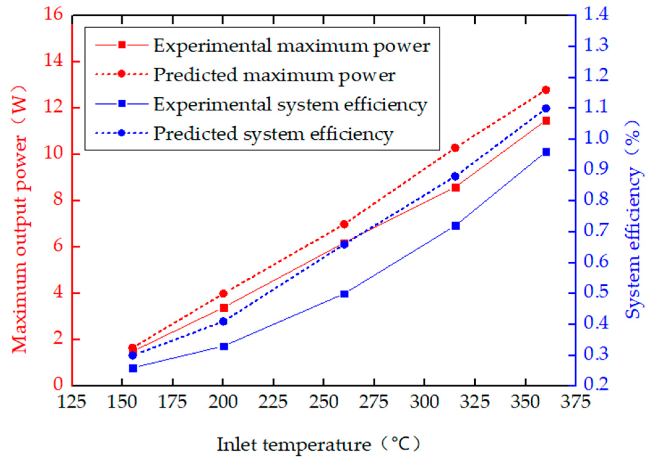
Furthermore, to validate the above numerical model of TEG, Figure 11 shows the comparison between the predicted and measured maximum power and corresponding system efficiency with different matched load resistance, the clamping pressure of TEMs above each surface increases is 360 kg/m2, the pumped coolant of ice water mixture (0 °C) without radiator is adopted, the coolant flow is 5000 L/h, the ambient temperature is 27 °C and the inlet gas backpressure is 70 Pa (the corresponding flow rate is 0.18 m3/h). It can be seen that the above numerical model can predict the performances of TEG when the inlet gas temperature changes from 125 °C to 360 °C. At low temperatures, there is a good agreement between the experimental performances and the predicted results. However, at high temperatures, the discrepancy between the experimental performances and predicted values increases evidently and is also acceptable. The main reason is that the heat losses from the hot sides to cold sides of TEMs are not considered in the numerical model, which plays a more important role in the heat transfer at high temperatures. Overall, to estimate the performance and establish the precise model of TEG, the properties of the thermoelectric materials used in TEMs should be assumed to be variables, the heat losses from the uncovered surface, TEMs gap and hot sides to cold sides should be taken into account.
4. Conclusions
Waste heat recovery based on TEMs presents a promising research focus worldwide, but enhancing the output performance and system efficiency of TEG remains a significant challenge. In this study, a TEG system with the low-temperature and common commercially available Bi2Te3 TEMs and a hexagonal heat exchanger is designed for the waste heat recovery of an industrial hot-air blower. The influences of different operating conditions such as material, backpressure, inlet gas temperature, clamping pressure and coolant temperature on the temperature distribution, open-circuit voltage, the maximum output power and the system efficiency of TEG are reported from the experimental measurements. The experimental results demonstrate that the surface temperature distribution of hexagonal heat exchanger is uniform in each column, and is greatly affected by the adopted material of heat exchanger and the backpressure of inlet gas.
The comparisons indicate that the brass hexagonal heat exchanger has better heat conduction, lower backpressure can enhance the gas flow rate and the average surface temperature of heat exchanger (i.e., hot side temperature of TEMs) and the coolant of ice water mixture contributes to lower cold side temperature of TEMs. Furthermore, the maximum output power and system efficiency of TEG is proportional to the practical temperature differences of TEMs caused by inlet gas temperatures, backpressures, clamping pressures and coolant temperature. The designed brass hexagonal heat exchanger has low pressure drop, and it is very suitable for the automotive exhaust thermoelectric generator. Further experiments are planned to optimize the TEG and apply it in the automotive exhaust heat recovery.
Author Contributions
T.L. and Y.Y. performed the experiments and data analysis. R.Q. designed the experiments and wrote the manuscript. Y.C. and B.T. offered valuable discussions in analyses and revised the manuscript. All authors have read and agreed to the published version of the manuscript.
Funding
This research received no external funding.
Acknowledgments
“This work was supported by the National Natural Science Foundation of China (No. 51977061, 61903129, 51407063)”and “This work was supported by the Doctor Scientific Research Foundation of Hubei University of Technology (No. BSQD13064)”.
Conflicts of Interest
The authors declare no conflict of interest.
List of Notations
| P1 | inlet gas temperature sensor |
| T1 | inlet gas temperature sensor |
| T2 | outlet gas temperature sensor |
| n | p-type and the n-type semiconductor galvanic arms number |
| VTEG | open circuit voltage of TEG |
| RTEG | internal resistance of TEG |
| αPNi | relative Seebeck coefficient |
| αpi | Seebeck coefficients of the p-type semiconductor galvanic arms |
| αni | Seebeck coefficients of the n-type semiconductor galvanic arms |
| THi | hot side temperature of TEM |
| TLi | cold side temperature of TEM |
| lp | leg length of a p-type semiconductor galvanic arm |
| σp | electricity resistivity of a p-type semiconductor galvanic arm |
| Ap | cross-sectional area of a p-type semiconductor galvanic arm |
| ln | leg length of a n-type semiconductor galvanic arm |
| σn | electricity resistivity of a n-type semiconductor galvanic arm |
| An | cross-sectional area of a p-type semiconductor galvanic arm |
| PTEG | maximum output power of TEG |
| Rm | external load resistance |
| Qh | heat input to the cylindrical heat exchanger |
| Gh | volume flow rate of inlet gas |
| ρh | density of inlet gas |
| Ch | heat capacity of inlet gas at constant pressure |
| Thi | inlet gas temperature |
| Tho | outlet gas temperature |
| η | maximum TEG system efficiency |
References
- Jaziri, N.; Boughamoura, A.; Müller, J.; Mezghani, B.; Tounsi, F.; Ismail, M. A comprehensive review of thermoelectric generators: Technologies and common applications. Energy Rep. 2019. [Google Scholar] [CrossRef]
- Liu, K.; Tang, X.; Liu, Y.; Yuan, Z.; Li, J.; Xu, Z.; Zhang, Z.; Chen, W. High performance and integrated design of thermoelectric generator based on concentric filament architecture. J. Power Sources 2018, 393, 161–168. [Google Scholar] [CrossRef]
- Willars-Rodríguez, F.J.; Chávez-Urbiola, E.A.; Vorobiev, P.; Vorobiev, Y.V. Investigation of solar hybrid system with concentrating Fresnel lens, photovoltaic and thermoelectric generators. Int. J. Energy Res. 2017, 41, 377–388. [Google Scholar] [CrossRef]
- Demir, M.E.; Dincer, I. Performance assessment of a thermoelectric generator applied to exhaust waste heat recovery. Appl. Therm. Eng. 2017, 120, 694–707. [Google Scholar] [CrossRef]
- Meng, F.K.; Chen, L.G.; Feng, Y.L.; Xiong, B. Thermoelectric generator for industrial gas phase waste heat recovery. Energy 2017, 135, 83–90. [Google Scholar] [CrossRef]
- Proto, A.; Bibbo, D.; Cerny, M.; Vala, D.; Kasik, V.; Peter, L.; Conforto, S.; Schmid, M.; Penhaker, M. Thermal energy harvesting on the bodily surfaces of arms and legs through a wearable thermo-electric generator. Sensors 2018, 18, 1927. [Google Scholar] [CrossRef] [PubMed] [Green Version]
- Kim, Y.; Gu, H.M.; Kim, C.; Choi, H.; Lee, G.; Kim, S.; Yi, K.; Lee, S.; Cho, B. High-performance self-powered wireless sensor node driven by a flexible thermoelectric generator. Energy 2018, 162, 526–533. [Google Scholar] [CrossRef]
- Leonov, V. Thermoelectric energy harvesting of human body heat for wearable sensors. IEEE Sens. J. 2013, 13, 2284–2291. [Google Scholar] [CrossRef]
- Holgate, T.-C.; Bennett, R.; Hammel, T.; Caillat, T.; Keyser, S.; Sievers, B. Increasing the efficiency of the multi-mission radioisotope thermoelectric generator. J. Electron. Mater. 2015, 44, 1814–1821. [Google Scholar] [CrossRef]
- Zhang, Y.L.; Cleary, M.; Wang, X.W.; Kempf, N.; Schoensee, L.; Yang, J.; Joshi, G.; Meda, L. High-temperature and high-power-density nanostructured thermoelectric generator for automotive waste heat recovery. Energy Convers. Manag. 2015, 105, 946–950. [Google Scholar] [CrossRef] [Green Version]
- Szybist, J.; Davis, S.; Thomas, J.F.; Kaul, B.C. Performance of a Half-Heusler thermoelectric generator for automotive application. SAE Tech. Pap. 2018, 1. [Google Scholar] [CrossRef]
- Kim, S.K.; Won, B.C.; Rhi, S.H.; Kim, S.H.; Yoo, J.H.; Jang, J.C. Thermoelectric power generation system for future hybrid vehicles using hot exhaust gas. J. Electron. Mater. 2011, 40, 778–783. [Google Scholar] [CrossRef]
- Merkisz, J.; Fuc, P.; Lijewski, P.; Ziolkowski, A.; Galant, M.; Siedlecki, M. Analysis of an increase in the efficiency of a spark ignition engine through the application of an automotive thermoelectric generator. J. Electron. Mater. 2016, 45, 4028–4037. [Google Scholar] [CrossRef] [Green Version]
- Fernandez-Yanez, P.; Armas, O.; Capetillo, A.; Martinez-Martinez, S. Thermal analysis of a thermoelectric generator for light-duty diesel engines. Appl. Energy 2018, 226, 690–702. [Google Scholar] [CrossRef]
- Fernandez-Yanez, P.; Armas, O.; Kiwan, R.; Stefanopoulou, A.G.; Boehman, A.L. A thermoelectric generator in exhaust systems of spark-ignition and compression-ignition engines. A comparison with an electric turbo-generator. Appl. Energy 2018, 229, 80–87. [Google Scholar] [CrossRef]
- Quan, R.; Zhou, W.; Yang, G.Y.; Quan, S.H. A hybrid maximum power point tracking method for automobile exhaust thermoelectric generator. J. Electron. Mater. 2017, 46, 2676–2683. [Google Scholar] [CrossRef]
- Quan, R.; Liu, G.Y.; Wang, C.J.; Zhou, W.; Huang, L.; Deng, Y.D. Performance investigation of an exhaust thermoelectric generator for military SUV application. Coatings 2018, 8, 45. [Google Scholar] [CrossRef] [Green Version]
- Fraisse, G.; Ramousse, J.; Sgorlon, D.; Goupil, C. Comparison of different modeling approaches for thermoelectric elements. Energy Convers. Manag. 2013, 65, 351–366. [Google Scholar] [CrossRef]
- Quan, R.; Wang, C.J.; Wu, F.; Chang, Y.F.; Deng, Y.D. Parameter matching and optimization of an isg mild hybrid powertrain based on an automobile exhaust thermoelectric generator. J. Electron. Mater. 2019. [Google Scholar] [CrossRef]
- Niu, X.; Yu, J.L.; Wang, S.Z. Experimental study on low-temperature waste heat thermoelectric generator. J. Power Sources 2009, 188, 621–626. [Google Scholar] [CrossRef]
Figure 1.
Schematic of an experimental setup of a TEG System. TEM: thermoelectric module.
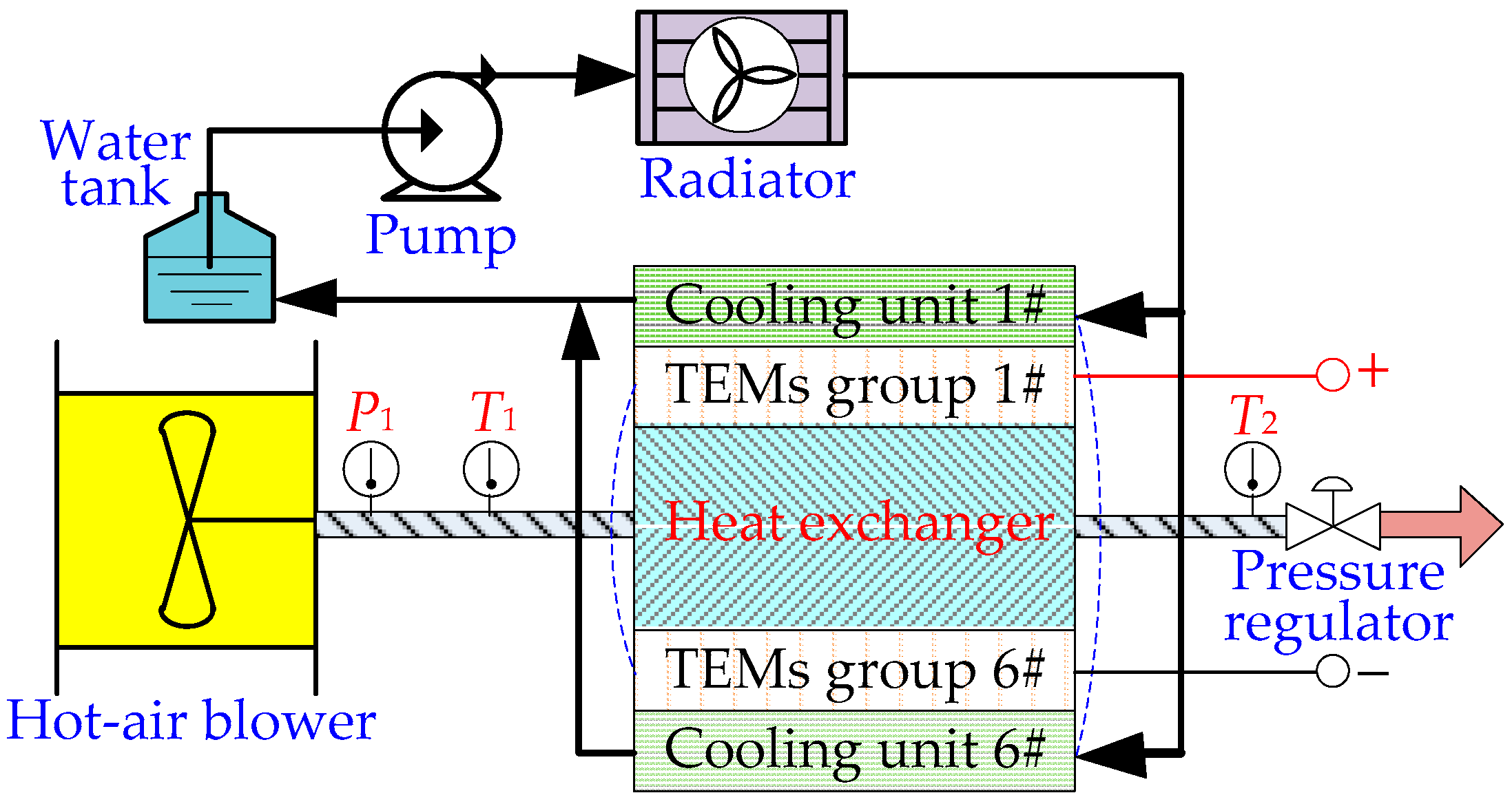
Figure 2.
TEG architecture.

Figure 3.
Real experimental setup of a TEG system.
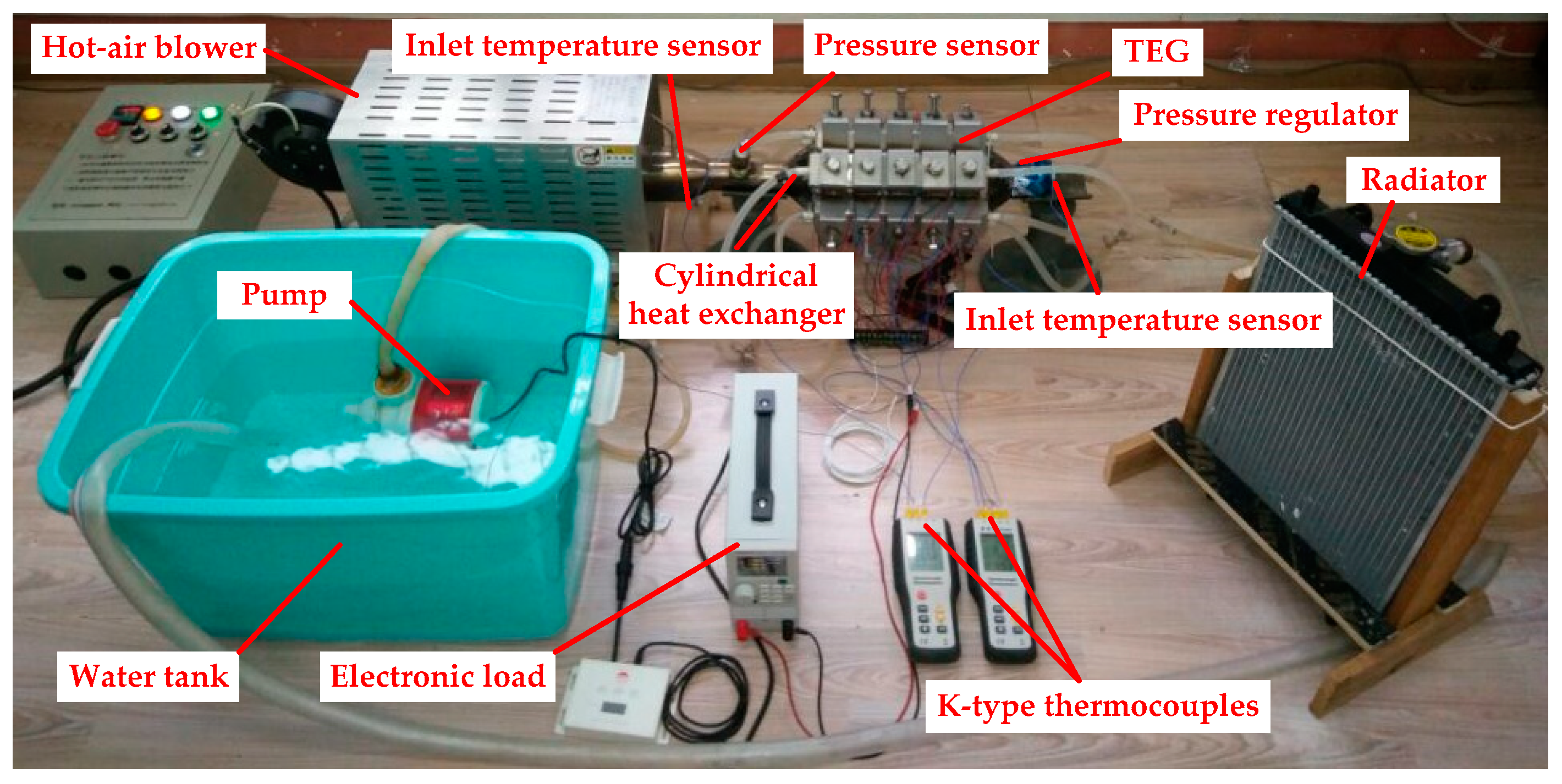
Figure 4.
The surface temperature distribution of the hexagonal heat exchanger.
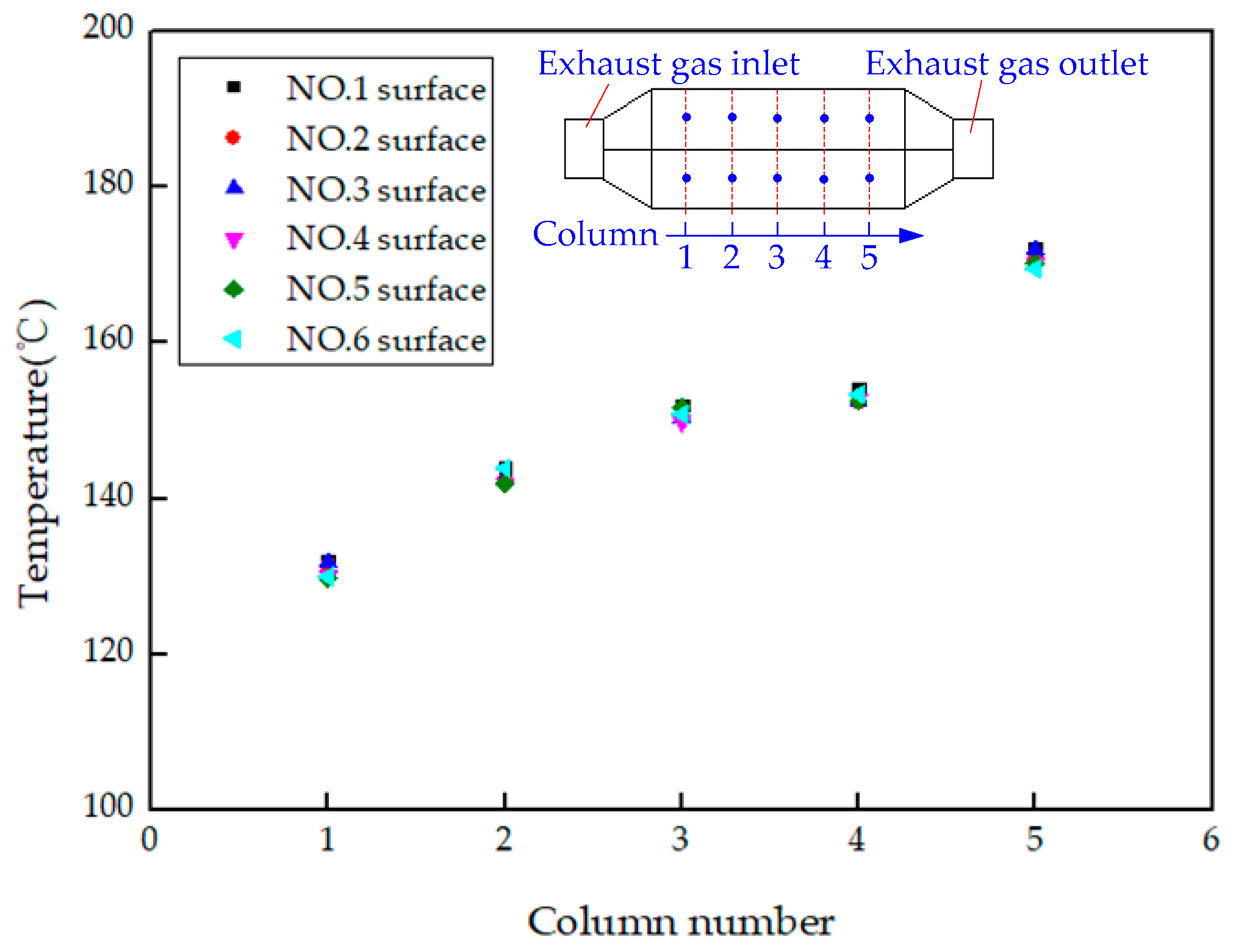
Figure 5.
The compared characteristic performance of TEG with different heat exchanger materials. (a) Surface temperature distribution of the stainless steel heat exchanger. (b) Surface temperature distribution of the brass heat exchanger. (c) Open-circuit voltage of TEG with inlet gas temperatures. (d). Voltage and power versus current when the maximum inlet temperature is 360 °C.
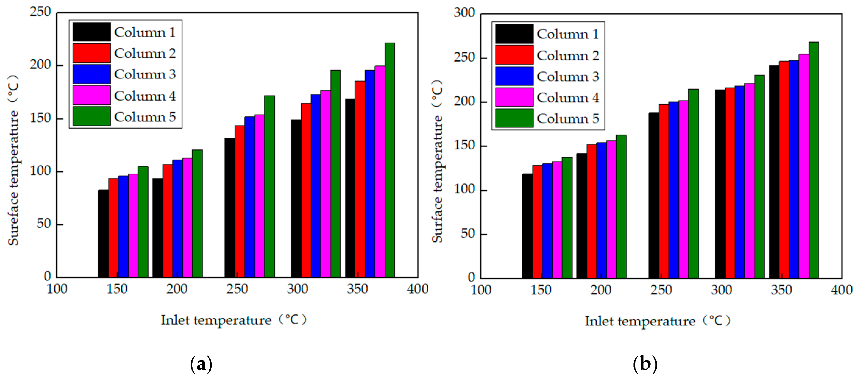
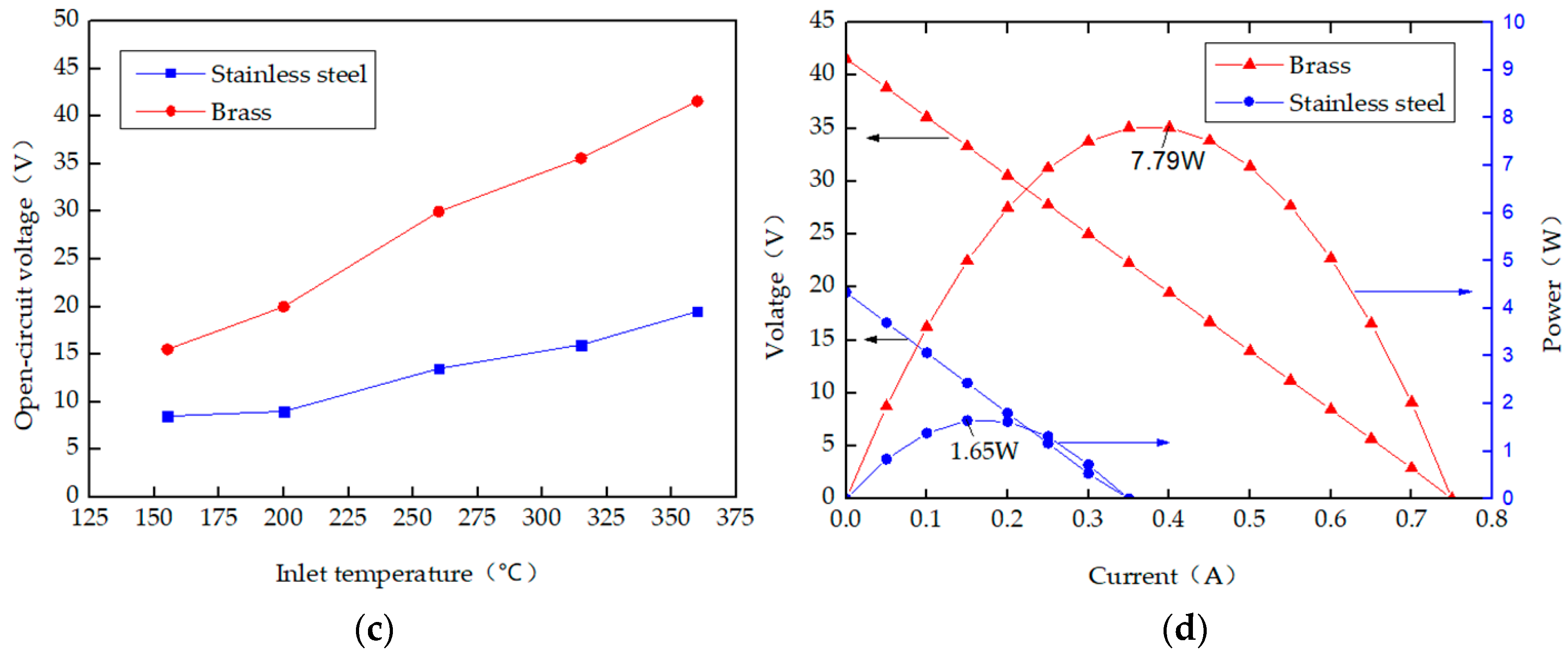
Figure 6.
The compared characteristic performance of TEG based on the brass hexagonal heat exchanger with different inlet gas backpressures. (a) Maximum surface temperatures of the brass heat exchanger with inlet gas temperatures. (b) Open-circuit voltage of TEG with inlet gas temperatures. (c) Voltage versus current when the maximum inlet temperature is 360 °C. (d) Power versus current when the maximum inlet temperature is 360 °C.
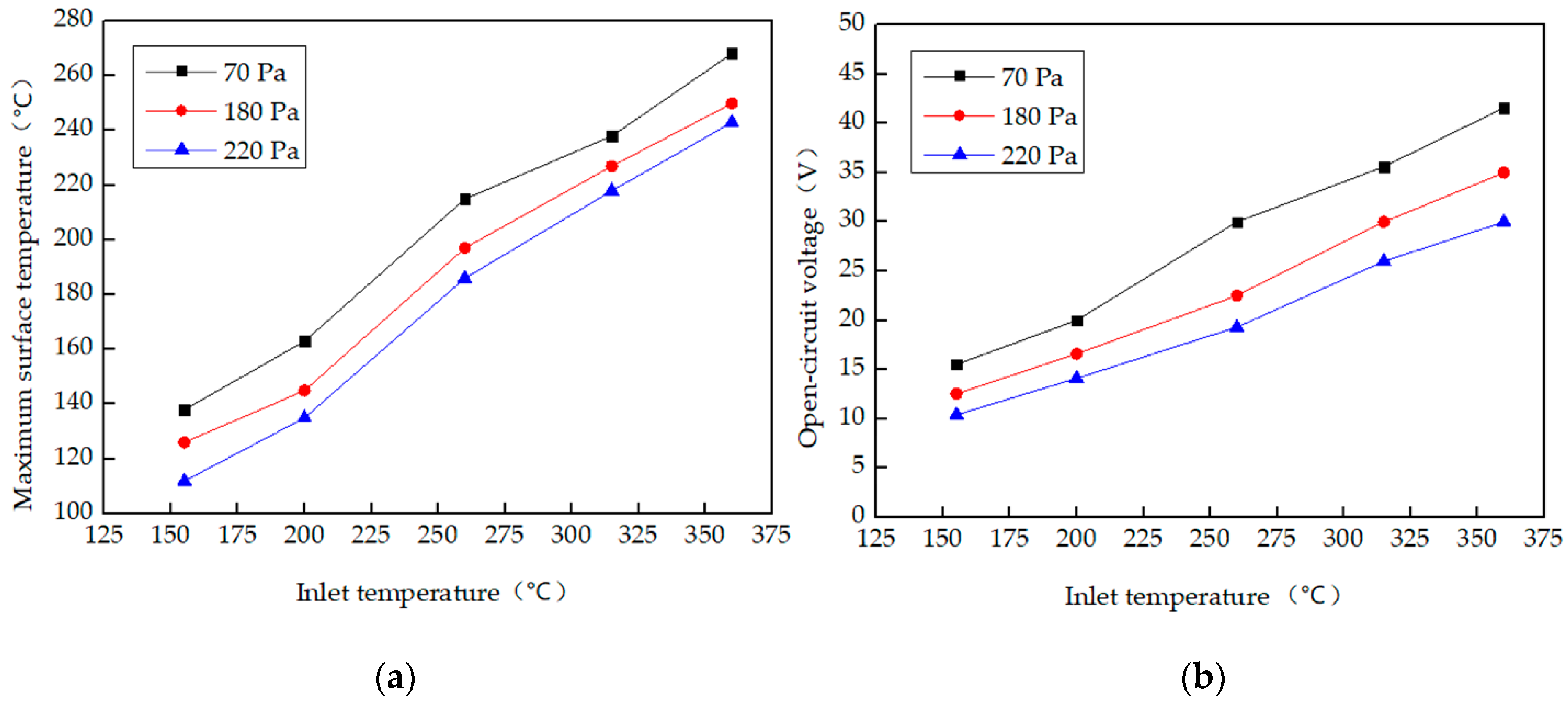

Figure 7.
The compared characteristic performance of TEG based on the brass hexagonal heat exchanger in different coolant cases. (a) Coolant temperatures of TEG with inlet gas temperatures. (b) Open-circuit voltage of TEG with inlet gas temperatures. (c) Voltage versus current when the maximum inlet temperature is 360 °C. (d) Power versus current when the maximum inlet temperature is 360 °C.
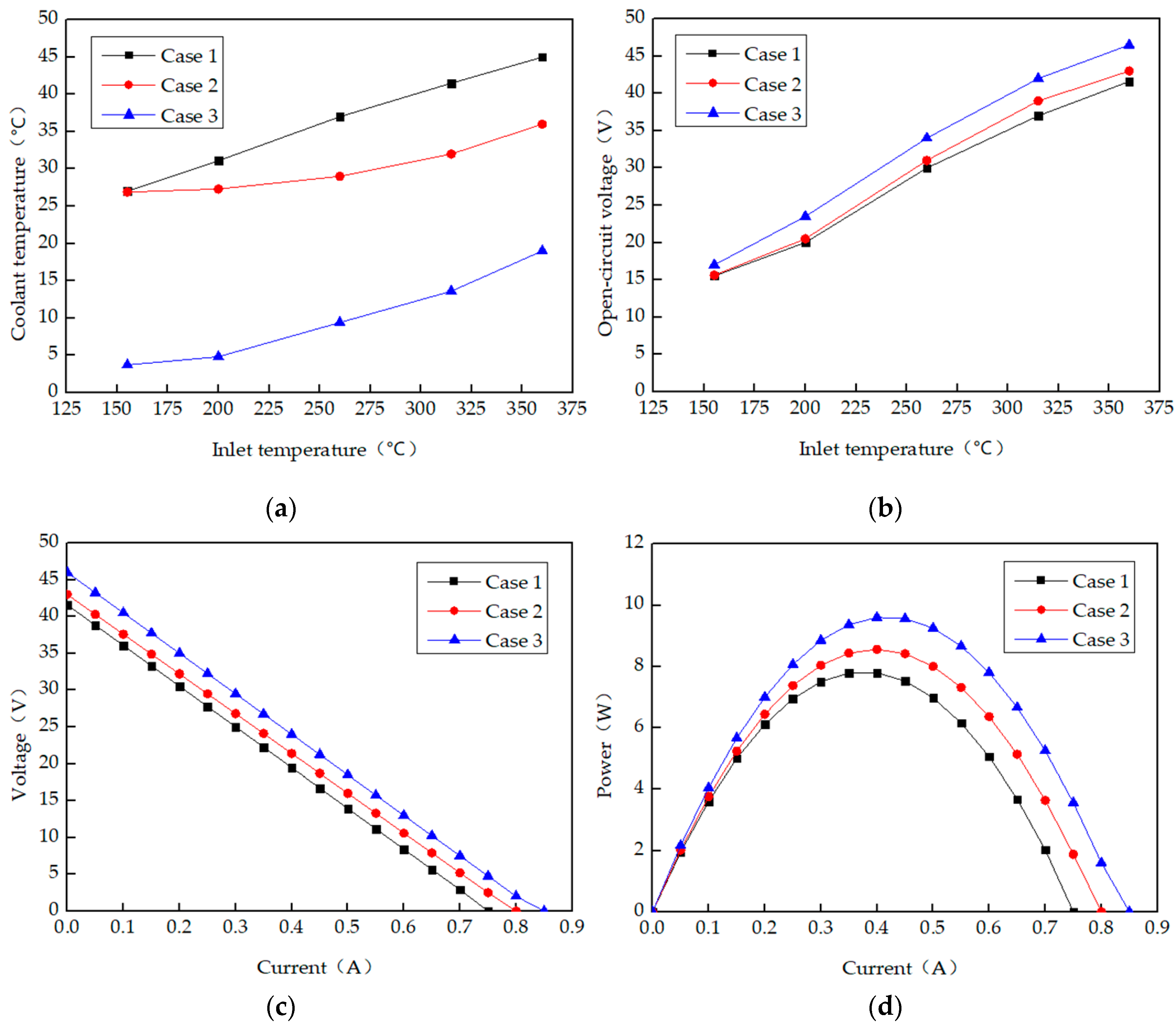
Figure 8.
TEG performance with clamping pressure of 120 kg/m2, 240 kg/m2 and 360 kg/m2. (a) Voltage versus current curves, (b) power versus current curves.
Figure 8.
TEG performance with clamping pressure of 120 kg/m2, 240 kg/m2 and 360 kg/m2. (a) Voltage versus current curves, (b) power versus current curves.

Figure 9.
The decrease in temperature and the outlet gas temperature for different inlet gas temperatures.
Figure 9.
The decrease in temperature and the outlet gas temperature for different inlet gas temperatures.

Figure 10.
The overall output performance of TEG with respect to the inlet gas temperature. (a) Maximum output power; (b) system efficiency.
Figure 10.
The overall output performance of TEG with respect to the inlet gas temperature. (a) Maximum output power; (b) system efficiency.
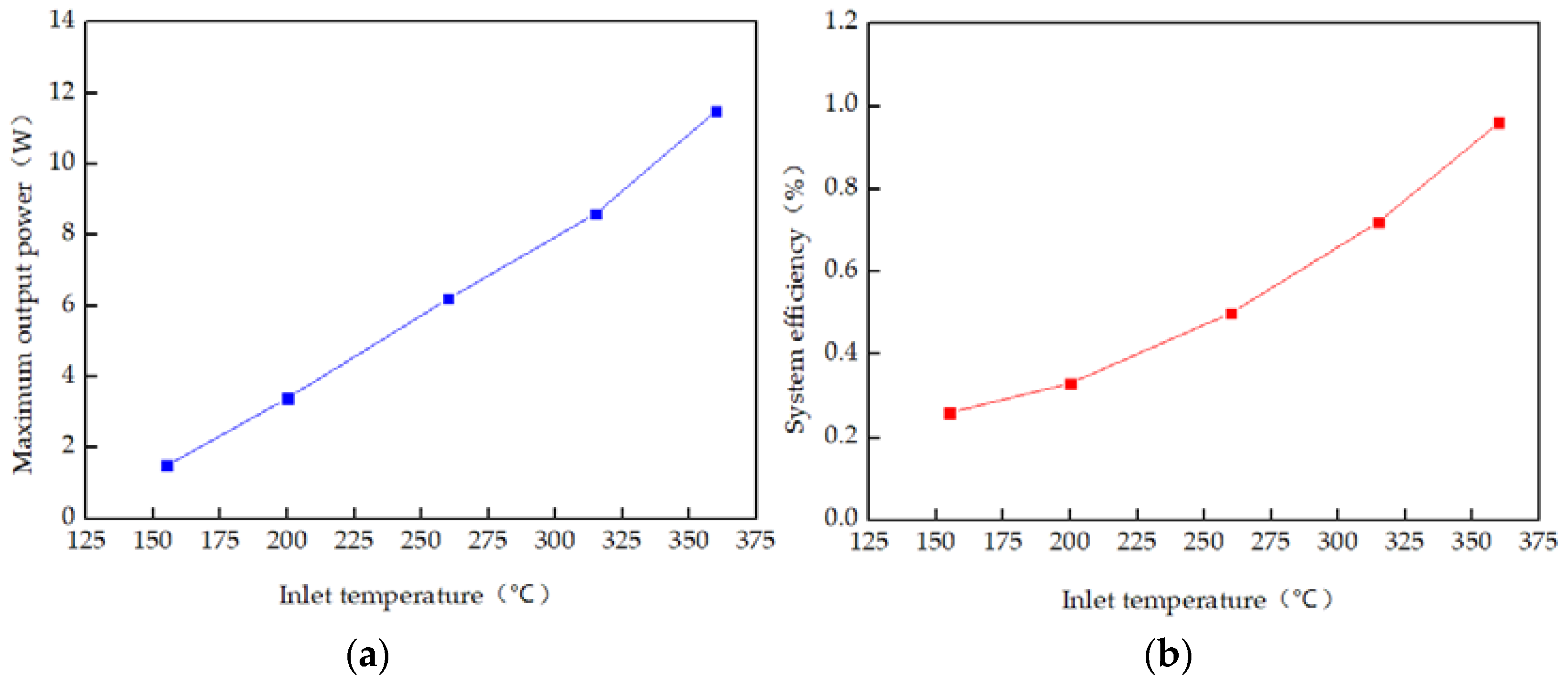
Figure 11.
Comparison between the predicted and measured maximum power and corresponding system efficiency of TEG.
Figure 11.
Comparison between the predicted and measured maximum power and corresponding system efficiency of TEG.

Table 1.
Parameters of the principal components of a TEG system.
| Parameters | Value |
|---|---|
| Dimension of TEM | 40 mm × 40 mm × 40 mm |
| Maximum operation temperature of TEM | 400 °C |
| Rated operation temperature of TEM | 330 °C |
| Maximum conversion efficiency of TEM | 6.5% |
| Dimension of cooling box | 250 mm × 50 mm × 20 mm |
| Material of cooling box | Aluminum |
| Thickness of cooling box | 1 mm |
| Thickness of heat exchanger | 2 mm |
| Maximum power of pump | 40 W |
| Maximum flow of pump | 5000 L/H |
| Rated power of radiator | 100 W (24V DC) |
| Rated power of hot-air blower | 2000 W |
© 2020 by the authors. Licensee MDPI, Basel, Switzerland. This article is an open access article distributed under the terms and conditions of the Creative Commons Attribution (CC BY) license (http://creativecommons.org/licenses/by/4.0/).
Share and Cite
MDPI and ACS Style
Quan, R.; Li, T.; Yue, Y.; Chang, Y.; Tan, B. Experimental Study on a Thermoelectric Generator for Industrial Waste Heat Recovery Based on a Hexagonal Heat Exchanger. Energies 2020, 13, 3137. https://doi.org/10.3390/en13123137
AMA Style
Quan R, Li T, Yue Y, Chang Y, Tan B. Experimental Study on a Thermoelectric Generator for Industrial Waste Heat Recovery Based on a Hexagonal Heat Exchanger. Energies. 2020; 13(12):3137. https://doi.org/10.3390/en13123137
Chicago/Turabian StyleQuan, Rui, Tao Li, Yousheng Yue, Yufang Chang, and Baohua Tan. 2020. "Experimental Study on a Thermoelectric Generator for Industrial Waste Heat Recovery Based on a Hexagonal Heat Exchanger" Energies 13, no. 12: 3137. https://doi.org/10.3390/en13123137
Note that from the first issue of 2016, this journal uses article numbers instead of page numbers. See further details here.