Article

A Block Bi-Diagonalization-Based Pre-Coding for Indoor Multiple-Input-Multiple-Output-Visible Light Communication System

by
Prabu Subramani
1,
Ganesh Babu Rajendran
2,
Jewel Sengupta
3,
Rocío Pérez de Prado
4,* and
Parameshachari Bidare Divakarachari
5
1
Department of Electronics and Communication Engineering, Mahendra Institute of Technology, Mahendhirapuri, Mallasamudram West, Tiruchengode, Tamil Nadu 637503, India
2
Department of Electronics and Communication Engineering, SRM TRP Engineering College, Mannachanallur, Taluk, Irungalur, Tamil Nadu 621105, India
3
Department of Computer Science, Visvesvaraya Technological University, Machhe, Belgaum, Karnataka 590018, India
4
Telecommunication Engineering Department, University of Jaén, 23071 Jaén, Spain
5
Department of Telecommunication Engineering, GSSS Institute of Engineering and Technology for Women, Mysuru, Karnataka 570016, India
*
Author to whom correspondence should be addressed.
Energies 2020, 13(13), 3466; https://doi.org/10.3390/en13133466
Submission received: 6 May 2020 / Revised: 3 June 2020 / Accepted: 30 June 2020 / Published: 4 July 2020
(This article belongs to the Section F: Electrical Engineering)

Abstract

:
Visible Light Communication (VLC) is a promising field in optical wireless communications, which uses the illumination infrastructure for data transmission. The important features of VLC are electromagnetic interference-free, license-free, etc. Additionally, Multiple-Input-Multiple-Output (MIMO) techniques are enabled in the VLC for enhancing the limited modulation bandwidth by its spectral efficiency. The data transmission through the MIMO-VLC system is corrupted by different interferences, namely thermal noise, shot noise and phase noise, which are caused by the traditional fluorescent light. In this paper, an effective precoding technique, namely Block Bi-Diagonalization (BBD), is enabled to mitigate the interference occurring in the indoor MIMO-VLC communications. Besides, a Quadrature Amplitude Modulation (QAM) is used to modulate the signal before transmission. Here, the indoor MIMO-VLC system is developed to analyze the communication performance under noise constraints. The performance of the proposed system is analyzed in terms of Bit Error Rate (BER) and throughput. Furthermore, the performances are compared with three different existing methods such as OAP, FBM and NRZ-OOK-LOS. The BER value of the proposed system of scenario 1 is 0.0501 at 10 dB, which is less than that of the FBM technique.

Graphical Abstract

1. Introduction

Visible Light Communication (VLC) is developing as a promising technique for delivering global wireless connection. This VLC is used in 5th generation and beyond wireless communication systems, specifically in indoor applications. VLC communication is secure and it is considered as a green alternative to the conventional Radio Frequency Communications (RFC) [1,2]. RF-based communication causes spectrum shortage with the increasing demand for higher data rate, but the VLC has an unregulated and license-free spectrum which helps to satisfy higher data rate [3]. In VLC, the Intensity Modulation with Direct Detection (IM/DD) is used to maintain the transmitted signal as positive and real [4]. The characteristics of VLC are IM/DD, large bandwidth and unlicensed spectrum, etc [5]. Moreover, the main feature of the VLC that is unique from remaining optical wireless communication systems, e.g., infrared communication is that it has the capacity to deliver the illumination and communication at the same time [6]. The VLC technology uses the Light Emitting Diodes (LEDs) in transmitters due to the characteristics of low cost, illumination and higher bandwidth as well as the photodetectors (PDs) used in receivers [7].
The additional characteristics of LEDs are higher lifetime, mercury-free, low power consumption and high brightness [8,9]. However, the VLC system faces many challenges such as LED non-linearity, shadowing and blocking, limited mobility and Inter-Symbol Interference (ISI) due to multipath [10]. In order to overcome the aforementioned problems, the Multiple-Input-Multiple-Output (MIMO) and Orthogonal Frequency Division Multiplexing (OFDM) are utilized for enhancing the ability of the VLC systems [11,12]. The incorporation of MIMO improves the performances of VLC, especially in high range data transmission [13]. The problems faced by the MIMO VLC system are given as follows: Generally, the MIMO VLC channel exists in static Line Of Sight (LOS) conditions. The correlations due to the static LOS are associated to the LED array parameters and PDs array. The transmission performance is highly affected due to the strong correlation in the channel matrix [14]. An effective precoding technique is to be developed for avoiding the interference and achieve user fairness [15]. The major contributions of this research paper are stated as follows:
  • In this paper, a 4 × 4 indoor MIMO-VLC system is developed to improve the data rate and reliability in data transmission. Here, 4 × 4 is defined as the installation of 4 LEDs in the transmitter side and 4 PDs in the receiver side.
  • Block Bi-Diagonalization (BBD)-based precoding is presented in this communication system to remove the inferences caused due to the thermal noise, shot noise and phase noise. This is because these noise constraints affect the signal, which is transmitted through the MIMO-VLC system. Additionally, the BBD-based precoding used in this VLC system has less computation complexity.
  • Quadrature Amplitude Modulation (QAM)-based modulation also improves the transmission of the MIMO-VLC transmitter. The Bit Error Rate (BER) and throughput of the proposed system are analyzed for three different scenarios under noise constraints.
The organization of this research paper is given as follows: the literature survey about the recent research related to the indoor MIMO-VLC system are presented in Section 2. The system model of the indoor MIMO-VLC system, channel model and BBD-based precoding are described in Section 3. The experimental results and comparative analysis of the proposed system are depicted in Section 4. Finally, the conclusion is made in Section 5.

2. Literature Survey

Current research related to the indoor MIMO-VLC systems is presented in this section along with its advantages and limitations. The existing studies are given as follows:
Hsu, C.W., Chow, C.W., Lu, I.C., Liu, Y.L., Yeh, C.H. and Liu, Y. [16] presented the 3 × 3 MIMO-VLC system for enhancing the data rate. The pre-equalizer circuit is utilized to improve the LED transmitter bandwidth over VLC communications. Here, the channel matrix computation is simplified by a MIMO training sequence that depends on the time-multiplexing. The SNR decides the order of the modulation through the data transfer of VLC communications. Moreover, the spectral efficiency is improved by using OFDM. The phosphor LED utilized in the VLC communications has the narrow modulation bandwidth that creates the issues in high speed communication.
Wang, R., Gao, Q., You, J., Liu, E., Wang, P., Xu, Z. and Hua, Y. [17] developed the design of a linear transceiver for an indoor VLC with various LEDs. There are two different VLC systems that are analyzed, such as VLC with white LED and VLC with Red/Green/Blue (RGB) LEDs. The Additive White Gaussian Noise (AWGN) is considered as the noise model in this MIMO-VLC system. The lighting constraints are considered to jointly optimize the transmitter precoding and the offset. The lighting constraints are color illumination, optical power and non-negativeness. The MSE is reduced and transmission reliability is improved by formulating the non-convex transceiver design problems. Here, the communication performances are evaluated only under AWGN noise; it doesn’t consider the shot and thermal noise for VLC communications.
Park, K.H., Oubei, H.M., Alheadary, W.G., Ooi, B.S. and Alouini, M.S. [18] presented the design of the Mirror Diversity Receiver (MDR) in a 2 × 2 MIMO-VLC system. The modulation and demodulation considered in this 2 × 2 MIMO-VLC system is the ID-MM scheme. This MDR design minimizes the channel correlation by stopping the incoming light from one direction and enhancing the channel gain from the light obtained from the other direction. Besides, the channel gain is enhanced by positioning a double-sided mirror among the PD of the receiver. The channel gains of the MDR are analyzed in various locations of the receiver. Additionally, the channel capacity is improved by formulating the optimization problem based on the height of the mirrors. If PD receives more light from the LED, this results in intensity loss in the communication.
Kim, B.W. and Jung, S.Y. [19] analyzed the communication of the Distributed MIMO (D-MIMO)-relaying VLC scheme. This D-MIMO-relaying VLC scheme relays the optical signals from the MIMO VLC system to the secluded indoor area. Here, the AWGN is assumed as background noise to evaluate VLC communications. The channel capacity’s tight upper bound is derived by utilizing the multiple access relay channels and sum rate. This work selects the optimum relay parameters such as distance among relays, amount of LED–PD pairs in a relay and height of relays. The selection of optimum relay parameters helps to achieve improved channel capacity through the MIMO-VLC communication. It fails to analyse the error rate during the data transmission.
Akande, K.O. and Popoola, W.O [20] presented the MIMO in a VLC system for enhancing the BER and spectral efficiency of carrierless amplitude and phase modulation (CAP). The signals of CAP are generated by mapping the information bits into Quadrature Amplitude Modulation (QAM). The noise model considered in this MIMO CAP system is AWGN with double-sided power spectral density and zero mean. Moreover, each LED’s emitted intensity is scaled with weighting factor to develop an effective precoding technique, namely the Power Factor Imbalance (PFI). The PFI-based precoding enhances the power efficiency and infuses the dissimilarity. The implementation of PFI neither maximizes the total transmit power, nor increases the decoder complexity in the design of the MIMO-VLC system.
Hong, Y., Wu, T. and Chen, L.K. [21] developed the MIMO-OFDM-VLC system along with a receiver module with angular diversity for improving the BER. The Channel State Information (CSI) evaluated for this VLC system are multiple reflections, LED nonlinearity and modulation bandwidth.The channel of MIMO-VLC is decomposed into independent parallel sub-channels by utilizing the Singular Value Decomposition (SVD). Subsequently, the bit and power loading is utilized for sub channels to enhance the system capacity. An improvement in channel diversity is obtained by using the receiver module with four receiver heads, which are oriented to the optimized polar angle with various azimuthal angles. The system performance is limited when the polar angle is too large.
Marshoud, H., Sofotasios, P.C., Muhaidat, S., Sharif, B.S. and Karagiannidis, G.K. [22] presented an Optical Adaptive Precoding (OAP) scheme for the MIMO-VLC downlink systems. The signal-to-interference-plus-noise ratio (SINR) is improved by using the information of transmitted symbols in OAP. The channel matric of VLC is maintained as positive by using the recalling function and On–Off Keying (OOK) modulation. In perfect and outdated CSI conditions, the expressions of BER are derived for the OAP scheme. This helps to mitigate the harmful interference which provides the diversity gain for the receivers. The receiver’s diversity gain leads to avoiding the effect of noise enhancement. This OAP-based MIMO-VLC system fails to attempt the higher modulation during data transmission. Besides, the performance of the OAP is improved only when the system uses lesser order modulation.
Sathar, A.A., Muneer, P., Ijyas, V.T., Usman, M., Shamim, M.Z.M. and Shiblee, M. [23] developed two filter bank-based multicarrier techniques for MIMO-VLC. The orthogonal multicarrier signals are created by using the frequency translation and pulse shaping with Square Root Raised Cosine (SRRC) filtering in the development of signal design. The Filter Bank Modulation (FBM) technique is designed by considering the signal design scheme. Additionally, one more FBM method is designed by using the spatial indexing that improves the spectral efficiency and data rate. The throughput of this MIMO-VLC system is reduced, when there is an increment in amount of parallel bit streams in the input.
Kumar, A. and Ghorai, S.K. [24] presented the 4 × 4 MIMO-based indoor VLC system. The BER of the indoor MIMO-VLC system is analyzed for three multipath reflections such as LOS, LOS plus first reflection, LOS with 1st and 2nd reflection. Here, a random NRZ-OOK bit stream is created and it is transformed into a vector that represents the time domain waveform. Subsequently, these data streams are separated into four equal parallel streams that are transferred after performing the convolution with each LED impulse response. The indoor MIMO-VLC system is affected by the ISI, when there is no equalizer in the system design and the received signal’s root mean square delay is higher than the symbol duration.

3. Proposed System

In this proposed system, a BBD-based precoding is utilized to improve the BER performances in the indoor MIMO-VLC system. The precoding utilized in the proposed system leads to the reduction of the interferences occurring in the communications. Additionally, the QAM is executed during data transmission which has the efficient usage of bandwidth. The main elements present in the proposed system are QAM modulation, LED as transmitter, PD as receiver and QAM demodulation. The block diagram of the proposed indoor MIMO-VLC system is in Figure 1.

3.1. System Model

The MIMO-VLC system [22] is generally comprised of M t transmitting LEDs and M r receiving PDs for communication. The amount of transmitting LED and receiving PDs are the same during the communication ( i . e . , M t = M r = M ) . Therefore, the M t independent data streams are transmitted simultaneously to the respective PDs. In the transmitter side, the time domain signal is acquired by using the Inverse Fast Fourier Transform (IFFT), parallel to serial conversion, and Cyclic Prefix (CP) insertion. The transmitted signals are mapped by using the QAM with the modulation order 64. Subsequently, the BBD precoding matrix is added to transmitter data as well as the digital to analog converter used in the transmitter to convert the digital signals into analog signals. Similarly, the analog to digital converter is used for converting the analog signals into digital signals. In this MIMO-VLC system, the transmitted data is recovered through the removal of CP, serial to parallel conversion, Fast Fourier Transform (FFT) and QAM demodulation. The received signal at the PD is specified in Equation (1).
z = H y + D C + m
where, the received and input signal vectors through the indoor MIMO-VLC communication system are z and y , respectively. The DC bias matrix is represented as D C which is added in the transmitted signal to keep the signal as positive. The noise vector is represented as m and the MIMO channel is represented as the square matrix H . The square matrix is represented in the following Equation (2).
H = [ h 11 d h 12 J h 21 J h 22 d         h 1 M J h 2 M J h M 1 J h M 2 J         h M M J ]
where, the desired and interference channel paths are represented as h j k d and h j k i , respectively. The collected signal in j th is given in Equation (3).
z j = γ P h j t y + m j
where the detector responsivity is denoted as γ ; the transmitting power of LED is P ; the j th row in H is h j t ; y represents the transmitted signal and the receiver noise is denoted as m j . Equation (4) depicts the receiver noise that occurred while transmitting the data through the MIMO-VLC transmitter.
σ j 2 = σ s h j 2 + σ t h j 2
where, the thermal and shot noise are represented as σ t h j 2 and σ s h j 2 , respectively. Equation (5) defines the variance of the shot noise.
σ s h j 2 = 2 q B ( γ P k = 1 M h j k y k + I b I 2 )
where, the electronic charge is represented as q ; bandwidth is B ; the background current is I b and the bandwidth factor of noise is I 2 . Additionally, the thermal noise is caused in the receiver circuitry of transimpedance and the thermal noise is depicted in Equation (6).
σ t h j 2 = 8 π k T G η A j I 2 B 2 + 16 π 2 k T Γ g η 2 A j 2 I 3 B 3
where, Boltzmann’s constant is specified as k ; the absolute temperature is T ; the gain of open-loop voltage is represented as G ; the area of PD is denoted as A j ; the PD’s fixed capacitance is specified as η ; the channel noise factor of the Field Effect Transistor (FET) is Γ ; the transconductance of the FET is g and the weighting function is I 3 = 0.0868 , which is based on the optical pulse shape of the input.
By considering the aforesaid measures, a parallel signal-to-interference-plus-noise ratio (SINR) in j th PD is expressed as in Equation (7).
SIN R j = ( γ P h j j ) 2 ( γ 2 P 2 k = 1 , k j M h j k 2 ) + σ j 2

3.2. Channel Model of the Indoor MIMO-VLC System

The line of sight (LOS) VLC channel is generally considered in this proposed system. The channel matrix H coefficients are given in Equation (8).
h j k = { A j d j k 2 r 0 ( φ j k ) t s ( ϕ j k ) g a ( ϕ j k ) c o s ( ϕ j k )             0 ϕ j k ϕ c 0                                                               ϕ j k > ϕ c
where, j = k = 1 , 2 , 3 , ,   M ; the distance among the transmitting LED k and PD receiver j is denoted as d j k ; the emergence angle related to the transmitter axis is φ j k ; the incidence angle related to the receiver axis is ϕ j k ; the PD’s Field Of View (FOV) is ϕ c ; the optical filter’s gain is t s ( ϕ j k ) and the optical concentrator’s gain is g a ( ϕ j k ) . The optical concentrator’s gain is expressed in Equation (9).
g a ( ϕ j k ) = { m 2 sin 2 ( ϕ c )           0 ϕ j k ϕ c 0           ϕ j k > ϕ c
where, the related refractive index is m . The r 0 ( φ j k ) specifies transmitting LED’s Lambertian radiant intensity that is expressed in Equation (10).
r 0 ( φ j k ) = n + 1 2 π cos n ( ϕ j k )
where, the n of Equation (10) is specified in Equation (11).
n = ln ( 2 ) ln ( cos ( φ 1 / 2 ) )
The φ 1 / 2 represents the corresponding transmitter semiangle at half power.

3.3. Optimal Precoding Using Block Bi-Diagonalization

The QAM-modulated signal of the indoor MIMO-VLC is given as input to the BBD for effectively mitigating the interferences during the communication over the indoor MIMO-VLC system. The desired and Inter-User Interference (IUI) users are paired together, and the computation order of the precoder is determined by user ordering. In the user ordering, the j + 1 user is fixed to the IUI user according to the j th desired user. From the channel matrix H , the j and j + 1 user’s channel components are eliminated to define the H b b d j . Equation (12) expresses the SVD of H b b d j identified in the proposed system. Subsequently, the simplified expressions for H b b d j are given in Equations (13) and (14).
H b b d j = [ H 1 t   H j 1 t H j + 2 t   H M t ] T
= U b b d ( j ) Σ b b d ( j ) V b b d ( j ) H
= U b b d ( j ) [ Σ b b d [ s ] ( j ) O ] [ V b b d   [ s ] ( j ) H V b b d   [ n ] ( j ) H ]
where, left and right singular vector matrices are denoted as U b b d ( j ) and V b b d ( j ) , respectively, and the singular matrix is denoted as Σ b b d ( j ) . There are two different sub matrices used to specify the Σ b b d ( j ) . The two sub matrices are ( M r M r , j , M r , j + 1 ) dimensional positive-definite square diagonal matrix Σ b b d [ s ] ( j ) and zero matrix O , and the unitary matrix of right singular vectors, V b b d   ( j ) . Besides, the V b b d   ( j ) is separated into two sub matrices such as V b b d   [ s ] ( j ) and V b b d   [ n ] ( j ) . The user space, except for j th and ( j + 1 ) th user and zero matrix, are indicated in the submatrix ( Σ b b d [ s ] ( j ) ) , which is specified in Equation (14). Equation (15) shows the assumed channel matrix in the MIMO-VLC system.
H V b b d [ n ] j = [ O ( H j V b b d [ n ] j ) t ( H j + 1 V b b d [ n ] j ) t O ] t
The suitable null steering for all users except the j th and ( j + 1 ) th user is obtained by using the V b b d [ n ] j .
For the j th user, the adequate beam space is generated by considering the channel component ( H V b b d [ n ] j ) , which is already mentioned in Equation (15). The eigenvector matrix ( V b b d [ e ] j ) is assumed according to the singular values of H j V b b d [ n ] j larger eigenvalues. The SNR for the j th user is enhanced by providing the required beamforming based on the multiplication between V b b d [ n ] j and V b b d [ e ] j from right side.
Equation (16) gives the precoding matrix for the j th user, which is identified by using this BBD method.
B b b d , j = V b b d [ n ] j V b b d [ e ] j
Similarly, the precoding matrix ( B b b d ) for the remaining users is achieved by using the aforementioned procedure. The obtained precoding matrix is combined with the channel matrix of the transmitter to create an effective data transmission over the indoor MIMO-VLC system. The developed BBD precoding mitigates the 100–150 Hz of noise frequencies created by the thermal noise, shot noise and phase noise. The overall parameters used this indoor MIMO-VLC system are given in Table 1.
In the MIMO-VLC system, the shot noise is generated by induced ambient light and transmitted optical signal. Additionally, the electronics noise of pre amplifier creates the thermal noise and phase noise is generated based on the random variations in the waveform phase. Here, both the thermal noise and shot noise are Gaussian and signal independent. The signal degradation occurs due to interferences caused by the thermal noise, shot noise and phase noise. In the proposed system, the BBD is developed before the LED transmitter. Therefore, the interference in the indoor MIMO-VLC data transmission is eliminated by using the BBD-based precoding in the MIMO-VLC transmitter. In addition, the transmission over the MIMO-VLC system is improved by using the QAM modulation. The mitigation of interference in the indoor MIMO-VLC system helps to reduce the BER. The combination of MIMO-VLC with BBD precoding improves the reliability of communication performances.

4. Results and Discussion

The experimental results and comparative analysis of the proposed system are described in this section. The implementation and simulation of the indoor MIMO-VLC system using precoding is carried out in MATLAB R2018a with 4GB RAM and an i3 processor. The main objective of the indoor MIMO-VLC communication using BBD precoding is to mitigate the interferences in the data transmission. The specifications used for the LED transmitter and PD receiver are specified in Table 2. In this proposed system, the LEDs are initialized with the power of 10 mW. Moreover, the semi angle of transmitter and FOV of PD receiver are fixed as 15°. Here, the 4 × 4 indoor MIMO-VLC model is considered to analyze the communication performances.

4.1. Performance Measure
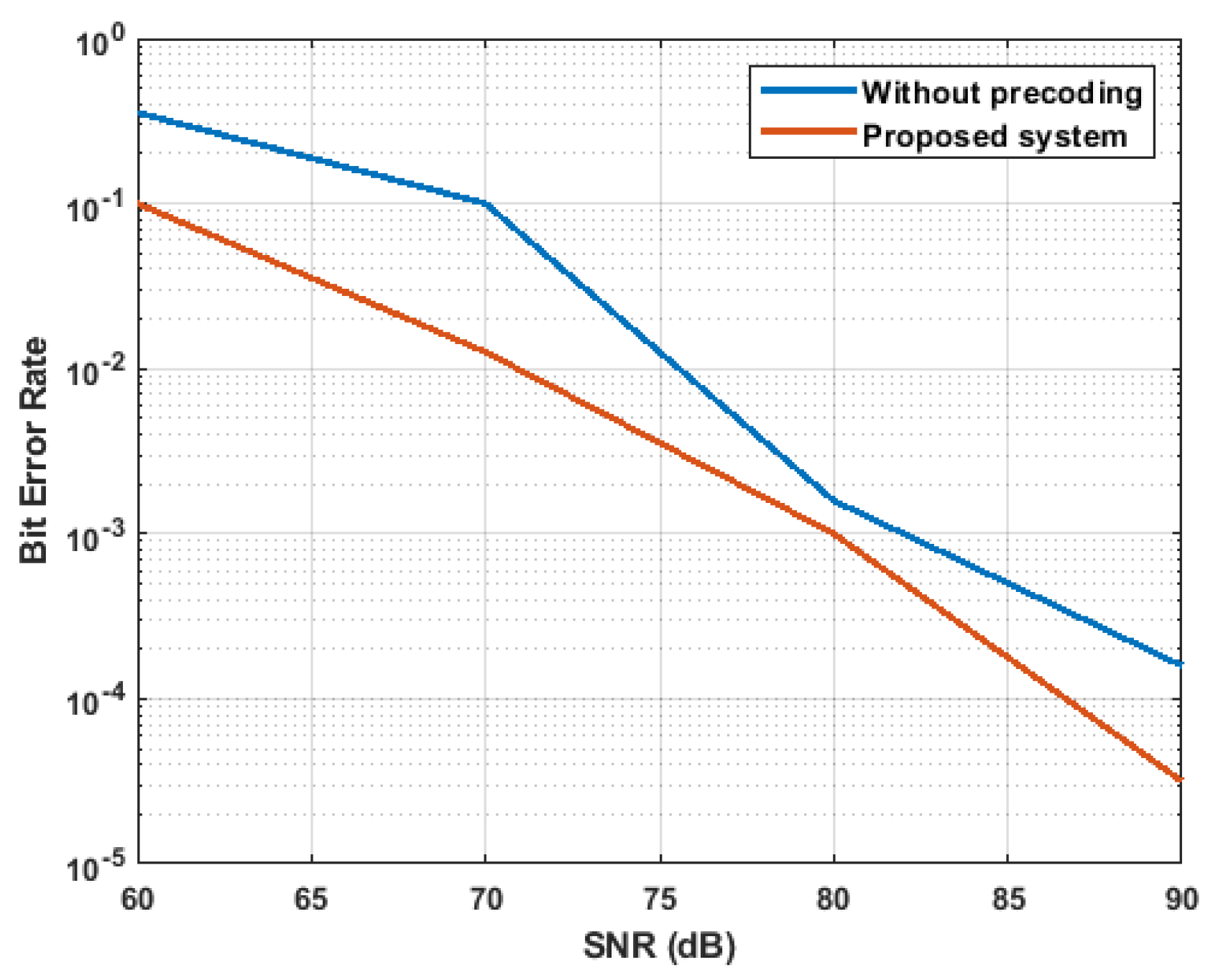
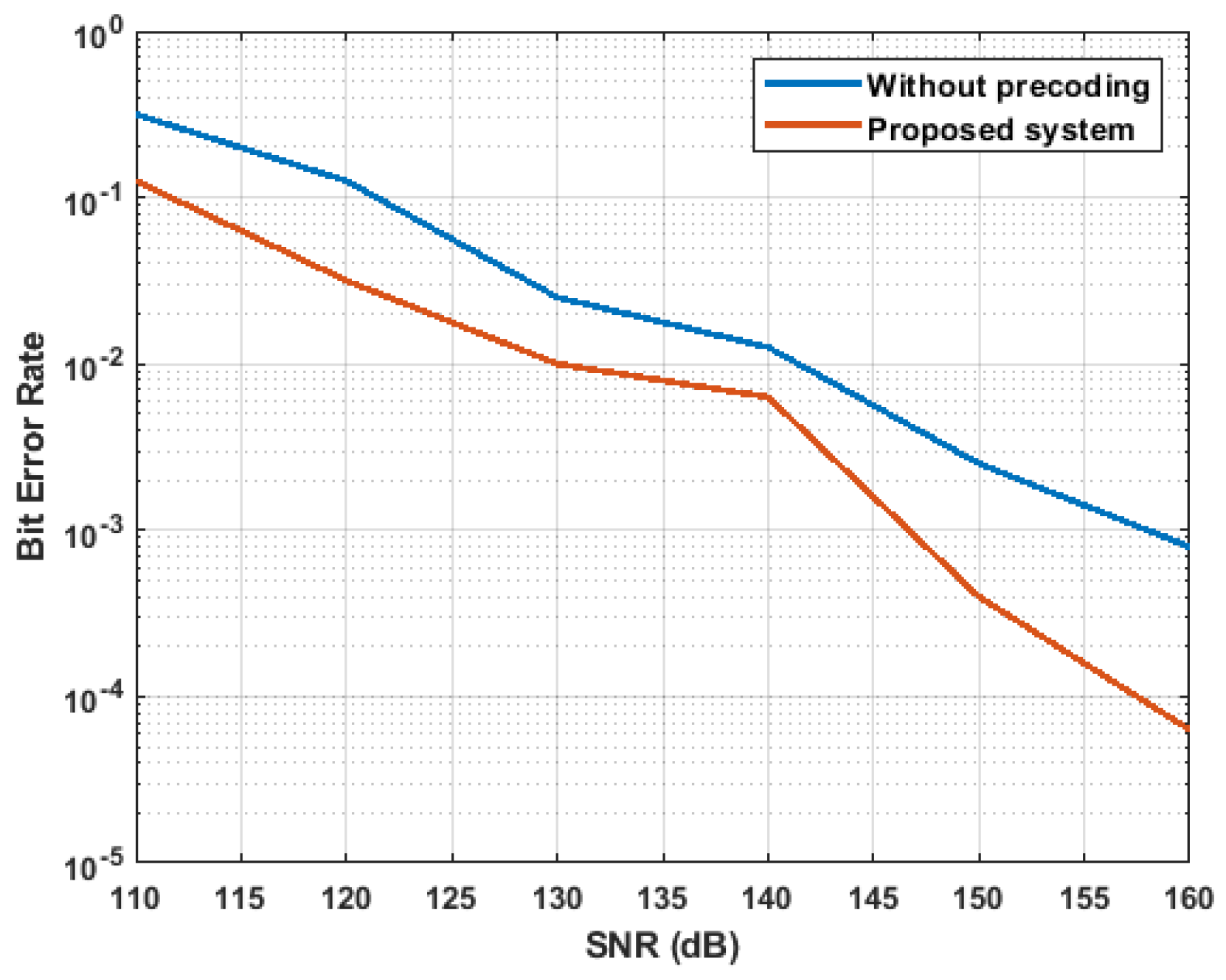
The performances of the proposed methodology had errors occur during the data transmission (i.e., BER) and throughput. The aforesaid performance measures are explained as follows:
  • Bit Error Rate
    The amount of errors at a specified unit time is called the BER. Generally, the BER is the ratio rate between the amount of error bits to the total transmitted bits over the MIMO-VLC channel and the Equation (17) expresses the BER.
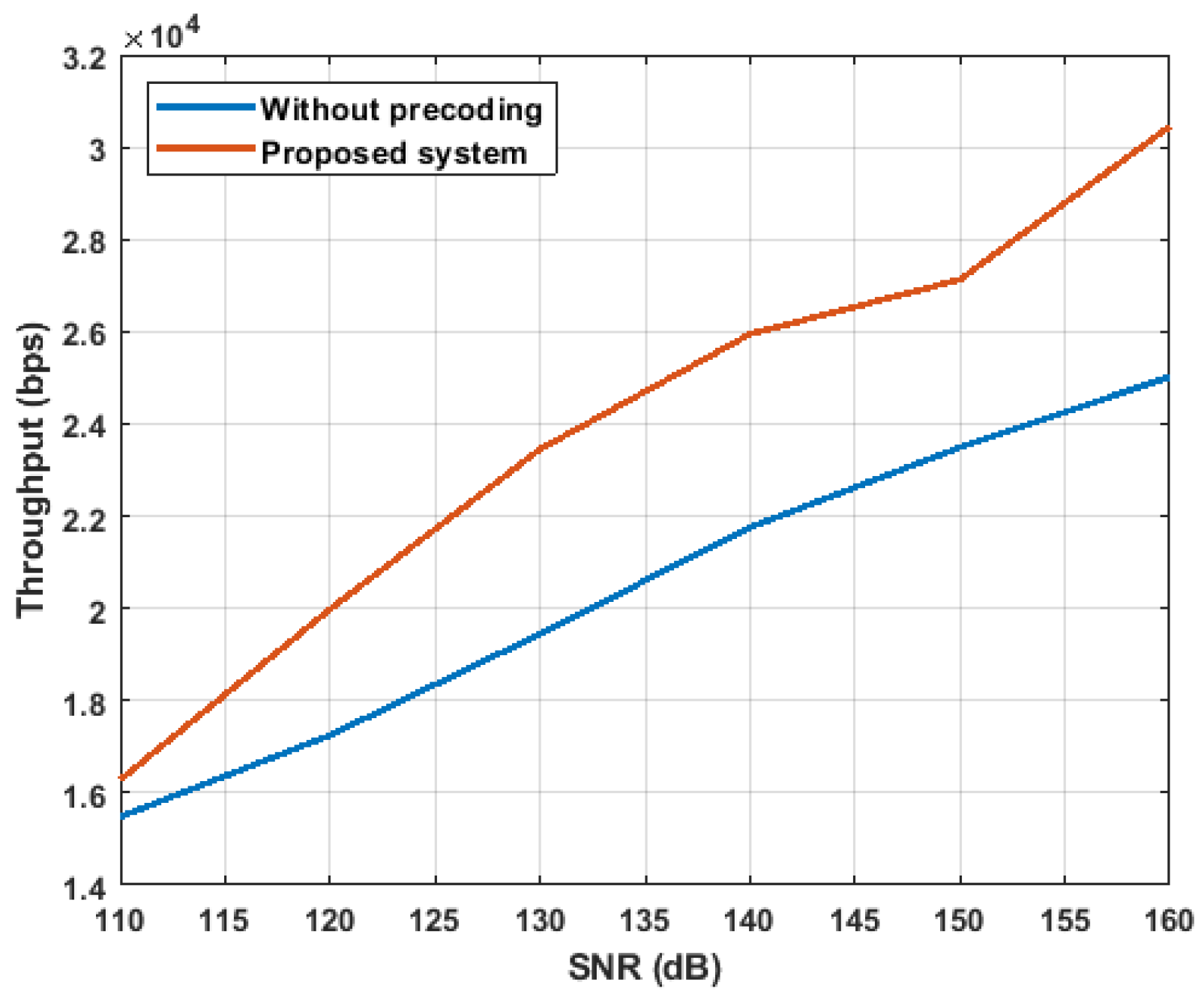
    B E R = E r r o r   b i t s T o t a l   t r a n s m i t t e d   b i t s
  • Throughput
    Throughput is defined as number of bits transmitted from one place to another place. Generally, throughput is measured as bits per second.

4.2. Performance Analysis

The performance of the proposed system is evaluated with BBD precoding without precoding technique. The indoor MIMO-VLC system performances are analyzed in terms of BER with respect to the different SNR. In the case of indoor MIMO-VLC system without precoding, the data transmission from the LED transmitter to PD receiver is analyzed to evaluate the proposed system. The performance of the proposed system is analyzed for three different scenarios.
Table 3 shows the scenarios considered to analyze the indoor MIMO-VLC system that shows the length, width and height of the room. The performance analysis for the aforesaid three different scenarios are given as follows:
Figure 2, Figure 3 and Figure 4 shows the BER, throughput and power for scenario 1 of the indoor MIMO-VLC system. From Figure 2 and Figure 3, it can be concluded that the proposed system has less BER and higher throughput due to the utilization of BBD precoding in the data transmission. Additionally, the power consumption of the proposed system during the data transmission is less, when compared to the MIMO-VLC system without precoding technique. For example, the throughput for scenario 1 is 19,242 bps at 70 dB; it is high when compared to the MIMO-VLC system without precoding. The BBD precoding used in the proposed system minimizes errors due to the thermal noise, shot noise and phase noise.
The BER, throughput and power analysis of proposed system with MIMO-VLC system without precoding is illustrated in Figure 5, Figure 6 and Figure 7, respectively. From Figure 5 and Figure 6, it can be concluded that the proposed method achieves higher throughput and lesser BER during the data transmission. In addition, the power consumed by the proposed system is less than the proposed system without precoding technique. For example, the proposed system BER of scenario 2 is 0.0100 at 20 dB; it is less when compared to the MIMO-VLC system without precoding. Moreover, the proposed system’s power consumption is 1.4   μ W at 60 dB; it is less when compared to the MIMO-VLC system without precoding.
Figure 8, Figure 9 and Figure 10 show the BER, throughput and power of scenario 3 for the indoor MIMO-VLC system. From Figure 8 and Figure 9, it can be concluded that the proposed system has less BER and high throughput due to the utilization of BBD precoding in the data transmission. In addition, Figure 10 shows that the proposed system achieves lesser power consumption than the MIMO-VLC system without precoding technique. For example, the BER for scenario 3 is 6.3 × 10⁻⁵ at 70 dB; it is less when compared to the MIMO-VLC system without precoding. Additionally, the throughput of the proposed system is 26 Kbps at 140 dB; it is high when compared to the MIMO-VLC without any precoding. Due to less BER, the data rate achieved in the receiver is high in the proposed system. The higher data rate achieved in the receiver increases the throughput obtained in the BBD-based MIMO-VLC system. Besides, the power consumption of the proposed system at 150 dB is 2.63   μ W ; it is less when compared to the MIMO-VLC without precoding. The utilized BBD precoding removes the user interferences and reduces errors due to thermal noise, shot noise and phase noise.

4.3. Comparative Analysis

The proposed system efficiency is known by comparing the proposed system with existing methods. The existing methods used for the comparison are OAP [22], FBM [23] and NRZ-OOK-LOS [24]. The OAP scheme is developed for the downlink communication of MIMO VLC. The information about the transmitted symbols are used in the OAP for correlating the interference in the MIMO-VLC system [22]. The frequency translated version of the SRRC filter develops the quadrature orthogonal filter-banks and multiple in phase. These are used to modulate information symbols for creating the transmit signal in the FBM-based signal design scheme [23]. The BER for LOS, LOS with 1st reflection, LOS with 1st and 2nd reflection are analyzed in the 4 × 4 MIMO-VLC system [24].
Similar to the performance analysis, the comparative analysis of the proposed method is evaluated for the same three scenarios. The proposed system with the comparison of OAP [22], FBM [23] and NRZ-OOK-LOS [24] are carried out for scenario 1, 2 and 3, respectively. The comparative analysis of the scenario 1, 2 and 3 are depicted in Table 4, Table 5 and Table 6, respectively. From the Tables, it can be concluded that the proposed method achieves less BER when compared to the OAP [22], FBM [23] and NRZ-OOK-LOS [24] techniques. For example, the proposed system BER value of scenario 3 is 0.0003 at 150 dB; it is less when compared to the NRZ-OOK-LOS [24] technique. The reason behind the proposed system with less BER is the reduction of errors occurred during the communication by using the BBD precoding.

5. Conclusions

In this paper, the communication performances of the 4 × 4 indoor MIMO-VLC system are analyzed under different noise constraints. The precoding matrix from the BBD is utilized in the MIMO-VLC transmitter to modify the input data stream before transmission. The interferences such as thermal noise, shot noise and phase noise are mitigated by using BBD-based precoding in communication. Besides, the QAM modulation/demodulation improves the transmission of the indoor MIMO-VLC system. From the performance analysis, it is known that the proposed system has better performance than the MIMO-VLC without any precoding. Additionally, the communication performances of BBD-based MIMO-VLC are compared with the existing MIMO-VLC system in terms of BER. The throughput of the proposed system for scenario 3 is 26 Kbps at 140 dB; it is high when compared to the MIMO-VLC without any precoding. Moreover, the BER of the proposed system of scenario 1 is 0.0126 at 70 dB; it is less when compared to the OAP. Furthermore, the power allocation with an efficient beam-forming technique can be developed to improve the MIMO-VLC system performances.

Author Contributions

Methodology, formal analysis and investigation, P.S.; software, resources and data curation, G.B.R.; data collection and validation, J.S.; original draft preparation—review and editing, P.B.D.; supervision and project administration, R.P.d.P. All authors have read and agreed to the published version of the manuscript.

Funding

This research received no external funding.

Conflicts of Interest

The authors declare no conflict of interest.

References

  1. Wang, Q.; Wang, Z.; Dai, L. Multiuser MIMO-OFDM for visible light communications. IEEE Photonics J. 2015, 7, 1–11. [Google Scholar] [CrossRef]
  2. Jain, S.; Mitra, R.; Bhatia, V. Adaptive precoding-based detection algorithm for massive MIMO visible light communication. IEEE Commun. Lett. 2018, 22, 1842–1845. [Google Scholar] [CrossRef]
  3. Sifaou, H.; Kammoun, A.; Park, K.H.; Alouini, M.S. Robust transceivers design for multi-stream multi-user MIMO visible light communication. IEEE Access 2017, 5, 26387–26399. [Google Scholar] [CrossRef] [Green Version]
  4. Feng, R.; Dai, M.; Wang, H.; Chen, B.; Lin, X. Linear precoding for multiuser visible-light communication with field-of-view diversity. IEEE Photonics J. 2016, 8, 1–8. [Google Scholar] [CrossRef]
  5. Kumar, C.R.; Jeyachitra, R.K. Power efficient generalized spatial modulation MIMO for indoor visible light communications. IEEE Photonics Technol. Lett. 2017, 29, 921–924. [Google Scholar] [CrossRef]
  6. Abdulkafi, A.A.; Hardan, S.M.; Bayat, O.; Ucan, O.N. Multilayered optical OFDM for high spectral efficiency in visible light communication system. Photonic Netw. Commun. 2019, 38, 299–313. [Google Scholar] [CrossRef]
  7. Dai, M.; Yuan, J.; Feng, R.; Wang, H.; Chen, B.; Lin, X. A power allocation method for 2 × 2 VLC-MIMO indoor communication. Opt. Rev. 2016, 23, 678–682. [Google Scholar] [CrossRef]
  8. Chen, C.; Zhong, W.D.; Wu, D. On the coverage of multiple-input multiple-output visible light communications. IEEE/OSA J. Opt. Commun. Netw. 2017, 9, D31–D41. [Google Scholar] [CrossRef]
  9. Esmail, M.A.; Fathallah, H.A. Indoor visible light communication without line of sight: Investigation and performance analysis. Photonic Netw. Commun. 2015, 30, 159–166. [Google Scholar] [CrossRef]
  10. Werfli, K.; Chvojka, P.; Ghassemlooy, Z.; Hassan, N.B.; Zvanovec, S.; Burton, A.; Haigh, P.A.; Bhatnagar, M.R. Experimental demonstration of high-speed 4 × 4 imaging multi-CAP MIMO visible light communications. J. Light. Technol. 2018, 36, 1944–1951. [Google Scholar] [CrossRef] [Green Version]
  11. Chen, C.; Zhong, W.D.; Yang, H.; Du, P. On the performance of MIMO-NOMA-based visible light communication systems. IEEE Photonics Technol. Lett. 2017, 30, 307–310. [Google Scholar] [CrossRef]
  12. Yang, H.; Chen, C.; Zhong, W.D.; Alphones, A. Joint precoder and equalizer design for multi-user multi-cell MIMO VLC systems. IEEE Trans. Veh. Technol. 2018, 67, 11354–11364. [Google Scholar] [CrossRef]
  13. Ali, T.; Balani, W. A robust pre-coding and hybrid equalization assisted MIMO-MU visible light communication system for QoS centric indoor communication. Telecommun. Syst. 2019, 72, 457–470. [Google Scholar] [CrossRef]
  14. Zhu, Y.J.; Liang, W.F.; Zhang, J.K.; Zhang, Y.Y. Space-collaborative constellation designs for MIMO indoor visible light communications. IEEE Photonics Technol. Lett. 2015, 27, 1667–1670. [Google Scholar]
  15. Sun, Z.G.; Yu, H.Y.; Tian, Z.J.; Zhu, Y.J. Linear precoding for MU-MISO VLC systems with noisy channel state information. IEEE Commun. Lett. 2018, 22, 732–735. [Google Scholar] [CrossRef]
  16. Hsu, C.W.; Chow, C.W.; Lu, I.C.; Liu, Y.L.; Yeh, C.H.; Liu, Y. High speed imaging 3 × 3 MIMO phosphor white-light LED based visible light communication system. IEEE Photonics J. 2016, 8, 1–6. [Google Scholar] [CrossRef]
  17. Wang, R.; Gao, Q.; You, J.; Liu, E.; Wang, P.; Xu, Z.; Hua, Y. Linear transceiver designs for MIMO indoor visible light communications under lighting constraints. IEEE Trans. Commun. 2017, 65, 2494–2508. [Google Scholar] [CrossRef]
  18. Park, K.H.; Oubei, H.M.; Alheadary, W.G.; Ooi, B.S.; Alouini, M.S. A Novel Mirror-Aided Non-Imaging Receiver for Indoor 2 × 2 MIMO-Visible Light Communication Systems. IEEE Trans. Wirel. Commun. 2017, 16, 5630–5643. [Google Scholar] [CrossRef] [Green Version]
  19. Kim, B.W.; Jung, S.Y. Channel capacity of the distributed MIMO relay in visible light communication systems. Photonic Netw. Commun. 2017, 34, 298–305. [Google Scholar] [CrossRef]
  20. Akande, K.O.; Popoola, W.O. MIMO techniques for carrierless amplitude and phase modulation in visible light communication. IEEE Commun. Lett. 2018, 22, 974–977. [Google Scholar] [CrossRef]
  21. Hong, Y.; Wu, T.; Chen, L.K. On the performance of adaptive MIMO-OFDM indoor visible light communications. IEEE Photonics Technol. Lett. 2016, 28, 907–910. [Google Scholar] [CrossRef]
  22. Marshoud, H.; Sofotasios, P.C.; Muhaidat, S.; Sharif, B.S.; Karagiannidis, G.K. Optical adaptive precoding for visible light communications. IEEE Access 2018, 6, 22121–22130. [Google Scholar] [CrossRef]
  23. Sathar, A.A.; Muneer, P.; Ijyas, V.T.; Usman, M.; Shamim, M.Z.M.; Shiblee, M. Filter-Bank Modulation Based Signal Design and Transmission Techniques for Intensity Modulated MIMO Visible Light Communication Systems. Wirel. Pers. Commun. 2019, 111, 1129–1150. [Google Scholar] [CrossRef]
  24. Kumar, A.; Ghorai, S.K. Effect of multipath reflection on BER performance of indoor MIMO-VLC system. Opt. Quantum Electron. 2018, 50, 388. [Google Scholar] [CrossRef]
Figure 1. Proposed Indoor MIMO-VLC system. (a) Transmitter. (b) Receiver.
Energies 13 03466 g001aEnergies 13 03466 g001b
Figure 2. Evaluation of Bit Error Rate (BER) for scenario 1.
Energies 13 03466 g002
Figure 3. Evaluation of throughput for scenario 1.
Energies 13 03466 g003
Figure 4. Evaluation of power for scenario 1.
Energies 13 03466 g004
Figure 5. Evaluation of BER for scenario 2.
Energies 13 03466 g005
Figure 6. Evaluation of throughput for scenario 2.
Energies 13 03466 g006
Figure 7. Evaluation of power for scenario 2.
Energies 13 03466 g007
Figure 8. Evaluation of BER for scenario 3.
Energies 13 03466 g008
Figure 9. Evaluation of throughput for scenario 3.
Energies 13 03466 g009
Figure 10. Evaluation of power for scenario 3.
Energies 13 03466 g010
Table 1. Parameters used in the indoor MIMO-VLC system.
ParameterDescription
M t Number of transmitting LEDs
M r Number of receiving LEDs
y Input signal vector
z Received signal vector
D C DC bias matrix
m Noise vector
H Square matrix
h j k d Desired channel paths
h j k i Interference channel paths
γ Responsivity
P Transmitting power of LED
m j Receiver noise
σ t h j 2 Thermal noise
σ s h j 2 Shot noise
q Electronic charge
B Bandwidth
I b Background current
I 2 bandwidth factor of noise
k Boltzmann’s constant
T Absolute temperature
G Gain of open-loop voltage
A j Area of PD
η PD’s fixed capacitance
Γ Channel noise factor of field effect transistor
g Transconductance of the FET
I 3 Weighting function
S I N R j Signal to interference plus noise ratio (SINR) in j th PD
d j k Distance among the transmitting LED and PD receiver
φ j k Emergence angle
ϕ j k Incidence angle
ϕ c PD’s field of view
t s ( ϕ j k ) Optical filter’s gain
g a ( ϕ j k ) Optical concentrator’s gain
r 0 ( φ j k ) Transmitting LED’s Lambertian radiant intensity
φ 1 / 2 Transmitter semiangle at half power
H b b d j SVD of BBD’s Square matrix
U b b d ( j ) Left singular vector matrix
V b b d ( j ) Right singular vector matrix
O Zero matrix
B b b d Precoding matrix
Table 2. Simulation parameters.
Parameters of LED Transmitter
Amount of LEDs per luminary60   ×   60
LED transmitter power10 mW
Semi angle of transmitter15°
Parameters of PD Receiver
FOV of receiver15°
PD area1.0 cm2
PD responsivity1 A/W
PD lens’ refractive index1.5
Gain of optical filter 1.0
Background current 100   μ A
Bandwidth factor of noise 0.562
Table 3. Scenarios for the analysis of indoor MIMO-VLC system.
Scenario 1
Length (X)5 m
Width (Y)5 m
Height (Z)3.5 m
SNR range10–60 dB
Scenario 2
Length (X)4 m
Width (Y)4 m
Height (Z)3 m
SNR range60–120 dB
Scenario 3
Length (X)5 m
Width (Y)5 m
Height (Z)3 m
SNR range160–260 dB
Table 4. Comparative analysis for scenario 1.
SNR (dB)BER Analysis
OAP [22]Proposed System
600.35480.1000
700.10000.0126
800.00160.0010
900.00013.16 × 10−5
Table 5. Comparative analysis for scenario 2.
SNR (dB)BER Analysis
FBM [23]Proposed System
100.15850.0501
200.03980.0100
300.01000.0025
400.00500.0006
500.00130.0001
600.00053.1 × 10−5
Table 6. Comparative analysis for scenario 3.
SNR (dB)BER Analysis
NRZ-OOK-LOS [24]Proposed System
1100.31620.1259
1230.12590.0316
1300.02510.0100
1400.01260.0063
1500.00250.0003
1600.00076.3 × 10−5

